instruction manual - hanse environmental inchanseenv.com/phocadownload/7sf-barber-colman.22.pdf5...
TRANSCRIPT

Instruction Manual
1262-IN-005-0-03February 1998
DG
Model 7SF
2
1/16 DIN, FOUR DIGIT DISPLAYCONTROLLER
MODEL: 0 7 S F - 9 3 1 - 3 0- 0 - 0 0Field. 1 2 3 4 5 6 7 8 9 10 11 12 13 14 15
Fields 1 through 4. BASE07SF - Controller
Field 5. INPUT9 - TC types J, K, L, N, R and S; Pt 100, 3 wire RTD;
0 to 20 mAdc and 4 to 20 mAdc;0 to 60 mVdc and 12 to 60 mVdc;0 to 5 Vdc or 1 to 5 Vdc;0 to 10 Vdc or 2 to 10 VdcNOTE: All inputs are factory calibrated and
selectable by keys. Factory set at type J.
Field 6. CONTROL ACTION3 - PID and autotuning (Smart AT)
Field 7. OUTPUT 11 - Relay6 - SSR
Field 8. OUTPUT 21 - Relay (cooling/alarm)
Field 9. OPTIONS0 - None1 - Alarm 22 - Alarm 2, plus Hbd (heater breakdown)
(or logic input)3 - Alarm 2, plus RS-4854 - Alarm 2, plus RS-485 and Hbd (or logic input)
NOTE: For Hbd, order transformer separately.
Field 10. POWER SUPPLY3 - 100 to 240 Vac
Field 11. Mounting0 - Panel MountR - Wall or Rail Mount
Fields 12 through 15. RESERVED

3
CONGRATULATIONS
Congratulations on your purchase of one of the easiest toconfigure controllers on the market. After a four stepconfiguration procedure, your process will be up and running.
GUIDE TO SIMPLE SET-UP
Only four steps are required to set-up your controller:1. Wire the instrument2. Configure the instrument3. Check the operating mode parameters4. Check the autotune (Smart AT) process
Unpack theInstrument
Wiring
Configuration
OperatingParameters
Autotuning
SV

4
CAUTION: USE WIRE SUITABLEFOR 75 °C MINIMUM
IMPORTANT!
Terminal identification of the panel mount controller isdifferent from terminal identification of the wall/rail mountcontroller! This manual contains wiring instructions forboth types of controllers.
Be sure to follow the instructions that pertain to thecontroller you are installing!
Contents
Mounting RequirementsPanel Mount Controller ................................. 5Wall or Rail Mount Controller ........................ 6
DimensionsPanel Mount Controller ................................. 7Wall or Rail Mount Controller ........................ 8
Wiring GuidelinesPanel Mount Controller ................................. 9Wall or Rail Mount Controller ...................... 16
Configuration ................................................. 22Preliminary Hardware Settings ................... 22Configuration Key Functions ...................... 23Configuration Procedure ............................. 23Advanced Configuration Procedure ........... 26
Operating Mode............................................. 28Indicators .................................................... 29Operating Key Functions ............................ 29Enable/Disable the Control Output ............. 29SP/SP2 Selection ........................................ 30Manual Function ......................................... 30Digital Communications .............................. 30Autotuning (Smart AT) Function .................. 31Operating Parameters ................................. 31Error messages ........................................... 34Default Parameters ..................................... 34Default Configuration Parameters .............. 35
Specifications ................................................ 37Calibration ..................................................... 41
Calibration Parameters ............................... 41Procedure .................................................... 42Entering Calibration Values ......................... 42
Maintenance .................................................. 47

5
MOUNTING REQUIREMENTSPANEL MOUNT CONTROLLER
Select a mounting location with the followingcharacteristics:1) Low vibration.2) An ambient temperature range between 0 and 50 °C
(32 and 122 °F).3) Easy access to the rear of the instrument.4) No corrosive gases (sulfuric gas, ammonia, etc.).5) No water or other fluid (i.e., condensation).6) A relative humidity of 20 to 80% non-condensing.
Bracket
Panel
Gasket
The instrument can be mounted on a panel up to 15 mm(0.591 in) thick with a cutout of 45 x 45 mm (1.772 x 1.772in) - see outline in “Dimensions and Panel Cutout.”
Panel surface texture must be smoother than 6.3 µm.
To assure IP65 and NEMA 4X protection, insert the panelgasket between the instrument and the panel as shownbelow.
Install the instrument as follows:1) Insert the instrument case in the gasket.2) Insert the instrument in the panel cutout.3) Pushing the instrument against the panel, insert the
mounting bracket.4) Torque the mounting bracket screws between 0.3 and
0.4 Nm (0.25 and 0.32 lb/in).5) Make sure the instrument will not move within the
cutout to insure NEMA 4X/IP65 protection.
6
MOUNTING REQUIREMENTSWALL OR RAIL MOUNTCONTROLLER
WARNING:1) The correct functionality of these instruments is
guaranteed only if transport, storage, installation,wiring, working condition and maintenance areexecuted in compliance with this manual.
2) The protection degree of these instruments is equalto IP 20 (according to IEC529) and they are connectedto dangerous power lines, for these reasons:
- installation, wiring and maintenance must beexecuted by qualified personnel;
- all warnings contained in this manual must becomplied.
3) The safety requirements for Permanently ConnectedEquipment say:
- a switch or circuit-breaker shall be included in thebuilding installation;
- It shall be in close proximity to the equipment andeasy to reach for the operator;
- it shall be marked as the disconnecting device forthe equipment.
NOTE: a single switch or circuit-breaker can drive morethan one instrument.
4) Before to execute any operation on the connections,disconnect the instrument from the power line bythe circuit breaker.
GENERAL ASSEMBLING INFORMATIONSelect a cleaned location, easy to reach, where minimumvibrations are present and the ambient temperature iswithin 0 and 50 °C (32 and 122 °F).These instruments can be mounted either on wall or ona DIN rail.
RAIL MOUNTINGUse DIN rail in accordance with EN 50 022 (35 x 7.5 mmor 35 x 15 mm)
WALL MOUNTINGFor wall mounting, use the (A) holes.In this case it is advisable to use four M4 screws with atorque of 1Nm.
7SF
(A)
(A)

7
DIMENSIONSPANEL MOUNT CONTROLLER
45 mm, -0, +0.6 mm(1.772 in, -0, +0.024 in)
45 mm, -0, +0.6 mm(1.772 in, -0, +0.024 in)
75 mm(2.953 in)
10 mm(0.394 in)
60 mm(2.362 in)
122 mm(4.803 in)
48 mm(1.890 in)
48 mm(1.890 in)
8
DIMENSIONSWALL OR RAIL MOUNT CONTROLLER
MAN SV2AT
7SF
RMT
144 (5.67 in.)57.5 (2.26 in.)
106(4.17 in.)
43 (1.69 in.)
4.5(0.18 in.)
46 (
1.8
1 in
.)
5 (
0.2
0 in
.)
48(1.89 in.)
96(3.78 in.)
5 (0.20 in.)

9
WIRING GUIDELINESPANEL MOUNT CONTROLLERTERMINAL BOARD
1
3
4
5
6
7
8
9
10
2
11
13
14
15
12
RS
485
NOOUT3
SSROUT1
COUT2/3
LIN
EA
R
NO
C
PW
R L
INE
100/
240V
ac
A/A'
B/B'
NOOUT2
INC
T/S
P-S
P2
C
+
_
TC
RT
D
+
_
NOTE: When a relay output is used to drive an inductiveload, connect an external snubber network (RC)across the terminals:
CR
in accordance with the following table:
daoLtnerruC
C)Fµ(
R(Ω)
P)W(
dnarotsiseRegatloVroticapaC
Am04< 740.0 001 2/1 caV062
Am051< 1.0 22 2 062 caV
pmA5.0< 33.0 74 2 062 caV
A) MEASURING INPUTS (PANEL MOUNT)Any external components (like zener diodes, etc.)connected between the sensor and input terminals maycause measurement errors (excessive or unbalanced lineresistance or possible leakage currents).
TC INPUT
Shield
Shield
10
9
10
9
+
-
+
-
SAFETY NOTE:1) Do not run input wires with power cables.
NOTES:1) For TC wiring use proper compensating cable,
preferably shielded.2) Shielded cable should be grounded at one end only.

10
RTD INPUT (PANEL MOUNT)
8 9
RTD
10 8 9
RTD
10
SAFETY NOTE:1) Do not run RTD wires with power cables.
NOTES:1) Ground shielded cable at one end only.2) Use the correct size copper wires.3) The resistance of the 3 wires must be the same.
Any external components (like zener diodes, etc.)connected between the sensor and input terminals maycause measurement errors (excessive or unbalanced lineresistance or possible leakage currents).
LINEAR INPUT (PANEL MOUNT)
10
9
mA,mVorV
Shield
-
+
10
9
mA,mVorV
Shield
-
G
+
SAFETY NOTE:1) Do not run input wires with power cables.
NOTES:1) High line resistance can cause measurement errors.2) When shielded cable is used, ground it at one end
only to avoid ground loop currents.3) The input impedance is equal to:
Less than 5 ohms for 2 mA inputGreater than 1 megohms for 60 mVdc inputGreater than 200 k ohms for 5 Vdc input.Greater than 400 k ohms for 10 Vdc input.

11
THERMOCOUPLE COMPENSATING CABLE COLOR CODES.
elpuocomrehTlairetaM
hsitirB3481SB
naciremA1.69CMISNA
namreG01734NID
hcnerF100-81EFN
TreppoC
natnatsnoC+-
etihWeulBeulB
+-
eulBdeReulB
+-
deRnworBnworB
+-
wolleYeulBeulB
L/JnorI
natnatsnoC+-
wolleYeulBkcalB
+-
etihWdeR
kcalB
+-
deReulBeulB
+-
wolleYkcalBkcalB
KmuimorhClekciNmunimulAlekciN
+-
nworBeulBdeR
+-
wolleYdeR
wolleY
+-
deRneerGneerG
+-
wolleYelpruPwolleY
RmunitalP/munitalP
muidohR%31+-
etihWeulB
neerG
+-
kcalBdeR
neerG
+-
deRetihWetihW
+-
etihWneerGneerG
SmunitalP/munitalP
muidohR%01+-
etihWeulB
neerG
+-
kcalBdeR
neerG
+-
deRetihWetihW
+-
etihWneerGneerG
ElemorhC
natnatsnoC+-
nworBeulB
nworB
+-
teloiVdeR
teloiV
---
---
BhR%03munitalP
hR%6munitalP---
+-
yerGdeRyerG
---
---
N lisiN/lisorciN - - - -
12
B) CURRENT TRANSFORMER INPUT (PANELMOUNT)SAFETY NOTE:Do not run current transformer input wiring with AC powercables.
NOTE:1) The minimum active period to perform this
measurement is 400 ms.2) This feature excludes the logic input function.3) Input impedance is equal to 10 ohms.
14
C ur ren t
H ea ter
tran sform er
15
This input allows to measure and display the currentrunning in the load driven by output 1 during the on andoff period of the out 1 cycle time. By this feature, out 1failure detection is also available.
C) LOGIC INPUT (PANEL MOUNT)This input selects between SP and SP2 as the operatingsetpoint.
SAFETY NOTES:1) Do not run logic input wiring with AC power cables.2) Use an external dry contact capable of switching 0.5
mA, 5 Vdc.
NOTES:1) The instrument needs 100 ms to recognize a contact
status variation.2) This feature excludes the current transfrormer input.3) The logic input is not isolated by the measuring input.
14
Logic input
15
D.1) RELAY OUTPUTS (PANEL MOUNT)
1
2
3
OUT 2(cooling/AL1)
OUT 3(AL2)
NO - OUT 2
C - OUT 2/3
NO - OUT 3
6
7
OUT 1(heating)
C
NO
All relay contacts are protected by varistor againstinductive load with inductive component up to 0.5 A.OUT 1: Contact rating of 3 Amps/250 Vac resistive load.OUT 2 and 3: Contact rating of 2 Amp/250 Vac resistiveload.Operations at specified rating: 1 x 10⁵

13
D.3) VOLTAGE OUTPUTS FOR SSR DRIVE(PANEL MOUNT)
6+
+
--
OUT 1
7
Solid State Relay
THIS IS A TIME PROPORTIONING OUTPUT.
Logic voltage for SSR drive.Logic level 0: Less than 0.5 Vdc.Logic status 1: 24 Vdc ±20% @ 1 mA.
14 Vdc ±20% @ 20 mA.Maximum current = 20 mA.
NOTE: This output is not isolated. A double orreinforced isolation between the instrumentoutput and the power supply is accomplishedby an external solid state relay.
SAFETY NOTES:1) To avoid electric shock, connect power line at the
end of the wiring procedure.2) Do not run input wires with power cables.
NOTES:1) For power connections use 16 AWG or larger wires
rated for at least 75 °C.2) Use copper conductors only.
D.2) INDUCTIVE LOADS (PANEL MOUNT)High voltage transients can occur when switchinginductive loads. It is recommended to install an additionalRC network across the internal contacts as shown.
The same problem can occur when a switch is used inseries with the internal contacts.
L O A D
CR
P O W ER L IN E
It is recommended to install an additional RC networkacross the external contacts as close to the instrumentterminals as possible.
The value of capacitor (C) and resistor (R) are shown inthe following table.
daoLtnerruC
C)Fµ(
R(Ω)
P)W(
dnarotsiseRegatloVroticapaC
Am04< 740.0 001 2/1 caV062
Am051< 1.0 22 2 062 caV
pmA5.0< 33.0 74 2 062 caV
pmA1< 74.0 74 2 062 caV
-
Relay output wiring must be as far away as possible frominput wiring and communication cables.

14
E) SERIAL INTERFACE (PANEL MOUNT)The RS-485 interface can connect up to 30 instrumentswith the remote master unit (see below).
11
COMMON
B/B' B'/B
A/A' A'/A
12
13
INSTRUMENT
MASTER
Maximum cable length: 1.5 km (9/10 mile) at 9600 BAUD.
NOTE: According to EIA specification for RS-485:a)The “A“ terminal of the generator shall be negative with
respect to the “B“ terminal for a binary 1 (MARK orOFF) state.
b) The “A“ terminal of the generator shall be positivewith respect to the “B“ terminal for a binary 0 (SPACEor ON) state.
11
COMMON
B/B' B'/B
A/A' A'/A
12
13
INSTRUMENT
11
12
13
INSTRUMENT
MASTER
Connect the instruments (maximum of 30) to the masterunit by interface communication type RS-485.

15
F) POWER LINE WIRING (PANEL MOUNT)
4
5
100 to 240 Vac rms 50/60 Hz or 24 Vac/Vdc
N
NR (S, T)
R (S, T)
SAFETY NOTES:1) Do not run input wires with power cables.2) Permanently connected equipment must include a
switch or circuit-breaker in the installation. Place it inclose proximity to the equipment and within easyreach of the operator. Mark it as the disconnectingdevice for the equipment. A single switch or circuit-breaker can drive more than one instrument.
3) To avoid shock and possible instrument damage,connect power last.
4) Before connecting the power line, check that thevoltage is correct (see Model Number).
5) Connect neutral line, if present, to terminal 4.
NOTES:1) For supply connections use 16 AWG or larger wires
rated for at least 75 °C.2) Use copper conductors only.4) The power supply input is not fuse protected. Please
provide fusing as shown:
ylppuSrewoP epyT tnerruC egatloV
cdV/caV42 T Am005 V052
caV042/001 T Am521 V052
When the fuse is damaged the instrument should bereturned to the supplier to check the power supply.
5) For 24 Vdc, the polarity is a do not care condition.

16
INPUT WIRING FORTC TYPE J, K, L, N AND T
MEASURING INPUTSNOTES:1) Any external components (like zener barriers etc.)
connected between sensor and input terminals maycause measurement errors due to excessive and/ornot balanced line resistance or possible leakagecurrents.
2) The input accuracy is equal to + 0.2 % f.s.v. (**) + 1dgt. @ 25°C of ambient temperature.
(**) For TC input, the f.s.v. should be referenced to thehigher f.s.v. of the TC selected.
WIRING GUIDELINESWALL OR RAIL MOUNTCONTROLLERConnections have to be executed when theinstrument is placed in its proper location.
MODEL 7SF RELAY TERMINAL BLOCK
14
+
_
Shield
14
+
_
Shield
15
15
TC INPUTTC type R and S (Wall & Rail Mount)
INPUT WIRING FOR TC TYPE R AND S
TC type J, K, L, N and T (Wall & Rail Mount)
11
+
_
Shield
11
+
_
Shield
15
15

17
16
RTD
1415 16
RTD
1415
NOTE:1) Do not run input wires with power cables.2) For TC wiring use proper compensating cable
preferable shielded.3) when a shielded cable is used, it should be connected
to one side only.
RTD INPUT (Wall & Rail Mount)
RTD INPUT WIRING
NOTE:1) Don’t run input wires together with power cables.2) Pay attention to the line resistance; an high line
resistance may cause measurement errors.3) When shielded cable is used, it should be grounded
at one side only to avoid ground loop currents.4) The resistance of the 3 wires must be the same.
LINEAR INPUT(Wall & Rail Mount)
mA, mV AND V INPUTS WIRING
NOTE:1) Do not run input wires together with power cables.2) Pay attention to the line resistance; a high line
resistance may cause measurement errors.3) When shielded cable is used, it should be grounded
at one side only to avoid ground loop currents.4) The input impedance is equal to:
< 5 ohms for 20 mA input> 1 M ohms for 60 mV input> 200 k ohms for 5 V input> 400 k ohms for 10 V input
Shield
_
+mA,mVorV14
+
_
G
mAmVorV
15
14
15

18
LOGIC INPUT (Wall & Rail Mount)
NOTES:1) Do not run logic input wiring together with power
cables.2) Use an external dry contact capable of switching
0.5 mA, 5 V dc.3) The instrument needs 100 ms to recognize a
contact status variation.4) The logic input is NOT isolated by the measuring
input.5) This feature excludes the current transformer
input.
LOGIC INPUT WIRING
This input (connections 12 and 13) is used either acurrent transformer input (relay only) or a logic input.When the logic input is selected, it is used to switch,by an external contact, from main set point to secondset point and viceversa.
logic input op. set pointopen SPclose SP2
CURRENT TRANSFORMER INPUT (For relay only)(Wall & Rail Mount)
Safety note:1) Do not run current transformer input wiring together
with AC power cables.2) This feature excludes the logic input function.3) The input impedance is equal to 10 Ω.
Fig. 10 - CURRENT TRANSFORMER INPUTWIRING
This input allows to measure and display the currentrunning in the load driven by the OUTPUT1 during theON and OFF period of the OUT 1 cycle time. By thisfeature it is also available the "OUT 1 failure detection"function.
12
13
Load
Currenttransformer
12
IN CT/SP-SP2 (for relay)SP-SP2 (for mA)
13

19
INDUCTIVE LOADS (Wall & Rail Mount)
High voltage transients may occur switching inductiveloads.Through the internal contacts these transients mayintroduce disturbances which can affect the instrumentperformances .For all outputs, the internal protection (varistor) assuresa correct protection up to 0.5 A of inductive component.
The same problems may occur when a switch is used inseries with the internal contacts as shown in Fig. 13.
Fig. 13 EXTERNAL SWITCH IN SERIES WITH THEINTERNAL CONTACT
In this case it is recommended to install an additionalRC network across the external contact as show in Fig.13. The value of capacitor (C) and resistor (R) are shownin the following table.
Anyway the cable involved in relay output wiring mustbe as far away as possible from input or communicationcables.
LOAD(mA)
<40 mA<150 mA<0.5 A
C(µF)
0.0470.1
0.33
R(Ω)
1002247
P.(W)
1/222
OPERATINGVOLTAGE
260 V AC260 V AC260 V AC
RELAY OUTPUTS (Wall & Rail Mount)
Fig. 12 RELAY OUTPUTS WIRING
The contact rating of OUT 1 is 3A/250V AC on resistiveload.The contact rating of OUT 2 and 3 is 2A/250V AC onresistive load.The number of operations is 1 x 10⁵ at specified rating.
NOTES1) To avoid electric shock, connect power line at the
end of the wiring procedure.2) For power connections use No 16 AWG or larger
wires rated for at last 75 °C.3) Use copper conductors only.4) Do not run input wires with power cables.
All relay contacts are protected by varistor againstinductive load with inductive component up to 0.5 A.
The following are recommendations avoid seriousproblems which may occur, when using relay output fordriving inductive loads.
OUT 1
OUT 2(AL1)
OUT 3(AL 2)
7
8
C
NO
1
2
3
NO - OUT 2
C - OUT 2/3
NO - OUT 3
LOAD
RC
POWERLINE

20
VOLTAGE OUTPUTS FOR SSR DRIVE (Wall & RailMount)
Fig. 14 SSR DRIVE OUTPUT WIRING
It is a time proportioning output.Logic level 0: Vout < 0.5 V DC.Logic level 1:- 14 V + 20 % @ 20 mA- 24 V + 20 % @ 1 mA.
Maximum current = 20 mA.
NOTE: This output is not isolated. A double orreinforced isolation between instrument output andpower supply must be assured by the external solidstate relay.
5
6COMMON
4
B'/BB/B'
A/A' A'/AMASTER
INSTRUMENT
+
_ _+
7
8
OUT 1
SOLID STATERELAY
SERIAL INTERFACE (Wall & Rail Mount)
RS-485 interface allows to connect up to 30 devices withone remote master unit.
Fig. 15 - RS-485 WIRING
The cable length must not exceed 1.5 km at 9600 BAUD.NOTE: The following report describes the signal senseof the voltage appearing across the interconnectioncable as defined by EIA for RS-485.
a) The ” A ” terminal of the generator shall be negativewith respect to the ” B ” terminal for a binary 1 (MARKor OFF) state.
b) The ” A ” terminal of the generator shall be positivewith respect to the ” B ” terminal for a binary 0(SPACE or ON)

21
8) The safety requirements for Permanently ConnectedEquipment say:
- a switch or circuit-breaker shall be includedin the building installation;
- It shall be in close proximity to theequipment and within easy reach of the operator;
- it shall be marked as the disconnecting device forthe equipment.
NOTE: a single switch or circuit-breaker can drive morethan one instrument.
9) When neutral line is present, connect it to terminal 9
10
R (S
,T)R (S,T)
N
9N
POWER LINE 100 V to 240 Vac(50/60 Hz)
or 24 Vac/Vdc
POWER LINE WIRING (Wall & Rail Mount)
Fig. 16 POWER LINE WIRING
NOTES:1) Before connecting the instrument to the power line,
make sure that line voltage corresponds to thedescription on the identification label.
2) To avoid electric shock, connect power line at theend of the wiring procedure.
3) For supply connections use No 16 AWG or largerwires rated for at last 75 °C.
4) Use copper conductors only.5) Do not run input wires with power cables.6) For 24 V DC the polarity is not a care condition.7) The power supply input is not fuse protected.
Please, provide it externally.
Power supply Type Current Voltage24 Vac/ Vdc T 500 mA 250 V100/240 Vac T 125 mA 250 V
When fuse is damaged, it is advisable to verify thepower supply circuit, so that it is necessary to send theinstrument back to your supplier.

22
CONFIGURATION
PRELIMINARY HARDWARE SETTINGS
1) Remove the instrument from its case.2) Set J106 according to the following table:
tupnIepyT
601J
2-1 4-3 6-5 8-7 01-9
DTR-CT nepo esolc nepo nepo nepo
Vm06 nepo esolc nepo nepo nepo
V5 esolc nepo esolc nepo nepo
V01 nepo nepo esolc nepo nepo
Am02 nepo nepo nepo esolc esolc
Note: place the jumper not used on pins 7-9.
J102V101
1 3 5 7 9
2 4 6 8 10
J106
Figure 1
3) Select the output 1 contact; NO (standard) or NC bysetting J102 according to the following table:
tcatnoC )dradnats(ON CN
201J 2-1 3-2
CAUTION: Solder carefully to avoid damage to PCB orother components.
OPEN INPUT CIRCUITThis instrument is able to identify an open circuit for TCand RTD inputs. The open input circuit condition for RTDinput is shown by an “overrange” indication. For TCinput, either an overrange indication (standard) orunderrange indication can be selected from the followingtable:
101HS 101HC noitacidnI
nepo esolc )tluafed(egnarrevo
esolc nepo egnarrednu
Both pads are located on the solder side of the CPU card.
SH101CH101
23
CONFIGURATION PROCEDURE
1) Switch off power to the instrument.2) Remove the instrument from its case.3) Open switch V101, located 1 inch behind the upper
right corner of the display (see Figure 1).4) Re-insert the instrument in its case.5) Switch on power to the instrument.
NOTE:If instrument displays “CAL”, press the s keyto select the configuration procedure “ConF”.
6) Press the FUNC key.
SER1 SERIAL INTERFACE PROTOCOLOff = No serial interface.Ero = Poll/select using proprietary protocol.nbUS = ModbusjbUS = Jbus
SER2 SERIAL LINK DEVICE ADDRESSNot available when “SEr1” = OFF.From 1 to 95 for proprietary protocol.From 1 to 255 for all other protocols.NOTE: The electrical characteristics of the RS-485
serial interface allows 31 devices maximum.
SER3 BAUD RATE FOR SERIAL LINKNot available when “SEr1” = OFF.From 600 to 19200 baud.NOTE: 19200 baud is displayed as 19.20.
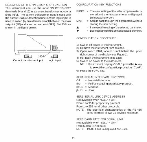
SELECTION OF THE IN CT/SPSP2 FUNCTIONThis instrument can use the input “IN CT/SP–SP2”(terminals 14 and 15) as a current transformer input or alogic input. The current transformer input is used withthe output 1 failure detection function; the logic input isused to switch (by an external contact) between the mainsetpoint (SP) and a second setpoint (SP2). Set J504 asshown in the figure below:
J504
Current transformer input Logic input
CONFIGURATION KEY FUNCTIONS
FUNC = The new setting of the selected parameter isstored and the next parameter is displayed(in increasing order).
MAN = Scrolls back through the parameters withoutstoring the new setting.
s = Increases the setting of the selected parameter.t = Decreases the setting of the selected parameter.

24
P2 DECIMAL POINT POSITIONThis parameter is available only when a linear input isselected (P1 = 11, 12,13,14,15,16, 17 or 18).
- - - - . = No decimal.- - - . - = One decimal place.- - . - - = Two decimal places.- . - - - = Three decimal places.
P3 INITIAL SCALE VALUE (LOW)Can be set with keys from -1999 to 4000 for linear inputs,and within the input range for TC and RTD. When thisparameter is modified, rL will also change.
P4 FULL SCALE VALUE (HIGH)Can be set with keys from -1999 to 4000 for linear inputs,and within the input range for TC and RTD. When thisparameter is modified, rH will also change.
The initial and full scale values determine the input spanused by the PID algorithm, autotuning (Smart AT), andthe alarm functions.
NOTE: Minimum input span in absolute value (S= P4 - P3) is as follows:
For linear inputs, S ≥100 units.For TC input with °C readout, S ≥ 300 °C.For TC input with °F readout, S ≥• 550 °F.For RTD input with °C readout, S •≥ 100 °C.For RTD input with °F readout, S ≥ 200 °F.
P5 OUTPUT 1 TYPErEL = Relay (cycle time, “CY1”, will be forced to 15
seconds).SSr = SSr (cycle time, “CY1”, will be forced to 4
seconds).
P6 OUTPUT 1 ACTIONThis parameter is skipped if P7 = 4.rEV = Reverse acting (Heating).dir = Direct acting (Cooling).
SER4 BYTE FORMAT FOR SERIAL LINKNot available when “SEr1” = OFF.7E = 7 bits + even parity (for proprietary protocol only).7O = 7 bits + odd parity (for proprietary protocol).8E = 8 bits + even parity.8O = 8 bits + odd parity.8 = 8 bits without parity.
P1 INPUT TYPE AND STANDARD RANGE0 = TC type L range 0 to +400.0 °C1 = TC type L range 0 to +900 °C2 = TC type J range -100.0 to +400.0 °C3 = TC type J range -100 to +1000 °C4 = TC type K range -100.0 to +400.0 °C5 = TC type K range -100 to +1370 °C6 = TC type N range -100 to +1400 °C7 = TC type R range 0 to +1760 °C8 = TC type S range 0 to +1760 °C9 = RTD type Pt 100 range -199.9 to +400.0 °C10 = RTD type Pt 100 range -200 to +800 °C11 = mV Linear range 0 to 60 mV12 = mV Linear range 12 to 60 mV13 = mA Linear range 0 to 20 mA14 = mA Linear range 4 to 20 mA15 = V Linear range 0 to 5 V16 = V Linear range 1 to 5 V17 = V Linear range 0 to 10 V18 = V Linear range 2 to 10 V19 = TC type L range 0 to +1650 °F20 = TC type J range -150 to +1830 °F21 = TC type K range -150 to +2500 °F22 = TC type N range -150 to +2550 °F23 = TC type R range 0 to +3200 °F24 = TC type S range 0 to +3200 °F25 = RTD type Pt 100 range -199.9 to +400.0 °F26 = RTD type Pt 100 range -330 to +1470.0 °F27 = TC type T range -199.9 to +400.0°C28 = TC type T range -330 to +750°CNOTE: Selecting P1 = 0, 2, 4, 9, 25 or 27 sets thedigital filter (P36) to “FLtr”, all remaining ranges it willset to “nOFL”. If a different selection is needed, P36can be modified.

25
P7 OUTPUT 2 FUNCTION0 = None1 = Used as Alarm 1 output and Alarm 1 is
programmed as a process alarm.2 = Used as Alarm 1 output and Alarm 1 is
programmed as a band alarm.3 = Used as Alarm 1 output and Alarm 1 is
programmed as a deviation alarm.4 = Used as second control output (Cooling output).NOTE: Setting P7 = 4 forces P6 = “rEV”.
P8 COOLING MEDIAAvailable only when P7 = 4.Alr = Air OlL = Oil H2O = WaterChanging P8 forces the cycle time and relative coolinggain to the default settings of the selected cooling media.When: P8 = Alr - CY2 = 10s and rC = 1.00
P8 = OlL - Cy2 = 4s and rC = 0.80P8 = H2O - CY2 = 2s and rC = 0.40
P9 ALARM 1 OPERATING MODEAvailable only when P7 = 1, 2 or 3.H.A. = High alarm (or outside the band) with auto. reset.L.A. = Low alarm (or inside the band) with auto. reset.H.L. = High alarm (or outside the band) with man. reset.L.L. = Low alarm (or inside the band) with man. reset.
P10 OPTIONAL FEATURESOFF = No option.SP2 = Digital input for SP/SP2 selection.n.O. = Current measurements made during the ON
period (load driven from a N.O. relay contactor a logic status 1 for an SSR).
n.C. = Current measurements made during the OFFperiod (load driven from a N.C. relay contactor a logic status 0 for an SSR).
P11 CURRENT TRANSFORMER RANGENot available when P10 = “OFF” or “SP2.” Can beprogrammed from 10 to 100 Amps.
P12 OUTPUT 3 FUNCTION0 = Not used for Alarm 2.1 = Used as Alarm 2 output and Alarm 2 is
programmed as a process alarm.2 = Used as Alarm 2 output and Alarm 2 is
programmed as a band alarm.3 = Used as Alarm 2 output and Alarm 2 is
programmed as a deviation alarm.NOTE: The output 3 relay operates as a logical OR
between Alarm 2 and the output 1 failuredetection (OFD) function.
P13 ALARM 2 OPERATING MODE AND OFDALARM RESET TYPE
Not available when P12 = 0 or P10 = “OFF” or SP2.H.A.= High alarm (outside band) with auto. reset.L.A. = Low alarm (inside band) with auto. reset.H.L. = High alarm (outside band) with man. reset.L.L. = Low alarm (inside band) with man. reset.NOTE: Use one of the low alarm types for OFD.
P14 PROGRAMMABILITY OF THE ALARM 2SETPOINT AND HYSTERESIS VALUES
Not available when P12 = 0.OPrt = Alarm 2 setpoint and hysteresis can be set
with keys in the operating mode.COnF = Alarm 2 setpoint and hysteresis can be set with
keys in the configuration mode.
P15 ALARM 2 SETPOINTNot available when P12 = 0 and P14 = “OPrt”.Range: For process alarm: Within the range limits.
For band alarm: From 0 to 500 units.For deviation Alarm: From -500 to 500 units.
P16 ALARM 2 HYSTERESIS VALUENot available when P12 = 0 and P14 = “OPrt”.Range: From 0.1 to 10.0% of the range selected with
P3 and P4 parameters, or 1 LSD.

26
P17 SOFT START SETPOINTThe “soft start” function allows the maximum outputpower to be limited (see the OLH operating parameter)for a programmable time period (see the tOL operatingparameter) at instrument start-up when the measuredvalue is lower than the setpoint. Enter the setpoint inengineering units.NOTE: This setpoint setting will not be used when
tOL = InF.
P18 SAFETY LOCK0 = Unlocked. All the parameters can be modified.1 = Locked. No parameter, except setpoints and
alarm manual reset, can be modified. For SmartAT, see P27.
2 to 4999 = Code, used in run time (see nnn parameter),to lock/unlock the device. For SP, SP2, andmanual reset of alarm, the lock/unlock conditionhas no affect. For Smart AT status, see P27.
5000 to 9999 = Code, used in run time (see nnnparameter), to lock/unlock the device. For SP,SP2, manual reset of alarm, AL1, AL2, Hbd, andSCA, the lock/unlock has no affect. For SmartAT, see P27.
Note: when safety lock is selected the code cannot bedisplayed. The display will show 0, 1, SFt.A if P18 is 2 to4999; or SFt.b if P18 is 5000 to 9999.
The configuration procedure is now complete. Theinstrument should show “–.–.–.–.” on both displays.Press the FUNC key; the instrument will return to thebeginning of the configuration procedure. To continuewith controller set-up go to the operating mode found inthe next section. To access the advanced configurationparameters proceed as follows:
1) Use the s and t keys to enter 234 on the display.2) Press the FUNC key.
ADVANCED CONFIGURATION PROCEDURE
P19 ALARM 1 ACTIONNot available when P7 = 0 or 4.rEV = Reverse (relay de-energized in alarm condition).dir = Direct (relay energized in the alarm condition).
P20 ALARM 1 STANDBYNot available when P7 = 0 or 4.OFF = Standby disabled.ON = Standby enabled.NOTE: If the alarm is a band or deviation alarm, the alarmis masked after a setpoint change or at start-up until theprocess variable reaches the alarm setpoint plus or minushysteresis. If the alarm is a process alarm, the conditionis masked at startup until the process variable reachesthe alarm setpoint plus or minus hysteresis.
P21 ALARM 2 AND OUT 1 FAILURE DETECTIONACTION
Not available when P12 = 0 or P10 = “OFF”.rEV = Reverse (relay de-energized in alarm condition).dir = Direct (relay energized in the alarm condition).
P22 ALARM 2 STANDBY FUNCTIONNot available when P12 = 0.OFF = Standby disabled.ON = Standby enabled.NOTE: If the alarm is a band or deviation alarm, the alarmis masked after a setpoint change or at startup until theprocess variable reaches the alarm setpoint plus or minushysteresis. If the alarm is a process alarm, the conditionis masked at startup until the process variable reachesthe alarm setpoint plus or minus hysteresis.
P23 OFFSET APPLIED TO MEASURED VALUEUsed to apply a constant OFFSET throughout the entirereadout range (not used for linear inputs). For rangeswith a decimal place, set with keys from -19.9 to 19.9;without a decimal place, from -199 to 199.

27
Input
Readout Real curve
Adjustedcurve
P23
P25 PROTECTED DISPLAY PARAMETERSThis parameter is skipped when P18 = 0.OFF = Protected parameters cannot be displayed.ON = Protected parameters can be displayed.
P26 MANUAL FUNCTIONOFF = Manual function is disabled.ON = Manual function can be enabled/disabled by
MAN pushbutton.
P27 AUTOTUNE (SMART AT) FUNCTION0 = Autotuning disabled.1 = Autotuning is NOT protected by safety lock.2 = Autotuning is under safety lock protection.
P28 RELATIVE COOLING GAIN CALCULATED BYAUTOTUNINGThis parameter is present only if P7 = 4 and P27 is not 0.OFF = Autotuning algorithm does not calculate rC.ON = Autotuning algorithm calculates rC.
P29 MAXIMUM VALUE OF THE PROPORTIONALBAND CALCULATED BY AUTOTUNING
This parameter is present only if P27 is different from 0.Can be set with keys from P30 or P31 to 100.0%.
P30 MINIMUM VALUE OF THE PROPORTIONALBAND CALCULATED BY AUTOTUNINGWHEN THE INSTRUMENT HAS TWOCONTROL OUTPUTS
This parameter is available only if P7 = 4 and P27 is not0. Can be set with keys from 1.5% to P29 setting.
P31 MINIMUM VALUE OF THE PROPORTIONALBAND CALCULATED BY AUTOTUNINGWHEN THE INSTRUMENT HAS ONECONTROL OUTPUT
Not available when P7 is not 4 and P27 is not 0.Can be set with keys from 1.0% to P29 setting.
P32 MINIMUM VALUE OF THE INTEGRAL TIMECALCULATED BY AUTOTUNING
This parameter available only when P27 is not 0.Can be set with keys from 1 sec. (00.01) to 2 min. (2.00).
P33 DEVICE STATUS AT INSTRUMENT STARTUPThis parameter is skipped when P26 = “OFF”.0 = The instrument starts in auto mode.1 = The instrument starts in the same mode it
was in prior to shutdown.
P35 TIMEOUT SELECTIONThis parameter sets the duration of the timeout used bythe instrument during the operating mode.tn 10 = 10 secondstn 30 = 30 seconds
P36 DIGITAL FILTER ON THE MEASURED VALUEnoFL. = No filter.FLtr = Filter enabled:
A first order digital filter with a time constantequal to 4 seconds for TC and RTD inputs;2 seconds for linear inputs.

28
OPERATING MODE
1) Remove the instrument from its case.2) Close switch V1013) Re-insert the instrument in its case.4) Switch on the instrument.
DISPLAY FUNCTIONThe upper display shows the measured value while thelower display shows the programmed setpoint (this isthe “normal display mode.”)
NOTE: When the rate of change (Grd1, Grd2) is used,the displayed setpoint may be different from theoperating setpoint.
It is possible to change the information on the lowerdisplay as follows:- Press and hold the FUNC key for 3 seconds. The
lower display will show an “A.” followed by the OUT1 current when the load is in the ON condition(measured by the current sensing transformer).
- Press the FUNC key again. The lower display willshow “b.” followed by the leakage current running inthe load (driven by OUT 1) when the load is in OFFcondition. See also OUT 1 failure detection.
- Press the FUNC key again. The lower display will show“H.” followed by the OUT 1 power (from 0 to 100%).
- Press the FUNC key again. The lower display will show“C.” followed by the OUT 2 power (from 0 to 100%).
- Press the FUNC key again. The display will return tothe “normal display mode.”
P37 CONDITIONS FOR OUTPUT SAFETY VALUE0 = No safety value (default).1 = Safety value applied when overrange or
underrange condition is detected.2 = Safety value applied when overrange
condition is detected.3 = Safety value applied when underrange
condition is detected.
P38 OUTPUT SAFETY VALUEThis parameter is skipped when P37 = 0.This value can be set from 0 to 100% when P7 is not 4;from -100 to 100% when P7 = 4.
P39 EXTENSION OF ANTI-RESET WIND UP.Range: -30 to 30% of proportional band.A positive value increases the high limit of the anti-resetwind up (over setpoint); a negative value decreases thelow limit of the anti-reset wind up (under setpoint).
P40 CONTROL ACTION TYPEPid = Controller operates with PID algorithm.Pi = Controller operates with Pi algorithm.
P41 SETPOINT INDICATIONFn.SP = In operating mode, controller shows final
setpoint during ramp.OP.SP = In operating mode, controller shows operating
setpoint during ramp.
P42 OPERATING SETPOINT ALIGNMENT ATSTART UP0 = Operating setpoint aligned to SP or SP2
according to digital input status.1 = Operating setpoint aligned to measured value;
selected setpoint will be reached by programmedramp (see Grd1 and Grd2 operating parameters).
Note: if the controller detects an out of range, or errorcondition on the measure value, it will operate as P42=0.
Configuration complete. Display should show “COnF”.

29
NOTE: The OUT 1 current and the OUT 2 power appearonly if the respective function is configured.
If no keys are pressed within the timeout period (see P35),the display will automatically return to the “normal displaymode.”
In order to keep the desired information continuously onthe lower display, press the s or t key to stop thetimeout. To return to the “normal display mode,” pressthe FUNC key again.
INDICATORS°C Lit, process variable shown in degrees Celsius.°F Lit, process variable shown in degrees Fahrenheit.AT Flashes during autotuning (Smart AT).
Lit, autotuning is active.OUT1Lit, Output 1 is on.OUT2Lit, Output 2 is on or Alarm 1 is in the alarm state.OUT3Lit, Alarm 2 is in the alarm state.
Flashes (slow rate), out 1 failure detection is inalarm state.Flashes (faster rate), out 1 failure detection andalarm 2 are in alarm state.
Other functions are shown by decimal points:A) When the decimal point to the right of the upper
display is flashing at a slow rate, the instrument is inthe RMT condition (functions and parameters arecontrolled via serial link).
B) When the decimal point to the right of the lowerdisplay is flashing:- At a slow rate, SP2 is being used.- At a fast rate, the serial link is providing the setpoint.
C) When the decimal point to the right of the seconddigit of the lower display is flashing at a slow rate, theinstrument is in the manual mode.
OPERATING KEY FUNCTIONSFUNC = In normal display mode, press:
• less than three seconds to start parameter
modification procedure. (During parametermodification, the FUNC key storesdisplayed value, and advances controllerto next parameter);
• three to ten seconds to change the lowerdisplay;
• longer than ten seconds to perform lamptest. (Controller turns on all LEDs with 50%duty cycle. Press FUNC again to resumenormal display mode.)
MAN = In normal display mode, enables/disablesthe manual function. During parametermodification, scrolls back through theparameters without storing the new setting.
s = In manual mode, increases the outputvalue. During parameter modification,increases the setting of the selectedparameter.
t = In manual mode, decreases the outputvalue. During parameter modification,decreases the setting of the selectedparameter.
s + FUNC = In normal display mode, enables/disablesthe control output.
s + MAN = During parameter modification, jumps tomaximum programmable value.
t + MAN = During parameter modification, jumps tominimum programmable value.
NOTE: A 10 or 30 second timeout (P35) can be selectedduring parameter modification. If no key ispressed for during this time period, theinstrument automatically reverts to the “normaldisplay mode.” The last parameter modifiedwill not be stored unless the FUNC key waspressed before the timeout.
ENABLE/DISABLE THE CONTROL OUTPUTWith the instrument in the “normal display mode,” press

30
and hold (for 5 seconds) the s key and the FUNC key todisable the control outputs. The device will function asan indicator. All control outputs will be off and the word“OFF” will be shown on the lower display. Alarms willbe in a non-alarm condition. The alarm output conditiondepends on the alarm action type (see P19-P21).
Press and hold (for 5 seconds) the s key and the FUNCkey a second time to restore the control status. If thealarm stand has been configured, alarms will respondas though it were a power-up condition.
SP/SP2 SELECTIONThe operating setpoint (SP or SP2) can be switched onlyby an external contact (terminals 14 and 15). Thisfunction excludes the out 1 failure detection function andcurrent transformer.
OUT1 Failure Detection FunctionThe instrument measures the current flowing through theOutput 1 load and signals if this current is lower than theHbd parameter setting. It also signals, when the load isde-energized, if the leakage current is higher than theSCA parameter. A fault condition is shown by a flashingOUT 3 LED and by Output 3 relay status. The “DisplayFunction” section of this manual describes how to showthe two current values.
If the ON or OFF period is less than 400 ms, the relativemeasurement can’t be performed and the controller willflash the last measured value.
SETPOINT ACCESSWhen the device is in the AUTO mode and the “normaldisplay mode,” the setpoints (SP and SP2) can be directlyaccessed.1) Press the s or t key (and hold for 2 seconds); the
setpoint will start to change.2) Once the desired setting is reached, wait 2 seconds
before pressing a key and the new setpoint will be used.
MANUAL FUNCTIONThe MANUAL mode can be accessed (if P26 = “On”) bypressing the MAN key for 1 second. The command isaccepted and executed only if the display is in the“normal display mode.” When in the MANUAL mode,the MAN LED is lit and the lower display shows the poweroutput values. The value of OUT 1 is shown in the twomost significant digits field while the value of OUT 2 (ifpresent) is shown in the two least significant digits. Thedecimal point between the two values will be flashing toindicate the instrument is in the MANUAL mode.
NOTE: is used for OUT1 = 100 is used for OUT2 = 100
Power output can be modified by using the s and tkeys. To return the device to AUTO mode, press andhold (for 2 seconds) the MAN key.
The transfer from AUTO to MANUAL and back isbumpless (this function is not provided if integral actionis excluded). If the transfer from AUTO to MANUALoccurs during the first part of the autotuning (Smart AT)algorithm (TUNE), then it will return to the AUTO mode inthe second part of the autotuning algorithm (ADAPTIVE).
At power-up, the device will be in the AUTO mode or asit was left prior to power shutdown (depending on P33).
NOTE: When start-up occurs in the MANUAL mode,the power output (OUT1 - OUT2) is set to 0.
DIGITAL COMMUNICATIONSThe instrument can be connected to a host computer bya serial link. The host computer can then put the devicein either LOCAL (functions and parameters are controlledby keys) or REMOTE (functions and parameters arecontrolled via serial link).

31
OPERATING PARAMETERS
From the “normal operating mode,” press the FUNC key.The lower display will show the code while the upperdisplay shows the setting or the status (ON or OFF) ofthe selected parameter.
Press the s or t key to change the setting.
Press the FUNC key again and the instrument stores thenew setting and goes to the next parameter.
Some of the following parameters may not appear,depending on the configuration.
Param DescriptionSP Control setpoint (in engineering units).
Range from rL to rH. Operative whenexternal contact is open.
Snrt Autotune (Smart AT) status“ON” or “OFF” indicates the status ofautotuning (enabled or disabled respectively).Set to “ON” to enable autotuning.Set to “OFF” to disable autotuning.
n.rSt Manual reset of the alarms.Set to “ON” to reset the alarms. Skipped ifno alarm has manual reset function.
SP2 Auxiliary setpoint (in engineering units).Range from rL to rH. Operative whenexternal contact is closed.
nnn Software key for parameter protection.Skipped if P18 = 0 or 1.ON = The instrument is LOCKed.OFF = The instrument is UNLOCKed.To switch from locked to unlocked, set avalue equal to P18 parameter. To switch fromunlocked to locked, set a value different fromP18 parameter.
AL1 Alarm 1 setpoint (in engineering units).Available only if P7=1, 2, or 3. Ranges:
REMOTE is signified by the decimal point following LSDof upper display ( labeled RMT).
It is also possible to download the device configurationthrough the serial link.
The necessary conditions to implement this function are:1) Serial parameters SEr1 to SEr4 must be properly
configured from the keys.2) The device must be in the operating mode.
During downloading of the configuration, the device goesinto open loop control with all outputs in the OFF state.At the end of the configuration procedure the deviceperforms an automatic reset and returns to closed loopcontrol.
AUTOTUNING (SMART AT) FUNCTIONAutotuning is used to automatically optimize the controlaction. To enable autotuning, repeatedly press the FUNCkey until the “Snrt” parameter is shown. Press the s ort key to set the display to “On” and press the FUNCkey. The AT LED will turn on or begin flashing accordingto the selected algorithm. When autotuning is enabled,the control parameters can be displayed but notmodified.
To disable autotuning, press the FUNC key again untilthe “Snrt” parameter is shown. Press the s or t key toset the display to “OFF” and press the FUNC key again.The AT LED will turn off. Once autotuning is turned off,the instrument maintains the calculated controlparameters, but allows the parameters to be modified.
NOTES:1) When ON/OFF control is programmed (PB = 0),
autotuning is disabled.2) Autotune enable/disable can be protected by the
safety lock password (see P27 in the ConfigurationProcedure).

32
span limits for process alarm; 0 to 500 unitsfor band alarm; -500 to 500 units fordeviation alarm.
HSA1 Alarm 1 hysteresisAvailable only if P7 = 1, 2, or 3. Range from0.1% to 10.0% of input span or 1 LSD. Ifhysteresis of band alarm is larger than thealarm band, the instrument will use ahysteresis value equal to the programmedband minus 1 digit.
AL2 Alarm 2 setpoint (in engineering units).Available only if P12 = 1, 2, or 3 andP14 = OPrt. Ranges: span limits for processalarm; 0 to 500 units for band alarm; -500 to500 units for deviation alarm.
HSA2 Alarm 2 hysteresis. Available only if P12 =1, 2, or 3 and P14 =OPrt. Range from 0.1%to 10.0% of input span or 1 LSD. If hysteresisof band alarm is larger than the alarm band,the instrument will use a hysteresis valueequal to the programmed band minus 1 digit.
Pb Proportional band.Range from 1.0% to 100.0% of the inputspan for one control output; from 1.5% to100.0% of the input span for two controloutputs. When Pb is set to 0.0, control actionbecomes on/off. When controller is workingwith with SMART algorithm, Pb value will belimited by P29, P30 and P31 parameters.
hYS Hysteresis for ON/OFF control action.Available only when Pb = 0. Range from0.1% to 10.0% of the input span.
ti Integral time.Skipped if Pb = 0 (on/off). Range from 00.01to 20.00 (mm.ss). Above this value thedisplay blanks and integral action isexcluded. When the controller is workingwith the SMART algorithm, minimum valueof ti is limited by P32.
td Derivative time.Skipped if Pb = 0 (on/off) or P40 = Pi. Rangefrom 00.00 to 10.00 (mm.ss). Whencontroller is working with SMART algorithm,td value equals 1/4 of Ti value.
IP Integral pre-load.Skipped if Pb = 0 (on/off). For one controloutput, IP is programmable from 0 to 100%of output span. For two control outputs,programmable from -100% (100% cooling)to 100% (100% heating).
CY1 Output 1 cycle time.Range from 1 to 200 seconds.
CY2 Output 2 cycle time.Available only if P7 = 4. Range from 1 to200 seconds.
rC Relative cooling gain.Available only when controller is configuredfor two control outputs, and Pb is not 0.Range from 0.20 to 1.00. When the controlleris working with SMART algorithm, andP28 = ON, rC value is limited by the coolingmedia selected: Air: 0.85 to 1.00; OIL: 0.80to 0.90; and H2O: 0.30 to 0.60.
OLAP Deadband/Overlap between H/C outputs.Available only when controller is configuredfor two control outputs, and Pb is not 0.Range from -20 to 50% of the proportionalband. A negative OLAP value shows a deadband; a positive value shows an overlap.
rL SP minimum setting.Range from initial scale value (P3) to rH.When P3 has been modified, rL will berealigned to it.
rH SP maximum setting.Range from rL to full scale (P4) When P4has been modified, Rh will be realigned toit.

33
Errors
OVERRANGE OR UNDERRANGE AND SENSORBREAK INDICATIONSThis device is capable of detecting process variable faults(OVERRANGE, UNDERRANGE or SENSOR BREAK).When the process variable exceeds the span limitsestablished by configuration parameter P1, anOVERRANGE condition will appear as:
An UNDERRANGE condition will appear as:
If P37 is not zero and an out of range condition isdetected, the instrument operates in accordance withP37 and P38.
OUTPUT ACTION ON OVERRANGE/UNDERRANGEIf P37 is zero, the following conditions may occur if the:- Instrument is set for one output only and an
OVERRANGE is detected, then OUT 1 turns OFF (ifreverse acting) or ON (if direct acting).
- Instrument is set for heating/cooling and anOVERRANGE is detected, then “reV” 1 turns OFF and“dir” turns ON.
- The instrument is set for one output only and anUNDERRANGE is detected, then OUT 1 turns ON (ifreverse acting) or OFF (if direct acting).
- The instrument is set for heating/cooling and anUNDERRANGE is detected, then ‘rev” output turnsON and “dir” output turns OFF.
Grd1 Ramp applied to an increasing setpointchange.Range from 1 to 100 digits per minute.Above this value the display shows “InF”meaning the transfer will be done as a stepchange.
Grd2 Ramp applied to a decreasing setpointchange.Range from 1 to 100 digits per minute.Above this value the display shows “InF”meaning the transfer will be done as a stepchange.
OLH Output maximum power.Range from 0 to 100% when controller isconfigured with one control output; from-100 to 100% when configured with twocontrol outputs.
tOL Duration of the output power limiter (softstart).Range from 1 to 540 minutes. Above thisvalue the display shows “InF” meaning thelimiting action is always on. The tOL can bemodified, but the new value becomesoperative only at next controller start up.
Hbd Out 1 breakdown alarm setpoint.Available only when P10 = N.O. or N.C.Range from 0 to P11 value (Amps). Setpointresolution equals 0.1 Amp for range to 20Amps, and 1 Amp for range to 100 Amps.Hysteresis is 1% of fsv.
SCA Out 1 short circuit alarm.Available only when P10 = N.O. or N.C.Range from 0 to P11 value (Amps). Setpointresolution equals 0.1 Amp for range to 20Amps, and 1 Amp for range to 100 Amps.Hysteresis is 1% of fsv.
mP Control output maximum rate of rise.Programmable from 1% to 25% of the outputper second. Above 25%, the display willshow “InF” meaning that no ramp isimposed.
34
DEFAULT PARAMETERSLOADING DEFAULT OPERATING PARAMETERSThe control parameters can be loaded withpredetermined default values. These are the settingsloaded into the instrument prior to shipment from thefactory. To load the default values proceed as follows:
a) Close switch V101 (see Configuration Procedure,Figure 1).
b) Autotuning (Smart AT) must be disabled.c) Controller should be in stand-by mode.d) Hold down the t key and press the s key; the display
will show:
e) Press the s or t key and the display will show:
The sensor break can be signalled as:- For TC/mV input: OVERRANGE or UNDERRANGE
(selected by a solder jumper).- For RTD input: OVERRANGE.- For mA/V input: UNDERRANGE.
NOTE: On the mA/V input, a sensor break can bedetected only when the range selected has azero elevation (4-20 mA, 1-5 V or 2-10 V).
On the RTD input a special test is provided to signal anOVERRANGE when input resistance is less than 15 Ohm(short circuit sensor detection).
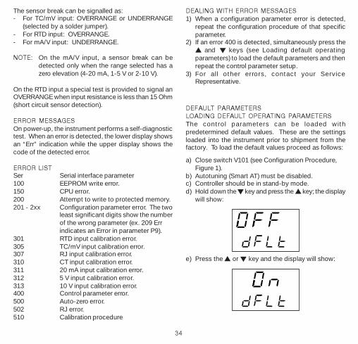
ERROR MESSAGESOn power-up, the instrument performs a self-diagnostictest. When an error is detected, the lower display showsan “Err” indication while the upper display shows thecode of the detected error.
ERROR LISTSer Serial interface parameter100 EEPROM write error.150 CPU error.200 Attempt to write to protected memory.201 - 2xx Configuration parameter error. The two
least significant digits show the numberof the wrong parameter (ex. 209 Errindicates an Error in parameter P9).
301 RTD input calibration error.305 TC/mV input calibration error.307 RJ input calibration error.310 CT input calibration error.311 20 mA input calibration error.312 5 V input calibration error.313 10 V input calibration error.400 Control parameter error.500 Auto-zero error.502 RJ error.510 Calibration procedure
DEALING WITH ERROR MESSAGES1) When a configuration parameter error is detected,
repeat the configuration procedure of that specificparameter.
2) If an error 400 is detected, simultaneously press thes and t keys (see Loading default operatingparameters) to load the default parameters and thenrepeat the control parameter setup.
3) For all other errors, contact your ServiceRepresentative.

35
g) Press the FUNC key; the display will show:
This indicates that the loading procedure has beeninitiated. After about 3 seconds the loading procedureis complete and the instrument reverts to the “normaldisplay mode.” The following is a list of the defaultoperating parameters loaded during the procedure:
DEFAULT OPERATING PARAMETER LISTParam Default ValueSP Minimum of range valueSnrt Disabledn.RSt OFFSP2 Minimum of rangennn OFFAL1, AL2 Minimum of range (process alarms)
0 (deviation or band alarms)HSA1, HAS2 0.1%Pb 4.0%hys 0.5%tl 4.00 (4 minutes)td 1.00 (1 minute)IP 30%CY1 15 seconds (relay output)
4 seconds (SSR output)CY2 10 seconds for P8 = Alr
4 seconds for P8 = OlL2 seconds for P8 = H2O
rC 1.00 for P8 = Alr0.80 for P8 = OlL0.40 for P8 = H2O
OLAP 0rL Initial scale valuerH Full scale value
DEFAULT CONFIGURATION PARAMETERSThe configuration parameters can be loaded withpredetermined default values. These are the settingsloaded into the instrument prior to shipment from thefactory. To load the default values proceed as follows:
a) Open switch V101 (see Configuration Procedure,Figure 1).
b) The upper display will show:
c) Press the t key; the lower display will show thefirmware version.
Grd1 Infinite (step transfer)Grd2 Infinite (step transfer)OLH 100%tOL InfiniteHbd 50% of the full scaleSCA 100% of full scalemP 25% of the output per second

36
d) Still holding the t key, press the s key. The displaywill show:
e) Use the s key to select the desired defaultparameters (see table).
g) Press the FUNC key; the display will show:
This indicates that the loading procedure has beeninitiated. After about 3 seconds the loading procedureis complete and the instrument reverts to the “COnF”display. The following table is a list of the defaultconfiguration parameters loaded during the procedure:
.ARAP 1elbaT 2elbaT
naeporuE ASU
1rES orE orE
2rES 1 1
3rES 02.91 02.91
4rES E7 E7
1P 3 02
2P .---- .----
3P 0 0
4P 004 0001
5P LEr LEr
6P VEr VEr
7P 1 1
8P rlA rlA
9P .A.H .A.H
01P FFO FFO
11P 01 01
21P 0 0
31P .A.H .A.H
41P .trPO .trPO
51P 0 0
61P 1.0 1.0
71P 0 0
81P 0 0
91P VEr VEr
02P FFO FFO
12P VEr VEr
22P FFO FFO
32P 0 0

37
52P NO NO
62P NO NO
72P 2 2
82P FFO FFO
92P 03 03
03P 5.1 5.1
13P 0.1 0.1
23P 05.00 05.00
33P 0 0
53P 01nt 03nt
63P LF.On LF.On
73P 0 0
83P 0 0
93P 01 01
04P diP diP
14P pS.nF pS.nF
24P 0 0
SPECIFICATIONS
GeneralCase: Polycarbonate dark grey color (RAL 7043); self-
extinguishing degree; V-0 according to UL94.Front Protection: Designed, tested for IP65 and NEMA
4X for indoor locations when panel gasket isinstalled. Tests were performed in accordance withCEI70-1 and NEMA 250-1991 Std.
Installation: Panel mounting, or wall mounting or railmounting.
Rear Terminal Block: Screw terminals for cables 0.25to 2.5 mm2 or from AWG 22 to AWG 14.
Dimensions: See illustrations elswhere in this manual.Weight: 250 g.Power Supply: 100 to 240 Vac, 50/60 Hz., -15% to
10% of nominal value; 24 Vac/Vdc ±10% nominalvalue.
Power Consumption: 8 VA maximum.Insulation Resistance: > 100 M ohms according to IEC
1010-1.Dielectric Strength: 1500 V rms according to IEC
1010-1.Display Updating Time: 500 ms.Sampling Time: 250 ms for linear inputs; 500 ms for
TC and RTD inputs.Resolution: 30000 counts.Accuracy: ±0.2% fsv; ±1 digit @ 25°C ambient
temperature.Common Mode Rejection: 120 dB @ 50/60 Hz.Normal Mode Rejection: 60 dB @50/60 Hz.Electromagnetic Compatibility and Safety
Requirements: Conforms to council directives 89/336/EEC (reference harmonized standard EN-50081-2 and EN-50082-2) and to council directives73/23/EEC and 93/68/EEC (reference harmonizedstandard En 61010-1).
Installation Category: II.Temperature Drift (reference junction excluded): <200
ppm/°C of span for mV and TC ranges 1, 3, 5, 6, 19,

38
20, 21, 22. <300 ppm/°C of span for mA/V. <400ppm/°C of span for RTD range 10, 26, and TC range0, 2, 4, 27,28. <500 ppm/°C for RTD range 9 andTC ranges 7, 8, 23, 24. <800 ppm/°C of span forRTD range 25.
Operating Temperature: 0 to 50°C (32 to 122°F).Storage Temperature: -20 to 70°C (-4 to 158°F).Humidity: 20% to 85% rh, non-condensing.Protections: Watchdog circuit for automatic restart;
DIP switch against tampering of configuration andcalibration parameters.
InputsThermocouple types J, K, L, N, R, S, T:°C°F: selectable.External Resistance: 100 ohms max., maximum error
0.1% of span.Burn Out: Shown as overrange condition (standard).
Possible to obtain underrange indication by cut andshort.
Reference Junction: Automatic compensation from 0to 50°C.
Reference Junction Accuracy: 0.1°C/°C.Input Impedance: > 1 megohms.Calibration: According to IEC 584-1 and
DIN 43710-1977. Standard Ranges:Type Range °C Range °FL 0 0 to 400.0L 1 0 to 900 19 0 to 1650J 2 -100.0 to 400.0J 3 -100 to 1000 20 -150 to 1830K 4 -100.0 to 400.0K 5 -100 to 1370 21 -150 to 2500N 6 -100 to 1400 22 -150 to 2550R 7 0 to 1760 23 0 to 3200S 8 0 to 1760 24 0 to 3200T 27 -199.9 to 400.0 28 -330 to 750
RTD (Resistance Temperature Detector)Input: Pt 100 ohms, 3 wire connection.Input Circuit: Current injection.°C/°F Selection: Via front keys, or serial link.Line Resistance: Automatic compensation up to 20
ohms/wire with no measurable error.Calibration: According to DIN 43760.Burnout: Up scale. A special test is provided to signal
overrange when input resistance is less than 15ohms.
Standard Ranges: Pt.100 ohms, DIN 437609 -199.9 to 400.0 °C
10 -200 to 800 °C25 -199.9 to 400.0 °F26 -330 to 1470 °F
LinearReadout: Keyboard programmable between -1999
and 4000.Decimal Point: Programmable in any position.Burn Out: Controller shows burn out condition as
underrange condition for 4 to 20 mA, 1 to 5 V, and 2to 10 V input types. It shows burn out asunderrange or overrange (selectable by solderingjumper) for 0 to 60 mV and 12 to 60 mV input types.No indication is available for 0 to 20 mA, 0 to 5 V,and 0 to 10 V input types.
Accuracy: 0.2% + 1 digit @ 25°C.Impedance: >1 M ohms 0 to 60 mV (11)
>1 M ohms 12 to 60 MV (12)<5 ohms 0 to 20 mA (13)<5 ohms 4 to 20 mA (14)
>200 k ohms 0 to 5 V (15)>200 k ohms 1 to 5 V (16)>400 k ohms 0 to 10 V (17)>400 k ohms 2 to 10 V (18)

39
LogicController is equipped with one input from voltagefree contact for setpoint selection.
Contact Open: Main setpoint.Contact Closed: Auxiliary setpoint.
Use an external dry contact capable of switching0.5 mA, 5 Vdc. Controller needs 100 ms torecognize a contact status variation. The logic inputis not isolated by the measuring input. This optionalfunction is alternative to amp sensing transformerinput.
Current TransformerControllers with this feature can detect and signal apossible failure of the line driven by OUT 1.
Input Range: 50 mAacScaling: Programmable from 10 Amps to 100 Amps in
1 Amp steps.Resolution: 0.1 Amp for full scale up to 20 Amps; 1
Amp for full scale from 21 to 100 Amps.Minimum duration of on/off period to perform
measurement: 400 ms. This function excludes thelogic input (external setpoint selection).
SetpointsThis controller allows use of two setpoints: SP andSP2. Setpoint selection is possible only by logicinput.
Setpoint Transfer: From one setpoint to another, orbetween two different setpoint values accomplishedby a step transfer or by a ramp with two differentprogrammable rates of change (ramp up and rampdown).
Slope Value: 1 to 100 engineering units/minute orstep.
Setpoints Limiter: RLO and RHI parameters,programmable.
Control ActionsControl Action: PID + SMART.Type: One (heating or cooling) or two (heating and
cooling) control outputs.Proportional Band (Pb): Range from 1.0 to 100.0% of
the input span for process with one control output;from 1.5 to 100.0% of the input span for processwith two control outputs. When Pb = 0, controlaction is on/off.
Hysteresis (for on/off control action): from 0.1% to10.0% of the input span.
Integral Time (ti): From 1 second to 20 minutes, orexcluded.
Derivative Time (td): From 0 seconds to 10 minutes. Ifzero value is selected, the derivative action isexcluded.
Integral Pre-load: From 0.0 to 100.0% for one controloutput; from -100.0 (cooling) to 100.0% (heating) fortwo control outputs.
Autotune (SMART): Keyboard enabling/disabling.Auto/Manual: Keyboard selectable.Auto/Manual Transfer: Bumpless method type.Indicator: “MAN” off in auto mode; lit in manual mode.
OutputsControl Output Updating Time: 250 ms for linear
output; 500 ms for TC or RTD.Action: Direct/reverse programmable from front
keyboard.Output Level Indication: Separate displays for output
1 (heating) level and output 2 (cooling) level.Output Status Indication: Two indicators – OUT 1 and
OUT 2. Each is lit when its respective output is on.Output Level Limiter: 0 to 100% for one control
medium; -100 to 100% for two control mediums.This function may operate at controller start up for aprogrammable time (to avoid thermal shock and/orpre-heating the plant). Otherwise, it can be enabledby an external contact.

40
Cycle Times: Outputs 1 and 2 each programmable for1 to 200 seconds.
Relative Cooling Gain: Programmable from 0.20 to1.00.
Overlap/Deadband: Programmable from -20% to50% of the proportional band.
Output 1Type: Relay, SPDT contact. NO or NC selectable by
jumper.Contact Rating: 3 Amp @ 250 Vac on resistive load.Function: Programmable as heating or cooling output.Output Cycle Time: Programmable from 1 to 200
seconds.
Output 2Type: Relay, SPST contact.Contact Rating: 2 Amp @ 250 Vac on resistive load.Function: Programmable as cooling control output, or
alarm 1 output.Output Cycle Time: Programmable from 1 to 200
seconds when used as a control output.
Output 3Type: Relay, SPST contact.Contact Rating: 2 Amp @ 250 Vac on resistive load.Function: Alarm 2.
AlarmsAction: Direct or reverse acting.Functions: Each alarm can be configured for process,
band or deviation.Reset: Automatic or manual programmable on each.Stand-by (mask); Each alarm can be configured with
or without mask function. This function allows youto preclude false indication at controller start up, orafter a setpoint change.
Process AlarmOperating Mode: high or low programmable.Setpoint: Programmable in engineering units within
the input span.Hysteresis: Programmable from 0.1% to 10.0% of the
input span (P4 - P3).Band AlarmOperating Mode: Inside or outside programmable:Setpoint: Programmable from 0 to 500 units.Hysteresis: Programmable from 0.1% to 10.0% of the
input span.Deviation AlarmOperating Mode: High or low programmable.Setpoint: Programmable from -500 to 500 units.Hysteresis: Programmable from 0.1% to 10.0% of the
input span.
Serial Communications InterfaceType: RS-485.Protocol: MODBUS, JBUS, proprietary polling/
selecting.Baud: Programmable from 600 to 19200.Byte Format: 7 or 8 bit, programmable.Parity: Even, odd, or none programmable.Stop Bits: oneAddress: 1 to 95 for proprietary protocol; 1 to 255 for
other protocols.Output Voltage Levels: According to EIA standard.

41
CALIBRATION
Calibration parameters are logically divided into groupsof two parameters each - minimum range value andmaximum range value. A calibration check is providedafter entering the values of each group. A calibrationcheck can be initiated without making an entry: pressthe FUNC key to advance to the desired calibration check(t. - rj. - P. - nA. - 5V. - 10V. - Ct.).
Before beginning calibration, be sure internal switch V101(see configuration procedure, Figure 1) is open.
WARNING: Perform the calibration procedure accordingto J106 jumper positions as shown below. Otherwise,stored calibration values may be lost.
tupnIepyT
601J
2-1 4-3 6-5 8-7 01-9
DTR-CT nepo esolc nepo nepo nepo
Vm06 nepo esolc nepo nepo nepo
V5 esolc nepo esolc nepo nepo
V01 nepo nepo esolc nepo nepo
Am02 nepo nepo nepo esolc esolc
a)The instrument should be mounted in its case in orderto keep the internal temperature constant.
b) Ambient temperature should be stable. Avoid driftdue to air conditioning or other mechanical devices.
c)Relative humidity should not exceed 70%.d) Minimum warm up time should be at least 20 minutes.e)Operate as much as possible in a noise free
environment.f) During calibration, connect one input at a time to the
rear terminal block.
CALIBRATION PARAMETERS
Following is a complete list of calibration symbols:Code ParametertL TC Input Minimum Range ValuetH TC Input Maximum Range Valuet. TC Input CheckrJ Cold Junction CompensationrJ. Cold Junction Compensation CheckPL RTD Input Minimum Range ValuePH RTD Input Maximum Range ValueP. RTD Input ChecknAL Current Input Minimum Range ValuenAH Current Input Maximum Range ValuenA. Current Input Check5VL Volt Minimum Range Value5VH Volt Maximum Range Value5V. Volt Input Check10VL Volt Minimum Range Value10VH Volt Maximum Range Value10V. Volt Input CheckCt.L Current transformer minimum range valueCt.H Current transformer maximum range valueCt. Current transformer input check
g) Use calibrators with the following:AccuracyTC Input: ±0.005% output
±0.001% range±5 microvolt
RTD Input: ±0.02%±0.0025 ohms/decade
CJ Compensation: Better than 0.1 °CCurrent Transformer: 0.1 mA Ac rms
ResolutionTC Input: 1 microvoltRTD Input: 10 milliohmCJ Compensation: Better than 0.1 °CCurrent Transformer: 0.1 mA ac rms

42
PROCEDURE
Switch on the instrument; the display will show “COnF”.Press the s key and the display will show “CAL”. Pressthe “FUNC” key to start the calibration process.Repeatedly press the FUNC key until the desiredcalibration (parameter) code appears.
The lower display will show the parameter code whilethe upper display shows “ON” or “OFF”.
Use the s and t keys to select between ON and OFF.To go to the next parameter without modifying thecalibration, press the FUNC key when the display shows“OFF”.
To start parameter calibration, press the FUNC key whenthe display shows “ON”.
NOTE: Press the MAN key to display the previousparameter without storing the new calibration.
ENTERING CALIBRATION VALUES
TL TC INPUT MINIMUM RANGE VALUEa) Connect calibrator and instrument as shown below.
Panel Mount Controller
10
9
+
-
15
11 T/C : J, K , L, N, T
14 T/C: R , S
+
-Wall orRailMount
b) The upper display shows “OFF”, the lower displayshows “tL”.
c) Set the calibrator to 0.000 mV.d) Press the s or t key; the display changes to “ON”.e) After a few seconds, start calibration by pressing the
FUNC key. The decimal point of the least significantdigit will light to indicate the instrument is performingthe calibration. When calibration is complete, theinstrument will proceed to the next parameter.
TH TC INPUT MAXIMUM RANGE VALUEa) The upper display shows “OFF”, the lower display
shows “tH”.b) Set the calibrator to 60.000 mV.c) Press the s or t key; the display changes to “ON”.c) After a few seconds, start calibration by pressing the
FUNC key. The decimal point of the least significantdigit will light to indicate the instrument is performingthe calibration. When calibration is complete, theinstrument will proceed to the TC input check.
T. TC INPUT CHECKThe display will show ”t.” followed by a number showingthe measured value in counts. The calibration for “tH” iscorrect if the indication is “t. 3 0000” ±10 counts.
a) Check the “Minimum Range” calibration (seeparameter tL) by setting the calibrator to 0.000 mV -the readout must be equal to “t. 0 0000” ±10 counts
b) Check linearity at half scale by setting 30.000 mV onthe calibrator. The readout must be “t. 1 5000” ±10counts.
c) Check the “Maximum Range” calibration by settingthe calibrator to 60.000 mV - the readout must beequal to “t. 3 0000” ±10 counts
d) Press the FUNC key and the instrument will proceedto cold junction compensation.

43
PL RTD INPUT MINIMUM RANGE VALUEa) Connect a resistor box and the instrument as shown
below.
Panel Mount Controller
10
8
9
15
14
16
b) The upper display shows “OFF”, the lower displayshows “PL”.
c) Set 0.000 ohms on the resistor box.d) Press the s or t key; the display changes to “ON”.e) After a few seconds, start calibration by pressing the
FUNC key. The decimal point of the least significantdigit will light to indicate the instrument is performingthe calibration. When calibration is complete, theinstrument will proceed to the next parameter.
RJ COLD JUNCTION COMPENSATIONNOTE: Make sure “tL” and “tH” are correctly calibrated
before attempting “rJ” calibration.a) Measure the temperature close to terminals 9 and 10
using an appropriate instrument, as shown below.
Panel Mount Controller
10
9
Measuring Device
+
-
15
11 T/C: J , K , L , N, T
14 T/C : R , S
+
-
Mea
surin
gD
evic
e
b) Wait a few minutes to allow temperature stabilizationof the entire system (compensation cable, sensor,calibrator and instrument).
c) Using the s and t keys, make the readout valueequal to the temperature measured by the measuringdevice in tenths of a °C.
d) After a few seconds, start calibration by pressing theFUNC key. The decimal point of the least significantdigit will light to indicate the instrument is performingthe calibration. When calibration is complete, theinstrument will proceed to the cold junctioncompensation check.
RJ. COLD JUNCTION COMPENSATION CHECKThe display will show “rJ.” and the temperature in tenthsof a degree, measured by the CJ compensator. Checkthat the display readout is equal to the value read by themeasuring device.
Wall orRailMount
Wall orRailMount
Press the FUNC key, the instrument will proceed to RTDinput minimum range value.

44
PH RTD INPUT MAXIMUM RANGE VALUEa) The upper display shows “OFF”, the lower display
shows “PH”.b) Set the resistor box to 375.000 ohms.c) Press the s or t key; the display changes to “ON”.d) After a few seconds, start calibration by pressing the
FUNC key. The decimal point of the least significantdigit will light to indicate the instrument is performingthe calibration. When calibration is complete, theinstrument will proceed to the RTD input check.
P. RTD INPUT CHECKThe display shows “P.” followed by a number showingthe measured value in counts. The calibration for “PH”is correct if the indication is “P. 3 0000” ±10 counts.
a) Check the “Minimum Range” calibration (linear) bysetting 0.000 ohms (see parameter PL) on theresistance box; the readout should be “P. 0 0000”±10 counts.
b) Check the linearity at half scale calibration by setting125.000 ohms on the resistance box; the readoutshould be “P. 1 0190” ±10 counts.
c) Check the “Maximum Range” calibration by setting375.000 ohms on the resistance box; the readoutshould be “P. 3 0000” ±10 counts.
d) Press the FUNC key and the instrument will proceedto the current input minimum range calibration.
NAL CURRENT INPUT MINIMUM RANGE VALUEa) Connect the calibrator and instrument as shown below.
Panel Mount Controller
10
9
+
-
15
14
+
-
b) The upper display shows “OFF”, the lower displayshows “nAL”.
c) Set calibrator to 0.000 mA (even if the minimum rangevalue is 4 mA).
d) Press the s or t key; the display changes to “ON”.e) After a few seconds, start calibration by pressing the
FUNC key. The decimal point of the least significantdigit will light to indicate the instrument is performingthe calibration. When calibration is complete, theinstrument will proceed to the next parameter.
NAH CURRENT INPUT MAXIMUM RANGE VALUEa) The upper display shows “OFF”, the lower display
shows “nAH”.b) Set calibrator to 20.000 mA.c) Press the s or t key; the display changes to “ON”.d) After a few seconds, start calibration by pressing the
FUNC key. The decimal point of the least significantdigit will light to indicate the instrument is performingthe calibration. When calibration is complete, theinstrument will proceed to the current input check.
NA. CURRENT INPUT CHECKThe display shows “nA.” followed by a number showingthe measured value in counts. The calibration for “nAH”is correct if the indication is “nA. 3 0000” ±10 counts.
Wall orRailMount

45
5VL 5 VOLT INPUT MINIMUM RANGE VALUEa) Connect the calibrator and instrument as shown
below.
Panel Mount Controller
10
9
+
-
15
14
+
-
b) The upper display shows “OFF”, the lower displayshows “5VL”.
c ) Set calibrator to 0.000 V (even if the minimum rangevalue is 1 V).
d) Press the s or t key; the display changes to “ON”.e) After a few seconds, start calibration by pressing the
FUNC key. The decimal point of the least significantdigit will light to indicate the instrument is performingthe calibration. When calibration is complete, theinstrument will proceed to the next parameter.
5VH 5 VOLT INPUT MAXIMUM RANGE VALUEa) The upper display shows “OFF”, the lower display
shows “5VH”.b) Set calibrator to 5 V.c) Press the s or t key; the display changes to “ON”.d) After a few seconds, start calibration by pressing the
FUNC key. The decimal point of the least significantdigit will light to indicate the instrument is performingthe calibration. When calibration is complete, theinstrument will proceed to the 5 volt input check.
5V. 5 VOLT INPUT CHECKThe display shows “5V.” followed by a number showingthe measured value in counts. The calibration for “5VH”is correct if the indication is “5V. 3 0000” ±10 counts.
a) Check the “Minimum Range” calibration (linear) bysetting 0.000 V (see parameter 5VL) on the calibrator;the readout should be “5V. 0 0000” ±10 counts.
b) Check the linearity at half scale by setting 2.500 V onthe calibrator; the readout should be “5V. 1 5000” ±10counts.
c) Check the “Maximum Range” calibration by setting5.000 V on the calibrator; the readout should be “5V.3 0000” ±10 counts.
d) Press the FUNC key and the instrument will proceedto 10 volt input minimum range value calibration.
Wall orRailMount
a) Check the “Minimum Range” calibration (linear) bysetting 0.000 mA (see parameter nAL) on the calibrator;the readout should be “nA. 0 0000” ±10 counts.
b) Check the linearity at half scale by setting 10.000 mAon the calibrator; the readout should be “nA. 1 5000”±10 counts.
c) Check the “Maximum Range” calibration by setting20.000 mA on the calibrator; the readout should be“nA. 3 0000” ±10 counts.
d) Press the FUNC key and the instrument will proceedto 5 volt input minimum range value calibration.

46
CT.L CURRENT TRANSFORMER MINIMUMRANGE VALUEa) Connect the calibrator and instrument as shown
below.
Panel Mount Controller
14
15
≈
≈
12
13
Wall orRailMount
10VL 10 VOLT INPUT MINIMUM RANGE VALUEa) Connect the calibrator and instrument as shown
below.
Panel Mount Controller
10
9
+
-
15
14
+
-
b) The upper display shows “OFF”, the lower displayshows “10VL”.
c) Set calibrator to 0.000 V (even if the minimum rangevalue is 2 V).
d) Press the s or t key; the display changes to “ON”.e) After a few seconds, start calibration by pressing the
FUNC key. The decimal point of the least significantdigit will light to indicate the instrument is performingthe calibration. When calibration is complete, theinstrument will proceed to the next parameter.
10VH 10 VOLT INPUT MAXIMUM RANGE VALUEa) The upper display shows “OFF”, the lower display
shows “10VH”.b) Set calibrator to 10 V.c) Press the s or t key; the display changes to “ON”.d) After a few seconds, start calibration by pressing the
FUNC key. The decimal point of the least significantdigit will light to indicate the instrument is performingthe calibration. When calibration is complete, theinstrument will proceed to the 10 volt input check.
Wall orRailMount
10V. 10 VOLT INPUT CHECKThe display shows “10V.” followed by a number showingthe measured value in counts. The calibration for “10VH”is correct if the indication is “10V.3 0000” ±10 counts.
a) Check the “Minimum Range” calibration (linear) bysetting 0.000 V (see parameter 10VL) on the calibrator;the readout should be “10V.0 0000” ±10 counts.
b) Check the linearity at half scale by setting 5.000 V onthe calibrator; the readout should be “10V.1 5000”±10 counts.
c) Check the “Maximum Range” calibration by setting10.000 V on the calibrator; the readout should be“10V.3 0000” ±10 counts.
d) Press the FUNC key and the instrument will proceedto current transformer minimum range value calibration.

47
c ) Check the “Maximum Range” calibration by setting50.000 mA on the calibrator; the readout should be“Ct. 0 1000” ±10 counts.
d) Press the FUNC key.
This completes the calibration procedure. To enter theconfiguration procedure press the s key, the display willshow “CnF”. If configuration and calibration are complete,switch the instrument off and close the switch V101 (seeconfiguration procedure, Figure 1).
MAINTENANCE1. Disconnect the power from the power supply
terminals and relay output terminals.2. Remove the instrument from its case.3. Using a vacuum cleaner or a compressed air jet (max.
3 kg/cm2) remove dust and dirt which may be presenton the louvers and on the internal circuits, beingcareful to not damage the electronic components.
4. Clean external plastic or rubber parts with a clothmoistened with ethyl alcohol (pure or denatured)[C2H5OH]; or isopropyl alcohol (pure or denatured)[(CH3)2 CHOH]; or water [H2O].
5. Verify that there are no loose terminals.6. Before re-inserting the instrument in its case, be sure
it is dry.7. Re-insert the instrument and turn it on.
b) The upper display shows “OFF”, the lower displayshows “Ct.L”.
c) Set calibrator to 0.000 mA.d) Press the s or t key; the display changes to “ON”.e) After a few seconds, start calibration by pressing the
FUNC key. The decimal point of the least significantdigit will light to indicate the instrument is performingthe calibration. When calibration is complete, theinstrument will proceed to the next parameter.
CT.H CURRENT TRANSFORMER MAXIMUMRANGE VALUEa) The upper display shows “OFF”, the lower display
shows “Ct.H”.b) Set calibrator to 50.000 mA r.m.s.c) Press the s or t key; the display changes to “ON”.d) After a few seconds, start calibration by pressing the
FUNC key. The decimal point of the least significantdigit will light to indicate the instrument is performingthe calibration. When calibration is complete, theinstrument will proceed to the Current transformerinput check.
CT. CURRENT TRANSFORMER INPUT CHECKThe display shows “Ct.” followed by a number showingthe measured value in counts. The calibration for “Ct.H”is correct if the indication is “Ct. 0 1000” ±10 counts.
a) Check the “Minimum Range” calibration by setting0.000 mA (see parameter 10VL) on the calibrator; thereadout should be “Ct. 0 0000” ±10 counts.
b) Check the linearity at half scale by setting 25.000 mAon the calibrator; the readout should be “Ct. 0 0500”±10 counts.

Barber-Colman CompanyIndustrial Instruments Division1354 Clifford AvenueP.O. Box 2940Loves Park, IL U.S.A. 61132-2940
Telephone +1 800 232 4343Facsimile +1 815 637 5341http://www.barber-colman.com
A Siebe Group CompanyCopyright © 1997 Barber-Colman Company.