instruction manual - hobbicomanuals.hobbico.com/hca/hcaa2511-manual.pdf · instruction manual will...
TRANSCRIPT

SPECIFICATIONS
Entire Contents © Copyright 2009 HCAA2511 Mnl
Wingspan: 47 in[1195 mm]
WingArea:
390 sq in[25.2 dm2]
Weight: 27 oz[770 g]
WingLoading:
10 oz/sq ft[31 g/dm2]
Length: 39 in[990 mm]
Radio:4-ChannelTactic™ TTX4042.4GHz (included)with receiver &4 micro servos
READ THROUGH THIS MANUAL BEFORE STARTING CONSTRUCTION. IT CONTAINS IMPORTANTINSTRUCTIONS AND WARNINGS CONCERNING THE ASSEMBLY AND USE OF THIS MODEL.
WARRANTYHobbico® guarantees this kit to be free from defects in both material and workmanship at the date of purchase. This warranty does not cover any component parts damaged by use or modification. In no case shall Hobbico’s liability exceed the original cost of the purchased kit. Further, Hobbico reserves the right to change or modify this warranty without notice.
In that Hobbico has no control over the final assembly or material used for final assembly, no liability shall be assumed nor accepted for any damage resulting from the use by the user of the final user-assembled product. By the act of using the user-assembled product, the user accepts all resulting liability.
If the buyer is not prepared to accept the liability associated with the use of this product, the buyer is advised to return
this kit immediately in new and unused condition to the place of purchase.
To make a warranty claim send the defective part or item to Hobby Services at the address below:
Hobby Services3002 N. Apollo Dr. Suite 1Champaign IL 61822 USA
Include a letter stating your name, return shipping address, as much contact information as possible (daytime telephone number, fax number, e-mail address), a detailed description of the problem and a photocopy of the purchase receipt. Upon receipt of the package the problem will be evaluated as quickly as possible.
I N S T R U C T I O NM A N U A L
™

2
TABLE OF CONTENTS
INTRODUCTION . . . . . . . . . . . . . . . . . . . . . . . . . . . . . . . . 2 AMA . . . . . . . . . . . . . . . . . . . . . . . . . . . . . . . . . . . . . . . 2SAFETY PRECAUTIONS . . . . . . . . . . . . . . . . . . . . . . . . . 2ADDITIONAL ITEMS REQUIRED . . . . . . . . . . . . . . . . . . . 3OPTIONAL BATTERIES & CHARGERS. . . . . . . . . . . . . . 3ORDERING REPLACEMENT PARTS . . . . . . . . . . . . . . . . 3KIT CONTENTS . . . . . . . . . . . . . . . . . . . . . . . . . . . . . . . . . 4KIT INSPECTION. . . . . . . . . . . . . . . . . . . . . . . . . . . . . . . . 5ASSEMBLE THE MODEL . . . . . . . . . . . . . . . . . . . . . . . . . 5 Assemble the Wings . . . . . . . . . . . . . . . . . . . . . . . . . . 5 Install the Tail . . . . . . . . . . . . . . . . . . . . . . . . . . . . . . . . 5 Hook up the Controls . . . . . . . . . . . . . . . . . . . . . . . . . . 6 Final Assembly. . . . . . . . . . . . . . . . . . . . . . . . . . . . . . 10 Balance the Model (C.G.). . . . . . . . . . . . . . . . . . . . . . 12PREFLIGHT . . . . . . . . . . . . . . . . . . . . . . . . . . . . . . . . . . . 12 Identify Your Model . . . . . . . . . . . . . . . . . . . . . . . . . . . 12 Charge the Battery. . . . . . . . . . . . . . . . . . . . . . . . . . . 12 Balance Propellers. . . . . . . . . . . . . . . . . . . . . . . . . . . 12MOTOR SAFETY PRECAUTIONS . . . . . . . . . . . . . . . . . 13LITHIUM BATTERY HANDLING AND USAGE . . . . . . . . 13RADIO SYSTEM INSTRUCTIONS . . . . . . . . . . . . . . . . . 13FLYING YOUR SKYFLY MAX . . . . . . . . . . . . . . . . . . . . . 16 Find a Suitable Flying Site . . . . . . . . . . . . . . . . . . . . . 16 Perform a Range Check. . . . . . . . . . . . . . . . . . . . . . . 16 Monitor Your Flight Time. . . . . . . . . . . . . . . . . . . . . . . 16 Take Off . . . . . . . . . . . . . . . . . . . . . . . . . . . . . . . . . . . 17 Flying . . . . . . . . . . . . . . . . . . . . . . . . . . . . . . . . . . . . . 17 Landing . . . . . . . . . . . . . . . . . . . . . . . . . . . . . . . . . . . 18 Some Things You Will Learn About R/C Flying . . . . . 18AFTER EACH FLIGHT. . . . . . . . . . . . . . . . . . . . . . . . . . . 18REPAIRING YOUR MODEL . . . . . . . . . . . . . . . . . . . . . . . 18
INTRODUCTION
Thank you for purchasing the Flyzone SkyFly Max! This instruction manual will help set you on your way to learn to fl y. You’ve probably already noticed that the SkyFly Max is a little different from other trainers you’ve seen. It is, in fact, quite different! Many trainers in this class have 3-channel control – that is: Elevator, Rudder, and Throttle. Your new SkyFly Max has a full 4-channel control system. You get Elevator, Rudder, Throttle, and Ailerons, so your next steps can be into the more advanced airplanes you dream of. We give you the lightweight power of a brushless motor and a big capacity LiPo battery you can use in your next airplane, along with an innovative new Tactic 2.4GHz radio system. This has the added convenience of a wireless trainer function. You can even teach a friend to fl y after you’ve learned! We’ve packed the SkyFly Max with the features you’ll need to grow! We believe that you’ll like your new trainer so much that you’ll want to keep it around for years to come.
Although this is a trainer and is very resilient, you will need to seek the help of an experienced R/C pilot. Visit your local hobby shop or contact the AMA for a list of R/C fl ying fi elds and clubs in your area. We highly recommend that you
purchase a second Tactic TTX404 2.4GHz transmitter or fi nd a fl ying buddy that has a Flyzone SkyFly Max
For the latest technical updates or manual corrections to the Flyzone SkyFly Max visit the Hobbico® web site at www.hobbico.com. Open the “Airplanes” link, and then select the Flyzone SkyFly Max. If there is new technical information or changes to this model, a “tech notice” box will appear in the upper left corner of the page.
AMA
We urge you to join the AMA (Academy of Model Aeronautics) and a local R/C club. The AMA is the governing body of model aviation and membership is required to fl y at AMA clubs. Though joining the AMA provides many benefi ts, one of the primary reasons to join is liability protection. Coverage is not limited to fl ying at contests or on the club fi eld. It even applies to fl ying at public demonstrations and air shows. Failure to comply with the Safety Code (excerpts printed in the back of the manual) may endanger insurance coverage. Additionally, training programs and instructors are available at AMA club sites to help you get started the right way. There are over 2,500 AMA chartered clubs across the country. Contact the AMA at the address or toll-free phone number below.
Academy of Model Aeronautics5151 East Memorial DriveMuncie, IN 47302-9252Tele. (800) 435-9262Fax (765) 741-0057Or via the Internet at:http://www.modelaircraft.org
IMPORTANT!!! Two of the most important things you can do to preserve the radio controlled aircraft hobby are to avoid fl ying near full-scale aircraft and avoid fl ying near or over groups of people.
PROTECT YOUR MODEL, YOURSELF & OTHERS… FOLLOW THESE
IMPORTANT SAFETY PRECAUTIONS
1. Your SkyFly Max should not be considered a toy, but rather a sophisticated, working model that functions very much like a full-size airplane. Because of its performance capabilities, the SkyFly Max, if not assembled and operated correctly, could possibly cause injury to you or spectators and damage to property.
2. You must assemble the model according to the instructions. Do not alter or modify the model, as doing so may result in an unsafe or unfl yable model. In a few cases the instructions may differ slightly from the photos. In those instances the written instructions should be considered as correct.
3. If you are not an experienced pilot or have not fl own this type of model before, we recommend that you get
3
the assistance of an experienced pilot in your R/C club for your fi rst fl ights. If you’re not a member of a club, your local hobby shop has information about clubs in your area whose membership includes experienced pilots.
4. While this kit has been fl ight tested to exceed normal use, if the plane will be used for extremely high stress fl ying, such as racing, or if a motor larger than one in the recommended range is used, the modeler is responsible for taking steps to reinforce the high stress points and/or substituting hardware more suitable for the increased stress.
We, as the kit manufacturer, provide you with a top quality, thoroughly tested kit and instructions, but ultimately the quality and fl yability of your fi nished model depends on how you build it; therefore, we cannot in any way guarantee the performance of your completed model, and no representations are expressed or implied as to the performance or safety of your completed model.
ADDITIONAL ITEMS REQUIRED
In order to build your SkyFly Max, you will need to purchase some regular (foam safe not required) CA and have a few common household tools on hand. The following is a list of required and optional supplies and tools you will need:
Required Items
❏ 1/2 oz. [15g] Thin Pro™ CA (GPMR6001)❏ #1 Phillips Screw Driver❏ Scissors❏ Pliers, regular & needle-nose❏ Felt-Tipped Pen (TOPQ2510)
Optional Items
❏ 1/2 oz. [15g] Medium Pro CA+ (GPMR6007)❏ CA applicator tips (HCAR3780)❏ 2 oz. [60g] Foam Safe CA Activator (GPMR6035)❏ CA debonder (GPMR6039)❏ Great Planes® Pro Thread locker (GPMR6060)❏ #1 Hobby knife (HCAR0105)❏ #11 blades (5-pack, HCAR0211)❏ Masking tape❏ Great Planes Stick-on lead weights (GPMQ4485)
OPTIONAL BATTERIES & CHARGERS
To enjoy more fl ights, you may want to order a few more LiPo battery packs, a better charger and power supply. If you already have some LiPo battery packs, you may be able to use them in this airplane too. This model uses an 11.1V (3S) LiPo battery pack. Because this model’s motor draws about 15 amps, you will need to use a battery pack with the proper “C-rating.” We suggest using a battery no smaller than an 11.1V 1500mAh 15C LiPo and a battery no larger than an 11.1V 2200mAh 25C LiPo.
Replacement Battery
❏ Hobbico Flyzone 11.1V (3S) 1800mAh LiPo (HCAA3984)
Optional Batteries
❏ Hobbico Flyzone 11.1V (3S) 1800mAh LiPo (HCAA3840)
❏ 11.1V (3S) 1500mAh SuperTigre® LiPo (SUPP1040)❏ 11.1V (3S) 1800mAh SuperTigre LiPo (SUPP1050)
The batteries listed below will work with this model but you will also need to purchase the adapter listed.
❏ Deans® Ultra Male to SuperTigre® ESC Adapter (SUPM0040)
❏ 11.1V (3S) 1600mAh BP Series LiPo (GPMP0719)❏ 11.1V (3S) 1800mAh Power Series LiPo (GPMP0515)❏ 11.1V (3S) 2200mAh Power Series LiPo (GPMP0520)
ORDERING REPLACEMENT PARTS
Replacement parts for the Flyzone SkyFly Max are available using the order numbers in the Replacement Parts List that follows on page 4. The fastest, most economical service can be provided by your hobby dealer or mail-order company.
To locate a hobby dealer, visit the Hobbico web site at www.hobbico.com. Choose “Where to Buy” at the bottom of the menu on the left side of the page. Follow the instructions provided on the page to locate a U.S., Canadian or International dealer.
Parts may also be ordered directly from Hobby Services by calling (217) 398-0007, or via facsimile at (217) 398-7721, but full retail prices and shipping and handling charges will apply. Illinois and Nevada residents will also be charged sales tax. If ordering via fax, include a Visa® or MasterCard® number and expiration date for payment.
Mail parts orders Hobby Services and payments by 3002 N Apollo Drive, Suite 1 personal check to: Champaign IL 61822
Be certain to specify the order number exactly as listed in the Replacement Parts List. Payment by credit card or personal check only; no C.O.D.
If additional assistance is required for any reason contact Product Support by e-mail at [email protected], or by telephone at (217) 398-8970.

Order No. Description
NOTE
Replacement Parts List
Full-size plans are not available. You can download a copy of this manual at www.greatplanes.com.
HCAA3984
HCAA3985HCAA3986HCAA3987HCAA3988HCAA3989HCAA3990HCAA3991HCAA3992HCAA3993HCAA3994HCAA3995HCAA3996GPMM3318
TA C J 0403
TA C L 0624
Flyzone 1800mAh11.1V Lipo BatteryFuselageWing SetStabilizer and Boom SetVertical FinCanopy HatchServo HatchLanding Gear w/ WheelsBrushless Motor8x4 PropellerElectronic Speed ControlReplacement ServoRubber Band Set3S LiPo SmartBalancing ChargerTTX404 2.4Ghz 4Channel TransmitterTR624 2.4Ghz6 Channel Receiver
4
KIT CONTENTS
Kit Contents 1. Tactic TTX404 2.4GHz 2. (4) AA-batteries 3. Fuselage assembly factory-installed motor, battery hatch cover, servo hatch
cover, elevator-rudder servos/connectors, TR624 2.4GHz receiver, aileron Y-connector
4. Wing (L&R) factory-installed ailerons, aileron servos, pushrods 5. Horizontal stabilizer & tail boom (stab) factory-installed elevators and pushrods 6. Vertical stabilizer (fi n) factory-installed rudder 7. Main landing gear & wheels 8. Flyzone 1800mAh 11.1V LiPo battery 9. Battery charger w/AC connector, DC connector 10. Wing joiner 11. Propeller & prop adapter 12. (4) 8" [203mm] Rubber bands 13. 11-3/4" [300mm] Wing joining tape
Not Pictured Prop installation tool Elevator setup gauge 4" [102mm] Adhesive-backed hook & loop fastener material
1
6
2
4
9
1011
1213
8
7
3
5

5
KIT INSPECTION
Before starting to build, take an inventory of this kit to make sure it is complete, and inspect the parts to make sure they are of acceptable quality. If any parts are missing or are not of acceptable quality, or if you need assistance with assembly, contact Product Support. When reporting defective or missing parts, use the part names exactly as they are written in the Kit Contents list.
Hobbico Product Support Ph: (217) 398-8970, ext. 53002 N Apollo Drive, Suite 1 Fax: (217) 398-7721Champaign, IL 61822
E-mail: [email protected]
ASSEMBLE THE MODEL
IMPORTANT: DO NOT mount the propeller to the airplane yet. The setup procedures will require you to turn on the radio and motor system. A mounted propeller could cause damage or injury if the throttle is accidentally bumped or the servo reversing switch is actuated.
Assemble the Wings
❏ 1. Turn the right wing over so that the servo and linkage are facing toward you. Insert the wood wing joiner into the right wing so that the angled corners of the joiner face the top of the wing. Note: You will not be able to fully insert the joiner if you insert it upside down.
❏ 2. Slide the other wing onto the joiner until both wings meet.
❏ 3. Turn the wing over. Peel the backing paper off of the supplied 11-3/4" [300mm] piece of wing joining tape. Apply the tape so that it secures the plastic center wing piece to the right wing. Wrap the tape around the wing and trim off any excess tape with scissors.
Install the Tail
WARNING: Do not remove the pieces of tape that hold in the pushrods until you have connected the pushrods to the elevator and the rudder (see step 5 below). Otherwise, the pushrods may slip into the tail boom and will be diffi cult to re-route.
❏ 1. On the horizontal tail and tail boom assembly, point the tail boom away from you and the top of the horizontal tail facing up so that you are looking at the control linkages as shown. Attach the left pushrod clevis to the elevator control horn by inserting the clevis pin into the inner hole of the horn. Snap the clevis fi ngers together and slide the clevis retainer into position over the fi ngers as shown. Check to make sure that the connection is secure.
6
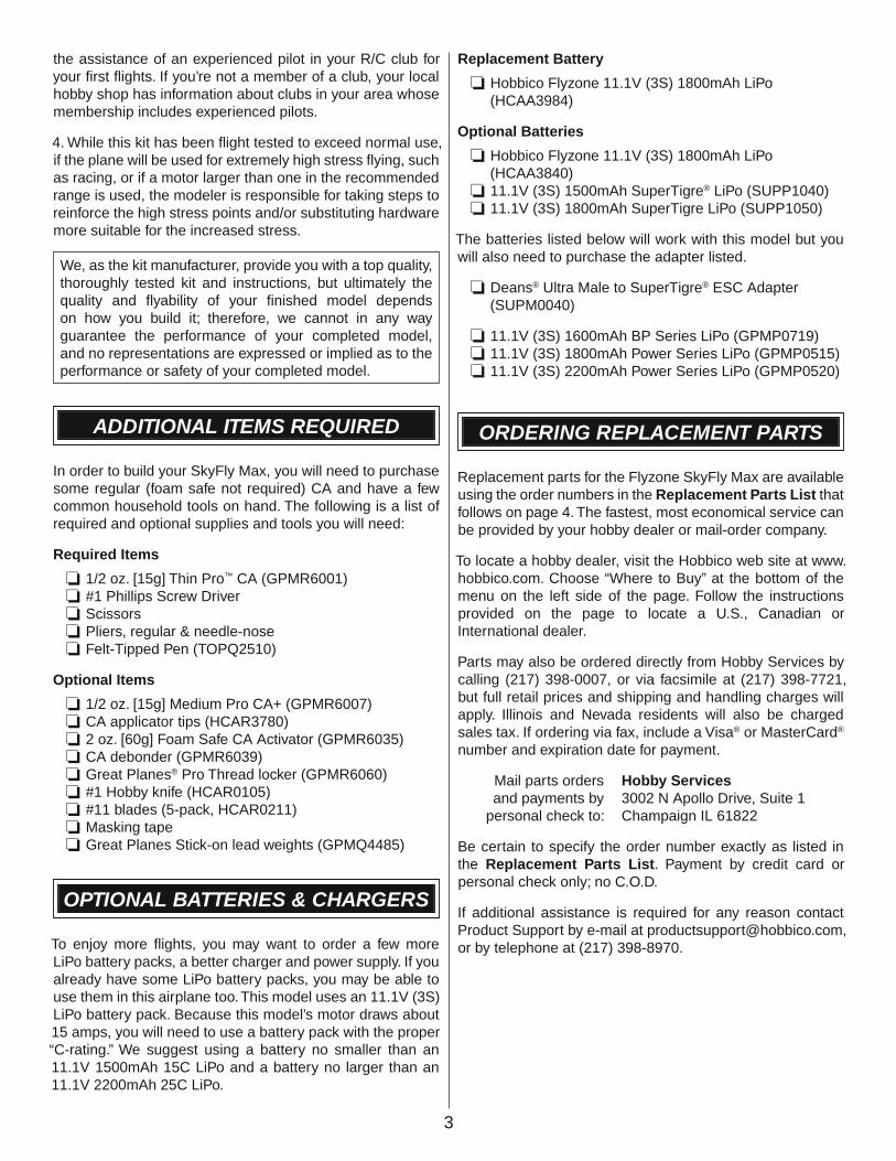
❏ 2. Fit the vertical tail tabs into the corresponding slots on the top side of the horizontal tail. Push the vertical tail in securely.
❏ 3. Run a thin bead of any thin CA adhesive (GPMR6001) into the tab joints on both sides of the tail. To speed up the cure of the CA, spray on a light mist of CA activator (GPMR6035).
❏ 4. Attach the rudder clevis to the outer hole of the rudder control horn. Snap the clevis fi ngers together and slide the clevis retainer into position. Check to make sure the connection is secure.
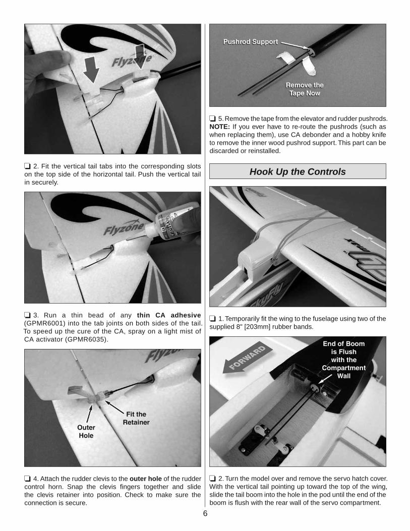
❏ 5. Remove the tape from the elevator and rudder pushrods. NOTE: If you ever have to re-route the pushrods (such as when replacing them), use CA debonder and a hobby knife to remove the inner wood pushrod support. This part can be discarded or reinstalled.
Hook Up the Controls
❏ 1. Temporarily fi t the wing to the fuselage using two of the supplied 8" [203mm] rubber bands.
❏ 2. Turn the model over and remove the servo hatch cover. With the vertical tail pointing up toward the top of the wing, slide the tail boom into the hole in the pod until the end of the boom is fl ush with the rear wall of the servo compartment.
7
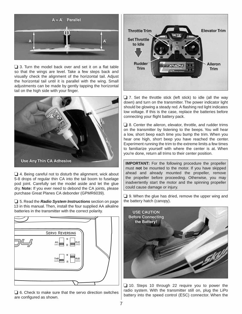
❏ 3. Turn the model back over and set it on a fl at table so that the wings are level. Take a few steps back and visually check the alignment of the horizontal tail. Adjust the horizontal tail until it is parallel with the wing. Small adjustments can be made by gently tapping the horizontal tail on the high side with your fi nger.
❏ 4. Being careful not to disturb the alignment, wick about 5-8 drops of regular thin CA into the tail boom to fuselage pod joint. Carefully set the model aside and let the glue dry. Note: If you ever need to debond the CA joints, please purchase Great Planes CA debonder (GPMR6039).
❏ 5. Read the Radio System Instructions section on page 13 in this manual. Then, install the four supplied AA alkaline batteries in the transmitter with the correct polarity.
❏ 6. Check to make sure that the servo direction switches are confi gured as shown.
❏ 7. Set the throttle stick (left stick) to idle (all the way down) and turn on the transmitter. The power indicator light should be glowing a steady red. A fl ashing red light indicates low voltage. If this is the case, replace the batteries before connecting your fl ight battery pack.
❏ 8. Center the aileron, elevator, throttle, and rudder trims on the transmitter by listening to the beeps. You will hear a low, short beep each time you bump the trim. When you hear one high, short beep you have reached the center. Experiment running the trim to the extreme limits a few times to familiarize yourself with where the center is at. When you’re done, return all trims to their center position.
❏ 9.
IMPORTANT: For the following procedure the propeller must not be mounted to the motor. If you have skipped ahead and already mounted the propeller, remove the propeller before proceeding. Otherwise, you may inadvertently start the motor and the spinning propeller could cause damage or injury.
When the glue has dried, remove the upper wing and the battery hatch (canopy).
❏ 10. Steps 10 through 22 require you to power the radio system. With the transmitter still on, plug the LiPo battery into the speed control (ESC) connector. When the

8
connection is made you will hear two beeps coming from the ESC. IMPORTANT: The beeping sound alerts you that the system has power and the motor is “armed.” This means whenever the throttle control stick is advanced, the propeller will turn. So later, when the propeller is mounted and you are ready to fl y, keep clear of the propeller while handling the model and do not inadvertently advance the throttle stick. If you do, the propeller will turn and damage or injury could be caused.
❏ 11. If you did not hear two beeps, you will need to perform the binding operation to set up a link between the transmitter (Tx) and receiver (Rx). Pull the receiver out of the plane and follow the Radio System Instructions section on page 13 to bind the receiver.
❏ 12. Turn the model over. With the trims centered, remove the retaining screw and remove the servo arm from the elevator servo (the servo on the airplane’s left side).
❏ 13. Carefully unscrew the pushrod locking screw from the screw-lock pushrod connector. You do not need to completely remove the screw – loosen it until you can slide the pushrod freely through the hole. Note: The screw threads are coated with thread locking compound, so you will need to grip the body of the screw-lock pushrod connector with a pair of needle-nosed pliers.
❏ 14. Slide the connector with the servo arm onto the elevator pushrod. Fit the servo arm to the splined servo output shaft so that the arm is about 90° with relation to the pushrod. Install the servo arm retaining screw. Note: If you can’t get the arm to get close to 90° by just matching up the splines, move the elevator trim up or down (up to 10 clicks) until you are satisfi ed. Setting the servo arm at 90° to the pushrod will give you equal control throw in both directions.

9
❏ 15. Tighten the pushrod locking screw so that it just contacts the pushrod. Back it off about 1/8th of a turn so that you can move the pushrod in the connector with some friction.
❏ 16. Place the centering mark of the elevator setup gauge directly over the elevator hinge line. Use the tool to set the elevator to 3° of up-elevator, with the elevator servo at neutral.
❏ 17. With the elevator in position, tighten the elevator servo’s pushrod locking screw securely. Check the elevator position with the elevator setup gauge to make sure that it didn’t slip when you tightened the locking screw.
❏ 18. Remove the servo arm from the rudder servo. Loosen the pushrod locking screw and fi t it to the rudder pushrod. Install the rudder servo arm as close to 90° to the pushrod as you can. Install the servo arm retaining screw.
❏ 19. Use a straight edge to set the rudder throw to zero degrees of travel. Tighten the rudder pushrod locking screw and check the rudder again to see that it is still centered.
❏ 20. Plug the two aileron servo leads into the Y-connector so that the orange wire on the servo lead is aligned with the orange wire on the Y-connector.

10
❏ 21. At this point, you will need to center the servos and adjust the aileron pushrods. Set the wing down fl at on the table with the bottom side up. With the radio still on, check to see that the servo arms are parallel with each other. If they are not, adjust the aileron trim on your transmitter until they are parallel like the second photo.
❏ ❏ 22. Loosen the aileron pushrod locking screws. Use a straight edge to set each aileron to zero travel (centered). With the aileron set, tighten the pushrod locking screw. Check to see that the aileron stayed centered and that the linkage is secure.
❏ 23. Unplug the LiPo battery and turn off your transmitter.
Final Assembly
❏ 1. Tuck the wires into the fuselage and fi t the wing. Install the wing using the four supplied 8" [203mm] rubber bands. Cross one pair as shown. Make sure that the wing is sitting correctly and that the servo wires are not caught between the wing saddle and the wing.
❏ 2. Snap the landing gear in place and fi t the servo hatch.
11
❏ 3. Separate the hook side from the loop side of the 4" [102mm] long piece of adhesive-backed hook & loop fastener material. Stick the loop side (fuzzy side) to the side of your battery that is opposite the leads. Stick the hook side to the fl oor of the battery compartment.
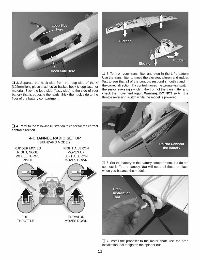
❏ 4. Refer to the following illustration to check for the correct control direction.
FULLTHROTTLE
RUDDER MOVESRIGHT, NOSE
WHEEL TURNSRIGHT
ELEVATORMOVES DOWN
RIGHT AILERONMOVES UP
LEFT AILERONMOVES DOWN
4-CHANNEL RADIO SET UP(STANDARD MODE 2)
❏ 5. Turn on your transmitter and plug in the LiPo battery. Use the transmitter to move the elevator, aileron and rudder. Test to see that all of the controls respond smoothly and in the correct direction. If a control moves the wrong way, switch the servo reversing switch in the front of the transmitter and check the movement again. Warning: DO NOT switch the throttle reversing switch while the model is powered.
❏ 6. Set the battery in the battery compartment, but do not connect it. Fit the canopy. You will need all these in place when you balance the model.
❏ 7. Install the propeller to the motor shaft. Use the prop installation tool to tighten the spinner nut.

12
Balance the Model (C.G.)
The C.G. (Center of Gravity) is the location on the wings, measured back from the leading edge on both sides of the fuselage, where the model balances. In addition to the control surface throws, the C.G. has a GREAT effect on the way the model fl ies. If the C.G. is too far aft (tail heavy), the model will be too responsive and diffi cult to control. If the C.G. is too far forward (nose-heavy), the model will be too stable and not responsive enough. Follow the instructions to make sure the model is balanced properly and the C.G. is in the correct location.
❏ 1. Turn the model over and mark the balance point on the bottom of each wing using a fi ne felt-tipped pen. Make a line on each wing that is 2-5/8" [67mm] back from the leading edge of the wing at the wing root (where the wing meets the fuselage). This is where you will balance your model.
❏ 2. With all parts in place including battery pack (do not plug it in), propeller, and canopy, lift up the model by placing your fi nger tips on the marks you just made or use a Great Planes C.G. Machine™ as shown here. The model should remain level. If the tail drops, nose weight must be added. If the nose drops, tail weight must be added. Note: While this model is essentially designed to balance out of the box, there can be variations from model to model so don’t skip this step. If you decide to use a different battery pack, you will also need to add weight.
If you need to add weight to balance your model, please purchase Great Planes Segmented Lead Weights (GPMQ4485).
PREFLIGHT
Identify Your Model
No matter if you fl y at an AMA sanctioned R/C club site or if you fl y somewhere on your own, you should always have your name, address, telephone number and AMA number on or inside your model. It is required at all AMA R/C club fl ying sites and AMA sanctioned fl ying events and simply a “good idea” even if fl ying somewhere else. Write this information on a strip of masking tape and place it on the inside of the battery hatch (or simply write the information directly on the battery hatch).
Charge the Battery
Be certain to refer to the instructions that accompany the charger to properly and safely charge the battery that goes in the model and powers the motor and controls.
When discharging the battery, DO NOT attempt to fully discharge the battery pack by repeatedly running the motor to the ESC’s low voltage cutoff. This will drastically shorten the life of your Lithium Polymer (LiPo) batteries and could cause the individual cells to become imbalanced.
Balance Propellers
The propeller supplied with this model should be balanced. If you need to replace it, follow these procedures to balance a new prop or if you experience more vibration than usual.
Carefully balance your propeller and spare propellers before you fl y. An unbalanced prop can be the single most signifi cant cause of vibration that can damage your model. Not only

13
will motor mounting screws and bolts loosen, possibly with disastrous effect, but vibration may also damage your radio receiver and radio gear.
We use a Top Flite® Precision Magnetic Prop Balancer (TOPQ5700) in the workshop and keep a Great Planes Fingertip Prop Balancer (GPMQ5000) in our fl ight box.
When you reinstall the propeller, make sure that the curved face of the prop faces the front of the airplane. This is also the side of the propeller that has number markings near the hub.
From time to time, check the motor to make sure that vibration has not loosened it on the mount. Tighten the motor mount set screw if it has loosened.
MOTOR SAFETY PRECAUTIONS
Failure to follow these safety precautions may result in severe injury to yourself and others.
Get help from an experienced pilot when learning to operate electric motors.
Use safety glasses when operating electric motors.
Do not operate the motor in an area of loose gravel or sand; the propeller may throw such material in your face or eyes.
Keep your face and body, as well as all spectators, away from the plane of rotation of the propeller as you operate the motor.
Keep these items away from the prop: loose clothing, shirt sleeves, sweat shirt strings, ties, scarves, long hair or loose objects such as pencils or screwdrivers that may fall out of shirt or jacket pockets into the prop.
The motor will arm when the throttle is at idle and the battery is plugged in. There is no further arming sequence for this model. Use extreme caution when working around an armed power system.
LITHIUM BATTERY HANDLINGAND USAGE
WARNING!! Read the entire instruction sheet included with the battery. Failure to follow all instructions could cause permanent damage to the battery and its surroundings, and cause bodily harm!
• ONLY use a LiPo approved charger.
• NEVER charge in excess of 4.20V per cell.
• ONLY charge through the “charge” lead using a cell balancing charger. NEVER charge through the “discharge” lead only.
• NEVER charge at currents greater than 1C.
• ALWAYS set charger’s output volts to match battery volts.
• ALWAYS charge in a fi reproof location.
• NEVER trickle charge.
• NEVER allow battery temperature to exceed 150° F (65° C).
• NEVER disassemble or modify pack wiring in any way or puncture cells.
• NEVER discharge below 3.0V per cell.
• NEVER place on combustible materials or leave unattended during charge or discharge.
• ALWAYS KEEP OUT OF REACH OF CHILDREN.
• Always use a balance charger designed to charge LiPo batteries for charging the LiPo fl ight battery.
• Never leave the LiPo battery unattended while charging. If the battery becomes hot, discontinue charging.
RADIO SYSTEM INSTRUCTIONS
POWER SWITCH, LED,& LOW BATTERY ALARM
The red power LED should light when the power switch is moved upwards to the “ON” position. The Tx should have adequate power for fl ight when the LED is on constantly. Anytime the LED begins to fl ash, accompanied by the sounding of an audible tone, the Tx battery voltage has dropped too low and operation of the model should NOT be attempted!
WARNING! Never operate an R/C model with weak Tx batteries! Reduced operational range and/or possible loss of control of the aircraft could result. Replace weak alkaline batteries, or re-charge NiCd or NiMH batteries before attempting a fl ight!

14
If during a fl ight the Tx LED starts to fl ash, accompanied by the sounding of audible tones, it’s a warning that the Tx batteries have become weak and the aircraft should be landed as soon as possible!
CHARGE JACK
WARNING!! Do NOT attempt to recharge alkaline batteries! The charge jack should ONLY be used if rechargeable cells are used in the transmitter.
The TTX404 includes a built-in charge jack for convenient recharging of NiCd or NiMH batteries, and is compatible with charge leads designed for Futaba® brand transmitters. This jack is NOT compatible with charge leads for Hitec®, Airtronics®, JR® or Spektrum® radios. The dimensions for compatible charge plugs are as shown in the picture below.
To use the charge jack with optional rechargeable batteries, fi rst remove the sticker that covers the charge jack on the side of the Tx – making sure not to allow any object to be inserted inside the jack itself. Next, insert the cells inside the Tx’s battery compartment noting proper polarity. Make sure the transmitter’s power switch is in the OFF position. Connect a compatible charge lead to the jack and follow the instructions included with the charger for charging of NiCd or NiMH batteries that are rated at 4.8V.
Tactic’s optional TACP1000 rechargeable battery and wall charger kit includes four “AA” size rechargeable NiMH cells and 110V AC wall charger, which is compatible with this Tx and can be found at local retailers. Make sure to follow the instructions included with the charge kit.
WARNING!! It’s not recommended to charge batteries at greater than 1 amp through this charge jack. Fast charging of NiCd and NiMH batteries should ONLY be done with chargers that are specifi cally designed to include the
peak-detection function which can automatically stop charge when full charge is detected. Misuse, improper charging, or over-charging of rechargeable cells can result in damage to the cells that could include cell rupture, explosion, or fi re!!
TRAINER FUNCTION
The TTX404 Tx includes a built-in wireless trainer function – no trainer cable required! This trainer system connects a teacher’s Tactic Tx to a student’s Tactic Tx by wireless connection. Tactic’s wireless trainer function is not compatible with trainer systems in any other brand radios.
IMPORTANT! Before attempting to fl y the airplane, it’s very important to make sure all reversing switches and trim lever adjustments on the student’s Tx match the settings on the teacher’s Tx! Otherwise, the airplane could
suddenly veer off in an unwanted manner when the teacher’s trainer switch is pressed. Proper alignment of the student and teacher’s Tx settings should ensure that no unexpected movements occur when the trainer switch is pressed. This is especially true of the throttle control!
1. The Tx that was used to setup the controls on the aircraft must be used by the TEACHER.
2. The student must use a separate Tactic Tx with wireless trainer function.
3. Place the teacher and student’s transmitters within 1 meter of each other, and make sure the throttle stick for each Tx is set to idle.
4. Turn ON the power switch for the Tx being held by the student.
5. Pull and hold the trainer switch on the teacher’s Tx, and then turn the ON teacher’s Tx power switch.
6. The LED on the teacher’s Tx will fl ash 3 times to indicate it has become bound with the student’s Tx.
7. The teacher can then release his trainer switch.
8. Once both transmitters are bound together, power can be applied to the receiver to prepare for fl ight.
When the training session has ended, with the model on the ground and all power is removed from the model, simply turn the power switch to the teacher and student’s transmitters to
15
the OFF position. This will terminate the wireless link between both transmitters. If additional training will be performed again, return to step 1 above to re-establish the wireless link between the teacher and student’s transmitters.
ELEVON MIXING FUNCTION
The TTX404 includes an elevon mixing function, which can be turned on or off. “Elevon” control consists of a mixture between the elevator and aileron channels, and is useful for certain types of aircraft (such as a fl ying wing). To activate or de-activate elevon mixing:
With the Tx power switch off, move the right stick to the top-right or bottom-right corner. While holding the stick in this position, turn the Tx power switch ON.
If the LED fl ashes once, accompanied by a single audible tone, the elevon mixing function will now be OFF. To change the setting, turn the Tx power switch off and repeat the process. When the LED fl ashes twice, accompanied by a single audible tone, the elevon mixing function will now be ON.
WARNING!! If activating the elevon function, be sure to check that all controls move in the proper direction for the model.
BIND THE RECEIVERTO THE TRANSMITTER
For proper operation it’s necessary to “bind” the Tx and Rx together electronically. This ensures sole communication between the two, and prevents other transmitters from being able to control the receiver.
1. Turn on the Tx.
2. Apply power to the Rx.
3. If the Rx LED fl ashes once and then stays on, the Rx is already bound to the Tx and you can skip to the next section. Otherwise, insert a small diameter screwdriver through the hole marked “BIND” and press the pushbutton until the Rx LED glows red and then turns off after about one second.
4. Release the “BIND” button.
5. If the binding is successful, the Rx LED will fl ash once and then remain ON.
6. Test for proper Tx / Rx functionality in the next section. If the radio doesn’t appear to have become properly binded, repeat steps 1-6 above.
SYSTEM CHECK & OPERATION
WARNING! During all pre-fl ight preparations with the aircraft on the ground, make sure the throttle stick remains at the minimum position
and do not stand the Tx upright on the ground. Carefully lay the Tx on its back on the ground to prevent it from falling over and possibly dislodging the throttle stick from the low position which would create a safety hazard. Make sure all devices are properly mounted inside the model, and all wiring connections are solid to prevent them from easily becoming dislodged during normal fl ight. It’s best to check the system with the propeller removed from the aircraft.
1. Once all connections are made, check the general operation of the radio and all other components before attempting a fl ight.
2. Move the Tx throttle stick to the minimum (idle) position.
3. Turn on the Tx, and then the Rx.
4. Make sure all controls are operating in the proper direction. If any servo is turning in the wrong direction, change the position of the reversing switch for that particular channel.
5. With both sticks at center position, move the trim levers for the aileron, elevator, and rudder channels so each respective control surface is perfectly aligned with the main surface. For example: When the aileron trim lever is in the center position, it’s best that the trailing edge of the aileron is aligned with the trailing edge of the wing itself (not above or below the wing’s trailing edge).
6. Make sure that movements of the throttle stick result in an equal adjustment of the throttle in the model. Depending on whether the airplane is electric or glow powered:
a. Electric: confi rm that when the throttle stick is at maximum position the electronic speed control gives the appropriate indications (LED and/or audible indicators) for full forward fl ight. And, when the throttle stick is at minimum position the electronic speed control gives the appropriate indications for “off” or no motor rotation.
b. Glow: confi rm that when the throttle stick is at maximum position the mechanical linkage to the engine allows the engine to be at full throttle. And, when the throttle stick is at minimum position and the throttle trim lever is moved to minimum position, the engine stops completely.
7. Perform a “range check”. The “range” is the safe operating distance from the Tx to the Rx, and should be as far as you can clearly see the model. With the assistance of another person, place the aircraft on the ground and walk 100 feet (30m) away from the model. With the Tx pointed directly at the model, operate the transmitter’s controls, and ensure the movement of all surfaces is according to the movement of the transmitter.
8. Anytime power is to be removed from the radio system, it’s important to shut down power in the aircraft fi rst. Otherwise, the aircraft could become out of control and

16
cause a safety hazard! Move the throttle stick and throttle trim lever to minimum position to stop the glow engine or shut down the ESC. Once the propeller has stopped rotating, shut off the ON/OFF power switch in the model, and disconnect the power battery from the ESC in electric airplanes. Then turn off the power switch in the Tx.
FAILSAFE FUNCTION
This radio system includes a “failsafe” function which will hold the aileron, elevator, and rudder channels at their last recognized position if the Rx suddenly loses signal from the Tx. The throttle channel will reduce to a low speed to allow the model to slowly descend to the ground. When the Rx regains signal it will automatically resume normal function. It’s a good idea to test this function on the ground. With the engine or electric motor unplugged, power the Tx and Rx and make sure all controls work properly. Turn off power to the Tx and observe if the airplane’s control surfaces move to the failsafe settings mentioned above. Re-apply power to the Tx and confi rm that total control of all aircraft surfaces is regained.
FCC STATEMENT
This device complies with part 15 of the FCC rules. Operation is subject to the following two conditions.
(1) This device may not cause harmful interference.
(2) This device must accept any interference received, including interference that may cause undesired operation.
FCC Rf Radiated Exposure Statement: The equipment complies with FCC Rf radiation exposure limits set forth for an uncontrolled environment. This equipment should be installed and operated with a minimum distance of 20 centimeters between the radiator and your body.
NOTE: THE MANUFACTURER IS NOT RESPONSIBLE FOR ANY RADIO OR TV INTERFERENCE CAUSED BY UNAUTHORIZED MODIFICATIONS TO THIS EQUIPMENT. SUCH MODIFICATIONS COULD VOID THE USER’S AUTHORITY TO OPERATE THE EQUIPMENT.
FLYING YOUR SKYFLY MAX
While the SkyFly Max is considered a trainer and is very easy and forgiving to fl y, if you have never fl own a model aircraft before, it is strongly suggested that you learn to fl y with the assistance of an experienced R/C pilot. The following guidelines will help guide your learning, but should not be considered a replacement for 1-on-1 instruction.
This model includes a transmitter with a wireless trainer function that makes training convenient, fun and risk-free. To use the trainer system, you must fi rst fi nd (or purchase)
a second Tactic TTX404 2.4GHz radio transmitter. The transmitter is available as a spare part (TACJ0403).
Find a Suitable Flying Site
Find a fl ying site clear of buildings, trees, power lines and other obstructions. Until you know how much area will be required and have mastered fl ying your SkyFly Max, a site at least the size of two or three football fi elds should be adequate - a fl ying fi eld specifi cally intended for R/C planes is best. Never fl y near people - especially children who can wander unpredictably. Consider the wind direction also when selecting a fi eld. You want to take off and land directly into the wind if possible.
Perform a Range Check
As a precaution, an operational ground range test should be performed before the fi rst fl ight each time out. Performing a range test is a good way to detect problems that could cause loss of control such as low batteries, defective or damaged radio components or radio interference. This usually requires an assistant and should be done at the actual fl ying site you will be using.
First turn on the transmitter. Check to see that the red light is lit steady and is not blinking. If it is blinking, replace the batteries in the transmitter with fresh batteries. Then, install the fully charged battery into the fuselage and connect it. Install the canopy (battery hatch).
Remember, use care not to “bump” the throttle stick. Otherwise, the propeller will turn, possibly causing damage or injury.
Have an assistant hold the model on the ground, holding it from the front and making sure to stay clear of the propeller. Begin walking away from the model, operating the controls in a predictable pattern (for example: up/down elevator, right/left aileron, right/left rudder). Perform these checks at several throttle settings. Have your assistant alert you if the controls fail to respond or if they move suddenly or erratically. You should be able to maintain control up to a distance of approximately 100' [30m].
If the controls respond erratically or if anything else seems wrong, make certain all the servo wires are securely connected to the receiver and that the transmitter batteries are fresh. If you cannot fi nd a mechanical problem with the model, it is possible that there is radio interference somewhere in the area. One option would be to try another range check at an alternate fl ying site.
Monitor Your Flight Time
Monitor and limit your fl ight time using a timer such as the one on your wrist watch. When the batteries are getting low, full throttle performance begins to degrade before the ESC completely cuts off motor power. This may be hard to notice
17
so we suggest that you set your timer for 8 minutes for your fi rst fl ight. If you experience the motor cutoff and the battery voltage is still high enough, power can be briefl y restored by holding the throttle stick all the way down for a few seconds.
After you land, run the motor at about 80% throttle while you measure the remaining run time. When you fi gure out the run time, reset your timer on the conservative side of this to allow you extra time in the event you have to abort several landing attempts. With the battery supplied in this model, you can easily get 10 minute fl ight times even at high power settings.
Take Off
The goals of the model’s fi rst fl ight should be to trim out the airplane so that it fl ies straight and level “hands-off.” You should also use the fi rst fl ight to familiarize yourself with the airplane’s fl ight and landing characteristics. You’ll want to perform a few tests at a safe altitude to see how the airplane reacts.
Take note of the wind direction. Model airplanes and full-scale airplanes need to take off with the nose pointed into the wind. This reduces the amount of ground it takes to lift off and the wind helps hold the plane on the center-line of the runway. Check to see that there are no obstructions or unusual wind patterns caused by buildings or landscape in the area.
Until you have become comfortable with fl ying your SkyFly Max, do not fl y if the wind speed is greater than 10 mph [16 kilometers/hr].
Always verify the fl ight control direction to your inputs from the transmitter before every fl ight. Be certain the ailerons, elevator and rudder respond correctly and that none of the controls have inadvertently become reversed.
This model has enough power to take off from paved surfaces and short grass with a fully charged battery. You can also remove the landing gear and hand-launch and belly-land your SkyFly Max. If you choose to hand-launch your model, have an assistant do it the fi rst few times. Pay special attention to where you hold the model – DO NOT hold the carbon boom near the propeller! Grasp the fuselage pod fi rmly about 4" [102mm] forward of the boom. Keep the model overhead and keep clear of the propeller. Throttle up to full power and pitch the model in an overhand fashion so that the nose points slightly up as it is released.
When the model is airborne, climb straight out at a 15-20 degree angle until you are about 50 feet [15m] up. Start a gentle turn and throttle back to about 80% throttle as you level off.
Flying
Once you get the plane into the air and have climbed to a comfortable altitude, the fi rst thing you should concentrate on is getting the model trimmed to fl y straight and level with the control sticks neutral or “hands-off.” Reduce power to about 60-70%. Level the plane out and let the sticks return to neutral. Focus on one axis at a time. The model will probably pitch and roll, so concentrate on trimming out the elevator. Feed in several clicks of elevator trim until the model will not climb or descend. When you’re satisfi ed, turn your attention to the roll axis and trim out the ailerons. Pay attention to the wind and fl y the airplane in both directions to fi ne-tune the trim. To trim the rudder, fl y the plane directly away from you as you stand behind it watching to see if it “yaws” in one direction. From a level attitude, advance the throttle to full power and pitch the plane up. Watch to see if it consistently falls off to one side when it loses speed. Consider the wind again, and fl y the plane in several directions. Trim the rudder accordingly.
After you have your plane trimmed out, make a few left and right turns both with power on and power off to get the feel of the plane. This model can be fl own at full throttle, but you should get used to reducing throttle to about 60-70% for level fl ying. The plane will settle into a more comfortable fl ying mode and you will have an easier time learning from it.
When you’re at a comfortable altitude, cut the throttle completely and try to maintain altitude by holding up elevator. Eventually, you will be holding full up-elevator and you will induce what is known as a “stall.” This is when airfl ow over the wing breaks up and the wing loses lift drastically. By nature, the wing will want to regain fl ying speed by dropping the nose. If you release the elevator to neutral, the nose will drop and the plane will pick up speed. As it picks up speed, you’ll notice that it will pitch up and begin to level off on its own. Every airplane reacts differently, but one of the fi rst things you’ll need to know about the plane you’re fl ying is how it behaves in a stall so that you will know how to react to it and avoid it. This will also help you land the plane.
Remember to keep the model high enough to give yourself time to make corrections, but don’t let it get too far away. Otherwise, it will be diffi cult to detect its attitude and which way it is going.
Before you run out of battery power, try a few practice landing approaches. Focus on lining the plane up with your runway fi rst. Then, try cutting the power and letting the airplane establish a glide angle. This is called the “glide slope.” Practice a few of these “climb and glides” to judge how far out you will need to be when it’s time to land.

18
Landing
To land, fl y down-wind past the landing area. Reduce the power to about 30% and let the airplane slow down and begin to descend. Turn gently to line up with the runway. Reduce the power more to establish a comfortable glide slope – this is usually about a 30-40 degree descent angle. By holding a little bit of power, you can make the glide slope shallow. By cutting power completely, you can make it steeper. The glide slope is a combination of power and pitch attitude. You’ll fi nd that the best pilots learn that throttle controls descent rate and pitch controls speed during landing. You’ll learn how to maintain this delicate balance to achieve soft and slow landings. Try it out – shoot a landing approach using power to descend and pitch (elevator) to tune the speed. Then, try the opposite. Try controlling your descent angle solely on pitch – you’ll quickly notice that you pick up too much speed and the airplane will naturally want to pitch up. This will force you to push down on the stick more and will make the model gain more speed. You’ll hold the airplane off but it won’t want to settle in. By this time, you’ve reacted by cutting the throttle. Speed will drop off and the airplane will fall out of the sky as you’ve run out of runway. Take these things to heart when you’re learning to land.
Some Things You Will LearnAbout R/C Flying
Flying radio control is quite a bit different from “sitting in the pilot’s seat.” When the plane is fl ying away from you, moving the aileron stick to the right will make the plane bank to your right. However, when the model is fl ying toward you, moving the aileron stick to the right will make the plane move to your left. Of course, the plane is still responding the same way, it’s just that your orientation has reversed. This must be kept in mind while learning to fl y and is also why having an experienced R/C pilot training you is necessary.
Turning an airplane is accomplished by rolling the airplane into a left or right banked attitude. The experience is quite different from riding a bicycle or driving a car – to maintain the turn you will not hold the stick left or right, but will return it to nearly neutral. Holding the stick will make the airplane roll.
When you make a turn and the model is in a bank, lift is not acting directly opposite to gravity. As a result, you will need to pull up on the elevator to pitch the nose up and maintain your altitude. You will need to hold up elevator while in the turn and gradually release it when you roll out of the turn back to straight & level fl ying.
Controls become more sensitive as you pick up speed. They become more “mushy” and ineffective as you slow down.
When you are fi rst learning, you don’t have to use the rudder. Rudder can help you coordinate your turns when you become more advanced – you’ll be able to make tighter turns and you’ll have an easier time maintaining altitude in a turn. This is because you can get the nose pointed into the turn better.
Avoid making turns that make the model fl y behind you – this can be very diffi cult to track and you can lose control of the model while you’re turning to watch the model. Plan your maneuvers out so that you will always stay in the fl ying area.
Take the time to learn how the airplane stalls – that is how it reacts when the wing stops fl ying. By being familiar with the airplane’s stall characteristics, you will learn how to avoid dangerous conditions that may cause your plane to crash or become unrecoverable.
Practice landings while you have plenty of battery power left. Don’t accept a landing that you have to continue fi ghting or one that looks like you’re going to land too late and run out of room.
Always have a fl ight plan and stick to it. Your goal may be to practice landings, or precision fl ying or some maneuver. Keep in mind that you have not mastered an airplane until you can place it exactly where you want it at any given time – you must be in control.
AFTER EACH FLIGHT
Disconnect the LiPo battery and remove it from the airplane. Then, turn off the transmitter. Allow the battery to cool before recharging, or allow the motor to cool before installing another battery for the next fl ight. Inspect the airplane to make sure nothing has become loose or damaged. Take a look at the control surfaces and make sure that the hinges have not pulled out or become damaged. Check the linkages and make sure that the pushrods are secure and that the clevises are fastened and the retainers are still in place. Check for bent pushrods or loose pushrod retaining screws. Check to make sure that servo arm retaining screws are installed and that no servo gears have become stripped. Check the condition of the propeller and the motor for secure attachment.
REPAIRING YOUR MODEL
If your model becomes damaged, it can be repaired using regular medium CA. If you need to separate the wings, use clear packing tape to re-join the wing halves. Spare parts are available – please see the parts list earlier in this manual for more details of what is available and how to get new parts. CA debonder (GPMR6039) is available if you ever need to dissolve the CA adhesive you used to build this model.

19

Entire Contents © Copyright 2009 HCAA2511 Mnl
™