instruction manual manual ultra tugger® cable puller and pulling packages 6800 and 6805a (115 v ce...
TRANSCRIPT

INSTRUCTION MANUAL
Ultra Tugger®
Cable Puller and Pulling Packages6800 and 6805A
(115 V CE for United Kingdom)
Serial Code ALA
Read and understand all of the instructions and safety information in this manual before operating or servicing this tool.
52042994 © 2008 Greenlee Textron Inc. 8/08

Ultra Tugger® Cable Puller and Pulling Packages
Greenlee / A Textron Company 4455 Boeing Dr. • Rockford, IL 61109-2988 USA • 815-397-70702
Description
The Greenlee Ultra Tugger® cable puller is intended to be used to pull cable through conduit and in tray. The cable puller will develop 35.6 kN (8000 lb) of pulling force. Refer to a Greenlee catalog for sheaves, pulling rope, and other cable pulling accessories to create an entire cable pulling system.
No single manual can provide instructions for every possible cable pulling application; this manual contains general information necessary to accomplish cable pulls of many different setups.
Safety
Safety is essential in the use and maintenance of Greenlee tools and equipment. This instruction manual and any markings on the tools provide information for avoiding hazards and unsafe practices related to use of this tool. Observe all of the safety information provided.
Do not operate this tool unless fully trained to do so, or under trained supervision.
Purpose of this Manual
This manual is intended to familiarize all personnel with the safe operation and maintenance procedures for the Greenlee 6800 and 6805A Ultra Tugger cable pullers.
Keep this manual available to all personnel.
Replacement manuals are available upon request at no charge at www.greenlee.com.
Other Publications
Service Manual: 52045365
Do not discard this product or throw away! For recycling information, go to www.greenlee.com.
All specifications are nominal and may change as design improvements occur. Greenlee Textron Inc. shall not be liable for damages resulting from misapplication or misuse of its products.
Ultra Tugger is a registered trademark of Greenlee Textron Inc.
Versi-Boom is a trademark of Greenlee Textron Inc.
Table of ContentsDescription, Safety, and Purpose of Manual ................. 2Other Publications ......................................................... 2Important Safety Information .....................................3–5Grounding Instructions .................................................. 6Identification ...............................................................7–8Specifications ................................................................ 9Cable Pulling Glossary ................................................ 10Cable Pulling Principles ..........................................11–23 Cable Pulling Systems ............................................ 11 Pulling Theory ......................................................... 12 Cable Pulling Forces ..........................................13–17 At the Cable Puller Anchoring System ............... 13 At the Capstan ................................................... 14 At the Pulling Rope ............................................. 15 At the Connectors .............................................. 16 At the Sheaves ................................................... 17 Calculating Hook Load ......................................18–20 One Attachment Point ........................................ 18 Two Attachment Points ...................................... 19 Hook Load .......................................................... 20 Hook Loads Illustrated ............................................ 21 Tailing the Rope ...................................................... 22 Control of the Pull ............................................... 22 Amount of Tailing Force ...................................... 22 Number of Wraps of Rope around the Capstan ............................................ 22 Preventing Rope Overlap ................................... 22 Summary of Cable Pulling Principles ..................... 23Planning the Pull .......................................................... 23Typical Setups ........................................................24–26 Chain Mount and Floor Mount ................................ 24 T-Stand ................................................................... 25 Wheeled Carriage ................................................... 26Setup ......................................................................27–34 T-Stand ................................................................... 27 Wheeled Carriage ................................................... 28 Mounting Components ......................................29–31 Boom with Nose Unit ......................................... 29 Booms with Elbow Unit and Nose Unit .............. 30 Slip-in Coupler .................................................... 31 Straddling the Conduit with Slip-in Coupler ....... 31 Chain Mount ......................................................32–33 Floor Mount ............................................................ 34Operation ..................................................................... 35Removing Cable .......................................................... 36

Ultra Tugger® Cable Puller and Pulling Packages
Greenlee / A Textron Company 4455 Boeing Dr. • Rockford, IL 61109-2988 USA • 815-397-70703
KEEP THIS MANUAL
IMPORTANT SAFETY INFORMATION
SAFETY ALERT SYMBOL
This symbol is used to call your attention to hazards or unsafe practices which could result in an injury or property damage. The signal word, defined below, indicates the severity of the hazard. The message after the signal word provides information for pre-venting or avoiding the hazard.
Immediate hazards which, if not avoided, WILL result in severe injury or death.
Hazards which, if not avoided, COULD result in severe injury or death.
Hazards or unsafe practices which, if not avoided, MAY result in injury or property damage.
Read and understand all of the instructions and safety information in this manual before operating or servicing this tool.
Failure to observe this warning will result in severe injury or death.
Explosion hazard:
Do not operate the cable puller in a hazardous environment. Hazards include flammable liquids and gases.
Failure to observe this warning will result in severe injury or death.
Electric shock hazard:
Disconnect the cable puller from the power supply before servicing.
Failure to observe this warning could result in severe injury or death.
Flying components hazard:
Inspect and verify the maximum • load-bearing capacity or maximum strength of all structural supports, pulling system com-ponents, and anchoring systems before setting up the puller. Any component that cannot withstand the maximum cable-pulling forces could break and strike nearby personnel with sufficient force to cause severe injury or death.
Do not allow anything other than • the pulling rope to contact the capstan. A grip, swivel, or other component could break and strike operator with great force.
Failure to observe these warnings could result in severe injury or death.
Crushing hazard:
Do not stand directly under a verti-cal pull. Cable could fall suddenly from the conduit.
Failure to observe this warning could result in severe injury or death.

Ultra Tugger® Cable Puller and Pulling Packages
Greenlee / A Textron Company 4455 Boeing Dr. • Rockford, IL 61109-2988 USA • 815-397-70704
IMPORTANT SAFETY INFORMATION
Flying components hazard:
Locate the puller so that it is close to the conduit. Rope, cable, or connectors could break under tension, causing the rope to whip violently.
Failure to observe this warning could result in severe injury or death.
An under-rated or worn rope may break and whip violently. Use a double-braided composite rope with the following characteristics:
Maximum Rated Capacity: • at least 35.6 kN (8000 lb)
Average Breaking Strength: • at least 143 kN (32,000 lb)
Failure to observe this warning could result in severe injury or death.
Check the condition of the entire rope before use. • A worn or damaged rope can break under tension and whip violently.
Do not maintain a stationary rope on a rotating • capstan. The wear generated may cause the rope to break under tension and whip violently.
Failure to observe these warnings could result in severe injury or death.
Attach the pulling rope to the cable with appropri-ate types of connectors as described in this manual. Select connectors with a maximum-rated capacity of 35.6 kN (8000 lb). An under-rated connector could break under tension.
Failure to observe this warning could result in severe injury or death.
Shear point:
Do not put fingers through holes in elbow unit. Rotating parts may cut off fingers.
Failure to observe this warning could result in severe injury or death.
Crushing hazard:
Keep hands away from the capstan. Rope at the capstan could crush a hand.
Failure to observe this warning could result in severe injury or death.
Entanglement hazard:
Do not wrap rope around hands, arms, waist, or other body parts. Do not stand in spent coils or tailed rope. Hold rope so that it may be released quickly.
Failure to observe this warning could result in severe injury or death.

Ultra Tugger® Cable Puller and Pulling Packages
Greenlee / A Textron Company 4455 Boeing Dr. • Rockford, IL 61109-2988 USA • 815-397-70705
Rope, cable, or a connecting device could break under tension, causing the rope to whip violently.
Do not allow any unnecessary personnel to remain • in the area during the pull.
Do not allow any personnel to stand in line with • the pulling rope.
Failure to observe these warnings could result in severe injury or death.
Rope overlap hazard:
Do not allow the rope to become overlapped on the capstan. If an overlap begins to develop, relax the tailing force immediately and shut off the cable puller.
Failure to observe this warning could result in severe injury or death.
Lifting hazard:
Use this tool for manufacturer’s intended purpose only. Do not use the cable puller as a hoist or winch.
The cable puller cannot lower a load.•
The load could fall.•
Failure to observe this warning could result in severe injury or death.
Inspect puller and accessories before use. Replace any worn or damaged components with Greenlee replacement parts. A damaged or improperly assembled item could break and strike nearby personnel with sufficient force to cause severe injury or death.
Entanglement hazard:
Do not operate the cable puller while wearing • loose-fitting clothing.
Retain long hair.•
Failure to observe this warning could result in severe injury or death.
IMPORTANT SAFETY INFORMATION
Wear eye protection when using this tool. Failure to wear eye protection could result in severe eye injury from flying debris.
When using the wheeled carriage to transport the cable puller:
Keep personnel out of the path of transport.•
Evaluate the terrain over which the carriage is to • move. If in doubt, obtain additional help and move the carriage slowly.
Do not transport over inclines of more than 10°.•
Do not transport the carriage with boom tubes • longer than the supplied 3' and 4' tubes.
Failure to observe this warning could result in severe injury or death.
10°
Note: Keep all decals clean and legible, and replace when necessary.
Ultra Tugger® Cable Puller and Pulling Packages
Greenlee / A Textron Company 4455 Boeing Dr. • Rockford, IL 61109-2988 USA • 815-397-70706
Grounding Instructions
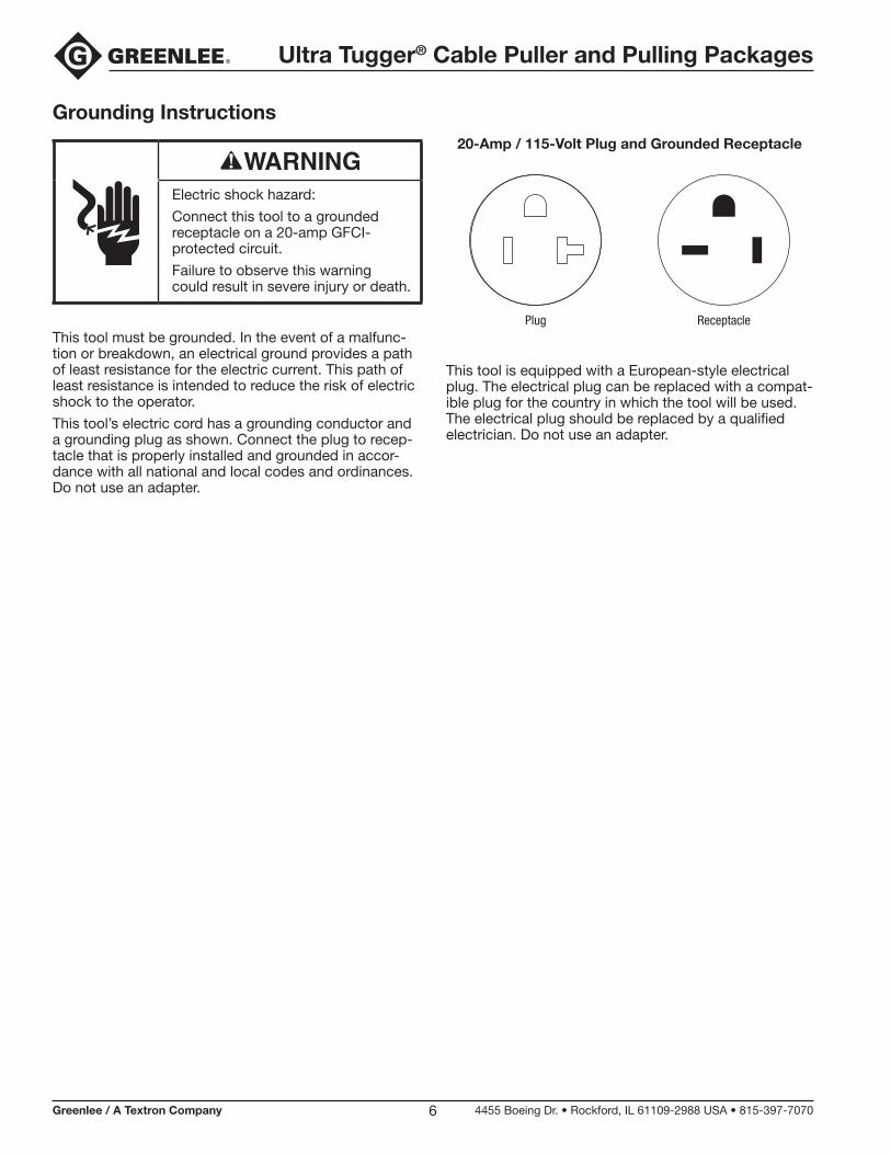
Electric shock hazard:
Connect this tool to a grounded receptacle on a 20-amp GFCI- protected circuit.
Failure to observe this warning could result in severe injury or death.
This tool must be grounded. In the event of a malfunc-tion or breakdown, an electrical ground provides a path of least resistance for the electric current. This path of least resistance is intended to reduce the risk of electric shock to the operator.
This tool’s electric cord has a grounding conductor and a grounding plug as shown. Connect the plug to recep-tacle that is properly installed and grounded in accor-dance with all national and local codes and ordinances. Do not use an adapter.
20-Amp / 115-Volt Plug and Grounded Receptacle
ReceptaclePlug
This tool is equipped with a European-style electrical plug. The electrical plug can be replaced with a compat-ible plug for the country in which the tool will be used. The electrical plug should be replaced by a qualified electrician. Do not use an adapter.

Ultra Tugger® Cable Puller and Pulling Packages
Greenlee / A Textron Company 4455 Boeing Dr. • Rockford, IL 61109-2988 USA • 815-397-70707
Identification
Ultra Tugger Cable Puller
1. Motor (under shroud)
2. Circuit Breaker / I/O Switch
3. Mounting Plates
4. Rope Tie-Off
5. Adjustable Sheave Bracket
6. Tapered Steel Capstan
7. Right Angle Sheave
8. Rope Ramp
9. Hitch Clip
10. Gearbox
11. Mounting Pin (2)
12. Force Gauge with Remote I/O Switch
1
2
3
45
6
7
9
11Lift Point
Lift Point
10
8
12
Ultra Tugger® Cable Puller and Pulling Packages
Greenlee / A Textron Company 4455 Boeing Dr. • Rockford, IL 61109-2988 USA • 815-397-70708
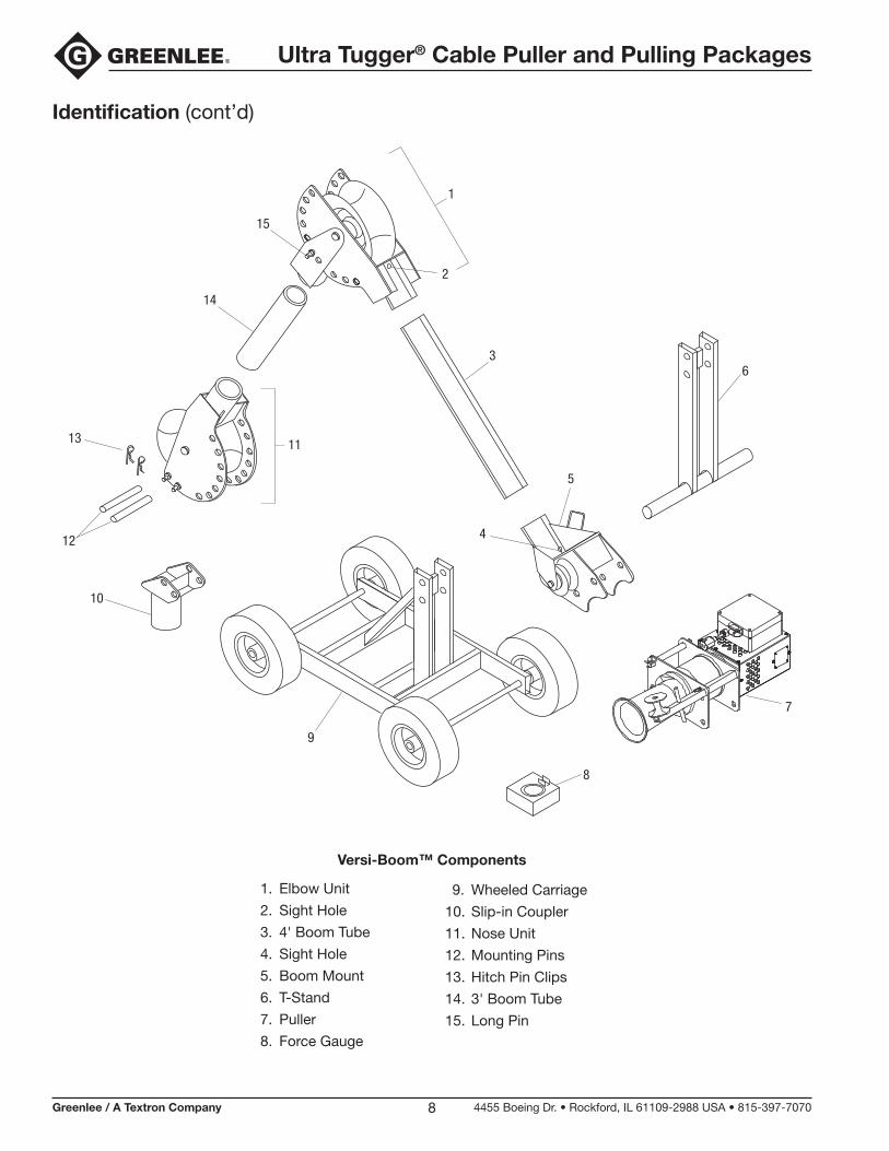
Identification (cont’d)
7
1
14
1113
12
10
2
3
5
9
6
4
15
8
1. Elbow Unit
2. Sight Hole
3. 4' Boom Tube
4. Sight Hole
5. Boom Mount
6. T-Stand
7. Puller
8. Force Gauge
Versi-Boom™ Components
9. Wheeled Carriage
10. Slip-in Coupler
11. Nose Unit
12. Mounting Pins
13. Hitch Pin Clips
14. 3' Boom Tube
15. Long Pin

Ultra Tugger® Cable Puller and Pulling Packages
Greenlee / A Textron Company 4455 Boeing Dr. • Rockford, IL 61109-2988 USA • 815-397-70709
Specifications
Weight ........................................................................................................ 43 kg (95 lb)
Dimensions
Length ................................................................................................. 29 cm (11.5")
Width .......................................................................................................68 cm (27")
Height .....................................................................................................25 cm (9.8")
Motor
Voltage ..................................................................115 VAC, 50/60 Hz, single phase
Current Draw at Full Load .................................................................................. 19 A
Sound Level ........................................................................................ Lwa 70 at 1 m
Power Source .................................................. 115 VAC, 50/60 Hz, 20 A, single phase
Speed
No Load.................................................................................... 2.74 m/min (9 ft/min)
8900 N (2000 lb) ....................................................................... 2.44 m/min (8 ft/min)
17.8 kN (4000 lb) ................................................................... 2.29 m/min (7.5 ft/min)
26.7 kN (6000 lb) ...................................................................... 2.13 m/min (7 ft/min)
35.6 kN (8000 lb) ...................................................................... 1.83 m/min (6 ft/min)
Pulling Force
0 kN to 17.8 kN (0 lb to 4000 lb) .............................................Continuous operation
17.8 kN to 35.6 kN (4000 lb to 8000 lb) ...................................... 5 minutes per hour
Pulling Rope
Required Rope ...................................................................22.2 mm (7/8") diameter, double-braided, polyester composite
Average Breaking Strength .......................................... 143 kN (32,000 lb) minimum
IP Rating
Motor .................................................................................................................. IP23
Ultra Tugger Cable Puller and Force Gauge Enclosure...................................... IP54
Temperature Rating
Transportation and Storage ................................ 55 °C to -25 °C (131 °F to -13 °F)
Elevation Rating .................................................... 1000 m (3280 ft) above sea level
Ultra Tugger® Cable Puller and Pulling Packages
Greenlee / A Textron Company 4455 Boeing Dr. • Rockford, IL 61109-2988 USA • 815-397-707010
Cable Pulling Glossaryanchoring system
any item or group of items that keeps a cable pulling component in place during the cable pull
capstan
the hollow cylinder of the cable puller that acts on the pulling rope to generate pulling force
coefficient of friction
the ratio that compares two amounts of force: (1) the force needed to move an object over a surface and (2) the force holding the object against the surface
This ratio is used to describe how the capstan and the rope work together.
connector
any item, such as a wire grip, clevis, swivel, or pulling grip, that connects the rope to the cable
direct line of pull
the areas next to the pulling rope and along its path; this includes the areas in front of, in back of, and under-neath the rope
maximum rated capacity
the amount of pulling tension that any component can safely withstand, rated in kilonewtons (metric) or pounds; the maximum rated capacity of every component must meet or exceed the maximum pulling force of the cable puller
Newton
a metric unit of force, equivalent to .225 pounds of force
pipe adapter sheave
attaches to conduit for pulling or feeding cable
pulling grip
connects the rope to the cable; consists of a wire mesh basket that slides over the cable and grips the insulation
pulling force
the amount of pulling tension developed by the cable puller, rated in newtons (metric) or pounds; a cable puller is usually described by the maximum pulling force that it can develop
resultant force
any force that is produced when two or more forces act on an object; applies to the sheaves of a cable pulling system
rope ramp
a device that works with a tapered capstan; guides the rope onto the capstan to prevent rope overlap
sheave
a pulley that changes the direction of the rope and cable
stored energy
the energy that accumulates in the pulling rope as it stretches, described in newton-meters (metric) or foot-pounds
support structure
any stationary object that a cable pulling system component is anchored to, such as a concrete floor (for the floor mount) or an I-beam (for a sheave)
tactile feedback
the way the rope feels as it feeds off of the capstan; the feel of the rope provides information about the progress of the pull to the operator
tail
the portion of the rope that the operator applies force to; this is the rope coming off of the capstan, and is not under the tension of the pull
tailing the rope
the operator’s main function; this is the process of applying force to the tail of the pulling rope—see the complete explanation under “Cable Pulling Principles.”
wire grip
connects the rope to the cable; some use a set screw to clamp onto the conductors of the cable
Ultra Tugger® Cable Puller and Pulling Packages
Greenlee / A Textron Company 4455 Boeing Dr. • Rockford, IL 61109-2988 USA • 815-397-707011
Cable Pulling Principles
Pulling cable is a complex process. This section of the manual describes and explains four main topics of pulling cable:
each cable pulling system component•
how these components work together•
forces that are generated •
procedures for the cable puller operator to follow•
While reading through this section of the manual, look for components that are shaded in the illustrations. The shading indicates components that are associated with the text.
Greenlee strongly recommends that each member of the cable pulling crew review this section of the manual before each cable pull.
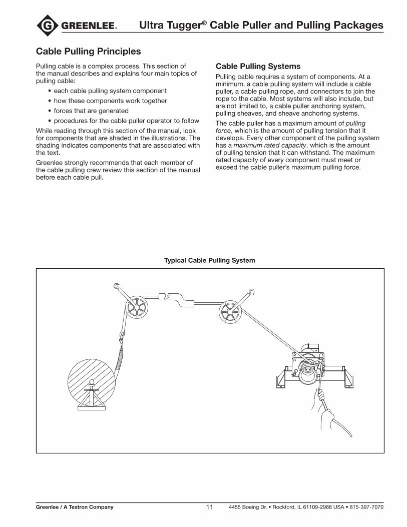
Cable Pulling SystemsPulling cable requires a system of components. At a minimum, a cable pulling system will include a cable puller, a cable pulling rope, and connectors to join the rope to the cable. Most systems will also include, but are not limited to, a cable puller anchoring system, pulling sheaves, and sheave anchoring systems.
The cable puller has a maximum amount of pulling force, which is the amount of pulling tension that it develops. Every other component of the pulling system has a maximum rated capacity, which is the amount of pulling tension that it can withstand. The maximum rated capacity of every component must meet or exceed the cable puller’s maximum pulling force.
Typical Cable Pulling System
Ultra Tugger® Cable Puller and Pulling Packages
Greenlee / A Textron Company 4455 Boeing Dr. • Rockford, IL 61109-2988 USA • 815-397-707012
Cable Pulling Principles (cont’d)
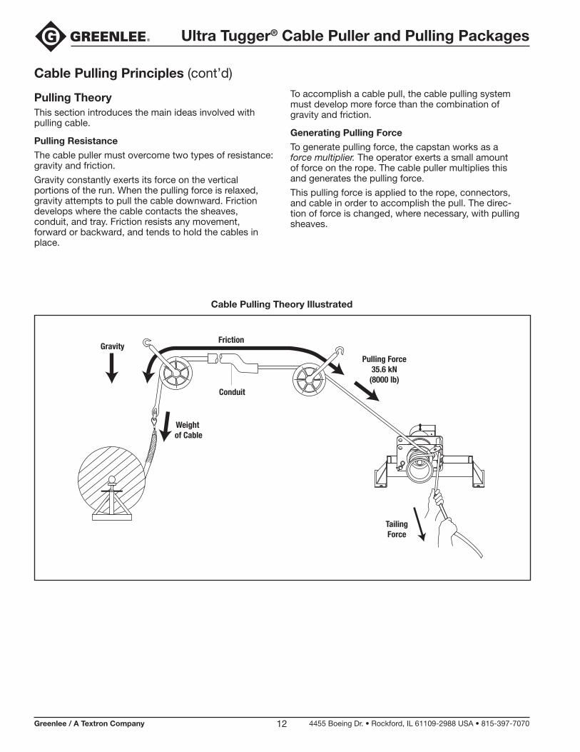
Pulling TheoryThis section introduces the main ideas involved with pulling cable.
Pulling Resistance
The cable puller must overcome two types of resistance: gravity and friction.
Gravity constantly exerts its force on the vertical portions of the run. When the pulling force is relaxed, gravity attempts to pull the cable downward. Friction develops where the cable contacts the sheaves, conduit, and tray. Friction resists any movement, forward or backward, and tends to hold the cables in place.
To accomplish a cable pull, the cable pulling system must develop more force than the combination of gravity and friction.
Generating Pulling Force
To generate pulling force, the capstan works as a force multiplier. The operator exerts a small amount of force on the rope. The cable puller multiplies this and generates the pulling force.
This pulling force is applied to the rope, connectors, and cable in order to accomplish the pull. The direc-tion of force is changed, where necessary, with pulling sheaves.
Cable Pulling Theory Illustrated
Gravity
Weight of Cable
Conduit
Friction
TailingForce
Pulling Force35.6 kN
(8000 lb)

Ultra Tugger® Cable Puller and Pulling Packages
Greenlee / A Textron Company 4455 Boeing Dr. • Rockford, IL 61109-2988 USA • 815-397-707013
Cable Pulling Principles (cont’d)
Cable Pulling Forces This section provides detailed explanations and illustra-tions of the forces that are generated during the cable pull. These explanations are based on the concepts presented in the last section, “Pulling Theory.”
At the Cable Puller Anchoring System
The cable puller will exert its maximum pulling force on cable puller’s anchoring system. It is extremely impor-tant the anchoring system can withstand this amount of force. Refer to “Setup: Floor Mount” for proper setup or installation.
Pulling Force at the Cable Puller’s Anchoring System
35.6 kN(8000 lb)Maximum35.6 kN
(8000 lb)Maximum
Pulling Force35.6 kN
(8000 lb)
Maximum Pulling Force at Anchoring System

Ultra Tugger® Cable Puller and Pulling Packages
Greenlee / A Textron Company 4455 Boeing Dr. • Rockford, IL 61109-2988 USA • 815-397-707014
Cable Pulling Principles (cont’d)
Cable Pulling Forces (cont’d)
At the Capstan
The capstan acts as a force multiplier. The operator exerts a small amount of tension, or tailing force, on the rope; the capstan multiplies this force to pull the cable. The resultant force depends upon the number of times the rope is wrapped around the capstan, as shown in the formula below.
Pulling Force = Tailing Force x e0.0175µø
Where: e = the natural logarithm, or 2.7183
µ = the coefficient of friction between the rope and the capstan *
ø = the number of degrees of wrap of rope around the capstan
* The average value for the coefficient of friction when double-braided composite rope is pulled over a clean dry capstan is 0.125.
The following table is based on the formula above. The input, or tailing force, is constant at 44.5 N (10 lb). Increasing the number of wraps increases the pulling force.
Operator’s Tailing Force
Number of Wraps of Rope
Approximate Pulling Force
44.5 N (10 lb)
1 93.4 N (21 lb)
2 213.5 N (48 lb)
3 474.9 N (106 lb)
4 1043.8 N (233 lb)
5 2293.7 N (512 lb)
6 5048.9 N (1127 lb)
7 11.1 kN (2478 lb)
This table shows how the capstan acts as a force multiplier. Because the coefficient of friction depends upon the condition of the rope and capstan, this formula cannot determine an exact amount of pulling force.
The Capstan as a Force Multiplier
Pulling Force: 35.6 kN (8000 lb)
TailingForce

Ultra Tugger® Cable Puller and Pulling Packages
Greenlee / A Textron Company 4455 Boeing Dr. • Rockford, IL 61109-2988 USA • 815-397-707015
Cable Pulling Principles (cont’d)
Stored Energy
Cable Pulling Forces (cont’d)
At the Pulling Rope
The product of a force (f) moving through a distance (d) is energy (f x d), and may be measured in newton-meters or foot-pounds. Energy is stored in a rope when the rope is stretched. This is similar to the way energy is stored in a rubber band when it is stretched. Failure of the rope or any other component of the pulling system can cause a sudden uncontrolled release of the energy stored in the rope.
For example, a 100-meter nylon rope with a 50,000 newton average breaking strength could stretch 40 meters and store 1,000,000 joules of energy. This is enough energy to throw a 900-kilogram object, such as a small automobile, 113 meters into the air.
A similar double-braided composite rope could store approximately 300,000 joules of energy. This could throw the same object only 34 meters into the air. The double-braided composite rope stores much less energy and has much less potential for injury if it were to break.
Double-braided composite rope is the only type of rope recommended for use with the Ultra Tugger cable puller. Select a double-braided composite rope with an average rated breaking strength of at least 143 kN (32,000 lb).
Stored Energy

Ultra Tugger® Cable Puller and Pulling Packages
Greenlee / A Textron Company 4455 Boeing Dr. • Rockford, IL 61109-2988 USA • 815-397-707016
Cable Pulling Principles (cont’d)
Cable Pulling Forces (cont’d)
At the Connectors
The connectors will be subjected to the cable puller’s maximum pulling force.
Several types of rope connectors—clevises, swivels, and rope-to-swivel connectors—are available. Follow the instructions provided with each to provide a good connection.
Two types of wire connectors—wire grips and pulling grips—are available. The wire grip uses a set screw to clamp onto the conductors of the cable. The pulling grip consists of a wire mesh basket that slides over the cable and grips the insulation.
A Typical Grip Setup—Clevis and Wire Grip
Maximum Pulling Force
35.6 kN(8000 lb)
A Typical Grip Setup—Swivel and Pulling Grip
Maximum Pulling Force
35.6 kN(8000 lb)
When selecting a pulling grip, it is extremely important to select a grip of the correct (1) type, (2) size, and (3) maximum rated capacity.
1. Select the correct type based on the descriptions of each type in the Greenlee catalog.
2. Measure the circumference of the wire bundle. (To do this accurately, fasten a tie strap around the bundle. Cut off and discard the tail. Then cut the tie strap and measure its length.) Use the table pro-vided to find the correct size.
3. See the maximum rated capacities in the Greenlee catalog.
Pulling Grip Size Table
Circumference Range Required Grip Diameter
inches mm inches mm
1.57–1.95 39.9–49.5 0.50–0.61 12.7–15.5
1.95–2.36 49.5–59.9 0.62–0.74 15.8–18.8
2.36–3.14 59.9–79.8 0.75–0.99 19.1–25.1
3.14–3.93 79.8–99.8 1.00–1.24 25.4–31.5
3.93–4.71 99.8–119.6 1.25–1.49 31.8–37.8
4.71–5.50 119.6–139.7 1.50–1.74 38.1–44.2
5.50–6.28 139.7–159.5 1.75–1.99 44.5–50.5
6.28–7.85 159.5–199.4 2.00–2.49 50.8–63.2
7.85–9.42 199.4–239.3 2.50–2.99 63.5–75.9
9.42–11.00 239.3–279.4 3.00–3.49 76.2–88.6
11.00–12.57 279.4–319.3 3.50–3.99 88.9–101.3
12.57–14.14 319.3–359.2 4.00–4.49 101.6–114.0
14.14–15.71 359.2–399.0 4.50–4.99 114.3–126.7
Ultra Tugger® Cable Puller and Pulling Packages
Greenlee / A Textron Company 4455 Boeing Dr. • Rockford, IL 61109-2988 USA • 815-397-707017
Cable Pulling Principles (cont’d)
Cable Pulling Forces (cont’d)
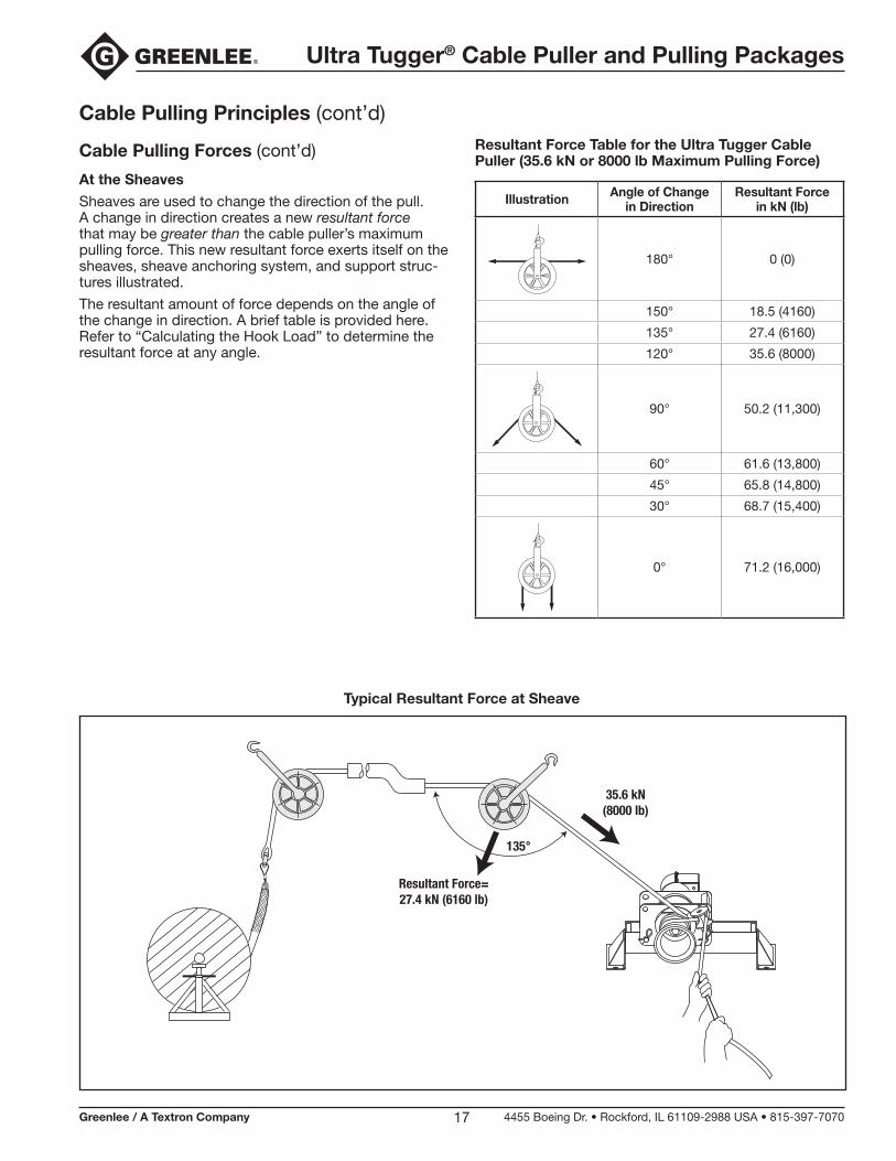
At the Sheaves
Sheaves are used to change the direction of the pull. A change in direction creates a new resultant force that may be greater than the cable puller’s maximum pulling force. This new resultant force exerts itself on the sheaves, sheave anchoring system, and support struc-tures illustrated.
The resultant amount of force depends on the angle of the change in direction. A brief table is provided here. Refer to “Calculating the Hook Load” to determine the resultant force at any angle.
Resultant Force Table for the Ultra Tugger Cable Puller (35.6 kN or 8000 lb Maximum Pulling Force)
Illustration Angle of Changein Direction
Resultant Forcein kN (lb)
180° 0 (0)
150° 18.5 (4160)
135° 27.4 (6160)
120° 35.6 (8000)
90° 50.2 (11,300)
60° 61.6 (13,800)
45° 65.8 (14,800)
30° 68.7 (15,400)
0° 71.2 (16,000)
Typical Resultant Force at Sheave
Resultant Force=27.4 kN (6160 lb)
35.6 kN(8000 lb)
135°

Ultra Tugger® Cable Puller and Pulling Packages
Greenlee / A Textron Company 4455 Boeing Dr. • Rockford, IL 61109-2988 USA • 815-397-707018
Cable Pulling Principles (cont’d)
Calculating the Hook Load
One Attachment Point
To calculate the hook load exerted at one attachment point, use the Reference Table and Formula 1.
Formula 1:
R = 2 x T x SIN ((180 - θ) / 2)
R = the resultant force, or hook load; this force is exerted on the hook, anchoring, and structural support
θ = the angle of change in rope direction
T = the tension exerted on the rope by the cable puller
Note: The total load on the support structure = R + the weight of the sheave.
Sheave with One Attachment Point
TT
R

Ultra Tugger® Cable Puller and Pulling Packages
Greenlee / A Textron Company 4455 Boeing Dr. • Rockford, IL 61109-2988 USA • 815-397-707019
Cable Pulling Principles (cont’d)
Calculating the Hook Load (cont’d)
Two Attachment Points
To calculate the hook loads exerted at two attachment points, use the Reference Table and Formulas 1, 2 and 3.
Formula 2: Formula 3:
R1 = ________________________ R2 = ________________________ COS A + SIN A / TAN B COS B + SIN B / TAN A
R1 = resultant force on left hook, anchoring, and support structure
R2 = resultant force on right hook, anchoring, and support structure
A = angle between the left mounting and the centerline of the two legs of the rope
B = angle between the right mounting and the centerline of the two legs of the rope
R = the resultant force, or hook load; this force is exerted on the hook, anchoring, and structural support
θ = the angle of change in rope direction
T = the tension exerted on the rope by the cable puller
Notes: The total load on the left support structure = R1 + the weight of the sheave.
The total load on the right support structure = R2 + the weight of the sheave.
T
R1
R2
T
R1R2
T
T
ANGLE B ANGLE BANGLE A
ANGLE
A
12 1
2
CL
CL
R R
Sheave with Two Attachment Points

Ultra Tugger® Cable Puller and Pulling Packages
Greenlee / A Textron Company 4455 Boeing Dr. • Rockford, IL 61109-2988 USA • 815-397-707020
Cable Pulling Principles (cont’d)
Calculating the Hook Load (cont’d)
Hook Load
Two variables interact with the sheave to produce a resultant (total) force, or hook load. This load, repre-sented by R in the formulas and illustrations, is exerted on the hook, anchoring, and structural support.
Sheave Forces
TT
R
R = the resultant force, or hook load; this force is exerted on the hook, anchoring, and structural support
θ = the angle of change in rope direction
T = the tension exerted on the rope by the cable puller
Reference Table
Illustration θ R
T T
R = 0
180° 0
150° .52 x T
135° .77 x T
120° 1 x T
T T
R = 1.41 x T
90° 1.41 x T
60° 1.73 x T
45° 1.85 x T
30° 1.93 x T
T T
R = 2 x T
0° 2 x T

Ultra Tugger® Cable Puller and Pulling Packages
Greenlee / A Textron Company 4455 Boeing Dr. • Rockford, IL 61109-2988 USA • 815-397-707021
Cable Pulling Principles (cont’d)
Some Hook Loads Illustrated
Hook Load = 1/2 of the Pulling Force Hook Load = 1-1/2 Times the Pulling Force
Hook Load Hook Load = Total Pulling Force
A straight rope exerts no load on the hook and structure. A rope that makes a 120° angle exerts the total pulling force on the hook and structure.
A rope that makes a 150° angle exerts 1/2 of the pulling force on the hook and structure.
A rope that makes a 90° angle exerts 1-1/2 times the pulling force on the hook and structure.
Hook Load = 2 Times the Pulling ForceHook Load = 3/4 of the Pulling Force
A rope that makes a 135° angle exerts 3/4 of the pulling force on the hook and structure.
A rope that makes a 0° angle exerts 2 times the pulling force on the hook and structure.
0
1
2
180° 120°
0
1
2
150°
0
1
2
90°
0
1
2
135°
0
1
2
0°
0
1
2

Ultra Tugger® Cable Puller and Pulling Packages
Greenlee / A Textron Company 4455 Boeing Dr. • Rockford, IL 61109-2988 USA • 815-397-707022
Cable Pulling Principles (cont’d)
Tailing the RopeThe rope must be pulled off of the capstan as the pull progresses. The rope that has left the capstan is the “tail.” The process of pulling the rope off of the capstan is called tailing the rope.
The resistance of the cable varies throughout the dura-tion of the cable pull. Changes in resistance are due to characteristics of the rope, changes in conduit direction, and changes in the amount of friction. The “feel” of the rope provides this information about the pull. This is called tactile feedback. Adjust the tailing force as neces-sary to compensate for these changes.
Control of the Pull
Decreasing the tailing force will decrease the pulling force, until the rope slips on the capstan and the pull stops. This provides a high level of control over the progress of the cable pull.
Do not allow the rope to slip on the capstan for more than a few moments. If it becomes necessary to com-pletely stop a pull, shut off the puller and maintain enough tailing force to hold cable in place. Tie the rope off to hold it in place. Use the rope tie-off to hold it in place.
Amount of Tailing Force
While the rope and cable are under tension, it is im-portant to maintain the proper amount of tailing force.
Too little tailing force will allow the rope to slip on the capstan. This will build up excessive heat and acceler-ate rope wear, increasing the possibility of breaking the rope.
The proper amount of tailing force will stop the rope from slipping on the capstan and produce a sufficient amount of pulling force to pull in the rope and cable.
Too much tailing force is any amount more than is nec-essary to stop the rope from slipping on the capstan. Excessive tailing force will not increase the pulling force or pulling speed.
Number of Wraps of Rope around the Capstan
An experienced operator should choose the number times the rope is wrapped around the capstan.
The proper number of wraps allows the operator to control the progress of the pull with a comfortable amount of effort.
Using too few wraps requires a large tailing force to accomplish the pull. Using too few wraps also makes the rope more likely to slip on the capstan. This builds up heat and accelerates rope wear.
Using too many wraps causes the rope to grab the capstan tighter. This accelerates rope wear, wastes power, and increases the possibility of a rope overlap. Using too many wraps also reduces tactile feedback, so you receive less information about the pull. You cannot quickly relax the tailing force when there are too many wraps.
If the rope becomes difficult to tail, add another wrap of rope. Turn off the puller and release all of the tension in the rope. Add a wrap and resume pulling. Be aware, however, that some pulls will require tension to hold the cables in place. In these cases, do not attempt to release all of the tension and add a wrap of rope. You will need to anticipate the number of wraps before start-ing the pull.
Preventing Rope Overlap
Do not allow the rope to become overlapped on the capstan during a pull.
A rope overlap will make it will impossible to continue or back out of the pull.
If the rope becomes overlapped, you will lose control of the pull —the rope will advance with no tailing force and will not feed off of the capstan. The capstan will not allow you to reverse the direction of the rope, so you cannot back out of an overlap.
Set up the puller properly. The rope ramp and tapered capstan are intended to prevent rope overlap. Refer to the instructions in the “Operation” section of this manual.
Every wrap of the rope must remain in direct contact with the capstan. During the pull, take great care to prevent the incoming rope from riding up and overlap-ping the next wrap. If an overlap begins to develop, immediately relax the tailing force on the rope so that the rope can feed back toward the conduit or tray. When the rope resumes its normal path, apply tailing force and continue the pull.
There is no suggested remedy for a rope overlap. Do not allow the rope to overlap!
Ultra Tugger® Cable Puller and Pulling Packages
Greenlee / A Textron Company 4455 Boeing Dr. • Rockford, IL 61109-2988 USA • 815-397-707023
Cable Pulling Principles (cont’d)
Summary of Cable Pulling PrinciplesA cable pulling system consists of many components • that work together to accomplish a pull.
The cable puller is rated by its maximum pulling force; • every other component is rated by its maximum rated capacity. The maximum rated capacity of every com-ponent must meet or exceed the maximum pulling force of the cable puller.
The cable puller must overcome two types of resis-• tance: gravity and friction. The puller’s capstan, the pulling rope, and the operator tailing the rope work together to produce pulling force.
The cable puller exerts force on every component • of the cable pulling system, including the anchoring systems and the support structures.
Energy is stored in a rope when the load causes • the rope to stretch. Failure of the rope or any other component can cause a sudden release of energy. Replace any rope that is worn or damaged.
Carefully select the number or wraps of rope around • the capstan before starting the pull.
Control the pull by tailing the rope. Be familiar with the • interaction of the rope and capstan.
Do not allow a rope overlap to develop.•
Planning the Pull
Pull in a direction that will require the lowest amount • of pulling force.
Plan several shorter pulls rather than fewer longer • pulls.
Locate the puller as close to the end of the conduit • as possible to minimize the amount of exposed rope under tension.
Place each component so that the pulling forces are • used effectively.
Select an anchoring system: adapter sheaves, which • are preferred, or the floor mount.
Verify that each component has the proper load • rating.
Inspect the structural supports. Verify that they have • enough strength to withstand the maximum forces that may be generated.
Make sure area is clear of bystanders, etc.•

Ultra Tugger® Cable Puller and Pulling Packages
Greenlee / A Textron Company 4455 Boeing Dr. • Rockford, IL 61109-2988 USA • 815-397-707024
Typical Setups
Setups are shown without force gauge. Place the force gauge so the operator has an unobstructed view of the meter and quick access to its I/O switch.
Chain Mount 00866 Secured to Steel Conduit or Pipe
Floor Mount 00865 Secured to a Concrete Floor

Ultra Tugger® Cable Puller and Pulling Packages
Greenlee / A Textron Company 4455 Boeing Dr. • Rockford, IL 61109-2988 USA • 815-397-707025
Typical Setups (cont’d)
Setups are shown without force gauge. Place the force gauge so the operator has an unobstructed view of the meter and quick access to its I/O switch.
T-Stand Pulling Horizontally Using One Boom Tube,
Nose Unit, and Slip-in Coupler
T-Stand Pulling Up Using One Boom Tube,
Nose Unit, and Slip-in Coupler
T-Stand Pulling Horizontally Using Two Boom Tubes, Nose Unit, Elbow Unit, and Slip-in Coupler
Ultra Tugger® Cable Puller and Pulling Packages
Greenlee / A Textron Company 4455 Boeing Dr. • Rockford, IL 61109-2988 USA • 815-397-707026
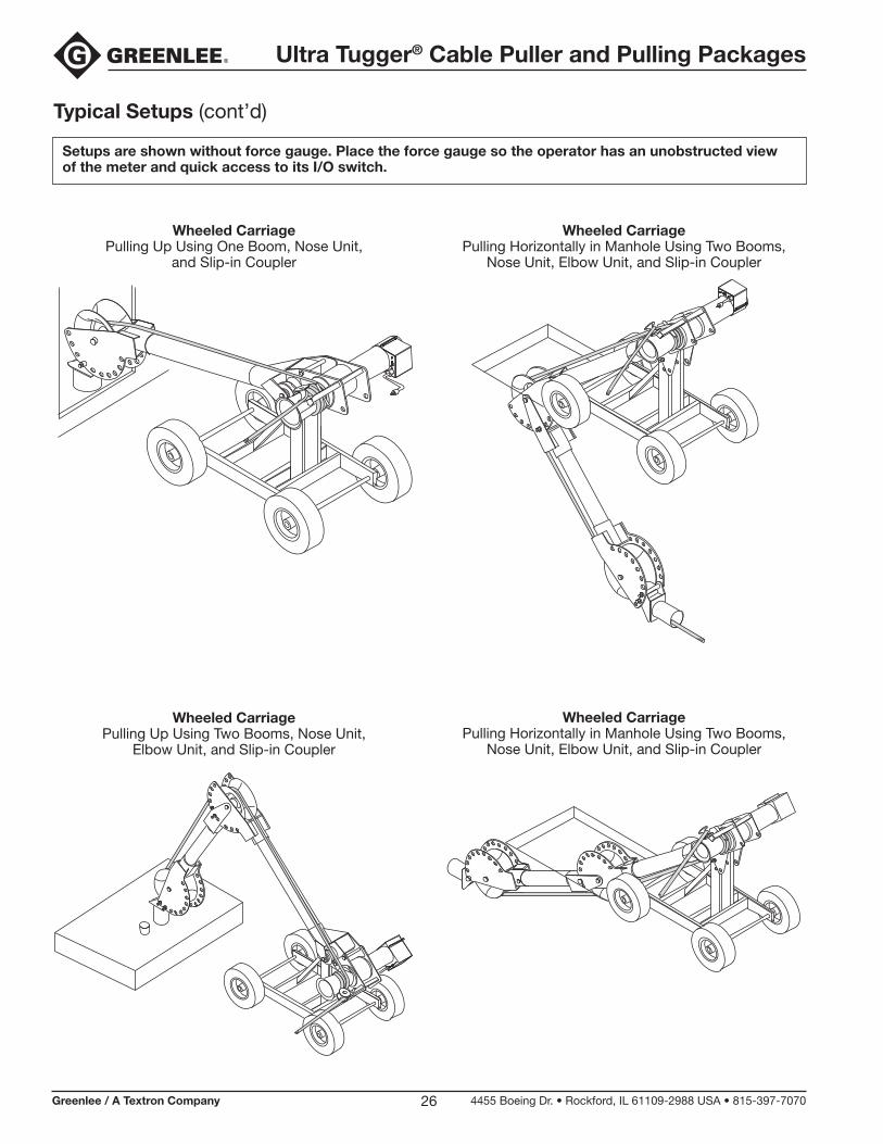
Typical Setups (cont’d)
Setups are shown without force gauge. Place the force gauge so the operator has an unobstructed view of the meter and quick access to its I/O switch.
Wheeled Carriage Pulling Up Using One Boom, Nose Unit,
and Slip-in Coupler
Wheeled Carriage Pulling Up Using Two Booms, Nose Unit,
Elbow Unit, and Slip-in Coupler
Wheeled Carriage Pulling Horizontally in Manhole Using Two Booms,
Nose Unit, Elbow Unit, and Slip-in Coupler
Wheeled Carriage Pulling Horizontally in Manhole Using Two Booms,
Nose Unit, Elbow Unit, and Slip-in Coupler
Ultra Tugger® Cable Puller and Pulling Packages
Greenlee / A Textron Company 4455 Boeing Dr. • Rockford, IL 61109-2988 USA • 815-397-707027
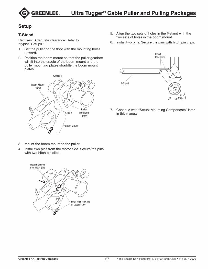
Setup
T-StandRequires: Adequate clearance. Refer to “Typical Setups.”
1. Set the puller on the floor with the mounting holes upward.
2. Position the boom mount so that the puller gearbox will fit into the cradle of the boom mount and the puller mounting plates straddle the boom mount plates.
Boom MountPlates
Boom Mount
Cradle
Gearbox
PullerMounting
Plates
3. Mount the boom mount to the puller.
4. Install two pins from the motor side. Secure the pins with two hitch pin clips.
Install Hitch Pin Clips on Capstan Side
Install Hitch Pins from Motor Side
5. Align the two sets of holes in the T-stand with the two sets of holes in the boom mount.
6. Install two pins. Secure the pins with hitch pin clips.
T-Stand
Insert Pins Here
7. Continue with “Setup: Mounting Components” later in this manual.

Ultra Tugger® Cable Puller and Pulling Packages
Greenlee / A Textron Company 4455 Boeing Dr. • Rockford, IL 61109-2988 USA • 815-397-707028
Setup (cont’d)
Wheeled CarriageRequires: Adequate clearance.Refer to “Typical Setups.”
1. Mount the boom mount to the wheeled carriage. Align the boom mount holes with the top holes in the wheeled carriage, as illustrated. Install a pin through the boom mount and wheeled carriage. Secure the pin with a hitch pin clip.
2. Position the puller’s gearbox above the boom mount cradle. Align the puller so that the puller mounting plates straddle the boom mount plates. Lower the puller onto the boom mount. Install two pins from the motor side. Secure the pins with two hitch pin clips.
3. Check the right angle sheave support tube to be sure it is fastened with the pin.
Removable Pin
4. Rotate the puller and boom mount as shown. When the second hole in the boom mount is aligned with the second hole in the wheeled carriage, install a pin. Secure the pin with a hitch pin clip.

Ultra Tugger® Cable Puller and Pulling Packages
Greenlee / A Textron Company 4455 Boeing Dr. • Rockford, IL 61109-2988 USA • 815-397-707029
Setup (cont’d)
Mounting Components
Boom with Nose Unit
3 m (10')MAXIMUM
Use only straight 3" diameter rigid steel conduit or • Schedule 40 steel pipe for the boom tubes.
Do not use boom tubes longer than 3 meters (10'). • Longer booms may bend or break.
Failure to observe this warning could result in severe injury or death.
STRAIGHT EDGESet up the elbow unit as shown. Improper setup will cause the elbow unit to collapse.
Failure to observe this warning could result in severe injury or death.
Use these boom tubes only:
boom tubes supplied with the cable puller•
3" rigid steel conduit (3 meters or 10 feet • maximum)
3" Schedule 40 pipe (3 meters or 10 feet • maximum)
1. Slide the boom tube into the boom mount until the tube bottoms out. Sight the tube through the sight hole to be sure the tube is fully inserted. Tighten the set screw.
2. Slide the nose unit onto the tube until the tube bottoms out. Sight the tube through the sight hole to be sure the tube is fully inserted. Tighten the set screw.
Sight Hole
Sight Hole

Ultra Tugger® Cable Puller and Pulling Packages
Greenlee / A Textron Company 4455 Boeing Dr. • Rockford, IL 61109-2988 USA • 815-397-707030
Setup (cont’d)
Mounting Components (cont’d)
Booms with Elbow Unit and Nose Unit
3 m (10')MAXIMUM
Use only straight 3" diameter rigid steel conduit or • Schedule 40 steel pipe for the boom tubes.
Do not use boom tubes longer than 3 meters (10'). • Longer booms may bend or break.
Failure to observe this warning can result in severe injury or death.
STRAIGHT EDGESet up the elbow unit as shown. Improper setup will cause the elbow unit to collapse.
Failure to observe this warning could result in severe injury or death.
Use these boom tubes only:
boom tubes supplied with the cable puller•
3" rigid steel conduit (3 meters or 10 feet • maximum)
3" Schedule 40 pipe (3 meters or 10 feet • maximum)
1. Slide the boom tube into the boom mount until the tube bottoms out. Sight the tube through the sight hole to be sure the tube is fully inserted. Tighten the set screw.
2. Slide the elbow unit onto the tube until the tube bottoms out. Sight the tube through the sight hole to be sure the tube is fully inserted. Tighten the set screw.
3. Adjust the elbow to an appropriate angle and lock it in place with a pin. Secure the pin with a hitch pin clip.
4. Slide the boom tube into the elbow unit until the tube bottoms out. Sight the tube through the sight hole to be sure the tube is fully inserted. Tighten the set screw.
5. Slide the nose unit onto the tube until the tube bottoms out. Sight the tube through the sight hole to be sure the tube is fully inserted. Tighten the set screw.
Sight Hole
Sight Hole
Sight Hole

Ultra Tugger® Cable Puller and Pulling Packages
Greenlee / A Textron Company 4455 Boeing Dr. • Rockford, IL 61109-2988 USA • 815-397-707031
Setup (cont’d)
Mounting Components (cont’d)
Slip-in Coupler
Requires: One pin to connect to nose unit
1. Select the coupler that best fits the conduit.
2. Slide the coupler into the conduit until the coupler seats on the end of the conduit.
Note: If the coupler doesn’t seat on the conduit, refer to “Straddling the Conduit with a Slip-In Coupler.”
PullConduit
Coupler
Coupler must seat on the Conduit here
3. Slide the nose unit over the coupler. Align any set of holes and insert one pin. Secure the pin with a hitch pin clip.
Note: If possible, add a second pin and hitch pin clip.
Nose Unit
Coupler
Pin secured with Hitch Pin Clip
Straddling the Conduit with Slip-in Coupler
Requires: Two pins to connect to nose unit
1. Select a coupler at least 25 mm (1") larger than the conduit.
2. Place the coupler over the conduit.
Note: Do not use this method if the coupler does not seat on a support structure that can support 35.6 kN (8000 lb) of force.
PullConduit
Coupler
Conduit must not protrudepast here
SupportStructure
3. Slide the nose unit over the coupler. Align any two sets of holes and insert two pins. Secure the pins with hitch pin clips.
Pull Conduit
Coupler
Conduit must not protrude past here
SupportStructure

Ultra Tugger® Cable Puller and Pulling Packages
Greenlee / A Textron Company 4455 Boeing Dr. • Rockford, IL 61109-2988 USA • 815-397-707032
Setup (cont’d)
Chain MountRequires: Exposed metallic conduit with the following characteristics:
63.5 mm to 254 mm (2-1/2" to 10") in diameter•
capable of withstanding at least 35.6 kN (8000 lb) of • force
Do not mount the pipe adapter to the following:
steel conduit less than 63.5 mm • (2-1/2") in diameter
PVC conduit of any size.•
These conduits will not support the loads imposed by the puller.
Failure to observe this warning could result in severe injury or death.
NO
NO
When setting up the pipe adapter, do not use the vise chains on a structural support that is less than 51 mm (2") or more than 254 mm (10") wide. An oversized or under-sized structural support can allow the puller to slide or break loose and strike nearby personnel.
Failure to observe this warning could result in severe injury or death.
Install the vise chains properly.
Follow the vise chain tightening instructions care-• fully. Improperly tightened chains can allow the puller to slide or break loose and strike nearby personnel.
Do not allow the vise chains to bind at the corners • when mounting the puller to a square or rectangu-lar support. The vise chain must be uniformly tight at all points.
Failure to observe this warning could result in severe injury or death.
Do not pull between the 10 o’clock and 2 o’clock directions. Pulling between 10 o’clock and 2 o’clock can damage the mounting conduit.
12O’CLOCK
1
2
3
11
10
9
6O’CLOCK
PULLINGROPE
PULLLOAD
TAILINGROPE
VISE CHAINS
SUPPORT

Ultra Tugger® Cable Puller and Pulling Packages
Greenlee / A Textron Company 4455 Boeing Dr. • Rockford, IL 61109-2988 USA • 815-397-707033
Setup (cont’d)
Chain Mount (cont’d)1. On each vise chain unit:
a. Rotate the vise chain handle counterclockwise to expose most of the threads. Leave only three or four threads engaged in the handle.
b. Wrap the chain around the conduit.
c. Pull the vise chain tight and insert the chain pins into the chain pockets, or recesses.
d. Turn the handle clockwise to slightly tighten the chain.
2. Set the puller into the cradle of the chain mount.
3. Install two pins from the motor side. Secure the pins with two hitch pin clips.
Install Pins from
Motor Side

Ultra Tugger® Cable Puller and Pulling Packages
Greenlee / A Textron Company 4455 Boeing Dr. • Rockford, IL 61109-2988 USA • 815-397-707034
Setup (cont’d)
Floor MountRequires: A concrete floor with the following characteristics:
fully cured structural-type concrete•
minimum compressive strength of 211 kg/cm• 2 (3000 psi)
free of cracks, crumbling, or patchwork•
Follow all floor mounting instructions carefully.
An improperly attached floor mount can come • loose and strike nearby personnel.
Do not attach the floor mount to masonry, brick, • or cinder block. These materials will not hold the anchors securely.
Failure to observe this warning could result in severe injury or death.
1. Determine the best position for locating the floor mount. Locate the floor mount:
on a flat section•
at least 152 mm (6") from edge of concrete•
as close to the conduit as possible to reduce the • amount of exposed rope under tension
so that the pull rope will approach the puller’s • capstan at a 90° (±5°) angle.
at least 152 mm (6")
at least 152 mm (6")
at least 152 mm (6")
90°
2. Set the floor mount in the desired location. Use the floor mount as a template to drill four ∅15.87 mm (5/8") holes at least 152 mm (6") deep.
Note: Use a ∅15.87 mm (5/8") carbide-tipped masonry bit manufactured in accordance with ANSI standard B94.12-77.
3. Vacuum the debris from the holes.
Installation
Greenlee recommends using Greenlee 35607 Wedge Anchors. If another type of anchor is used, they must have an ICBO (International Conference of Building Officials) allowable tension and shear rating of 10.7 kN (2400 lb) in 211 kg/cm2 (3000 psi) concrete.
1. Assemble the nut and washer to the anchor so the top of the nut is flush with the top of the anchor, as shown.
Top ofAnchor
Nut
Washer
2. Insert the four anchors through the floor mount and into the holes in the floor.
3. Hammer the anchors in until the washer is in firm contact with the floor mount.
4. Expand the anchors by torquing the nuts to 122 to 128 Nm (90 to 95 ft-lb).
If any of the four anchors spin before the minimum torque is achieved, abandon the location and start elsewhere. An improperly installed anchor can allow the puller to break loose.
Failure to observe this warning could result in severe injury or death.
5. Have the installation checked by a qualified inspector.

Ultra Tugger® Cable Puller and Pulling Packages
Greenlee / A Textron Company 4455 Boeing Dr. • Rockford, IL 61109-2988 USA • 815-397-707035
Operation
1. Fish the rope through the conduit.
2. Set up the cable puller. Refer to “Typical Setups” illustrations and instructions in this manual.
Set up the cable puller so that the rope will approach the capstan at an angle of 90° (±5°). Angles outside of this range may cause the rope to overlap.
90° (±5°)
3. Set the rope ramp as follows:
a. Wind the rope several times around the capstan.
b. Pull the ramp away from the mounting plate and rotate it until the flat surface contacts the rope.
c. Push the ramp toward the mounting plate and rotate it counterclockwise until it locks into place.
4. Check the I/O switch on the puller to be sure it is OFF (O). Plug the puller into the receptacle of the standard force gauge.
5. Connect the force gauge to an appropriate power supply (refer to “Grounding Instructions” in this manual).
Note: If using an extension cord, it must be rated for 20 amps. Use the shortest cord possible. Longer cords reduce puller speed.
6. Position the force gauge so that it can be monitored by the puller operator.
Duty Cycle Table
Color Band on Meter
Pounds of Pulling Force
Duty Cycle (in minutes)
Green 0–17.8 kN (0–4000 lb) continuous
Yellow 17.8–35.6 kN (4000–8000 lb) 5 per hour
Red over 35.6 kN (8000 lb) puller will stop
7. Turn the circuit breaker in the force gauge ON (I).
8. Grasp the tailing end of the rope. Apply a slight amount of tailing force.
9. Turn the puller ON (I).
10. Tail the rope, allowing the spent rope to accumulate on the floor between the operator and the puller.
11. When the pull is complete, turn the puller OFF (O). Tie off the rope and anchor the cable.
Entanglement hazard:
Do not wrap rope around hands, arms, waist, or other body parts. Do not stand in spent coils or tailed rope. Hold rope so that it may be released quickly.
Failure to observe this warning could result in severe injury or death.
Ultra Tugger® Cable Puller and Pulling Packages
Removing Cable
Removing old cable involves the same principles as installing new cable. However, there are some important differences.
Pulling ForceIt is difficult to predict the amount of pulling force necessary to remove an old cable. The cable may be damaged, and it may break with an unexpectedly low pulling force.
The required pulling forces may be very high:
The cable has probably “taken a set.” Unlike the new • cable on a reel, cable in conduit has probably been in the conduit for years, or perhaps decades. The cable will resist bending and straightening as it is pulled through the conduit.
The pulling lubricant has probably hardened, • increasing pulling resistance.
The insulation may be damaged and the cable may be • corroded.
Dirt or other foreign matter may have entered the • conduit and may have cemented the cable in place.
Using a Force GaugeWhen pulling old cable out of a conduit, the pulling force will be highest when starting the pull. Select a cable puller and pulling components to meet or exceed the estimated amount of pulling force necessary to remove the old cable. Because breaking the cable free will require the largest amount of pulling force, it is neces-sary to use a force gauge to prevent overloading the system components. Use the 07120 Force Gauge Unit.
Carefully monitor the pulling force at the force gauge; if the puller is not able to begin the pull, shut off the puller and disassemble the setup. Start over with a puller and components of a higher force rating.
Puller PlacementPulling out old cable is generally accomplished with the puller located some distance away from the end of the conduit. This allows the pulling crew to pull out a long section of cable before turning off the puller, cutting off the cable, and reattaching the grip(s). Mounting the cable puller a distance away from the end of the conduit increases the amount of exposed rope, which greatly increases the amount of violent whipping action which would occur if the rope were to break.
To isolate the operator from the rope path:
Locate the puller so that you will stand behind an • obstruction, such as a wall. Set up the puller so that you will be able to maintain control of the pull. You need a clear view of the rope as it feeds onto the capstan, including several feet of the rope in front of the capstan. You must be able to turn off the puller before the pulling grip, connector, or swivel contacts the capstan.
Use an additional pulling sheave to change the direc-• tion of the tailing rope. Anchor the sheave so that you are close enough to maintain control of the pull. You need a clear view of the rope as it feeds onto the capstan, including several feet of the rope in front of the capstan. You must be able to turn off the puller before the pulling grip, connector, or swivel contacts the capstan.
Note: Use the additional pulling sheave to change the direction of the tailing rope (after the rope leaves the capstan). Do not change the direction of the pulling rope.
Use a longer tailing rope than usual and stand away • from the puller. Stand as far from the puller as pos-sible, while maintaining control of the pull. You need a clear view of the rope as it feeds onto the capstan, including several feet of the rope in front of the capstan. You must be able to turn off the puller before the pulling grip, connector, or swivel contacts the capstan.
USA 800-435-0786 Fax: 800-451-2632 815-397-7070 Fax: 815-397-1865Canada 800-435-0786 Fax: 800-524-2853International +1-815-397-7070 Fax: +1-815-397-9247
4455 Boeing Drive • Rockford, IL 61109-2988 • USA • 815-397-7070An ISO 9001 Company • Greenlee Textron Inc. is a subsidiary of Textron Inc.
www.greenlee.com