instruction manual (remote control/english)
TRANSCRIPT

NF Corporation
DIGITAL LOCK-IN AMPLIFIER
LI 5645 / LI 5650
INSTRUCTION MANUAL(REMOTE CONTROL)


DIGITAL LOCK-IN AMPLIFIER
LI 5645 / LI 5650
INSTRUCTION MANUAL(REMOTE CONTROL)
DA00054241-002

Trademarks
National Instruments are registered trademarks of National Instruments Corporation in the
United States.
Other company names and product names used in this instruction manual may be trademarks or
registered trademarks of their respective companies.

i LI 5645 / LI 5650
Preface
This instruction manual explains procedures remotely controlling the LI 5645 / LI 5650.
■ The LI 5645 / LI 5650 are provided with the following instruction manuals.
LI 5645 / LI 5650 Instruction Manual (Operations)
Explains procedures for operating the LI 5645 / LI 5650 from the panel, maintaining it, and
other basic information.
LI 5645 / LI 5650 Instruction Manual (Remote Control)
This instruction manual explains procedures for using the LI 5645 / LI 5650 by remote
control.
LI 5645 / LI 5650 Instruction Manual (Remote Control) is included on the provided CD-ROM.
A sample program for controlling the LI 5645 / LI 5650 is included on the provided CD-ROM. Also
included are representative programming languages, and examples of combinations of the GPIB, USB,
RS-232, and LAN interfaces. For details, see the instructions provided with the included CD-ROM.
Preface
ii LI 5645 / LI 5650
■ This instruction manual has the following chapter organization.
1.Preparation Before Use
Explains interface settings and precautions.
2.Switching between remote / local states
Explains how to switch between remote operation and local operation.
3.Responses to interface messages
Shows responses to principle IEEE-488.1 interface messages.
4.Command list and command tree
Provides outlines of all commands.
5.Command explanation
Explains details of individual commands.
6.Status system
Explains the status system.
7.Trigger system
Outlines the trigger system.
8.Data acquisition using the measurement data buffers
Provides procedures for measurement sing the measurement data buffer.
9.Error Messages
Explains error messages related to remote control.
10.Embedded Web Site
Explains the embedded web site.

iii LI 5645 / LI 5650
Table of Contents
Page 1. Preparation Before Use ····················································································· 1
1.1 Remote control interface selection ................................................................................ 2 1.2 USB outline .................................................................................................................... 3
1.2.1 Controller preparation ............................................................................................................. 3 1.2.2 LI 5645 / LI 5650 preparation ................................................................................................... 4 1.2.3 Identification of USB devices .................................................................................................. 4
1.3 RS-232 outline ............................................................................................................... 6 1.3.1 Controller preparation ............................................................................................................. 6 1.3.2 LI 5645 / LI 5650 preparation ................................................................................................... 6 1.3.3 Connection .............................................................................................................................. 9 1.3.4 Limitations and precautions .................................................................................................. 10
1.4 GPIB outline ................................................................................................................ 11 1.4.1 Controller preparation ........................................................................................................... 11 1.4.2 LI 5645 / LI 5650 preparation ................................................................................................. 11 1.4.3 Precautions regarding GPIB use ........................................................................................... 12 1.4.4 Basic GPIB specifications ..................................................................................................... 12
1.5 LAN outline .................................................................................................................. 13 1.5.1 Controller preparation ........................................................................................................... 13 1.5.2 LI 5645 / LI 5650 preparation ................................................................................................. 13 1.5.3 Connection ............................................................................................................................ 18 1.5.4 Limitations and precautions .................................................................................................. 18 1.5.5 Embedded web site............................................................................................................... 18
1.6 Precautions regarding communication ........................................................................ 19
2. Switching between remote / local states ······························································· 21
3. Responses to interface messages ······································································ 23
4. Command list and command tree········································································ 25
5. Command explanation ······················································································ 35
5.1 Language outline ......................................................................................................... 36 5.1.1 Subsystem commands .......................................................................................................... 36 5.1.2 Path separator ...................................................................................................................... 36 5.1.3 Abbreviation of keywords ...................................................................................................... 37 5.1.4 Optional keywords ................................................................................................................ 37
5.2 Sequential commands ................................................................................................. 37 5.3 Detailed command explanations ................................................................................. 38
5.3.1 Common commands ............................................................................................................. 40 5.3.2 Subsystem commands .......................................................................................................... 44
6. Status system ································································································· 99
6.1 Status system outline ................................................................................................. 100 6.2 Status Byte ................................................................................................................ 101 6.3 Standard Event status ............................................................................................... 102 6.4 Operation status ........................................................................................................ 104 6.5 Questionable Status .................................................................................................. 107
7. Trigger system ······························································································ 111
8. Data acquisition using the measurement data buffers ··········································· 115
9. Error Messages ···························································································· 119
10. Embedded Web Site ····················································································· 123
10.1 Preparation .............................................................................................................. 124 10.2 Requirements .......................................................................................................... 124 10.3 How to access web pages ....................................................................................... 124

Table of Contents
iv LI 5645 / LI 5650
10.4 About web pages ..................................................................................................... 125 10.4.1 Navigation Menu ............................................................................................................... 125 10.4.2 Descriptions of Menu ........................................................................................................ 125 10.4.3 Welcome Page .................................................................................................................. 126 10.4.4 Remote Control ................................................................................................................. 127 10.4.5 Logging ............................................................................................................................. 128 10.4.6 LAN Configuration ............................................................................................................. 129 10.4.7 Security ............................................................................................................................. 131 10.4.8 Update .............................................................................................................................. 131 10.4.9 Glossary ............................................................................................................................ 131

Table of Contents
v LI 5645 / LI 5650
Figures and Tables
Page
Fig. 1-1 RS-232 connection cable wiring diagram ·························································· 9
Fig. 6-1 Status system ·························································································· 100
Fig. 6-2 Standard Event status structure ··································································· 102
Fig. 6-3 Operation Status structure ·········································································· 104
Fig. 6-4 Questionable Status structure ····································································· 107
Fig. 7-1 Trigger system ························································································· 112
Fig. 10-1 Navigation Menu ····················································································· 125
Fig. 10-2 Identification dialogue ·············································································· 126
Fig. 10-3 Control Panel ························································································· 127
Fig. 10-4 Logging ································································································ 128
Fig. 10-5 Authentication Dialogue ··········································································· 131
Table 3-1 Responses to interface messages ····························································· 24
Table 4-1 Common command list ············································································ 26
Table 4-2 Subsystem command list ········································································· 27
Table 6-1 Status Byte register definition ···································································· 101
Table 6-2 Content of the Standard Event Status register. ·············································· 102
Table 6-3 Operation Condition register, Event register content ······································ 105
Table 6-4 Operation Transition Filter and Event register transition ·································· 106
Table 6-5 Questionable Condition register, Event register content ·································· 108
Table 6-6 Questionable Transition Filter and Event register transition ····························· 109
Table 9-1 Error messages ····················································································· 120
Table 10-1 Menu Icons ························································································· 125
Table 10-2 List of Parameters at Welcome Page ························································ 126
Table 10-3 List of the Buttons at Logging Page ·························································· 128
Table 10-4 List of the Parameters at LAN Configuration ··············································· 129

Table of Contents
vi LI 5645 / LI 5650

1 LI 5645 / LI 5650
1. Preparation Before Use

1.Preparation Before Use
2 LI 5645 / LI 5650
The LI 5645 / LI 5650 can be used for remote control by USB, RS-232, GPIB, or LAN.
By sending program messages and receiving response messages pertaining to measurement values and
settings, the controller provides control identical to panel operation.
The interface connectors are located on the back panel of the LI 5645 / LI 5650.
1.1 Remote control interface selection
The LI 5645 / LI 5650 remote control interface is used by selecting one of the USB, RS-232, GPIB, and
LAN interfaces. Multiple interfaces cannot be used simultaneously.
■ {Utility screen}
First press the _ _UTIL key to display the utility screen.
[ INTERFACE] _ _SCRN__ / EXIT _ _UTIL_
[ INTERFACE] Switches to the {interface configuration screen}.
In this instruction manual, square brackets ([ ]) are used to indicate soft keys during panel
operation, or to show keyword that can be omitted when sending commands.
■ {Interface configuration screen}
Main settings of selected interface Remote:GPIB, Address 2
[USB>] Selects USB and switches to the {USB information screen}.
[GPIB>] Selects GPIB and switches to the {GPIB configuration screen}.
[RS232>] Selects RS-232 and switches to the {RS-232 configuration screen}.
[LAN>] Selects LAN and switches to the {LAN configuration screen}.
_SCRN_ / EXIT Returns display to the {Other operation screen}. (Returns to the utility
screen)

1.Preparation Before Use
3 LI 5645 / LI 5650
1.2 USB outline
1.2.1 Controller preparation
When using the USB interface, make sure that the controller (controlling computer) is equipped with a
USB interface.
Install the USBTMC driver on the controller. Ordinarily, this driver supports the USB488 subclass, and
makes practically the same control provided by GPIB with USB.
USBTMC: Universal Serial Bus Test and Measurement Class
This driver is included in all hardware and software products of companies that provide the VISA
library. Users who do not have a VISA library license will need to obtain one separately.
VISA: Virtual Instrument Software Architecture
Examples of companies that provide the VISA library (no particular order, information current as of
creation of this document)
National Instruments Corporation
Keysight Technologies, Inc.
Tektronix, Inc.
Using the VISA library, operation can be unified with any of USB, RS-232, GPIB, LAN to the extent of
the supports.
1.Preparation Before Use
4 LI 5645 / LI 5650
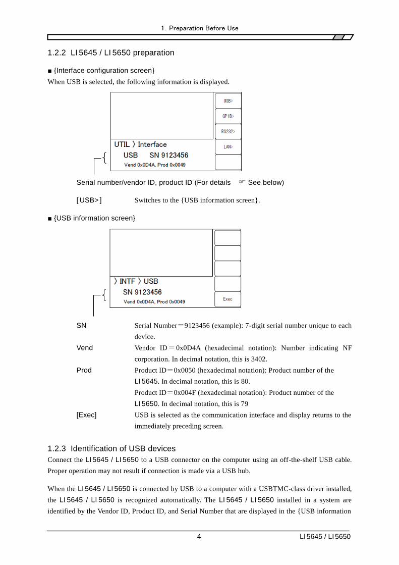
1.2.2 LI 5645 / LI 5650 preparation
■ {Interface configuration screen}
When USB is selected, the following information is displayed.
Serial number/vendor ID, product ID (For details See below)
[ USB> ] Switches to the {USB information screen}.
■ {USB information screen}
SN Serial Number=9123456 (example): 7-digit serial number unique to each
device.
Vend Vendor ID=0x0D4A (hexadecimal notation): Number indicating NF
corporation. In decimal notation, this is 3402.
Prod Product ID=0x0050 (hexadecimal notation): Product number of the
LI 5645. In decimal notation, this is 80.
Product ID=0x004F (hexadecimal notation): Product number of the
LI 5650. In decimal notation, this is 79
[Exec] USB is selected as the communication interface and display returns to the
immediately preceding screen.
1.2.3 Identification of USB devices
Connect the LI 5645 / LI 5650 to a USB connector on the computer using an off-the-shelf USB cable.
Proper operation may not result if connection is made via a USB hub.
When the LI 5645 / LI 5650 is connected by USB to a computer with a USBTMC-class driver installed,
the LI 5645 / LI 5650 is recognized automatically. The LI 5645 / LI 5650 installed in a system are
identified by the Vendor ID, Product ID, and Serial Number that are displayed in the {USB information

1.Preparation Before Use
5 LI 5645 / LI 5650
screen}. If the device is not recognized automatically, recognition can be achieved by entering these
values directly.

1.Preparation Before Use
6 LI 5645 / LI 5650
1.3 RS-232 outline
1.3.1 Controller preparation
When using the RS-232 interface, make sure that the controller (controlling computer) is equipped with
a serial communication (RS-232) connector.
Make the same settings for the following parameters on both the LI 5645 / LI 5650 and the controller.
・ Communication speed 4800 to 230400 bps
・ Data length 8 bits (*1)
・ Stop bit length 1 during transmission, 1 during reception (*1)
・ Parity None (*1)
・ Flow control None / Software / Hardware
・ Terminator LF / CR LF
*1: Fixed on the LI 5645 / LI 5650. Cannot be altered.
1.3.2 LI 5645 / LI 5650 preparation
■ {Interface configuration screen}
When RS-232 is selected, the following information is displayed.
Current settings: Data rate/flow control, terminator
[RS232>] Switches to the {RS-232 configuration screen}.
■ {RS-232 configuration screen}
Current settings: Data rate/selectable range
[ BAUD RATE ] Switches to the {Baud rate configuration screen}.

1.Preparation Before Use
7 LI 5645 / LI 5650
[ FLOW CONTROL ]
Switches to the {Flow control configuration screen}.
[ TERMINATOR ] Switches to the {Terminator configuration screen}.
[Exec] Saves settings and returns display to the {Interface configuration screen}
RS-232 is selected as the communication interface.
__SCRN__ / EXIT Returns display to the {Interface configuration screen}.
■ {Baud rate configuration screen}
Sets the baud rate (communication speed). The baud rate is the same for both transmission and
reception.
Current settings / Selectable range
Selection from among the following is possible using the up/down keys or
the modify knob.
4800, 9600, 19200, 38400, 57600, 115200, 230400 bps
[ BAUD RATE ], [ FLOW CONTROL ], [ TERMINATOR ]
These switch display to the respective configuration screens.
At communication speeds greater than 19200 bps, a short and low-capacitance cable must be used.
■ {Flow control configuration screen}
Configures flow control.
Current settings / Selectable range
Selection from among the following is possible using the up/down keys or
the modify knob.
NONE No flow control (the default setting)
SOFT Software flow control

1.Preparation Before Use
8 LI 5645 / LI 5650
Communication is managed using control codes (X-ON and X-OFF).
Reliable communication can be achieved using a connection cable with
just TxD, RxD, and GND lines. However, transfer of binary data is not
possible. Further, effective communication speed may be reduced. In
hexadecimal notation, X-ON is 11, and X-OFF is 13.
HARD Hardware flow control
Communication is managed using hardware flow control (RTS and CTS).
[ BAUD RATE ], [ FLOW CONTROL ], [ TERMINATOR ]
These switch display to the respective configuration screens.
When flow control is enabled, transmission is suspended when the receive buffer approaches
capacity, then restarts when the receive buffer opens up.
■ {Terminator configuration screen}
A message terminator is required at the end of each set of commands or responses to signify
termination.
Current settings / Selectable range
Selection from among the following is possible using the up/down keys or
the modify knob.
LF Configures the terminator as a single LF (Line Feed) character.
CRLF Configures the terminator as the 2 characters CR (Carriage Return) and
LF. In hexadecimal notation, CR is 0x0D and LF is 0x0A.
[ BAUD RATE ], [ FLOW CONTROL ], [ TERMINATOR ]
These switch display to the respective configuration screens.
・During LI 5645 / LI 5650 transmission,
the selected terminator is added to the end of response messages.
・During LI 5645 / LI 5650 reception,
When the terminator that has been set for the LI 5645 / LI 5650 is received, the command is
executed.
After completing configuration, save the settings with [Exec] to select RS-232 as the communication
interface and return display to the {Interface configuration screen}.

1.Preparation Before Use
9 LI 5645 / LI 5650
1.3.3 Connection
For connection, use an off-the-shelf connection cable, which must be purchased separately. When
making connection to a serial interface on a personal computer, use the following type of cable.
Cable specifications: D-Sub, 9-pin, female-female, interlink cable using inch-standard screw.
In order to avoid misoperation due to radiation and interference resulting from
electromagnetic noise, be sure to use a shielded cable.
Communication can be established if at least the three lines RxD, TxD, and GND are connected.
The RTS and CTS lines are required in order to use hardware flow control.
An interlink cable is required in order to use hardware flow control (Fig. 1-1(b)). Some cables have
cross or reversed lines in which pins 7 and 8 are connected together (Fig. 1-1(c)). Communication is
also possible with this type of cable, but hardware flow control is not possible.
(a) Rear panel RS-232 connector
LI 5645 / LI 5650 Personal computer
(PC/AT, etc.)
Signal name
Pin no. Pin no. Signal name
— 1 1 — 1 1
RxD 2 2 RxD 2 2
TxD 3 3 TxD 3 3
DTR 4 4 DTR 4 4
GND 5 5 GND 5 5
— 6 6 — 6 6
RTS 7 7 RTS 7 7
CTS 8 8 CTS 8 8
— 9 9 — 9 9
Frame Frame
(b) Interlink connection (c) Other cross connections
Fig. 1-1 RS-232 connection cable wiring diagram
Inch screw
(#4-40)

1.Preparation Before Use
10 LI 5645 / LI 5650
1.3.4 Limitations and precautions
• RS-232 only allows the controller to be connected in a 1-to-1 configuration.
It is not possible to connect multiple devices in parallel to a single port.
• Functions such as SRQ and Device Clear that are unique to GPIB cannot be used.
The BREAK signal or Control-C (0x03 in hexadecimal notation) can be used as an alternate to the
Device Clear function. However, Control-C cannot be used during binary transfer.
The :SYSTem{:LOCal|:REMote|:RWLock} command can largely substitute for the remote local
function. The :SYSTem:KLOCk can be used to lock operation from the panel.
• Clear the receive buffer before starting communication.
If device power is turned on or off, or the RS-232 cable is connected or disconnected while the
controller has the RS-232 communication path open, abnormal data may enter the controller's
receive buffer. Therefore, before starting normal operation, the program on the controller should
clear the controller's receive buffer (e.g., by initializing communication) upon starting or restarting
communication.
In the same way, abnormal data can be left in the receive buffer of the LI 5645 / LI 5650. Clear the
receive buffer using the BREAK signal or other equivalent of Device Clear.

1.Preparation Before Use
11 LI 5645 / LI 5650
1.4 GPIB outline
This interface is provided for use in environments that are well-suited to use of GPIB. It should not be
used in environments that are exposed to high levels of electromagnetic noise.
1.4.1 Controller preparation
Install an off-the-shelf GPIB interface card in the controller (the controlling computer) and connect the
LI 5645 / LI 5650 using a GPIB cable. See the manual included with the GPIB interface regarding
GPIB driver software.
1.4.2 LI 5645 / LI 5650 preparation
With GPIB, devices included in the system are identified by device-specific addresses. Set different
GPIB addresses for each device.
■ {Interface configuration screen}
When GPIB is selected, the following information is displayed.
Current setting: GPIB address
[ GPIB> ] Switches to the {GPIB configuration screen}.
■ {GPIB configuration screen}
Only the address can be set.
Current settings / Settable range
Select the GPIB address using the up/down keys or the modify knob.
[Exec] Saves the configuration, sets the communication interface to GPIB, and
returns display to the {Interface configuration screen}.

1.Preparation Before Use
12 LI 5645 / LI 5650
■ Message terminator
A terminator is required at the end of each set of commands or responses to signify termination.
The response message terminator sent by the LI 5645 / LI 5650 is fixed to LF^EOI.
Any of the following can be used as program message terminators that are received by the LI 5645 /
LI 5650.
・ LF Line Feed code
・ LF^EOI EOI (END message) accompanying LF
・ (Last code)^EOI EOI (End message) appended to the last code
1.4.3 Precautions regarding GPIB use
・ Before connecting or disconnecting the GPIB connector, turn off power to all devices connected
to the bus.
・ When using GPIB, turn on power to all divices connected to the bus.
・ With GPIB, the maximum number of devices that can be connected to the same bus is 15,
including the controller.
Further, length of the cable is subject to the following restrictions.
- Total cable length ≦ (2 m×number of devices or 20m, whichever is shorter)
- Length of any single cable ≦ 4 m
・ Set different GPIB addresses for each device. Output collisions arising when multiple devices
with the same address are connected to the same bus can result in device damage.
1.4.4 Basic GPIB specifications
■ GPIB conforming standards
IEEE std 488.1-1987, IEEE std 488.2-1992
■ IEEE std 488.1-1987 interface functions
SH1 Complete send flow source handshake function
AH1 Complete receive accepter handshake function
T6 Basic Talker, Serial Pole, and talker cancel function by listener-addressed privided
No Talk-Only function
L4 Basic Listener function, function to cancel the listener by talker-addressed provided
No Listen-Only function
SR1 Complete Service Request function
RL1 Complete Remote-Local function
PP0 No Parallel Poll function
DC1 Complete Device Clear function
DT1 Complete Device Trigger function
C0 No Controller function
E1 Open collector drive

1.Preparation Before Use
13 LI 5645 / LI 5650
1.5 LAN outline
1.5.1 Controller preparation
When using the LAN interface, make sure that the controller (controlling computer) is equipped with a
LAN interface. The LI 5645 / LI 5650 supports communication using TCP/IP protocol.
1.5.2 LI 5645 / LI 5650 preparation
■ {Interface configuration screen}
When LAN is selected, the following information is displayed.
Current main settings: IP address / port number / MAC Address
[ LAN> ] Switches to the {LAN configuration screen}.
■ {LAN configuration screen}
Current statuses: LAN status / IP address / IP configuration method (manual or auto)
STBY Indicates any other interface has selected or waiting for LAN interface to
start.
NFLT Indicates the LAN interface is ready and possible to communicate.
FLT Indicates the LAN interface is not possible to communicate.
The following are the reasons :
- Network cable is disconneced.
- Failure to obtain an IP address via DHCP server.
1.Preparation Before Use
14 LI 5645 / LI 5650
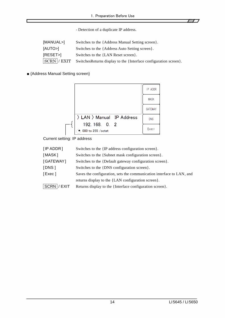
- Detection of a duplicate IP address.
[MANUAL>] Switches to the {Address Manual Setting screen}.
[AUTO>] Switches to the {Address Auto Setting screen}.
[RESET>] Switches to the {LAN Reset screen}.
_SCRN_ / EXIT SwitchesReturns display to the {Interface configuration screen}.
■ {Address Manual Setting screen}
Current setting: IP address
[ IP ADDR ] Switches to the {IP address configuration screen}.
[ MASK ] Switches to the {Subnet mask configuration screen}.
[ GATEWAY ] Switches to the {Default gateway configuration screen}.
[ DNS ] Switches to the {DNS configuration screen}.
[ Exec ] Saves the configuration, sets the communication interface to LAN, and
returns display to the {LAN configuration screen}.
_SCRN_ / EXIT Returns display to the {Interface configuration screen}.

1.Preparation Before Use
15 LI 5645 / LI 5650
■ {IP address configuration screen}
Current settings / settable range
Set individual octets (8 bits) as decimal numbers.
Use the cursor keys or modifier knob.
[ IP ADDR ], [ MASK ], [ GATEWAY ], [ DNS ]
These switches display to the respective configuration screens.
Set the address (logical address) that identifies the device which under the Internet Protocol (IP).
Addresses in the range 192.168.0.0 to 192.168.255.255 are private IP addresses available for free
assignment in small-scale local networks (Class C).
■ {Subnet mask configuration screen}
Current settings / settable range
Set individual octets (8 bits) as decimal numbers.
[ IP ADDR ], [ MASK ], [ GATEWAY ], [ DNS ]
These switches display to the respective configuration screens.
Set a mask that separates upper IP network addresses from lower IP host addresses

1.Preparation Before Use
16 LI 5645 / LI 5650
■ {Default gateway configuration screen}
Current settings / settable range
Set individual octets (8 bits) as decimal numbers.
[ IP ADDR ], [ MASK ], [ GATEWAY ], [ DNS ]
These switches display to the respective configuration screens.
Set the IP address of the gateway to be used implicitly when accessing an external network.
■ {DNS configuraion screen}
Current settings / settable range
Set individual octets (8 bits) as decimal numbers.
[ IP ADDR ], [ MASK ], [ GATEWAY ], [ DNS ]
These switches display to the respective configuration screens.
Set the IP address of the DNS (Domain Name Server) to be used to resolve a host name to an IP
address.
After completing configuration, save the settings with [Exec] to select LAN as the communication
interface and return display to the {Interface configuration screen}.

1.Preparation Before Use
17 LI 5645 / LI 5650
■ {Address Auto Setting screen} (Firmware version 1.50 or later)
[ Exec ] Saves the configuration, sets the communication interface to LAN, and
returns display to the {LAN configuration screen}.
_SCRN_ / EXIT Returns display to the {Interface configuration screen}.
When the IP auto configuration is selected and executed, this device request to obtain an IP
adrerss to a DHPC server. If the device objtains a valid IP address from a DHCP server, it is
possible to communicate.
However, If the device does not obtain a valid IP address, the device will assign a link-local
address that is defined in the address block 169.254.0.0/16 by using APIPA (Automatic
Private IP Addressing).
■ {LAN Reset screen} (Firmware version 1.50 or later)
[ Exec ] Resets LAN settings and returns display to the {LAN configuration
screen}. If the LAN setting reset is completed, the device start
communication with the IP auto configuration.
[ Cancel ] Cancels resetting LAN settings and returns display to the {LAN
configuration screen}.
_SCRN_ / EXIT Returns display to the {LAN configuration screen}.
1.Preparation Before Use
18 LI 5645 / LI 5650
1.5.3 Connection
Use a straight cable when connecting the LI 5645 / LI 5650 to the network.
When connecting directly to a personal computer, use a cross cable.
However, if the device connected automatically discriminates between straight and cross connection,
either type of cable may be used.
1.5.4 Limitations and precautions
• Functions such as SRQ and Device Clear that are unique to GPIB cannot be used.
Control-C (03H in hexadecimal notation) can be used as an alternate to the Device Clear function.
However, Control-C cannot be used during binary transfer.
The :SYSTem{:LOCal|:REMote|:RWLock} command can substitute for the Remote Local
function.
1.5.5 Embedded web site
When the firmware version 1.50 or later and the LAN interface is enabled, you can access the built-in
web site. Please refer to Chapter “10.Embedded Web Site” for details on the web site.

1.Preparation Before Use
19 LI 5645 / LI 5650
1.6 Precautions regarding communication
■ Input buffer
・ Commands received are placed in a buffer and interpreted and executed in the order received
The size of the input buffer is 100K bytes (1K=1024). Program messages exceeding this size are
interpreted and executed in the order received.
・ If an disallowed command is discovered during interpretation, an error occurs upon execution and
subsequent commands are not executed until the program message terminator is received.
■ Output buffer
・ The capacity of the output buffer is 100K bytes (1K=1024).
・ If the maximum capacity is exceeded, the output buffer is cleared and the Standard Event Status
register's query error bit is set to 1. Interpretation and execution of subsequent commands may
continue as normal, but all response messages generated are discarded until the program message
terminator is reached.
・ A separate 4M bytes of memory is provided for use as measurement data buffer.
■ Error queue
・ The maximum number of error messages that can be queued is 16.
・ If this number is exceeded, the 16th message changes to "Queue overflow" to indicate that the
error queue has overflowed. Subsequent error messages are discarded. The 15 error messages
already in the queue are maintained.
■ Program message terminator
When sending commands from the controller, append LF (Line Feed, 0x0A hex) to the end of the
output character string as the program message terminator. Further, append EOI (End message) as the
last byte. Some devices may not operate properly unless LF and EOI are appended to commands sent.
Depending on the driver software used as the control computer, unless program message terminators
are specified together with commands themselves, program message terminators may not be output.
Although NL (New Line) is sometimes indicated instead of LF (Line Feed), the binary code is the
same.
Since the concept of END messages do not apply in case of RS-232 and LAN, EOI is not appended.
■ Restrictions applicable to RS-232 and LAN
Functions that are unique to GPIB cannot be used. Examples are shown below.
Reception of Device Clear (DCL, SDC) messages
Reception of GTL (Go To Local) messages
Reception of LLO (Local Lockout) messages
Reception of GET (Group Execute Trigger) messages
Reception of REN (Remote Enable) messages
Transmission of SRQ (Service Request) messages
Serial Poll (reception of SPE / SPD and transmission of status bytes)
Transmission of END message (the EOI signal as message terminator)

1.Preparation Before Use
20 LI 5645 / LI 5650

21 LI 5645 / LI 5650
2. Switching between remote / local states

2.Switching between remote / local states
22 LI 5645 / LI 5650
In regard to remote control, the LI 5645 / LI 5650 has a remote states and a local state.
In the local state, all panel operations are possible.
In the remote state, all panel operations are disabled except for the TRIG key and the operation that
returns operation to the local state.
■ Switching to the remote state
Ordinarily, the remote state is used during operation through GPIB. This depends on driver
functionality on the controller side. Under the communication standard, specifying a device as the
listener when the REN message is TRUE puts that device in the remote state. The same applies to
operation with USB (USBTMC).
■ Switching to the local state
Operation can be returned to the local state from the remote state by pressing the _CLR_ / LOCAL
key on the front panel (except during Local Lockout).
Operation can be returned to the local state from the controller by sending the GTL command or
returning the REN line to FALSE. Since disconnecting the GPIB cable makes the REN line FALSE,
operation returns to the local state.
■ Prohibiting local operation from the panel
Accidental local operation can be prevented by specifying Local Lockout from the controller, During
Local Lockout, operation cannot be returned to the local state by pressing the _ _CLR_ / LOCAL key.
From the controller, operation to return to the local state is possible from the controller even during
Local Lockout.
■ Remote/local operation with RS-232 and LAN
When a command is sent to the LI 5645 / LI 5650, the LI 5645 / LI 5650 returns to the remote state.
When the local state is restored by pressing the _CLR_ / LOCAL key, panel operation is enabled.
The following commands can be used with RS-232 or LAN.
:SYSTem:LOCal (switches to the local state)
:SYSTem:REMote (switches operation to the remote state)
:SYSTem:RWLock (switches to the remote state with Local Lockout)
REMOTE lamp
In the remote state, the REMOTE lamp lights, and in the Local Lockout state, it flashes (at a slow rate).
After the power is turned on, remote control cannot be used while the REMOTE lamp is flashing
(at a high rate).
__CLR__ / LOCAL key REMOTE lamp

23 LI 5645 / LI 5650
3. Responses to interface messages

3.Responses to interface messages
24 LI 5645 / LI 5650
The principle IEEE-488.1 interface messages are as follows.
Table 3-1 Responses to interface messages
Message Function
IFC < InterFace Clear >
Initializes the GPIB interface.
Releases the specified listener and talker.
DCL, SDC < Device CLear >, < Selected Device Clear >
Clears the input buffer and cancels command interpretation / execution.
Clears the output buffer and clears bit 4 (MAV) of the Status Byte register.
LLO < Local Lockout >
Prohibits switching from the remote state to the local state by pressing the _
_CLR_ / LOCAL key.
GTL < Go To Local >
Switches to the local state.
GET < Group Execute Trigger >
Executes a trigger. Works the same as the *TRG command.
The procedure for sending interface messages from the controller varies according to device driver. For
details, see the relevant driver manual.
These functions cannot be used with RS-232 and LAN. However, alternate functions are provided for
some of them.

25 LI 5645 / LI 5650
4. Command list and command tree

4.Command list and command tree
26 LI 5645 / LI 5650
The LI 5645 / LI 5650 commands can broadly be grouped into common commands as defined in
IEEE488.2, and subsystem commands corresponding to device-specific functions.
Common commands supported by the LI 5645 / LI 5650 are listed in Table 4-1.
The LI 5645 / LI 5650 subsystem commands are listed in Table 4-2.
Symbols used in Tables 4-1 and 4-2 have the following meanings.
・ Square brackets ([ ]) indicate optional keywords.
・ A vertical bar ( | ) indicates that you should select one keyword from among a set of keywords.
・ Lowercase characters in keywords indicates that those characters are optional.
Table 4-1 Common command list
Com- mand
Name Function
*CLS Clear Status Command Clears the status.
*ESE *ESE?
Standard Event Status
Enable Command / Query
Sets/queries the Standard Event Status Enable register.
*ESR? Standard Event Status
Register Query
Queries the Standard Event Status register.
*IDN? Identification Query Queries the device identification information (such as model
name).
*OPC *OPC?
Operation Complete
Command / Query
Specifies that the OPC bit of the Standard Event Status
register be set to 1 when all command processing has been
completed. When all processing has been completed, 1 is
returned in response to a query.
*RCL Recall Command Restores the contents of the specified configuration memory.
*RST Reset Command Resets the device and restores settings to default values.
*SAV Save Command Saves current settings to the specified configuration memory.
*SRE *SRE?
Service Request Enable
Command / Query
Sets and queries the Service Request Enable register.
*STB? Read Status Byte Query Queries the status byte.
*TRG Trigger Command While awaiting a trigger when the trigger source is BUS,
measurement data is recorded in the measurement data buffer
when a trigger event occurs.
*TST? Self-Test Query Always returns 0.
*WAI Wait-to-Continue
Command
Postpones execution of ensuing commands until execution of
all commands has been completed.
4.Command list and command tree
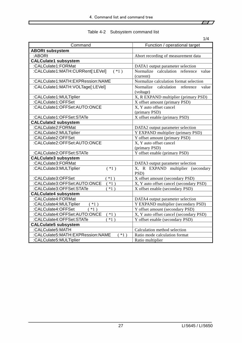
27 LI 5645 / LI 5650
Table 4-2 Subsystem command list
1/4
Command Function / operational target
ABORt subsystem
:ABORt Abort recording of measurement data
CALCulate1 subsystem
:CALCulate1:FORMat DATA1 output parameter selection
:CALCulate1:MATH:CURRent[:LEVel] ( *1 ) Normalize calculation reference value
(current)
:CALCulate1:MATH:EXPRession:NAME Normalize calculation format selection
:CALCulate1:MATH:VOLTage[:LEVel] Normalize calculation reference value
(voltage)
:CALCulate1:MULTiplier X, R EXPAND multiplier (primary PSD)
:CALCulate1:OFFSet X offset amount (primary PSD)
:CALCulate1:OFFSet:AUTO:ONCE X, Y auto offset cancel
(primary PSD)
:CALCulate1:OFFSet:STATe X offset enable (primary PSD)
CALCulate2 subsystem
:CALCulate2:FORMat DATA2 output parameter selection
:CALCulate2:MULTiplier Y EXPAND multiplier (primary PSD)
:CALCulate2:OFFSet Y offset amount (primary PSD)
:CALCulate2:OFFSet:AUTO:ONCE X, Y auto offset cancel
(primary PSD)
:CALCulate2:OFFSet:STATe Y offset enable (primary PSD)
CALCulate3 subsystem
:CALCulate3:FORMat DATA3 output parameter selection
:CALCulate3:MULTiplier ( *1 ) X, R EXPAND multiplier (secondary
PSD)
:CALCulate3:OFFSet ( *1 ) X offset amount (secondary PSD)
:CALCulate3:OFFSet:AUTO:ONCE ( *1 ) X, Y auto offset cancel (secondary PSD)
:CALCulate3:OFFSet:STATe ( *1 ) X offset enable (secondary PSD)
CALCulate4 subsystem
:CALCulate4:FORMat DATA4 output parameter selection
:CALCulate4:MULTiplier ( *1 ) Y EXPAND multiplier (secondary PSD)
:CALCulate4:OFFSet ( *1 ) Y offset amount (secondary PSD)
:CALCulate4:OFFSet:AUTO:ONCE ( *1 ) X, Y auto offset cancel (secondary PSD)
:CALCulate4:OFFSet:STATe ( *1 ) Y offset enable (secondary PSD)
CALCulate5 subsystem
:CALCulate5:MATH Calculation method selection
:CALCulate5:MATH:EXPRession:NAME ( *1 ) Ratio mode calculation format
:CALCulate5:MULTiplier Ratio multiplier
4.Command list and command tree
28 LI 5645 / LI 5650
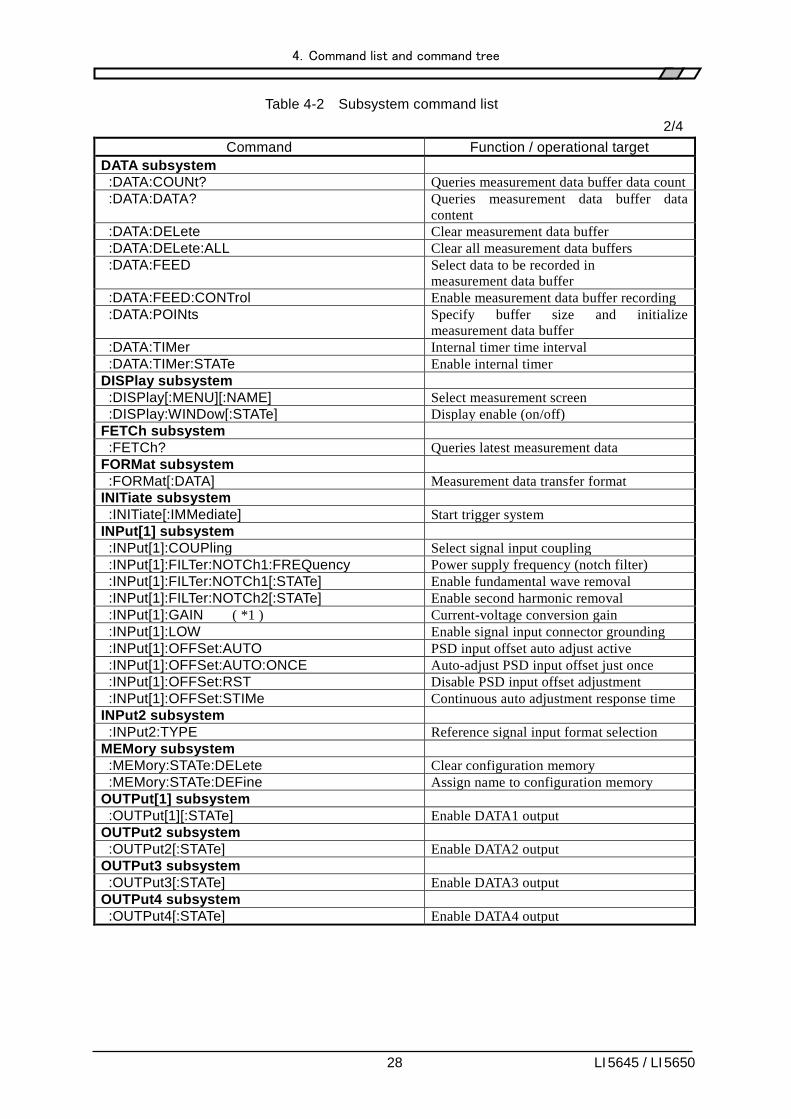
Table 4-2 Subsystem command list
2/4
Command Function / operational target
DATA subsystem
:DATA:COUNt? Queries measurement data buffer data count
:DATA:DATA? Queries measurement data buffer data
content
:DATA:DELete Clear measurement data buffer
:DATA:DELete:ALL Clear all measurement data buffers
:DATA:FEED Select data to be recorded in
measurement data buffer
:DATA:FEED:CONTrol Enable measurement data buffer recording
:DATA:POINts Specify buffer size and initialize
measurement data buffer
:DATA:TIMer Internal timer time interval
:DATA:TIMer:STATe Enable internal timer
DISPlay subsystem
:DISPlay[:MENU][:NAME] Select measurement screen
:DISPlay:WINDow[:STATe] Display enable (on/off)
FETCh subsystem
:FETCh? Queries latest measurement data
FORMat subsystem
:FORMat[:DATA] Measurement data transfer format
INITiate subsystem
:INITiate[:IMMediate] Start trigger system
INPut[1] subsystem
:INPut[1]:COUPling Select signal input coupling
:INPut[1]:FILTer:NOTCh1:FREQuency Power supply frequency (notch filter)
:INPut[1]:FILTer:NOTCh1[:STATe] Enable fundamental wave removal
:INPut[1]:FILTer:NOTCh2[:STATe] Enable second harmonic removal
:INPut[1]:GAIN ( *1 ) Current-voltage conversion gain
:INPut[1]:LOW Enable signal input connector grounding
:INPut[1]:OFFSet:AUTO PSD input offset auto adjust active
:INPut[1]:OFFSet:AUTO:ONCE Auto-adjust PSD input offset just once
:INPut[1]:OFFSet:RST Disable PSD input offset adjustment
:INPut[1]:OFFSet:STIMe Continuous auto adjustment response time
INPut2 subsystem
:INPut2:TYPE Reference signal input format selection
MEMory subsystem
:MEMory:STATe:DELete Clear configuration memory
:MEMory:STATe:DEFine Assign name to configuration memory
OUTPut[1] subsystem
:OUTPut[1][:STATe] Enable DATA1 output
OUTPut2 subsystem
:OUTPut2[:STATe] Enable DATA2 output
OUTPut3 subsystem
:OUTPut3[:STATe] Enable DATA3 output
OUTPut4 subsystem
:OUTPut4[:STATe] Enable DATA4 output

4.Command list and command tree
29 LI 5645 / LI 5650
Table 4-2 Subsystem command list
3/4
Command Function / operational target
ROUTe[1] subsystem
:ROUTe[1][:TERMinals] Signal input connector selection
ROUTe2 subsystem
:ROUTe2[:TERMinals] Reference source selection
SENSe subsystem
[:SENSe]:AUTO:ONCE Automatic setting
[:SENSe]:CURRent[1]:AC:RANGe:AUTO ( *1 ) Auto current sensitivity setting
[:SENSe]:CURRent[1]:AC:RANGe:AUTO:ONCE ( *1 )
Auto-set current sensitivity just once.
[:SENSe]:CURRent[1]:AC:RANGe[:UPPer] ( *1 ) Current sensitivity (primary PSD)
[:SENSe]:CURRent2:AC:RANGe[:UPPer] ( *1 ) Current sensitivity (secondary PSD)
[:SENSe]:DATA Measurement data (set) selection
[:SENSe]:DETector[:FUNCtion] ( *1 ) Detection mode
[:SENSe]:DREServe Dynamic reserve
[:SENSe]:FILTer[1][:LPASs]:AUTO:ONCE Automatic time constant setting
[:SENSe]:FILTer[1][:LPASs]:SLOPe Attenuation slope (primary PSD)
[:SENSe]:FILTer[1][:LPASs]:TCONstant Filter Time constant (primary PSD)
[:SENSe]:FILTer[1][:LPASs]:TYPE Filter type (primary PSD)
[:SENSe]:FILTer2[:LPASs]:SLOPe ( *1 ) Attenuation slope (secondary PSD)
[:SENSe]:FILTer2[:LPASs]:TCONstant ( *1 ) Filter Time constant (secondary PSD)
[:SENSe]:FILTer2[:LPASs]:TYPE ( *1 ) Filter type (secondary PSD)
[:SENSe]:FREQuency[1]? Frequency (fundamental wave, primary
frequency)
[:SENSe]:FREQuency[1]:HARMonics Harmonic measurement enable (primary
PSD)
[:SENSe]:FREQuency[1]:MULTiplier Harmonic order (primary PSD)
[:SENSe]:FREQuency[1]:SMULtiplier Subharmonic order (primary PSD)
[:SENSe]:FREQuency2? ( *1 ) Secondary frequency
[:SENSe]:FREQuency2:HARMonics ( *1 ) Harmonic measurement enable (secondary
PSD)
[:SENSe]:FREQuency2:MULTiplier ( *1 ) Harmonic order (secondary PSD)
[:SENSe]:NOISe[:SMOothing][:APERture] Noise smoothing factor
[:SENSe]:PHASe[1] Reference signal phase shift (primary PSD)
[:SENSe]:PHASe[1]:AUTO:ONCE Auto phase adjustment (primary PSD)
[:SENSe]:PHASe2 ( *1 ) Reference signal phase shift (secondary
PSD)
[:SENSe]:PHASe2:AUTO:ONCE ( *1 ) Auto phase adjustment (secondary PSD)
[:SENSe]:ROSCillator:SOURce? Standard clock selection
[:SENSe]:VOLTage[1]:AC:RANGe:AUTO Auto voltage sensitivity setting
[:SENSe]:VOLTage[1]:AC:RANGe:AUTO:ONCE Auto-set voltage sensitivity just once.
[:SENSe]:VOLTage[1]:AC:RANGe[:UPPer] Voltage sensitivity (primary PSD)
[:SENSe]:VOLTage2:AC:RANGe[:UPPer] ( *1 ) Voltage sensitivity (secondary PSD)
[:SENSe]:VOLTage5[:DC]:STATe AUX IN 1 voltage measurement enable
[:SENSe]:VOLTage5[:DC]:TCONstant AUX IN 1 time constant
[:SENSe]:VOLTage6[:DC]:STATe AUX IN 2 voltage measurement enable
[:SENSe]:VOLTage6[:DC]:TCONstant AUX IN 2 time constant

4.Command list and command tree
30 LI 5645 / LI 5650
Table 4-2 Subsystem command list
4/4
Command Function / operational target
SOURce subsystem
:SOURce:FREQuency[1][:CW] Internal oscillator frequency
(fundamental wave, primary
frequency)
:SOURce:FREQuency2[:CW] ( *1 ) Internal oscillator frequency
(secondary frequency)
:SOURce:IOSCillator ( *1 ) Sine wave output oscillator selection
:SOURce:VOLTage:[LEVel][:IMMediate][:AMPLitude] Sine wave output voltage amplitude
:SOURce:VOLTage:RANGe Sine wave output voltage range
SOURce5 subsystem
:SOURce5:VOLTage[:LEVel][:IMMediate]:OFFSet AUX OUT 1 output voltage
SOURce6 subsystem
:SOURce6:VOLTage[:LEVel][:IMMediate]:OFFSet AUX OUT 2 output voltage
STATus subsystem
:STATus:OPERation:CONDition? Condition query (OPCR)
:STATus:OPERation:ENABle Event enable (OPEE)
:STATus:OPERation[:EVENt]? Event query (OPER)
:STATus:OPERation:NTR Negative transition filter (ONTR)
:STATus:OPERation:PTR Positive transition filter (OPTR)
:STATus:QUEStionable:CONDition? Queries the questionable condition
register
:STATus:QUEStionable:ENABle Set questionable event enable register
:STATus:QUEStionable[:EVENt]? Queries the questionable event
register
:STATus:QUEStionable:NTR Negative transition filter (QNTR)
:STATus:QUEStionable:PTR Positive transition filter (QPTR)
SYSTem subsystem
:SYSTem:ERRor? Queries the Error contents
:SYSTem:KLOCk Key lock enable
:SYSTem:LOCal ( *2 ) Switch to local state
:SYSTem:REMote ( *2 ) Switch to remote state
:SYSTem:RST Initialize configuration memory and
settings
:SYSTem:RWLock ( *2 ) Switch to remote state with lock
TRIGger subsystem
:TRIGger:DELay Trigger delay time
:TRIGger[:IMMediate] Trigger (start recording)
:TRIGger:SOURce Trigger source
*1) LI 5650 only. Not supported with LI 5645.
*2) RS-232, LAN only. An error occurs with other interfaces.
Note: Query commands end with a query symbol. This table does not include queries for functions
that allow both setting and querying.

4.Command list and command tree
31 LI 5645 / LI 5650
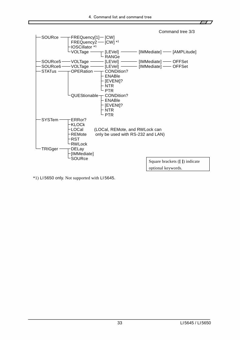
The LI 5645 / LI 5650 subsystem command tree is shown below.
<Root> Command tree 1/3
ABORt CALCulate1 FORMat MATH CURRent [LEVel] *1 EXPRession NAME VOLTage [LEVel] MULTiplier OFFSet AUTO ONCE STATe CALCulate2 FORMat MULTiplier OFFSet AUTO ONCE STATe CALCulate3 FORMat MULTiplier *1 OFFSet *1 AUTO ONCE *1 STATe *1 CALCulate4 FORMat MULTiplier *1 OFFSet *1 AUTO ONCE *1 STATe *1 CALCulate5 MATH EXPRession NAME *1 MULTiplier DATA COUNt? DATA? DELete ALL FEED CONTrol POINts TIMer STATe DISPlay [MENU] [NAME] WINDow [STATe] FETCh? FORMat [DATA] INITiate [IMMediate] INPut[1] COUPling FILTer NOTCh1 FREQuency [STATe] NOTCh2 [STATe] GAIN *1 LOW OFFSet AUTO ONCE RST STIMe
To be continued
Square brackets ([ ]) indicate
optional keywords.

4.Command list and command tree
32 LI 5645 / LI 5650
Command tree 2/3
INPut2 TYPE MEMory STATe DELete DEFine OUTPut[1] [STATe] OUTPut2 [STATe] OUTPut3 [STATe] OUTPut4 [STATe] ROUTe[1] [TERMinals] ROUTe2 [TERMinals] [SENSe] AUTO ONCE CURRent[1] AC RANGe AUTO *1 ONCE *1 [UPPer] *1 CURRent2 AC RANGe [UPPer] *1 DATA DETector [FUNCtion] *1 DREServe FILTer[1] [LPASs] AUTO ONCE SLOPe TCONstant TYPE FILTer2 [LPASs] SLOPe *1 TCONstant *1 TYPE *1 FREQuency[1] HARMonics MULTiplier SMULtiplier FREQuency2 *1 HARMonics *1 MULTiplier *1 NOISe [SMOothing] [APERture] PHASe[1] AUTO ONCE PHASe2 *1 AUTO ONCE *1 ROSCillator SOURce? VOLTage[1] AC RANGe AUTO ONCE [UPPer] VOLTage2 AC RANGe [UPPer] *1 VOLTage5 [DC] STATe TCONstant VOLTage6 [DC] STATe TCONstant
To be continued Square brackets ([ ]) indicate
optional keywords.
4.Command list and command tree
33 LI 5645 / LI 5650
Command tree 3/3
SOURce FREQuency[1] [CW] FREQuency2 [CW] *1 IOSCillator *1 VOLTage [LEVel] [IMMediate] [AMPLitude] RANGe SOURce5 VOLTage [LEVel] [IMMediate] OFFSet SOURce6 VOLTage [LEVel] [IMMediate] OFFSet STATus OPERation CONDition? ENABle [EVENt]? NTR PTR QUEStionable CONDition? ENABle [EVENt]? NTR PTR SYSTem ERRor? KLOCk LOCal (LOCal, REMote, and RWLock can REMote only be used with RS-232 and LAN) RST RWLock TRIGger DELay [IMMediate] SOURce
*1) LI 5650 only. Not supported with LI 5645.
Square brackets ([ ]) indicate
optional keywords.

4.Command list and command tree
34 LI 5645 / LI 5650

35 LI 5645 / LI 5650
5. Command explanation

5.Command explanation
36 LI 5645 / LI 5650
5.1 Language outline
resents an outline of the language.
5.1.1 Subsystem commands
Commands are grouped according to function. Subsystem commands are ordered hierarchically, with
the colon (:) defined as the path separator.
5.1.2 Path separator
The path separator (:) delimits the current keyword from keywords at the next lower level. Each time a
colon (:) is detected in a command string, the current path shifts to the next lower level.
Using a colon (:) at the beginning of a command string means "set the current path as root." The root
path is also set when the power is turned on, or by the *RST command or a message terminator.
Program messages always have the root at the beginning. Also, the colon (:) may be omitted from the
beginning of command strings.
: S Y S T: K L O C 1
① Set current path as root (optional).
② SYSTem subsystem commands (SYSTem is a root command).
③ KLOCk command is included in the SYSTem subsystem.
④ A space is required between header and parameters.
Multiple command strings can be included in a single program message by delimiting them with
semicolons (;).
:SENS:FILT1:LPAS:SLOP 12 ; :SENS:FILT1:LPAS:TCON 0.1
Command1 Command2
The above is the equivalent of the following two program messages.
:SENS:FILT1:LPAS:SLOP 12
Current path following execution is : SENS:FILT1:LPAS
Subsystem commands at the same level as the first command can be accessed by omitting the
colon (:) from the beginning of the second and following command strings.
:SENS:FILT1:LPAS:SLOP 12 ; TCON 0.1
:SENS:FILT1:LPAS: can be omitted from the second command string
In any case, the concluding program message terminator can be omitted.
Note that the current path may change if a keyword is omitted.
↑
①
↑
②
↑
③
↑
④

5.Command explanation
37 LI 5645 / LI 5650
5.1.3 Abbreviation of keywords
In this instruction manual, commands and parameters are described using combinations of upper and
lowercase alphabetic characters. Uppercase characters indicate the short (abbreviated) form. Commands
from which lowercase characters are omitted have the same functionality as long-form commands that
include lowercase characters. However, omission of just part of lowercase letters is not possible.
The use of upper and lowercase characters is a matter of presentation convenience, and there is no
distinction between the two at the device level. Upper and lowercase letters can be freely mixed.
Example) Command notation CALCulate1 FORMat?
→ :calculate1:format? Valid - Long form, all lowercase letters
:Calc1:Form? Valid - Short form, mixed upper and lowercase letters
:CALCUL1:FORM? Invalid - Partially abbreviated
:CALC1:FOR? Invalid - Excessive abbreviation
5.1.4 Optional keywords
Keywords appearing in square brackets ([ ]) are optional. Device operation is the same regardless of
optional keywords are all included or are partially or totally omitted. The two examples below both
perform the same function on the device.
Example) Command notation DISPlay[:MENU][:NAME] NORMal
→ :DISP:MENU:NAME NORM No keywords omitted
:DISP NORM Keywords omitted
5.2 Sequential commands
All LI 5645 / LI 5650 commands are sequential commands. Commands are executed in sequence, with
execution of later commands following that of preceding commands. There are no overlapping
commands.

5.Command explanation
38 LI 5645 / LI 5650
5.3 Detailed command explanations
Functions and command syntax of commands shown in "Table 1 Common commands" and "Table 2
Subsystem command list" are explained below.
[Meaning of symbols]
・ Square brackets ([ ]) indicate optional keywords. (Implied keywords)
・ Braces ({ }) enclose the parameters of the command string.
・ Vertical bars ( | ) are used to indicate a choice from among multiple keywords.
・ Angle brackets (< >) are used to indicate required parameters consisting of numerics or
text.
These symbols are used purely for the sake of explanation, are must not be included in actual
commands.
Explanation :DISPlay:WINDow[:STATe] {ON|OFF|1|0}
Actual command :DISPlay:WINDow:STATe ON
[Parameter format]
Symbol Format Example
NR1 Integer (numeric) 123
NR2 Decimal format without an exponent
(numeric)
0.075
NR3 Decimal format with an exponent (numeric) 4.99E+06
CRD Character string ALL
SRD Character string enclosed in double quotation
marks
"No error"
bool Logical value ON, OFF, 1, 0
・Unless otherwise specified, numbers may be specified in any format, and values
specified are rounded to the nearest value if the specified value exceeds the permitted
resolution. Further, when a numerical value is set that is not included in the parameter
options, it is rounded to the closest value.
・Unless otherwise specified, the minimum numeric value is assumed for numbers that are
less than the minimum value, and the maximum numeric value is assumed for numbers
that exceed the maximum.
・With numeric parameters for which specification of MAX / MIN is allowed, the
maximum numeric value is set when MAX (or MAXIMUM) is specified, and the
minimum numeric value is set for MIN (or MINIMUM).
・When the response is a numeric value and the range, resolution, and unit have not been
specified, those parameters are the same as in the configuration. Unless otherwise
specified, the mantissa of the NR3 format responses has 6 digits.
・For commands whose parameter type varies according to specification format, numbers
specified that exceed the ranges indicated are lumped into the same range and resolution
as for operation from the panel. For the actual range of numeric that can be set, refer to
the panel operating instructions.
・Quotation marks used to enclose character strings can be either single quotation marks or
double quotation marks.

5.Command explanation
39 LI 5645 / LI 5650
[Notes]
・In this explanation, the work "command" refers to both commands and to queries.
Keywords which conclude with a question mark (?) are queries.
・No headers are attached to messages sent in response to commands.

5.Command explanation
40 LI 5645 / LI 5650
5.3.1 Common commands
*CLS
Explanation Clears the following statuses.
・ Standard Event Status register
・ Operation Event register
・ Questionable Event register
・ Status byte
・ Error queue
Also clears the panel error display.
Setting example *CLS
Note The *CLS does not clear the Status Byte register directly. However, except for
the MAV bit and RQS bit, the status byte is cleared indirectly. The MAV bit is
cleared indirectly when the input buffer is cleared by Device Clear. The RQS
bit can be cleared by reading the status through serial polling.
*ESE <mask>
*ESE?
Explanation Sets and queries the Standard Event Status Enable register.
Parameter(s) <mask> {numeric, range 0 to 255} An error results if range exceeded.
For details "6.3 Standard event status"
Setting example *ESE 32
Sets 32 to the Standard Event Status Enable register.
Response <mask> {numeric, format NR1, range 0 to 255}
Query example *ESE?
Response example 32
The Standard Event Status Enable register contains 32.
*ESR?
Explanation Queries content of the Standard Event Status register.
Upon querying the Standard Event Status register, all of its bits are cleared to
0.
Response <Register content> {numeric, format NR1, range 0 to 255}
For details "6.3 Standard event status"
Query example *ESR?
Response example 16
The Standard Event Status Enable register contains 16.

5.Command explanation
41 LI 5645 / LI 5650
*IDN?
Explanation Queries the model name.
Response {"<manufacturer name>, <model name>, <serial number>, <firmware
version>"}
Format SRD
Query example *IDN?
Response example "NF Corporation,LI5650,9097772,Ver1.00"
*OPC
*OPC?
Explanation Verifies that execution of all preceding commands has been completed.
Setting example *OPC
Specifies that the OPC bit of the Standard Event Status register be set to 1
when execution of all preceding commands has been completed. Completion of
command execution can be verified by monitoring the status.
Explanation 1
1 is returned when execution of all preceding commands has been completed.
Query example *OPC?
Explanation 1
Execution of all preceding commands has been completed.
Note *OPC? does not clear the Standard Event Status register's OPC bit. To clear the
bit, use Device Clear or the *CLS or *RST command.
The OPC bit can be used to trigger SRQ when it becomes 1.
*RCL <memory number>
Explanation Restores the settings stored in the specified configuration memory.
Parameter(s) <memory number> {numeric in range 0 to 9} An error results if range
exceeded.
When 0 is specified, settings are restored to the power-on settings (the settings
at time of power-off). Default settings are written in configuration memories
that have not been used to store settings.
Setting example *RCL 5
Restores the settings stored in configuration memory 5.
Note An error occurs if the contents of the specified configuration memory have
been corrupted.
*RST
Explanation Restores default settings.
For details LI 5645 / LI 5650 Instruction Manual (Operations)
"Table 3-2 Settings and default values"
Setting example *RST

5.Command explanation
42 LI 5645 / LI 5650
*SAV <memory number>
Explanation Saves current settings to the specified configuration memory.
Parameter(s) <memory number> {numeric in range 1 to 9} An error results if range
exceeded.
Setting example *SAV 5
Saves current settings to configuration memory 5.
Note Contents of configuration memory are not cleared by the *RST command.
To clear contents of configuration memory, :SYSTem:RST command
*SRE <SRQ mask>
*SRE?
Explanation Sets and queries the Service Request Enable register.
Parameter(s) <SRQ mask> {numeric in range 0 to 255} An error results if range
exceeded.
For details "6.1 Status system outline"
Setting example *SRE 128
Response {numeric, format NR1, range 0 to 255}
Query example *SRE?
Response example 128
The Service Request Enable register contains 128.
*STB?
Explanation Queries content of the Status Byte register.
Response <Register content> {numeric, format NR1, range 0 to 255}
For details "6.2 Status byte"
Query example *STB?
Response example 128
The Status Byte register contains 128.
*TRG
Explanation When the measurement data buffer is enabled, executes a trigger and records
data in the measurement buffer.
When the internal timer is disabled, measurement data is recorded only once.
When the internal timer is enabled, starts recording measurement data
according to the internal timer.
Enable the measurement data buffer :DATA:FEED:CONTrol command
Set the internal timer :DATA:TIMer command
Before using triggers, the awaiting trigger state must be set with
the :INITiate[:IMMediate] command. An error will result if the awaiting
trigger state has not been set.
Setting example *TRG
Executes a trigger.

5.Command explanation
43 LI 5645 / LI 5650
*TST?
Explanation Queries results of the internal self-diagnostic.
Response {numeric, format NR1, range 0}
Query example TST?
Response example 0
Note With this device, the response is always 0. It is not possible to check the
internal status by external control. Check on the panel operation.
For details LI 5645 / LI 5650 Instruction Manual (Operations)
"8.5 Self-diagnostic"
*WAI
Explanation Postpones execution of ensuing commands until execution of all commands
has been completed.
Example of use Command 1; command 2; *WAI; following commands <program message
terminator>
Following commands are executed after completion of execution of both
command 1 and command 2.
Note The wait state applied by the *WAI command is cleared by Device Clear.
With this equipment, there are no applicable overlapping commands.
5.Command explanation
44 LI 5645 / LI 5650
5.3.2 Subsystem commands
:ABORt
Explanation Aborts recording to the measurement data buffer and puts the trigger system in
the idle state.
Setting example :ABOR
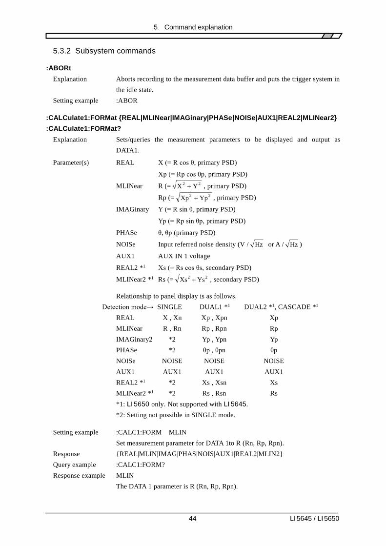
:CALCulate1:FORMat {REAL|MLINear|IMAGinary|PHASe|NOISe|AUX1|REAL2|MLINear2}
:CALCulate1:FORMat?
Explanation Sets/queries the measurement parameters to be displayed and output as
DATA1.
Parameter(s) REAL X (= R cos θ, primary PSD)
Xp (= Rp cos θp, primary PSD)
MLINear R (= 22YX , primary PSD)
Rp (= 22YpXp , primary PSD)
IMAGinary Y (= R sin θ, primary PSD)
Yp (= Rp sin θp, primary PSD)
PHASe θ, θp (primary PSD)
NOISe Input referred noise density (V / Hz or A / Hz )
AUX1 AUX IN 1 voltage
REAL2 *1 Xs (= Rs cos θs, secondary PSD)
MLINear2 *1 Rs (= 22YsXs , secondary PSD)
Relationship to panel display is as follows.
Detection mode→ SINGLE DUAL1 *1 DUAL2 *1, CASCADE *1
REAL X , Xn Xp , Xpn Xp
MLINear R , Rn Rp , Rpn Rp
IMAGinary2 *2 Yp , Ypn Yp
PHASe *2 θp , θpn θp
NOISe NOISE NOISE NOISE
AUX1 AUX1 AUX1 AUX1
REAL2 *1 *2 Xs , Xsn Xs
MLINear2 *1 *2 Rs , Rsn Rs
*1: LI 5650 only. Not supported with LI 5645.
*2: Setting not possible in SINGLE mode.
Setting example :CALC1:FORM MLIN
Set measurement parameter for DATA 1to R (Rn, Rp, Rpn).
Response {REAL|MLIN|IMAG|PHAS|NOIS|AUX1|REAL2|MLIN2}
Query example :CALC1:FORM?
Response example MLIN
The DATA 1 parameter is R (Rn, Rp, Rpn).

5.Command explanation
45 LI 5645 / LI 5650
Note Measurement parameters REAL2 and MLIN2 cannot be selected with the
LI 5645.
:CALCulate1:MATH:CURRent[:LEVel] <reference value>
:CALCulate1:MATH:CURRent[:LEVel]?
Explanation Sets/queries the current reference value for normalize calculation.
Parameter(s) <reference value> {numeric, range +1E-15 to +1E-06, resolution 6 digits,
unit Arms}
Setting example :CALC1:MATH:CURR 1.23456E-6
Sets the current reference value for normalize calculation to 1.23456E-6 Arms.
Response {numeric, format NR3}
Query example :CALC1:MATH:CURR?
Response example 1.000000E-06
The current reference value for normalize calculation is 1µArms.
Note This command cannot be used with the LI 5645. An error will result.
:CALCulate1:MATH:EXPRession:NAME {DB|PCNT|PCFS} [,"Unit"]
:CALCulate1:MATH:EXPRession:NAME?
Explanation Sets/queries the normalize calculation format.
Display and output of normalize results also requires enabling normalize
calculation with the :CALCulate5:MATH NORM command.
Reference values are set with
:CALCulate:MATH:CURRent[:LEVel] command (current) and
:CALCulate:MATH:VOLTage[:LEVel] command (voltage)
Parameter(s) DB The measured value is shown as a log ratio with respect to the
reference value.
20 × log10 (measurement value / reference value), unit dB
PCNT Measurement value displayed as percentage of reference value.
(measurement value / reference value) × 100, unit %
PCFS Measurement value displayed as percentage of sensitivity (full
scale).
(measurement value / sensitivity) × 100, unit % of FS (display
is %FS)
"Unit" Specify an alphanumeric character string of up to 3 characters.
When specified, the string is displayed instead of dB or %.
Characters allowed are {A to Z, a to z, 0 to 9, #, @, -, (space)}
Setting example :CALC1:MATH:EXPR:NAME DB ,"dBv"
Sets dB as the normalize calculation format and dBv for unit display.
Response {DB|PCNT|PCFS}[,<Unit>]
If a character string has been set for unit display, that string is included in the
response.
Query example :CALC1:MATH:EXPR:NAME?

5.Command explanation
46 LI 5645 / LI 5650
Response DB ,"dBv"
Normalize calculation format is dB, and unit display is dBv.
:CALCulate1:MATH:VOLTage[:LEVel] <reference value>
:CALCulate1:MATH:VOLTage[:LEVel]?
Explanation Sets/queries the voltage reference value for normalize calculation.
Parameter(s) <reference value> {numeric, range +1E-9 to +1E+1, resolution 6 digits, unit
Vrms}
Setting example :CALC1:MATH:VOLT 1.23456E-6
Sets the voltage reference value for normalize calculation to 1.23456E-6 Vrms.
Response {numeric, format NR3}
Query example :CALC1:MATH:VOLT?
Response example 1.000000E-06
The voltage reference value for normalize calculation is 1µVrms.
:CALCulate1:MULTiplier <multiplier>
:CALCulate1:MULTiplier?
Explanation Sets/queries the primary PSD R, X output common EXPAND multiplier.
Display and output of EXPAND results also requires
enabling EXPAND calculation with the :CALCulate5:MATH EXP command.
Parameter(s) <multiplier>:{1|10|100}
Setting example :CALC1:MULT 10
Sets primary PSD R, X output common EXPAND multiplier to 10.
The effective sensitivity (full scale) is 1/10 of the setting.
Response <multiplier> {numeric, format NR1}
Query example :CALC1:MULT?
Setting example 10
primary PSD R, X output common EXPAND multiplier is 10.
Note The EXPAND multiplier only affects X, Y, R. It does not affect other
parameters.

5.Command explanation
47 LI 5645 / LI 5650
:CALCulate1:OFFSet <offset>
:CALCulate1:OFFSet?
Explanation Sets/queries the offset for the primary PSD's X output.
For offset adjustment, also enable offset with the
:CALCulate1:OFFSet:STATe ON command.
Parameters <offset> {numeric, range -105 to +105, resolution 0.001, unit %}
% is with respect to sensitivity full scale.
Setting example :CALC1:OFFS 43
The offset for X is 43% of sensitivity full scale.
The equivalent of 43% of full scale is subtracted from the original X value.
Response <offset> {numeric, format NR3}
Query example :CALC1:OFFS?
Response example 4.300000E+01
The X offset is 43%.
Note The EXPAND multiplier is applied after offset adjustment.
Unless otherwise specified, the mantissa of the NR3 format responses has 6
digits.
:CALCulate1:OFFSet:AUTO:ONCE
Explanation Automatically sets the X offset and Y offset so that primary PSD's X output
and Y output at that point become zero, and enables offset adjustment.
Setting example :CALC1:OFFS:AUTO:ONCE
Automatically adjusts offset so that X output and Y output become zero.
Note If the range of possible adjustment is exceeded, adjustment is made within the
possible range.
:CALCulate1:OFFSet:STATe {ON|OFF|1|0}
:CALCulate1:OFFSet:STATe?
Explanation Sets whether offset is adjusted for the primary PSD's X output.
Parameter(s) {ON|1} Enables offset adjustment.
{OFF|0} Disables offset adjustment.
Setting example :CALC1:OFFS:STAT ON
Enables X offset adjustment.
Response {1|0}
Query example :CALC1:OFFS:STAT?
Response example 1
X offset adjustment is enabled.

5.Command explanation
48 LI 5645 / LI 5650
:CALCulate2:FORMat {IMAGinary|PHASe|AUX1|AUX2|REAL2|MLINear2|
IMAGinary2|PHASe2}
:CALCulate2:FORMat?
Explanation Sets/queries the measurement parameters to be displayed and output as
DATA2.
Parameter(s) IMAGinary Y (= R sin θ, primary PSD)
Yp (= Rp sin θp, primary PSD)
PHASe θ, θp (primary PSD)
AUX1 AUX IN 1 voltage
AUX2 AUX IN 2 voltage
REAL2 *1 Xs (= Rs cos θs, secondary PSD)
MLINear2 *1 Rs (= 22YsXs , secondary PSD)
IMAGinary2 *1 Ys (= Rs sin θs, secondary PSD)
PHASe2 *1 θ, θs (secondary PSD)
Relationship to panel display is as follows.
Detection mode→ SINGLE DUAL1 *1 DUAL2 *1, CASCADE *1
IMAGinary Y , Yn Yp , Ypn Yp
PHASe θ , θn θp ,θpn θp
AUX1 AUX1 AUX1 AUX1
AUX2 AUX2 AUX2 AUX2
REAL2 *1 *2 Xs , Xsn Xs
MLINear2 *1 *2 Rs , Rsn Rs
IMAGinary2 *1 *2 Ys , Ysn Ys
PHASe2 *1 *2 θs , θsn θs
*1: LI 5650 only. Not supported with LI 5645.
*2: Setting not possible in SINGLE mode.
Setting example :CALC2:FORM PHAS
Set measurement parameter for DATA 2 to θ (θn, θp, θpn).
Response {IMAG|PHAS|AUX1|AUX2|REAL2|MLIN2|IMAG2|PHAS2}
Query example :CALC2:FORM?
Response example PHAS
DATA 2 measurement parameters are θ (θn, θp, θpn).
Note Measurement parameters REAL2, MLIN2, IMAG2 and PHAS2 cannot be
selected with the LI 5645.

5.Command explanation
49 LI 5645 / LI 5650
:CALCulate2: MULTiplier <multiplier>
:CALCulate2: MULTiplier?
Explanation Sets/queries the primary PSD's Y output EXPAND multiplier.
Display and output of EXPAND results also requires
enabling EXPAND calculation with the :CALCulate5:MATH EXP command.
Parameter(s) <multiplier>:{1|10|100}
Setting example :CALC2:MULT 10
Sets primary PSD output EXPAND multiplier to 10.
The effective sensitivity (full scale) is 1/10 of the setting.
Response <multiplier> {numeric, format NR1}
Query example :CALC2:MULT?
Response example 10
primary PSD's Y output common EXPAND multiplier is 10.
Note The multiplier only affects X, Y, R. It does not affect other parameters.
:CALCulate2:OFFSet <offset>
:CALCulate2:OFFSet?
Explanation Sets/queries the offset for the primary PSD's Y output.
For offset adjustment, also enable offset with the
:CALCulate2:OFFSet:STATe ON command.
Parameters <offset> {numeric, range -105 to +105, resolution 0.001, unit %}
% is with respect to sensitivity (full scale).
Setting example :CALC2:OFFS 43
The offset for Y is 43% of sensitivity full scale.
The equivalent of 43% is subtracted from the original Y value.
Response <offset> {numeric, format NR3}
Query example :CALC2:OFFS?
Response example 4.300000E+01
The Y offset is 43%.
Note The EXPAND multiplier is applied after offset adjustment.
:CALCulate2:OFFSet:AUTO:ONCE
Explanation Automatically sets the X offset and Y offset so that primary PSD's X output
and Y output at that point become zero.
Setting example :CALC2:OFFS:AUTO:ONCE
Automatically adjusts offset so that X output and Y output become zero.
Note This function is the same as that of the :CALCulate1:OFFSet:AUTO:ONCE
command. Both of these commands work on both X and Y. Automatic setting
of just X or just Y is not possible.

5.Command explanation
50 LI 5645 / LI 5650
:CALCulate2:OFFSet:STATe {ON|OFF|1|0}
:CALCulate2:OFFSet:STATe?
Explanation Sets whether offset is adjusted for primary PSD's Y output.
Parameter(s) {ON|1} Enables offset adjustment.
{OFF|0} Disables offset adjustment.
Setting example :CALC2:OFFS:STAT ON
Enables Y offset adjustment.
Response {1|0}
Query example :CALC2:OFFS:STAT?
Response example 1
Y offset adjustment is enabled.
:CALCulate3:FORMat {REAL|MLINear|IMAGinary|PHASe|REAL2|MLINear2}
:CALCulate3:FORMat?
Explanation Sets/queries the measurement parameters to be displayed and output as
DATA3.
Parameter(s) REAL X , Xp (primary PSD)
MLINear R , Rp (primary PSD)
IMAGinary Y , Yp (primary PSD)
PHASe θ , θp (primary PSD)
REAL2 *1 Xs (secondary PSD)
MLINear2 *1 Rs (secondary PSD)
Relationship to panel display is as follows.
Detection mode→ SINGLE DUAL1 *1 DUAL2 *1, CASCADE *1
REAL X , Xn Xp , Xpn Xp
MLINear R , Rp Rp , Rpn Rp
IMAGinary *2 Yp , Ypn Yp
PHASe *2 θp , θpn θp
REAL2 *1 *2 Xs , Xsn Xs
MLINear2 *1 *2 Rs , Rsn Rs
*1: LI 5650 only. Not supported with LI 5645.
*2: Setting not possible in SINGLE mode.
Setting example :CALC3:FORM REAL
Set measurement parameter for DATA 3 to X (Xn, Xp, Xpn).
Response {REAL|MLIN|IMAG|PHAS|REAL2|MLIN2}
Query example :CALC2:FORM?
Response example REAL
Measurement parameter for DATA 3 is X (Xn, Xp, Xpn).
Note Measurement parameters REAL2 and MLIN2 cannot be selected with the
LI 5645.

5.Command explanation
51 LI 5645 / LI 5650
:CALCulate3 :MULTiplier <multiplier>
:CALCulate3:MULTiplier?
Explanation Sets/queries the secondary PSD's R, X output common EXPAND multiplier.
Display and output of EXPAND results also requires
enabling EXPAND calculation with the :CALCulate5:MATH EXP command.
Parameter(s) <multiplier>:{1|10|100}
Setting example :CALC3:MULT 10
Sets secondary PSD R, X output common EXPAND multiplier to 10.
The effective sensitivity (full scale) is 1/10 of the setting.
Response <multiplier> {numeric, format NR1}
Query example :CALC3:MULT?
Setting example 10
Secondary PSD R, X output common EXPAND multiplier is 10.
Note This command cannot be used with the LI 5645. An error will result.
:CALCulate3:OFFSet <offset>
:CALCulate3:OFFSet?
Explanation Sets/queries the offset with respect to the secondary PSD's X output.
For offset adjustment, also enable offset with the
:CALCulate3:OFFSet:STATe ON command.
Parameters <offset> {numeric, range -105 to +105, resolution 0.001, unit %}
% is with respect to sensitivity full scale.
Setting example :CALC3:OFFS 43
Sets the offset with respect to secondary PSD X output to 43% of sensitivity
full scale.
The equivalent of 43% is subtracted from the original X value.
Response <offset> {numeric, format NR3}
Query example :CALC3:OFFS?
Response example 4.300000E+01
The offset with respect to secondary PSD X output is 43% of sensitivity full
scale.
Note This command cannot be used with the LI 5645. An error will result.
:CALCulate3:OFFSet:AUTO:ONCE
Explanation Automatically sets offset so that secondary PSD's X and Y output become zero.
Setting example :CALC3:OFFS:AUTO:ONCE
Automatically adjusts offset so that secondary PSD's X and Y outputs become
zero.
Note This command cannot be used with the LI 5645. An error will result.
If the range of possible adjustment is exceeded, adjustment is made within the
possible range.

5.Command explanation
52 LI 5645 / LI 5650
:CALCulate3:OFFSet:STATe {ON|OFF|1|0}
:CALCulate3:OFFSet:STATe?
Explanation Sets whether offset is adjusted with respect to the secondary PSD's X output.
Parameter(s) {ON|1} Enables offset adjustment.
{OFF|0} Disables offset adjustment.
Setting example :CALC3:OFFS:STAT ON
Enables offset adjustment for the secondary PSD's X output.
Response {1|0}
Query example :CALC3:OFFS:STAT?
Response example 1
Secondary PSD’s X offset adjustment is enabled.
Note This command cannot be used with the LI 5645. An error will result.
:CALCulate4:FORMat {IMAGinary|PHASe|REAL2|MLINear2|IMAGinary2|PHASe2}
:CALCulate4:FORMat?
Explanation Sets/queries the measurement parameters to be displayed and output as
DATA4.
Parameter(s) IMAGinary Y, Yp (primary PSD)
PHASe θ, θp (primary PSD)
REAL2 *1 Xs (secondary PSD)
MLINear2 *1 Rs (secondary PSD)
IMAGinary2 *1 Ys (secondary PSD)
PHASe2 *1 θs (secondary PSD)
Relationship to panel display is as follows.
Detection mode→ SINGLE DUAL1 *1 DUAL2 *1, CASCADE *1
IMAGinary Y , Yn Yp , Ypn Yp
PHASe θ , θn θp , θpn θp
REAL2 *1 *2 Xs , Xsn Xs
MLINear2 *1 *2 Rs , Rsn Rs
IMAGinary2 *1 *2 Ys , Ysn Ys
PHASe2 *1 *2 θs , θsn θs
*1: LI 5650 only. Not supported with LI 5645.
*2: Setting not possible in SINGLE mode.
Setting example :CALC4:FORM IMAG
Set measurement parameter for DATA 4 to Y (Yn, Yp, Ypn).
Response {IMAG|PHAS|REAL2|MLIN2|IMAG2|PHAS2}
Query example :CALC4:FORM?
Response example IMAG
Measurement parameter for DATA 4 is Y (Yn, Yp, Ypn).
Note Measurement parameters REAL2, MLIN2, IMAG2 and PHAS2 cannot be
selected with the LI 5645.
5.Command explanation
53 LI 5645 / LI 5650
:CALCulate4:MULTiplier <multiplier>
:CALCulate4:MULTiplier?
Explanation Sets/queries the secondary PSD's Y output EXPAND multiplier.
Display and output of EXPAND results also requires
enabling EXPAND calculation with the :CALCulate5:MATH EXP command.
Parameter(s) <multiplier>:{1|10|100}
Setting example :CALC4:MULT 10
Sets secondary PSD output EXPAND multiplier to 10.
The effective sensitivity (full scale) is 1/10 of the setting.
Response <multiplier> {numeric, format NR1}
Query example :CALC4:MULT?
Response example 10
Secondary PSD's Y output common EXPAND multiplier is 10.
Note This command cannot be used with the LI 5645. An error will result.
:CALCulate4:OFFSet <offset>
:CALCulate4:OFFSet?
Explanation Sets/queries the offset for the secondary PSD's Y output.
For offset adjustment, also enable offset with the
:CALCulate4:OFFSet:STATe ON command.
Parameters <offset> {numeric, range -105 to +105, resolution 0.001, unit %}
% is with respect to sensitivity full scale.
Setting example :CALC4:OFFS 43
Sets the offset with respect to secondary PSD Y output to 43% of sensitivity
full scale.
The equivalent of 43% is subtracted from the original Y value.
Response <offset> {numeric, format NR3}
Query example :CALC4:OFFS?
Response example 4.300000E+01
The offset with respect to secondary PSD Y output is 43% of sensitivity full
scale.
Note This command cannot be used with the LI 5645. An error will result.
:CALCulate4:OFFSet:AUTO:ONCE
Explanation Automatically sets offset so that secondary PSD's X and Y output become zero.
Setting example :CALC4:OFFS:AUTO:ONCE
Automatically adjusts offset so that secondary PSD's X and Y outputs become
zero.
Note This command cannot be used with the LI 5645. An error will result.
This function is the same as that of the :CALCulate3:OFFSet:AUTO:ONCE
command. Both of these commands work on both X and Y. Automatic setting
of just X or just Y is not possible.

5.Command explanation
54 LI 5645 / LI 5650
:CALCulate4:OFFSet:STATe {ON|OFF|1|0}
:CALCulate4:OFFSet:STATe?
Explanation Sets whether offset is adjusted for secondary PSD's Y output.
Parameter(s) {ON|1} Enables offset adjustment.
{OFF|0} Disables offset adjustment.
Setting example :CALC4:OFFS:STAT ON
Enables offset adjustment for the secondary PSD's Y output.
Response {1|0}
Query example :CALC4:OFFS:STAT?
Response example 1
Secondary PSD’s Y offset adjustment is enabled.
Note This command cannot be used with the LI 5645. An error will result.
:CALCulate5:MATH {OFF|EXPand|NORMalize|RATio}
:CALCulate5:MATH?
Explanation Sets/queries the calculation method for measurement value to be displayed and
output.
One method can be selected from among EXPAND, normalize calculation, and
ratio calculation.
Parameter(s) OFF No calculation is performed on the measurement value.
EXPand Enables EXPAND (enlarge).
NORMalize Enables normalize calculation
RATio Enables ratio calculation.
Setting example :CALC5:MATH EXP
Enables EXPAND.
Response {OFF|EXP|NORM|RAT}
Query example :CALC5:MATH?
Response example OFF
Calculation is not performed on measurement values.

5.Command explanation
55 LI 5645 / LI 5650
:CALCulate5:MATH:EXPRession:NAME {RATio|RATio2}
:CALCulate5:MATH:EXPRession:NAME?
Explanation Sets/queries the ratio calculation format.
Display and output of results also requires enabling ratio calculation with
the :CALCulate5:MATH RATio command.
Parameter(s) RATio: Normal ratio calculation (denominator: AUX IN 1)
This can be used with every detection mode.
Result (In SINGLE, DUAL1, or DUAL2 mode) =
Ratio multiplier
× primary PSD output (X, Y, R [% of FS])
/ AUX IN 1 [% of FS]
Result (In CASCADE mode) =
Ratio multiplier
× secondary PSD output (X, Y, R [% of FS])
/ AUX IN 1 [% of FS]
RATio2: Expanded ratio calculation (denominator: secondary PSD output)
Can only be used with DUAL1 and DUAL2 detection modes.
Result =
Ratio multiplier
× primary PSD output (X, Y, R [% of FS])
/ secondary PSD output [X % of FS]
Setting example :CALC5:MATH:EXPR:NAME RAT
Sets RATio as the calculation format.
Response {RAT|RAT2}
Query example :CALC5:MATH:EXPR:NAME?
Response example RAT
The ratio calculation format is RATio.
Note When the ratio calculation is invalid, the ratio calculation is not carried, it does
not result in an error.

5.Command explanation
56 LI 5645 / LI 5650
:CALCulate5 :MULTiplier <factor>
:CALCulate5:MULTiplier?
Explanation Sets/queries the ratio multiplier.
Parameter(s) <factor> {numeric, range 0.10000 to 10.00000, resolution 0.00001}
Setting example :CALC5:MULT 2
Sets the ratio multiplier to 2.
Response {numeric, format NR3}
Query example :CALC5:MULT?
Response example 2.000000E+00
The ratio multiplier is 2.
:DATA:COUNt? {BUF1|BUF2|BUF3}
Explanation Queries the number of data sampling points recorded in the measurement data
buffer.
Parameter(s) BUF1 Indicates that measurement data buffer 1 is to be queried.
BUF2 Indicates that measurement data buffer 2 is to be queried.
BUF3 Indicates that measurement data buffer 3 is to be queried.
Response <number of sample points>
BUF1, BUF2 {numeric, format NR1, range 0 to 8192 }
BUF3 {numeric, format NR1, range 0 to 65536 }
Query example :DATA:COUN? BUF1
Response example 256
The number of measurement data samples recorded in measurement data
buffer 1 is 256.
Note When the measurement data buffer is empty, the response is 0.
Clearing the measurement data buffer :DATA:DELete command

5.Command explanation
57 LI 5645 / LI 5650
:DATA:DATA? {BUF1|BUF2|BUF3} [, <block length>[,<start position>]]
Explanation Queries the contents of the measurement data buffer (the measurement values).
Parameter(s) BUF1 Indicates that measurement data buffer 1 is to be queried.
BUF2 Indicates that measurement data buffer 2 is to be queried.
BUF3 Indicates that measurement data buffer 3 is to be queried.
<block length>
{numeric, format NR1, range 1 .. buffer size }
Sets the block length of measurement data to be acquired from the buffer (the
number of sample points).
Measurement data is separated into blocks for transmission.
If the block length is omitted, all of the measurement data is returned as a
single block.
Setting the measurement data buffer size :DATA:POINts command
<start position>
{numeric, format NR1, range 0 .. buffer size-1}
Specifies the start position of measurement data to be acquired.
If omitted, data is acquired from the recording start position.
This specification is invalid if used with BUF3.
Response Content of BUF1, BUF2, or BUF3
<measurement data block>
<measurement data set a>[, <measurement data set a+1>,
.. , <measurement data set a+(b-1)>] <message terminator>
a: Specified record start position
b: Specified block length

5.Command explanation
58 LI 5645 / LI 5650
<measurement data set>
[STATUS], [DATA1], [DATA2], [DATA3], [DATA4], [FREQ]
This is a set of measurements for one sample point.
Content specification :DATA:FEED command
STATUS {numeric, range 0 to 31}
0 No abnormality
1 PROTECT
Voltage a signal input connector A or B exceeds rated limit.
2 INPUT
Over level somewhere from the signal input connector to the PSD
4 OUTPUT
Over level at a time constant filter, amplification, or calculation
downstream from the PSD.
8 AUX
Maximum input voltage exceeded at AUX IN 1 or 2.
16 UNLOCK
The reference signal source is REF IN or SIGNAL and is not
synchronized.
DATA1, DATA2, DATA3, DATA4, FREQ
Data transfer formats for each value :FORMat[:DATA] command
The measurement data block and measurement data set above show the
format in ASCII. The sequence of values are the same for both real
numbers and integers, but commas are not used to delimit values, no
message terminator is appended, and a single measurement data block is
transferred as a single fixed length data block.
Note If the number of measurement data sets from the specified start position do not
fill the specified block length, remaining places in the measurement data set
are filled with zeros.
When the content of BUF3 is queried, measurement data blocks are sent
starting with the oldest data. The data read is deleted from the measurement
data buffer, releasing a proportionate amount of space in the buffer (First In,
First Out).
Query example :DATA:DATA? BUF1
Response example 2.732512E-01, 1.215909E+02, 2.733309E-01, 1.215591E+02, ...
Deriving the actual value :FORMat[:DATA] command
(When :DATA:FEED BUF1,6;:FORM ASC is set taking DATA1 as R, DATA2
as )

5.Command explanation
59 LI 5645 / LI 5650
:DATA:DELete {BUF1|BUF2|BUF3}
Explanation Clears the specified measurement data buffer.
Parameter(s) BUF1 Clears measurement data buffer 1.
BUF2 Clears measurement data buffer 2.
BUF3 Clears measurement data buffer 3.
Setting example :DATA:DEL BUF1
Clears measurement data buffer 1.
:DATA:DELete:ALL
Explanation Clears all measurement data buffers.
Setting example :DATA:DEL:ALL
Clears measurement data buffers 1, 2, and 3.
Note Clearing a specified measurement data buffer :DATA:DELete command
:DATA:FEED {BUF1|BUF2|BUF3}, <measurement data>
:DATA:FEED? {BUF1|BUF2|BUF3}
Explanation Sets/queries measurement data sets recorded in measurement data buffer 1, 2,
or 3. Recording of measurement data is specified separately using
the :DATA:FEED:CONT command.
Parameter(s) BUF1 Indicates that measurement data buffer 1 is to be set/queried.
BUF2 Indicates that measurement data buffer 2 is to be set/queried.
BUF3 Indicates that measurement data buffer 3 is to be set/queried.
<measurement data>
{numeric, range 0 to 63}
1 STATUS (16 bits = 1 word)
Records the measurement status.
Measurement status content :DATA:DATA command
2 DATA1 (16 bits = 1 word)
Records the value of DATA1.
4 DATA2 (16 bits = 1 word)
Records the value of DATA2.
8 DATA3 (16 bits = 1 word)
Records the value of DATA3.
16 DATA4 (16 bits = 1 word)
Records the value of DATA4.
32 FREQ (32 bits = 2 words)
Records the frequency value.
The fundamental wave or primary frequency is recorded when
the detection mode is SINGLE, DUAL1, or DUAL2, and the
secondary frequency is recorded when the detection mode is
CASCADE.
When recording multiple measurement data simultaneously, a maximum of 5
5.Command explanation
60 LI 5645 / LI 5650
words can be selected. It is not possible to select the same parameter more than
once. Data is recorded starting with the smallest value. It is not possible to
change the recording sequence. Nothing is recorded if 0 is set.
Setting example :DATA:FEED BUF1, 2
Set recording so that only the value of DATA1 is recorded in measurement data
buffer 1.
Response {numeric, format NR1, range 0 to 63}
Query example :DATA:FEED? BUF1
Response example 3
Measurement data recorded in measurement data buffer 1 is STATUS and
DATA1.
Note Measurement data recording format and resolution
BUF1, BUF2, BUF3: 16-bit signed integer (-32,768 to +32,767)
Frequency recording format and resolution
32-bit unsigned integer (0 to 4,294,967,295)
Actual values can be calculated with reference to full scale.
Derivation :FORMat[:DATA] command
When the measurement data set stored in a measurement data buffer is changed,
that measurement data buffer is cleared. The maximum recording rate depends
on the recording parameters and is limited.
:DATA:FEED:CONTrol {BUF1|BUF2|BUF3}, {ALWays|NEVer}
:DATA:FEED:CONTrol? {BUF1|BUF2|BUF3}
Explanation Sets/queries whether measurement data is to be recorded in a measurement
data buffer.
Parameter(s) BUF1 Indicates that measurement data buffer 1 is to be set/queried.
BUF2 Indicates that measurement data buffer 2 is to be set/queried.
BUF3 Indicates that measurement data buffer 3 is to be set/queried.
ALWays Indicates that measurement data is to be recorded.
NEVer Indicates that measurement data is not to be recorded.
Setting example :DATA:FEED:CONT BUF1,ALW
Sets recording of measurement in measurement data buffer 1.
Response {ALW|NEV}
Query example :DATA:FEED:CONT? BUF1
Response example ALW
Measurement data buffer 1 is set for recording of measurement data.
Note Details of measurement data to be recorded
:DATA:FEED command
Simultaneous recording to multiple measurement data buffers is not possible.
When one of the buffer is set to ALWays, all other buffers are NEVer.
Once recording of measurement data to a measurement data buffer has been set,
measurement data is not sent to the output buffer.

5.Command explanation
61 LI 5645 / LI 5650
:DATA:POINts {BUF1|BUF2|BUF3}, <buffer size>
:DATA:POINts? {BUF1|BUF2|BUF3}
Explanation Sets/queries measurement data buffer size.
When size is set, the specified measurement data buffer is cleared.
Size is specified in sample points.
Parameter(s) BUF1 Indicates that measurement data buffer 1 is to be set/queried.
BUF2 Indicates that measurement data buffer 2 is to be set/queried.
BUF3 Indicates that measurement data buffer 3 is to be set/queried.
<buffer size> Can be specified as MAX or MIN.
BUF1, BUF2 {numeric, range 16 to 8192}
BUF3 {numeric, range 16 to 65536}
Setting example :DATA:POIN BUF1, 100
Sets the size of measurement data buffer 1 to 100 (sample points).
Response {numeric, format NR1}
Query example :DATA:POIN? BUF1
Response example 100
Measurement data buffer size is 100 (sample points).
Note When the measurement data buffer becomes full, the full status is set and
further measurement data is not recorded.
"6.4 Operation status"
After the buffer becomes full, clear it to resume recording.
:DATA:TIMer <time interval>
:DATA:TIMer?
Explanation Sets/queries the internal timer time interval.
The internal timer must be enabled with the :DATA:TIMer:STATe command.
Parameter(s) <time interval> {numeric, range 9.6E-6 to 20, unit s, resolution 640ns }
The suffix M (10-3) and unit S may be used.
Setting example :DATA:TIM 10E-3
Sets the time interval to 10 ms.
Response {numeric, format NR3}
Query example :DATA:TIM?
Response example 1.000000E-02
Time interval is 10ms.

5.Command explanation
62 LI 5645 / LI 5650
:DATA:TIMer:STATe {ON|OFF|1|0}
:DATA:TIMer:STATe?
Explanation Sets/queries the internal timer.
When recording to the measurement data buffer is enabled, measurement data
is recorded at the set time interval when the internal timer is enabled.
Enableing measurement data buffer :DATA:FEED:CONTrol command
Setting time interval :DATA:TIMer command
Parameter(s) {ON|1} Enables the internal timer.
{OFF|0} Disables the internal timer.
Setting example :DATA:TIM:STAT 1
Enables the internal timer.
Response {1|0}
Query example :DATA:TIM:STAT?
Response example 1
Internal timer is disabled.
:DISPlay[:MENU][:NAME] {NORMal|LARGe|FINE}
:DISPlay[:MENU][:NAME]?
Explanation Sets/queries the measurement screen.
Parameter(s) NORMal Standard measurement screen
LARGe Enlarged measurement screen (displays measurement values in
large size)
FINE Detailed measurement screen (displays as many settings as
possible)
Setting example :DISP LARG
Displays measurement values in large size.
Response {NORM|LARG|FINE}
Query example :DISP?
Response example LARG
Measurement values are displayed in large size mode.
:DISPlay:WINDow[:STATe] {ON|OFF|1|0}
:DISPlay:WINDow[:STATe]?
Example Sets/queries lamp/display on/off state.
Parameter(s) {ON|1} On
{OFF|0} Off
Setting example :DISP:WIND OFF
Turns off the lamp and display.
Response {1|0}
Query example :DISP:WIND?
Response example 0
Lamp and display are off.
5.Command explanation
63 LI 5645 / LI 5650
:FETCh?
Explanation Queries the most recent measurement data.
Response <measurement data set>
[STATUS], [DATA1], [DATA2], [DATA3], [DATA4], [FREQ]
Content specification [:SENSe]:DATA command
STATUS
{numeric, range 0 to 31}
0 No abnormality
1 PROTECT
Voltage a signal input connector A or B exceeds rated limit.
2 INPUT
Over level somewhere from the signal input connector to the PSD
4 OUTPUT
Over level at a time constant filter, amplification, or calculation
downstream from the PSD.
8 AUX
Maximum input voltage exceeded at AUX IN 1 or 2.
16 UNLOCK
The reference signal source is REF IN or SIGNAL and is not
synchronized.
DATA1, DATA2, DATA3, DATA4, FREQ
For data transfer formats for each value
:FORMat[:DATA] command
Query example :FETC?
Response example 0, 3.456789E-06, 1.234567E+02
(with :DATA 7;:FORM ASC)
STATUS=0 (no abnormality),
DATA1 = 3.456789E-06, DATA2 = 1.234567E+02 (123.4567)
Note Correct measurement values cannot be obtained if INPUT is over-level. Verify
STATUS and "6.5 Questionable status" along with measurement values.
Although the frequency value is indeterminate in the UNLOCK state,
measurement values of DATA1 etc. can still be obtained.
There can be some displacement between measured values, measurement
status, and sampling time of frequency values.

5.Command explanation
64 LI 5645 / LI 5650
:FORMat[:DATA] {ASCii|REAL|INTeger}
:FORMat[:DATA]?
Explanation Sets/queries the data transfer format.
The set data transfer format applies to response messages returned to
the :DATA:DATA? and FETCh? queries.
Parameter(s) ASCii ASCII format (NR1, NR2, NR3, character string)
REAL Real number format (double-precision floating point, 64-bit binary)
INTeger Integer format (signed, 2's complement format, 16-bit binary)
Setting example :FORM ASC
Sets ASCII as the data transfer format.
Response {ASC|REAL|INT}
Query example :FORM?
Response example ASC
The data transfer format is ASCII.
■ ASCII format
Data is represented by characters, and characters are transferred as ASCII codes.
Depending on the parameter, numerics are transferred in one of the following formats.
NR1 Integer (example: 123)
NR2 Decimal format without an exponent (example: 0.123456)
NR3 Decimal format with an exponent (example: 1.234567E-07)
When multiple numeric values are transferred, they are delimited with commas (,).
A message terminator (such as LF^EOI) is appended to the end.
■ Real number format
Data is transfered in 64-bit double-precision floating point format conforming to IEEE 754.
If there are multiple numeric data, they are all transferred in double-precision floating point format.
Repeat
# <number of digits> <number of bytes> <data>
# # is attached at the beginning.
<number of digits> Indicates the number of digits in the character string
indicating the number of bytes (1 byte).
<number of bytes> Indicates the number of bytes of all data (a multiple of 8).
<data> A double-precision floating point number (8 bytes).
From the most significant bit, the sign bit, an 11-bit exponent,
and a 52-bit mantissa. Data is transferred in sequence from
the most significant byte to the least significant byte.
When transferring multiple numeric data, the data is transferred continuously without delimiters
(such as commas).
The structure above is for formulated length data blocks in IEEE 488.2. No message terminator is
appended.
Binary
ASCII

5.Command explanation
65 LI 5645 / LI 5650
■ Integer format
Data is transferred in 16-bit signed integer format (-32,768 to +32,767).
If there are multiple numeric data, they are all transferred in 16-bit signed integer format.
Repeat
# <number of digits> <number of bytes> <data>
# # is attached at the beginning.
<number of digits> Indicates the number of digits in the character string
indicating the number of bytes (1 byte).
<number of bytes> Indicates the number of bytes of all data (an even number).
<data> 16-bit signed integer (two's complement).
Data is transferred in sequence from the most significant byte to
the least significant byte.
When transferring multiple numeric data, the data is transferred continuously without delimiters (such
as commas).
The structure above is for formulated length data blocks in IEEE 488.2. No message terminator is
appended.
The actual value of parameters acquired in integer format can be obtained by the following expression.
The same applies to 16-bit data recorded in the measurement data buffer.
Measured value = output data × 2-15
×1.2×meter full scale (see below)
Parameter(s) meter full scale
X, Y, R, NOISE sensitivity/enlargement ratio (EXPAND)
RATIO 2
dB 100 dB
% 200 %
%FS 100 %
AUX IN1 12.5 V / 1.2
AUX IN2 12.5 V / 1.2
180 ° / 1.2
(If the converted result is greater or equal to 180°, 360° is subtracted to
bring it within the range -180.000 to +179.999).
Frequency (32-bit data, see below)
Proper measurement results cannot be obtained if the sensitivity setting specified when querying data
recorded in the measurement data buffer differs from that specified for recording.
The 32-bit data (frequency) is split into two unsigned 16-bit integers (0 to 65,535) for transfer in the
sequence: upper part, lower part. The actual value can be obtained by the following expression.
Frequency = ( A × 216
+ B ) × 2-32
× 300kHz
ASCII
Binary

5.Command explanation
66 LI 5645 / LI 5650
:INITiate[:IMMediate]
Explanation When recording to the measurement data buffer is enabled and the trigger
system is in the idle state, the system transitions to the awaiting trigger state.
Enabling measurement data buffer :DATA:FEED:CONTrol command
Setting example :INIT
Sets the awaiting trigger state.
Note If the measurement data buffer becomes full during recording, the trigger
system enters the idle state. Transition to the awaiting trigger state is not
possible as long as the measurement data buffer remains full. As necessary, the
buffer must be cleared.
Clearing the measurement data buffer :DATA:DELete fcommand
:INPut[1]:COUPling {AC|DC}
:INPut[1]:COUPling?
Explanation Sets/queries the signal input result method.
Parameter(s) AC AC coupling (cutoff frequency approx. 0.1 Hz)
DC DC coupling
Setting example :INP:COUP AC
Sets AC coupling.
Response {AC|DC}
Query example :INP:COUP?
Response example AC
Input is AC coupled.
Note With current input, coupling takes place after current-voltage conversion.
5.Command explanation
67 LI 5645 / LI 5650
:INPut[1]:FILTer:NOTCh1:FREQuency {50|60}
:INPut[1]:FILTer:NOTCh1:FREQuency?
Explanation Sets/queries the notch filter (fundamental wave) center frequency.
The notch filter removes power supply frequency noise.
Parameter(s) {numeric, range {50|60} } Specifiable in Hz.
50 50 Hz
60 60 Hz
Setting example :INP:FILT:NOTC:FREQ 60
Sets the center frequency to 60 Hz.
Response {numeric, format NR1, range {50|60} }
Query example :INP:FILT:NOTC:FREQ?
Response example 60
The center frequency is 60 Hz.
:INPut[1]:FILTer:NOTCh1[:STATe] {ON|OFF|1|0}
:INPut[1]:FILTer:NOTCh1[:STATe]?
Explanation Sets/queries the notch filter (fundamental wave).
The power supply fundamental wave (50 or 60 Hz) can be removed.
Parameter(s) {ON|1} Enables the notch filter.
{ON|0} Disables the notch filter (thru setting).
Setting example :INP:FILT:NOTC ON
Enables the notch filter.
Response {1|0}
Query example :INP:FILT:NOTC?
Response example 1
The notch filter is enabled.
:INPut[1]:FILTer:NOTCh2[:STATe] {ON|OFF|1|0}
:INPut[1]:FILTer:NOTCh2[:STATe]?
Explanation Sets/queries the notch filter (second harmonic).
The power supply second harmonic (100 or 120 Hz) can be removed.
Parameter(s) {ON|1} Enables the notch filter (second harmonic).
{OFF|0} Disables the notch filter (second harmonic) (thru setting).
Setting example :INP:FILT:NOTC2 ON
Enables the notch filter (second harmonic).
Response {1|0}
Query example :INP:FILT:NOTC2?
Response example 1
The notch filter (second harmonic) is enabled.

5.Command explanation
68 LI 5645 / LI 5650
:INPut[1]:GAIN {IE6|IE8}
:INPut[1]:GAIN?
Explanation Sets/queries the current-voltage conversion gain for current input.
For current input measurement, the I terminal is enabled with
the :ROUTe[1][:TERMinals] I command.
Parameter(s) IE6 Conversion gain 1 MV/A, 1 µAmax
IE8 Conversion gain 100 MV/A, 10 nAmax
Setting example :INP:GAIN IE6
Sets the current-voltage conversion gain to 1MV/A
Response {IE6|IE8}
Query example :INP:GAIN?
Response example IE6
The current-voltage conversion gain is 1MV/A.
Note This command cannot be used with the LI 5645. An error will result.
:INPut[1]:LOW {FLOat|GROund}
:INPut[1]:LOW?
Explanation Sets/queries grounding of the signal input connector's outer conductor.
Parameter(s) FLOat Sets the input connector's outer conductor to float.
GROund Grounds the input connector's outer conductor to the chassis.
Setting example :INP:LOW FLO
Sets the input connector's outer conductor to float.
Response {FLO|GRO}
Query example :INP:LOW?
Response example FLO
The input connector's outer conductor is floating.
5.Command explanation
69 LI 5645 / LI 5650
:INPut[1]:OFFSet:AUTO {ON|OFF|1|0}
:INPut[1]:OFFSet:AUTO?
Explanation Sets/queries the PSD input offset continuous auto adjustment function.
Parameter(s) {ON|1} Enables continuous automatic adjustment of PSD input offset.
{OFF|0} Disables continuous automatic adjustment of PSD input offset.
The automatic adjustment setting is retained.
To disable adjustment (the factory default setting),
execute the :INPut[1]:OFFSet:RST command.
Setting example :INP:OFFS:AUTO ON
The PSD input offset is continuously automatically adjusted.
Response {1|0}
Query example :INP:OFFS:AUTO?
Response example 0
Continuous automatic adjustment of PSD input offset disabled.
:INPut[1]:OFFSet:AUTO:ONCE
Explanation PSD input offset is automatically adjusted just once.
Setting example :INP:OFFS:AUTO:ONCE
:INPut[1]:OFFSet:RST
Explanation Disables PSD input offset adjustment and restores the factory default setting.
This sets :INPut[1]:OFFSet:AUTO OFF.
Setting example :INP:OFFS:RST
Disables PSD input offset adjustment.
:INPut[1]:OFFSet:STIMe <response time>
:INPut[1]:OFFSet:STIMe?
Explanation Sets/queries response time for the PSD input offset continuous auto adjustment
function.
Parameter(s) <time constant> {numeric, range {200E-3|750E-3|3000E-3}, unit s}
Rounding is applied to arbitrary values specified.
Setting example :INP:OFFS:STIM 200E-3
Sets the response time to 200ms.
Response {numeric, format NR3}
Query example :INP:OFFS:STIM?
Response example 2.000000E-01
The response time is 200ms.
5.Command explanation
70 LI 5645 / LI 5650
:INPut2:TYPE {SINusoid|TPOS|TNEG}
:INPut2:TYPE?
Explanation Sets/queries the reference signal waveform.
Parameter(s) SINusoid Sine wave (reference phase: point at which the rising slope
intersects the average value.)
Operation is the same with square or pulse waveforms, but phase
may differ somewhat from that with the sine wave.
TPOS TTL level rising edge
TNEG TTL level falling edge
Setting example :INP2:TYPE SIN
Sets sine wave as the reference signal waveform.
Response {SIN|TPOS|TNEG}
Query example :INP:TYPE?
Response example SIN
The reference signal waveform is sine wave.
:MEMory:STATe:DELete <memory number>
Explanation Clears the contents of the specified configuration memory.
Parameter(s) <memory number> {numeric, range 1 to 9}
An out-of-range value will result in an error.
Setting example :MEM:STAT:DEL 1
Clears the contents of configuration memory 1.
Note Clearing configuration memory restores the factory default values.
The memory name changes to “memory#N” (when N is the memory number).
:MEMory:STATe:DEFine "Name", <memory number>
:MEMory:STATe:DEFine? <memory number>
Explanation Changes the name of the specified configuration memory.
Also queries the memory name of the specified configuration memory.
Parameter(s) <memory number> {numeric, range 1 - 9} An error results if range exceeded.
"Name" Can be set as a string of alphanumerics of up to 8 characters.
Characters allowed are {A to Z, a to z, 0 to 9, #, @, -, (space)}
Setting example :MEM:STAT:DEF "name",5
Changes the current name setting of configuration memory 5 to "name".
Response "Name" alphanumerics, up to 8 characters
Query example :MEM:STAT:DEF? 5
Response example "name"
The memory name of configuration memory 5 is "name".

5.Command explanation
71 LI 5645 / LI 5650
:OUTPut[1][:STATe] {ON|OFF|1|0}
:OUTPut[1][:STATe]?
Explanation Sets/queries the output state of the DATA1 terminal.
Parameter(s) {ON|1} Enables output of the DATA1 terminal.
{OFF|0} Disables output of the DATA1 terminal.
Setting example :OUTP ON
DATA1 terminal output is enabled.
Response {1|0}
Query example :OUTP?
Response example 1
DATA1 terminal output is enabled.
Note Display will continue showing output as enabled even when it is disabled.
:OUTPut2[:STATe] {ON|OFF|1|0}
:OUTPut2[:STATe]?
Explanation Sets/queries the output state of the DATA2 terminal.
Parameter(s) {ON|1} Enables output of the DATA2 terminal.
{OFF|0} Disables output of the DATA2 terminal.
Setting example :OUTP2 ON
DATA2 terminal output is enabled.
Response {1|0}
Query example :OUTP2?
Response example 1
DATA2 terminal output is enabled.
Note Display will continue showing output as enabled even when it is disabled.
:OUTPut3[:STATe] {ON|OFF|1|0}
:OUTPut3[:STATe]?
Explanation Sets/queries the output state of the DATA3 terminal.
Parameter(s) {ON|1} Enables output of the DATA3 terminal.
{OFF|0} Disables output of the DATA3 terminal.
Setting example :OUTP3 ON
DATA3 terminal output is enabled.
Response {1|0}
Query example :OUTP3?
Response example 1
DATA3 terminal output is enabled.
Note Display will continue showing output as enabled even when it is disabled.

5.Command explanation
72 LI 5645 / LI 5650
:OUTPut4[:STATe] {ON|OFF|1|0}
:OUTPut4[:STATe]?
Explanation Sets/queries the output state of the DATA4 terminal.
Parameter(s) {ON|1} Enables output of the DATA4 terminal.
{OFF|0} Disables output of the DATA4 terminal.
Setting example :OUTP4 ON
DATA4 terminal output is enabled.
Response {1|0}
Query example :OUTP4?
Response example 1
DATA4 terminal output is enabled.
Note Display will continue showing output as enabled even when it is disabled.
:ROUTe[1][:TERMinals] {A|AB|I}
:ROUTe[1][:TERMinals]?
Explanation Sets/queries the signal input connector.
Parameter(s) A single end voltage (terminal A, 1 V max)
AB Differential voltage (terminal A-B, 1 V max)
I Current (terminal I, 1 μAmax when conversion gain is 1MV/A
10 nAmax when conversion gain is 100MV/A)
Setting example :ROUT AB
Sets the terminal A-B differential voltage as the input signal.
Response {A|AB|I}
Query example :ROUT?
Response example AB
The input signal is the terminal A-B differential voltage.
Note Signal input connector I cannot be selected with the LI 5645.
:ROUTe2[:TERMinals] {RINPut|IOSC|SINPut}
:ROUTe2[:TERMinals]?
Explanation Sets/queries the reference signal source.
Parameter(s) RINPut REFERENCE INPUT Connector
IOSC Internal oscillator
SINPut SIGNAL input connector
Setting example :ROUT2 RINP
Sets the reference signal source to the REFERENCE INPUT connector.
Response {RINP|IOSC|SINP}
Query example :ROUT2?
Response example RINP
The reference signal source is the REFERENCE INPUT connector.
5.Command explanation
73 LI 5645 / LI 5650
[:SENSe]:AUTO:ONCE
Explanation Automatically sets the sensitivity and time constant once to match the
reference signal for the signal being measured at the time.
This corresponds to the panel operation __AUTO_ [ MEASURE ].
Setting example :AUTO:ONCE
Performs auto setting one time.
[:SENSe]:CURRent[1]:AC:RANGe:AUTO {ON|OFF|1|0}
[:SENSe]:CURRent[1]:AC:RANGe:AUTO?
Explanation Sets/queries the current sensitivity continuous automatic selection function.
When current sensitivity is set automatically, dynamic reserve is also set
automatically.
Parameter(s) {ON|1} Enables continuous automatic selection of current sensitivity.
{OFF|0} Disables continuous automatic selection of current sensitivity.
Setting example :CURR:AC:RANG:AUTO ON
Continuous automatic selection of current sensitivity is enabled.
Response {1|0}
Query example :CURR:AC:RANG:AUTO?
Response example 0
Continuous automatic selection of current sensitivity is disabled.
Note This command cannot be used with the LI 5645. An error will result.
With voltage input, the voltage sensitivity is set automatically.
[:SENSe]:CURRent[1]:AC:RANGe:AUTO:ONCE
Explanation Automatically set current sensitivity one time.
When current sensitivity is set automatically, dynamic reserve is also set
automatically.
Setting example :CURR:AC:RANG:AUTO:ONCE
Automatically sets current sensitivity one time.
Note This command cannot be used with the LI 5645. An error will result.
With voltage input, the voltage sensitivity is set automatically.

5.Command explanation
74 LI 5645 / LI 5650
[:SENSe]:CURRent[1]:AC:RANGe[:UPPer] <current sensitivity>
[:SENSe]:CURRent[1]:AC:RANGe[:UPPer]?
Explanation Sets/queries the current sensitivity (primary PSD).
Parameter(s) <current sensitivity> {numeric, range {10E-15|20E-15|..|1E-6}, unit Arms}
Rounding is applied to arbitrary values specified.
The unit A can be used.
Current sensitivity is the product of the current-voltage conversion gain and
the voltage sensitivity.
The range of current sensitivity that can be selected is dependent on the
current-voltage conversion gain that is set with the ROUT[1] command.
1MV/A 100E-15(1E-12) to 1E-6 A
100MV/A 10E-15(100E-15) to 10E-9 A
Values in parentheses apply when DATA1 is NOISE.
Setting example :CURR:AC:RANG 1E-9
Sets current sensitivity (full scale) to 1nA.
Response <current sensitivity> : {numeric, format NR3, unit A}
Query example :CURR:AC:RANG?
Response example 1.000000E-09
Current sensitivity (full scale) is 1nA.
Note This command cannot be used with the LI 5645. An error will result.
When in dual mode, the current sensitivity of the secondary PSD is changed to
match that of the primary PSD if the sensitivity set for the primary PSD is
lower than that of the secondary PSD.
[:SENSe]:CURRent2:AC:RANGe[:UPPer] <current sensitivity>
[:SENSe]:CURRent2:AC:RANGe[:UPPer]?
Explanation Sets/queries the current sensitivity (secondary PSD).
Parameter(s) <current sensitivity> {numeric, range {10E-15|20E-15|..|1E-6}, unit Arms}
Rounding is applied to arbitrary values specified.
The unit A can be used.
Current sensitivity is the product of the current-voltage conversion gain and
the voltage sensitivity.
The range of current sensitivity that can be selected is dependent on the
current-voltage conversion gain that is set with the ROUT[1] command.
1MV/A 100E-15(1E-12) to 1E-6 A
100MV/A 10E-15(100E-15) to 10E-9 A
Values in parentheses apply when DATA1 is NOISE.
Setting example :CURR2:AC:RANG 1E-9
Sets current sensitivity (full scale) to 1nA.
Response <current sensitivity> : {numeric, format NR3}
Query example :CURR2:AC:RANG?
Response example 1.000000E-09
Secondary PSD current sensitivity (full scale) is 1nA.
Note This command cannot be used with the LI 5645. An error will result.
When in dual mode, the current sensitivity of the secondary PSD cannot be set
to a higher level than that of the primary PSD. An error will result.

5.Command explanation
75 LI 5645 / LI 5650
[:SENSe]:DATA <measurement data>
[:SENSe]:DATA?
Explanation Sets/queries measurement data sets that are read by the :FETCh? query.
Parameter(s) <measurement data>
{numeric, range 0 to 63}
1 STATUS (16 bits = 1 word)
Reads the measurement status.
Measurement status content :FETCh? command
2 DATA1 (16 bits = 1 word)
Reads the value of DATA1.
4 DATA2 (16 bits = 1 word)
Reads the value of DATA2.
8 DATA3 (16 bits = 1 word)
Reads the value of DATA3.
16 DATA4 (16 bits = 1 word)
Reads the value of DATA4.
32 FREQ (32 bits = 2 words)
Records the frequency value.
The fundamental wave or primary frequency is read when the
detection mode is SINGLE, DUAL1, or DUAL2, and the
secondary frequency is read when the detection mode is
CASCADE.
When reading multiple measurement data simultaneously, a maximum of 5
words can be selected. It is not possible to select the same parameter more than
once.
Data is read starting with the smallest value. It is not possible to change the
reading sequence. Nothing is read if 0 is set.
Setting example :DATA 7
Sets the measurement data set to STATUS, DATA1, and DATA2.
Response {numeric, format NR1, range 0 to 63}
Query example :DATA?
Response example 7
The measurement data is STATUS, DATA1, and DATA2.

5.Command explanation
76 LI 5645 / LI 5650
[:SENSe]:DETector[:FUNCtion] {SINGle|DUAL1|DUAL2|CASCade}
[:SENSe]:DETector[:FUNCtion]?
Explanation Sets/queries the detection mode.
Parameter(s) SINGle 1 frequency × 2 phases (single mode)
Only the primary PSD is used. Measure at fundamental
wave F or harmonic (n/m) F of fundamental wave.
DUAL1 2 frequencies × 2 phases (2-frequency harmonic mode)
primary PSD: Fundamental wave F or fundamental wave
harmonic (n/m) F
Secondary PSD: Fundamental wave F or fundamental wave
harmonic nF
DUAL2 2 frequencies × 2 phases (2-frequency independent mode)
primary PSD: primary frequency Fp
Secondary PSD: secondary frequency Fs
CASCade 2-frequency cascade connection (2-frequency cascade mode)
primary PSD: primary frequency Fp
Secondary PSD: secondary frequency Fs
Further detection on the detection result Xp of Fp is
performed using secondary frequency Fs.
Setting example :DET DUAL2
Sets the DUAL2 detection mode.
Response {SING|DUAL1|DUAL2|CASC}
Query example :DET?
Response example DUAL2
The detection mode is DUAL2.
Note This command cannot be used with the LI 5645. LI 5645 is fixed in
SINGle.
[:SENSe]:DREServe {HIGH|MEDium|LOW}
[:SENSe]:DREServe?
Explanation Sets/queries dynamic reserve.
Parameter(s) HIGH High dynamic reserve (when noise level is high)
MEDium Medium dynamic reserve
LOW Low dynamic reserve (when noise level is low)
Setting example :DRES LOW
Sets low dynamic reserve.
Response {HIGH|MED|LOW}
Query example :DRES?
Response example LOW
The dynamic reserve level is LOW.
Dual
mode

5.Command explanation
77 LI 5645 / LI 5650
[:SENSe]:FILTer[1][:LPASs]:AUTO:ONCE
Explanation Automatically sets the filter time constant according to frequency.
When the synchronous filter is selected, switching to the time constant filter
takes place automatically.
The attenuation slope will be 24 dB/oct.
Setting example :FILT:AUTO:ONCE
Automatically sets the filter time constant.
[:SENSe]:FILTer[1][:LPASs]:SLOPe {6|12|18|24}
[:SENSe]:FILTer[1][:LPASs]:SLOPe?
Explanation Sets/queries the filter attenuation slope (primary PSD).
Parameter(s) {numeric, range {6|12|18|24}, unit dB/oct}
Setting example :FILT:SLOP 24
Sets the filter attenuation slope to 24 dB/oct.
Response {numeric, format NR1}
Query example :FILT:SLOP?
Response example 24
The filter attenuation slope is 24 dB/oct.
[:SENSe]:FILTer[1][:LPASs]:TCONstant <time constant>
[:SENSe]:FILTer[1][:LPASs]:TCONstant?
Explanation Sets/queries the filter time constant (primary PSD).
Parameter(s) <time constant> {numeric, range 5E-6 to 50E+3 1-2-5 sequence, unit s}
Rounding is applied to arbitrary values specified.
Setting example :FILT:TCON 10E-3
Sets the filter time constant to 10 ms.
Response {numeric, format NR3}
Query example :FILT:TCON?
Response example 1.000000E-02
Filter time constant is 10ms.
[:SENSe]:FILTer[1][:LPASs]:TYPE {EXPonential|MOVing}
[:SENSe]:FILTer[1][:LPASs]:TYPE?
Explanation Sets/queries the filter type.
Parameter(s) EXPonential Time constant filter
MOVing Synchronous filter (moving average type)
Setting example :FILT:TYPE MOV
Sets the synchronous filter.
Response {EXP|MOV}
Query example :FILT:TYPE?
Response example MOV
Synchronous filter is set.

5.Command explanation
78 LI 5645 / LI 5650
[:SENSe]:FILTer2[:LPASs]:SLOPe {6|12|18|24}
[:SENSe]:FILTer2[:LPASs]:SLOPe?
Explanation Sets/queries the filter attenuation slope (secondary PSD).
Parameter(s) {numeric, range {6|12|18|24}, unit dB/oct}
Setting example :FILT2:SLOP 24
Sets the filter attenuation slope to 24 dB/oct.
Response {numeric, format NR1}
Query example :FILT2:SLOP?
Response example 24
The filter attenuation slope is 24 dB/oct.
Note This command cannot be used with the LI 5645. An error will result.
[:SENSe]:FILTer2[:LPASs]:TCONstant <time constant>
[:SENSe]:FILTer2[:LPASs]:TCONstant?
Explanation Sets/queries the filter time constant (secondary PSD).
Parameter(s) <time constant> {numeric, range 5E-6 to 50E+3 1-2-5 sequence, unit s}
The unit S can be used.
Setting example :FILT2:TCON 1E-3
Sets the filter time constant to 1 ms.
Response {numeric, format NR3}
Query example :FILT2:TCON?
Response example 1.000000E-03
Filter time constant is 1ms.
Note This command cannot be used with the LI 5645. An error will result.
[:SENSe]:FILTer2[:LPASs]:TYPE {EXPonential|MOVing}
[:SENSe]:FILTer2[:LPASs]:TYPE?
Explanation Sets/queries the filter type (secondary PSD).
Parameter(s) EXPonential Time constant filter
MOVing Synchronous filter (moving average type)
Setting example :FILT2:TYPE MOV
Sets the synchronous filter.
Response {EXP|MOV}
Query example :FILT2:TYPE?
Response example MOV
Synchronous filter is set.
Note This command cannot be used with the LI 5645. An error will result.

5.Command explanation
79 LI 5645 / LI 5650
[:SENSe]:FREQuency[1]?
Explanation Queries the frequency (Fp fundamental wave, primary frequency).
Response <frequency>
{numeric, format NR3, range 5.0E-4 to 2.6E+5, resolution 7 digits, unit Hz}
Query example :FREQ?
Response example 1.234567E+05
The frequency is 123.4567 kHz.
Note When harmonics measurement is enabled, harmonic order = n,
and subharmonic order = m, then
actual measurement frequency = response value × n / m (primary PSD)
= response value × n (secondary PSD)
[:SENSe]:FREQuency[1]:HARMonics {ON|OFF|1|0}
[:SENSe]:FREQuency[1]:HARMonics?
Explanation Sets/queries harmonics measurement (enabled or disabled) (primary PSD).
Parameter(s) {ON|1} Enables harmonics measurement.
{OFF|0} Disables harmonics measurement.
Setting example :FREQ:HARM ON
Enables harmonics measurement.
Response {1|0}
Query example :FREQ:HARM?
Response example 1
harmonics measurement is enabled.
[:SENSe]:FREQuency[1]:MULTiplier <harmonic order>
[:SENSe]:FREQuency[1]:MULTiplier?
Explanation Sets/queries the harmonic order n for measurement (primary PSD).
The signal that has n times frequency of the reference signal can be measured.
Harmonics measurement must be enabled with the
[:SENSe]:FREQuency[1]:HARMonics ON command.
Parameter(s) <harmonic order> {numeric, range 1 to 63}
Setting example :FREQ:MULT 2
Sets the harmonic order to 2.
Response {numeric, format NR1}
Query example :FREQ:MULT?
Response example 2
The harmonic order is 2.
Note When harmonic order n and subharmonic order m are set, fractional harmonic
n / m is measured. When measuring the n-th harmonic, set sub-harmonic order
m = 1 (the default value). When measuring the 1/m-th subharmonic, set
harmonic order n = 1 (the default value).
5.Command explanation
80 LI 5645 / LI 5650
[:SENSe]:FREQuency[1]:SMULtiplier <subharmonic order>
[:SENSe]:FREQuency[1]:SMULtiplier?
Explanation Sets/queries the subharmonic order m for measurement (primary PSD).
The signal that is 1/m-th the reference signal can be measured.
Harmonics measurement must be enabled with the
[:SENSe]:FREQuency[1]:HARMonics ON command.
Parameter(s) <subharmonic order> {numeric, range 1 to 63}
Setting example :FREQ:MULT 7
Sets the subharmonic order to 7.
Response numeric, format NR1}
Query example :FREQ:SMUL?
Response example 7
The subharmonic order is 7.

5.Command explanation
81 LI 5645 / LI 5650
[:SENSe]:FREQuency2?
Explanation Queries the secondary frequency used with detection modes DUAL2 and
CASCADE.
Response <Frequency>
{numeric, range 5.0E-4 to 2.6E+5, resolution 7 digits, unit Hz}
Query example :FREQ2?
Response example 1.000000E+05
The secondary frequency is 100 kHz.
Note This command cannot be used with the LI 5645. An error will result.
[:SENSe]:FREQuency2:HARMonics {ON|OFF|1|0}
[:SENSe]:FREQuency2:HARMonics?
Explanation Sets/queries harmonic measurement (enabled or disabled) (secondary PSD).
Parameter(s) {ON|1} Enables harmonics measurement.
{OFF|0} Disables harmonics measurement.
Setting example :FREQ2:HARM ON
Enables secondary PSD harmonic measurement.
Response {1|0}
Query example :FREQ2:HARM?
Response example 1
Secondary PSD harmonic measurement is enabled.
Note This command cannot be used with the LI 5645. An error will result.
Secondary PSD harmonic measurement is forcibly disabled in detection modes
other than DUAL1.
[:SENSe]:FREQuency2:MULTiplier <harmonic order>
[:SENSe]:FREQuency2:MULTiplier?
Explanation Sets/queries harmonic order n for measurement in detection mode DUAL1
(secondary PSD). The signal that is n times frequency of the reference signal
can be measured.
Harmonics measurement must be enabled with the
[:SENSe]:FREQuency2:HARMonics ON command.
Parameter(s) <harmonic order> {numeric, range 1 to 63}
Setting example :FREQ2:MULT 2
Sets the harmonic order to 2.
Response {numeric, format NR1}
Query example :FREQ2:MULT?
Response example 2
The harmonic order is 2.
Note This command cannot be used with the LI 5645. An error will result.

5.Command explanation
82 LI 5645 / LI 5650
[:SENSe]:NOISe[:SMOothing][:APERture] {1|4|16|64}
[:SENSe]:NOISe[:SMOothing][:APERture]?
Explanation Sets/queries the output smoothing coefficient for noise density measurement.
Setting the coefficient to 4 roughly halves variations in output, but roughly
quadruples response time.
Parameter(s) {numeric, range {1|4|16|64}}
Setting example :NOIS 16
Sets the output smoothing coefficient to 16.
Response {numeric, format NR1}
Query example :NOIS?
Response example 16
The output smoothing coefficient is 16.
[:SENSe]:PHASe[1] <phase shift amount>
[:SENSe]:PHASe[1]?
Explanation Sets/queries the phase shift amount (primary PSD).
Parameter(s) <phase shift amount>
{numeric, range -180.000 to +179.999, resolution 0.001, unit °}
Values in the range ± 720° are accepted, but are normalized to the range
indicated above.
An error results if a value outside the range ± 720° is specified.
Setting example :PHAS 90
Sets the phase shift amount to 90°.
Response {numeric, format NR3}
Query example :PHAS?
Response example 9.000000E+01
The phase shift amount is 90°.
[:SENSe]:PHASe[1]:AUTO:ONCE
Explanation Automatically adjusts the phase shift amount so that phase θ (primary PSD)
becomes zero.
Setting example :PHAS:AUTO:ONCE
Performs automatic phase adjustment.
Note Upon making θ = 0, the signal amplitude can be determined from X. Since Y
becomes 0, the phase change can be determined from Y.

5.Command explanation
83 LI 5645 / LI 5650
[:SENSe]:PHASe2 <phase shift amount>
[:SENSe]:PHASe2?
Explanation Sets/queries the phase shift amount (secondary PSD).
Parameter(s) <phase shift amount>
{numeric, range -180.000 to +179.999, resolution 0.001, unit °}
Values in the range ± 720° are accepted, but are normalized to the range
indicated above.
An error results if a value outside the range ± 720° is specified.
Setting example :PHAS2 90
Sets the phase shift amount to 90°.
Response {numeric, format NR3}
Query example :PHAS2?
Response example 9.000000E+01
The phase shift amount is 90°.
Note This command cannot be used with the LI 5645. An error will result.
[:SENSe]:PHASe2:AUTO:ONCE
Explanation Automatically adjusts the phase shift amount so that phase θ (secondary PSD)
becomes zero.
Setting example :PHAS2:AUTO:ONCE
Performs automatic phase adjustment.
[:SENSe]:ROSCillator:SOURce {INTernal|EXTernal}
[:SENSe]:ROSCillator:SOURce?
Explanation Sets/queries the reference frequency source for frequency synthesis.
Parameter(s) INTernal internal
EXTernal external (10 MHz IN terminal)
Setting example :ROSC:SOUR EXT
The reference frequency source is set to external.
Response {INT|EXT}
Query example :ROSC:SOUR?
Response example INT
The reference frequency source is internal.
Note Even when the reference frequency source is set to external, operation
continues with the internal reference frequency source until a 10 MHz signal is
applied to the 10 MHz IN terminal.
"6.4 Operation status"

5.Command explanation
84 LI 5645 / LI 5650
[:SENSe]:VOLTage[1]:AC:RANGe:AUTO {ON|OFF|1|0}
[:SENSe]:VOLTage[1]:AC:RANGe:AUTO?
Explanation Sets/queries the voltage sensitivity continuous automatic selection function.
When voltage sensitivity is set automatically, dynamic reserve is also set
automatically.
Parameter(s) {ON|1} Enables continuous automatic selection of voltage sensitivity.
{OFF|0} Disables continuous automatic selection of voltage sensitivity.
Setting example :VOLT:AC:RANG:AUTO ON
Continuous automatic selection of voltage sensitivity is enabled.
Response {1|0}
Query example :VOLT:AC:RANG:AUTO?
Response example 0
Continous automatic selection of voltage sensitivity is disabled.
Note With current input of LI 5650, the current sensitivity is set automatically.
[:SENSe]:VOLTage[1]:AC:RANGe:AUTO:ONCE
Explanation Automatically set voltage sensitivity one time.
When voltage sensitivity is set automatically, dynamic reserve is also set
automatically.
Setting example :VOLT:AC:RANG:AUTO:ONCE
Automatically sets voltage sensitivity one time.
Note With current input of LI 5650, the current sensitivity is set automatically.

85 LI 5645 / LI 5650
[:SENSe]:VOLTage[1]:AC:RANGe[:UPPer] <sensitivity>
[:SENSe]:VOLTage[1]:AC:RANGe[:UPPer]?
Explanation Sets/queries the voltage sensitivity (primary PSD).
Parameter(s) <sensitivity> : {numeric, range 10E-9 to 1 1-2-5 sequence, unit Vrms}
Rounding is applied to arbitrary values specified.
The unit V can be used.
Setting example :VOLT:AC:RANG 1E-3
Sets voltage sensitivity to 1 mV.
Response {numeric, format NR3, range {same as setting range}, unit Vrms}
Query example :VOLT:AC:RANG?
Response example 1.000000E-03
Voltage sensitivity is 1 mV.
Note Disabled when using current input of LI 5650.
When in dual detector mode of LI 5650, the voltage sensitivity of the
secondary PSD is changed to match that of the primary PSD if the sensitivity
set for the primary PSD is lower than that of the secondary PSD.
When NOISE is selected with DATA1, the sensitivity setting range is {20E-9
to 1}
[:SENSe]:VOLTage2:AC:RANGe[:UPPer] <sensitivity>
[:SENSe]:VOLTage2:AC:RANGe[:UPPer]?
Explanation Sets/queries the voltage sensitivity (secondary PSD).
Parameter(s) <sensitivity> {numeric, range : same as primary PSD, unit Vrms}
Range is the same as with [:SENSe]:VOLTage[1]:AC:RANGe[:UPPer].
The unit V can be used.
Setting example :VOLT2:AC:RANG 1E-3
Sets voltage sensitivity to 1 mV.
Response {numeric, format NR3, range {same as setting range}, unit Vrms}
Query example :VOLT2:AC:RANG?
Response example 1.000000E-03
Voltage sensitivity is 1 mV.
Note This command cannot be used with the LI 5645. An error will result.
Disabled when using current input of LI 5650.
When in dual detector mode of LI 5650, the voltage sensitivity of the
secondary PSD cannot be set to a higher level than that of the primary PSD. An
error will result.

5.Command explanation
86 LI 5645 / LI 5650
[:SENSe]:VOLTage5[:DC]:STATe {ON|OFF|1|0}
[:SENSe]:VOLTage5[:DC]:STATe?
Explanation Sets/queries the AUX IN 1 terminal state (enabled or disabled).
Parameter(s) {ON|1} Enables voltage measurement for the AUX IN 1 terminal.
{OFF|0} Disables voltage measurement for the AUX IN 1 terminal.
Setting example :VOLT5:STAT ON
Enables voltage measurement for the AUX IN 1 terminal.
Response {1|0}
Query example :VOLT5:STAT?
Response example 1
Enables voltage measurement for the AUX IN 1 terminal.
Note When voltage measurement is disabled, the display shows 0.000V.
[:SENSe]:VOLTage5[:DC]:TCONstant <time constant>
[:SENSe]:VOLTage5[:DC]:TCONstant?
Example Sets/queries the AUX IN 1 filter time constant.
Parameter(s) <time constant>
THRU Sets the filter OFF.
{numeric, range : {2E-3|500E-6|125E-6}, unit s}
Rounding is applied to arbitrary values specified.
The unit S can be used.
Cutoff frequencies are, respectively, about 80 Hz, 320 Hz, and 1.27 kHz.
Setting example :VOLT5[:DC]:TCON 2E-3
Sets the AUX IN 1 filter time constant to 2 ms.
Response THRU or {numeric, format NR3}
Query example :VOLT5[:DC]:TCON?
Response example THRU
AUX IN 1 filter is OFF.
[:SENSe]:VOLTage6[:DC]:STATe {ON|OFF|1|0}
[:SENSe]:VOLTage6[:DC]:STATe?
Explanation Sets/queries the AUX IN 2 terminal state (enabled or disabled).
Parameter(s) {ON|1} Enables voltage measurement for the AUX IN 2 terminal.
{OFF|0} Disables voltage measurement for the AUX IN 2 terminal.
Setting example :VOLT6:STAT ON
Enables voltage measurement for the AUX IN 2 terminal.
Response {1|0}
Query example :VOLT6:STAT?
Response example 1
Enables voltage measurement for the AUX IN 2 terminal.
Note When voltage measurement is disabled, the display shows 0.000V.
5.Command explanation
87 LI 5645 / LI 5650
[:SENSe]:VOLTage6[:DC]:TCONstant <time constant>
[:SENSe]:VOLTage6[:DC]:TCONstant?
Example Sets/queries the AUX IN 2 filter time constant.
Parameter(s) <time constant>
THRU Sets the filter OFF.
{numeric, range : {2E-3|500E-6|125E-6}, unit s}
The unit S can be used.
Cutoff frequencies are, respectively, about 80 Hz, 320 Hz, and 1.27 kHz.
Setting example :VOLT6[:DC]:TCON 2E-3
Sets the AUX IN 2 filter time constant to 2 ms.
Response THRU or {numeric, format NR3}
Query example :VOLT6[:DC]:TCON?
Response example 2.000000E-03
The AUX IN 2 filter time constant is 2ms.

5.Command explanation
88 LI 5645 / LI 5650
:SOURce:FREQuency[1][:CW] <frequency>
:SOURce:FREQuency[1][:CW]?
Explanation Sets/queries the internal oscillator (primary PSD) frequency.
Parameter(s) <frequency>
{numeric, range 5E-4 to 2.6E+5, resolution 6 digits (0.1 mHz under 100 Hz),
unit Hz}
Suffixes M (10-3), K(103) and MA (106), unit HZ can be used.
Example: 1KHZ (=1E3).
Setting example :SOUR:FREQ 1000
Sets the internal oscillator frequency to 1 kHz.
Response {numeric, format NR3}
Query example :SOUR:FREQ?
Response example 1.000000E+03
The internal oscillator frequency is 1.000000E+03 Hz (1 kHz).
Note Depending on the selected reference signal source and detection mode, the
actual frequency (fundamental wave, primary frequency) may differ from that
set.
Querying the frequency (fundamental wave, primary frequency)
[:SENSe]:FREQuency[1]? command
:SOURce:FREQuency2[:CW] <frequency>
:SOURce:FREQuency2[:CW]?
Explanation Sets/queries the internal oscillator (secondary PSD) frequency used with
detection modes DUAL2 and CASCADE.
Parameter(s) <frequency>
{numeric, range 5E-4 to 2.6E+5, resolution 6 digits (0.1 mHz under 100 Hz),
unit Hz}
Suffixes M (10-3), K(103) and MA (106), unit HZ can be used.
Example: 1KHZ (=1E3).
Setting example :SOUR:FREQ2 1E+5
Sets the internal oscillator frequency to 100 kHz.
Response {numeric, format NR3}
Query example :SOUR:FREQ2?
Response example 1.000000E+05
The internal oscillator frequency is 1.000000E+05 Hz (100 kHz).
Note This command cannot be used with the LI 5645. An error will result.
Depending on the selected reference signal source and detection mode, the
actual frequency (secondary frequency) may differ from that set.
Querying the secondary frequency
[:SENSe]:FREQuency2? command

5.Command explanation
89 LI 5645 / LI 5650
:SOURce:IOSCillator {PRImary|SECondary}
:SOURce:IOSCillator?
Explanation Sets/queries the oscillator output from the OSC OUT terminal.
Parameter(s) PRImary Sets the primary PSD oscillator.
SECondary Sets the secondary PSD oscillator. Setting takes effect when
detection mode is DUAL2, CASCADE.
Setting example :SOUR:IOSC PRI
Sets output to the primary PSD oscillator.
Response {PRI|SEC}
Query example :SOUR:IOSC?
Response example SEC
Secondary PSD oscillator.
Note This command cannot be used with the LI 5645. An error will result.
Querying the primary PSD oscillator frequency
[:SENSe]:FREQuency[1]? command
Querying the secondary PSD oscillator frequency
[:SENSe]:FREQuency2? command
:SOURce:VOLTage[:LEVel][:IMMediate][:AMPLitude] <amplitude>
:SOURce:VOLTage[:LEVel][:IMMediate][:AMPLitude]?
Explanation Sets/queries the internal oscillator output voltage AC amplitude.
Parameter(s) <amplitude> {numeric, range 0.00000 to 1.000, setting resolution 4 digits (at
output voltage range full scale), unit Vrms}
Suffix M (10-3), unit V, MAX, and MIN can be used.
Example: 100M (= 0.1)
Setting example :SOUR:VOLT 0.5
Sets output voltage amplitude to 0.5 V.
Response {numeric, format NR3}
Query example :SOUR:VOLT?
Response example 5.000000E-01
Output voltage amplitude is 0.5 V.
Note Values exceeding the output voltage range cannot be set.
:SOURce:VOLTage:RANGe command
5.Command explanation
90 LI 5645 / LI 5650
:SOURce:VOLTage:RANGe <voltage range>
:SOURce:VOLTage:RANGe?
Explanation Sets/queries the internal oscillator output voltage range.
Parameter(s) <voltage range> {numeric, range {10E-3|100E-3|1}, unit V}
Rounding is applied to arbitrary values specified.
Suffix M (10-3), unit V, MAX, and MIN can be used.
Example: 100M (= 0.1), 500MV (= 0.5)
Setting example :SOUR:VOLT:RANG 100E-3
Sets the output voltage range to 100mV.
Response <voltage range> : {numeric, format NR3, unit V}
Query example :SOUR:VOLT:RANG?
Response example 1.000000E-01
Output voltage range is 100 mV.
Note Raising the output voltage range does not change the output voltage amplitude,
but it does discard any part below the minimum resolution.
If reducing the output voltage range would cause the output voltage amplitude
setting to go out of range, it is set to the range maximum.

5.Command explanation
91 LI 5645 / LI 5650
:SOURce5:VOLTage[:LEVel][:IMMediate]:OFFSet <DC voltage>
:SOURce5:VOLTage[:LEVel][:IMMediate]:OFFSet?
Explanation Sets/queries the AUX OUT 1 output voltage.
Parameter(s) <DC voltage>
{numeric, range -10.5 to +10.5, resolution 0.001 digits, unit V}
Suffix M (10-3), unit V, MAX, and MIN can be used.
Example: 500MV (= 0.5)
Setting example :SOUR5:VOLT:OFFS 2.5
Sets AUX OUT 1 output voltage to +2.5 V.
Response {numeric, format NR3}
Query example :SOUR5:VOLT:OFFS?
Response example 2.500000E+00
The AUX OUT 1 output voltage is +2.5 V.
:SOURce6:VOLTage[:LEVel][:IMMediate]:OFFSet <DC voltage>
:SOURce6:VOLTage[:LEVel][:IMMediate]:OFFSet?
Explanation Sets/queries the AUX OUT 2 output voltage.
Parameter(s) <DC voltage>
{numeric, range -10.5 to +10.5, resolution 0.001 digits, unit V}
Suffix M (10-3), unit V, MAX, and MIN can be used.
Example: 500MV (= 0.5)
Setting example :SOUR6:VOLT:OFFS -2.5
Sets the AUX OUT 1 output voltage to -2.5V.
Response {numeric, format NR3}
Query example :SOUR6:VOLT:OFFS?
Response example -2.500000E+00
The AUX OUT 2 output voltage is -2.5V.
5.Command explanation
92 LI 5645 / LI 5650
Operation status details
"6.4 Operation status"
:STATus:OPERation:CONDition?
Explanation Queries the Operation Condition register (OPCR).
Response {numeric, format NR1, range 0 to 65535}
Query example :STAT:OPER:COND?
Response example 0
The Operation Condition register contains 0.
:STATus:OPERation:ENABle <mask>
:STATus:OPERation:ENABle?
Explanation Sets/queries the Operation Event Enable register (OPEE).
Parameter(s) <mask> {numeric, range 0 to 65535} An error results if range exceeded.
Regardless of the value specified, the uppermost bit of the 16-bit binary value
is 0.
Setting example: :STAT:OPER:ENAB 0
Disables occurrence of operation events.
Response {numeric, format NR1, range 0 to 65535}
Query example :STAT:OPER:ENAB?
Response example 0
The Operation Condition register contains 0 (all disabled).
:STATus:OPERation[:EVENt]?
Explanation Queries the Operation Event register (OPER).
Response {numeric, format NR1, range 0 to 65535}
Query example :STAT:OPER?
Response example 0
The Operationable Event register contains 0 (no event).

5.Command explanation
93 LI 5645 / LI 5650
:STATus:OPERation:NTR <filter>
:STATus:OPERation:NTR?
Explanation Sets/queries the Operation Status Negative Transition Filter.
Parameter(s) <filter> {numeric, range 0 to 65535}
Setting example :STAT:OPER:NTR 256
Sets bit 8 of the Operation Status Negative Transition Filter to 1.
Response {numeric, format NR1, range 0 to 65535}
Query example :STAT:OPER:NTR?
Response example 256
Bit 8 of the Operation Status Negative Transition Filter is set to 1.
:STATus:OPERation:PTR <filter>
:STATus:OPERation:PTR?
Explanation Sets/queries the Operation Status Positive Transition Filter.
Parameter(s) <filter> {numeric, range 0 to 65535}
Setting example :STAT:OPER:PTR 256
Sets bit 8 of the Operation Status Positive Transition Filter to 1.
Response {numeric, format NR1, range 0 to 65535}
Query example :STAT:OPER:PTR?
Response example 256
Bit 8 of the Operation Status Positive Transition Filter is set to 1.

5.Command explanation
94 LI 5645 / LI 5650
Questionable Status details
"6.5 Questionable Status"
:STATus:QUEStionable:CONDition?
Explanation Queries the Questionable Condition register (QUCR).
Response {numeric, format NR1, range 0 to 65535}
Query example :STAT:QUES:COND?
Response example 0
The Questionable Condition register contains 0.
:STATus:QUEStionable:ENABle <mask>
:STATus:QUEStionable:ENABle?
Explanation Sets/queries the Questionable Event Enable register (QUEE).
Parameter(s) <mask> {numeric, range 0 to 65535} An error results if range exceeded.
Regardless of the value specified, the uppermost bit of the 16-bit binary value
is 0.
Setting example :STAT:QUES:ENAB 0
Inhibits occurrence of all questionable events.
Response {numeric, format NR1, range 0 to 65535}
Query example :STAT:QUES:ENAB?
Response example 0
The Questionable Event Enable register contains 0 (all disabled).
:STATus:QUEStionable[:EVENt]?
Explanation Queries the Questionable Event register (QUER).
Response {numeric, format NR1, range 0 to 65535}
Query example :STAT:QUES?
Response example 0
The Questionable Event register contains 0 (no event).

5.Command explanation
95 LI 5645 / LI 5650
:STATus:QUEStionable:NTR <filter>
:STATus:QUEStionable:NTR?
Explanation Sets/queries the Questionable Status Negative Transition Filter.
Parameter(s) <filter> {numeric, range 0 to 65535}
Setting example :STAT:OPER:NTR 64
Sets bit 6 of the Questionable Status Negative Transition Filter to 1.
Response {numeric, format NR1, range 0 to 65535}
Query example :STAT:QUES:NTR?
Response example 64
Bit 6 of the Questionable Status Negative Transition Filter is set to 1.
:STATus:QUEStionable:PTR <filter>
:STATus:QUEStionable:PTR?
Explanation Sets/queries the Questionable Status Positive Transition Filter.
Parameter(s) <filter> {numeric, range 0 to 65535}
Setting example :STAT:OPER:PTR 64
Sets bit 6 of the Questionable Status Positive Transition Filter to 1.
Response {numeric, format NR1, range 0 to 65535}
Query example :STAT:QUES:PTR?
Response example 64
Bit 6 of the Questionable Status Positive Transition Filter is set to 1.

5.Command explanation
96 LI 5645 / LI 5650
:SYSTem:ERRor?
Explanation Queries the error content.
Response <error number>, <error message>
<error number> {numeric, format NR1, range -32768 to +32767}
<error message> format SRD
For details "9. Error Messages"
Query example :SYST:ERR?
Response example 0,"No error"
There is no error.
Note The error read is the oldest one in the error queue.
Once the content of an error has been read, that error is removed from the error
queue.
The error queue can hold up to 16 errors. If this number is exceeded, the 16th
error message changes to "Queue overflow" and subsequent errors are
discarded.
:SYSTem:KLOCk {ON|OFF|1|0}
:SYSTem:KLOCk?
Explanation Sets/queries the front panel key lock function.
Parameter(s) {ON|1} Enables key lock (disables key operation).
{OFF|0} Disables key lock (enables key operation).
Setting example :SYST:KLOC 1
Enables key lock (disables key operation).
Response {1|0}
Query example :SYST:KLOC?
Response example 1
Key lock is enabled (key operation is disabled).
:SYSTem:RST
Explanation Initializes settings.
Unlike the *RST command, this command also clears the contents of
configuration memories 1 to 9.
For details LI 5645 / LI 5650 Instruction Manual (Operations)
"Table 3-1 Settings and default values"
Parameter(s) None
Setting example :SYST:RST
Initializes settings.

5.Command explanation
97 LI 5645 / LI 5650
:TRIGger:DELay <delay time>
:TRIGger:DELay?
Explanation Sets/queries the trigger delay time.
Trigger delay time: Time that elapses between trigger execution and recording
of data or starting of the internal timer.
Parameter(s) {numeric, range 0 to 100, unit s, resolution 640ns }
The suffix M (10-3) and unit S may be used.
Example: 200MS (=0.200).
Setting example :TRIG:DEL 20E-3
Sets the trigger delay time to 20 ms.
Response {numeric, format NR3}
Query example :TRIG:DEL?
Response example 2.000000E-02
Trigger delay time is 20 ms.
:TRIGger[:IMMediate]
Explanation When the measurement data buffer is enabled, executes a trigger and records
data in the measurement buffer.
When the internal timer is disabled, measurement data is recorded only once.
When the internal timer is enabled, starts recording measurement data
according to the internal timer.
Enable the measurement data buffer :DATA:FEED:CONTrol command
Set the internal timer :DATA:TIMer command
Before using triggers, the awaiting trigger state must be set with
the :INITiate[:IMMediate] command. An error will result if the awaiting
trigger state has not been set.
Setting example :TRIG
Executes a trigger.
:TRIGger:SOURce {MANual|EXTernal|BUS}
:TRIGger:SOURce?
Explanation Sets/queries the trigger source.
Parameter(s) MANual Front panel / TRIG key
EXTernal Rear panel TRIG IN signal
BUS Remote control *TRG or :TRIGger[:IMMediate] command, or
the GET message
Setting example :TRIG:SOUR EXT
Sets the trigger source to EXT.
Response {MAN|EXT|BUS}
Query example :TRIG:SOUR?
Response example EXT
Trigger source is EXT (TRIG IN).
Note The / TRIG key is enabled only when in the remote state.
5.Command explanation
98 LI 5645 / LI 5650
RS-232/LAN dedicated commands
The three commands shown on this page will provide control functions that can be realized in GPIB and
USBTMC. An error results if these commands are used with GPIB or USBTMC.
:SYSTem:LOCal
Explanation Switches to the local state.
While in local state, operation can be controlled from the panel.
Local Lockout is cancelled.
Parameter(s) None
Setting example :SYST:LOC
Switches to the local state.
Note Sending any command or query other than this one using RS-232 or LAN
RS-232 causes the LI 5645 / LI 5650 to enter the remote state.
When key lock mode is enabled, operation can be controlled from the panel.
:SYSTem:REMote
Explanation Switches operation to remote state.
While in remote state, operation cannot be controlled from the panel.
However, as long as Local Lockout is disabled, only the __CLR_ / LOCAL key
can be used.
Parameter(s) None
Setting example :SYST:REM
Switches to the remote state.
Note This command does not affect the enabled/disabled status of Local Lockout.
:SYSTem:RWLock
Explanation Switches to remote state with Local Lockout.
During Local Lockout, operation cannot be returned to the local state by
pressing the _CLR_ / LOCAL key.
Parameter(s) None
Setting example :SYST:RWL
Switches to remote state with Local Lockout.
Note When cancelling Local Lockout, use the :SYSTem:LOCal command to enter
local state.

99 LI 5645 / LI 5650
6. Status system

6.Status system
100 LI 5645 / LI 5650
6.1 Status system outline
The status system of the LI 5645 / LI 5650 is shown in Fig. 6-1.
Fig. 6-1 Status system
0 0 0
&
&
&
&
&
&
&
Status request occurence
Status Byte register
Service Request Enable register 7
6
5
4
3
2
1
0
Lo
gic
al O
R
Output queue
Logical OR
Operation Event register
Operation Event Enable register
Positive/Negative transition filter
Operation Condition register
Operation
status
& : Logical AND
RQS MSS
QUE
2
1
ESB
OPE
MAV 0
Always 0
Logical OR
Questionable Event register
Questionable Event Enable register
Positive/Negative transition filter
Questionable Condition register
Questionable
status
Logical OR
Standard Event Status register
Standard Event Status Enable register
Standard Event status

6.Status system
101 LI 5645 / LI 5650
6.2 Status Byte
Definition of the Status Byte register is shown in Table 6-1. The status byte can be read by serial
polling. At this time, bit 6 is RQS (Request Service).
Table 6-1 Status Byte register definition
Bit Weight Condition for setting 1 Condition for setting 0
OPE 7 128 When any of the effective bits in
the Operation Status Event register
becomes 1
・ Upon receiving Device Clear
・ After the Status Byte is read
RQS /
MSS
6 64 When SRQ is send. ・ Upon receiving Device Clear
・ RQS is cleared when the Status
Byte is read by serial polling.
・ MSS is cleared when the original
summary bits are all cleared to 0.
ESB 5 32 When any of the effective bits in
the Standard Event Status register
becomes 1
When all of the effective bits in the
Standard Event Status register
become 0
MAV 4 16 When the response to a query has
been prepared and is ready for
output
When all responses have been output
and there are no further responses to
output
QUE 3 8 When any of the effective bits in
the Questionable Event register
becomes 1
When all of the effective bits in the
Questionable Event register become
0
— 2 4 — Always 0 (not used)
— 1 2 — Always 0 (not used)
— 0 1 — Always 0 (not used)
■ Related commands/queries
*STB?
Queries content of the Status Byte register.
Bit 6 is MSS (Master Summary Status).
*SRE, *SRE?
Sets and queries the Service Request Enable register.
The register is cleared to 0 immediately after turning on the power. Set 0 to clear to 0. The
Status Byte Register is enabled when 1 is set to the Service Request Enable register, and a
Service Request is issued when one of the effective bits is set to 1.
The setting and response message parameter for the respective registers is the value that is the sum of
weights of bits that are 1.
■ Status verification when querying
Ordinarily, a correct response can be obtained by receiving a response message after sending a query.
There is no need to check the MAV bit of the Status Byte. If processing performed includes checking of
the MAV bit, read the response message after verifying that the MAV bit of the Status Byte is 1 by
serial polling, and then continue with the next operation after verifying that the MAV bit has changed to
0.

6.Status system
102 LI 5645 / LI 5650
6.3 Standard Event status The structure of the Standard Event status is shown in Fig. 6-2. Details on the status are shown in Table 6-2. When a bit in the Standard Event Status Enable register is set to 1, the corresponding bit in the Standard Event Status register becomes effective, and when any effective bit in that register becomes 1, the ESB bit in the Status Byte register is set to 1.
Fig. 6-2 Standard Event status structure
Table 6-2 Content of the Standard Event Status register.
Bit Weight Content
PON 7 128 Power on
1 is set when the power is turned on. Once this register has been cleared to
0 by reading it, it remains 0 after the power is turned back on.
URQ 6 64 User request
Always 0 (not used)
CME 5 32 Command error
Set to 1 when there is a syntax error in the program code.
EXE 4 16 Execution error
Set to 1 if a parameter is out of range or if there is a inconsistency in
settings.
DDE 3 8 Device-specific error
Set to 1 when the error queue overflows.
QYE 2 4 Query error
Set to 1 when an attempt is made to read the output buffer used for storing
response messages while the buffer is empty, or when data is lost from the
buffer used for storing response messages.
RQC 1 2 Request control
Always 0 (not used)
OPC 0 1 Operation complete
Set to 1 when processing of all commands has been completed up to the
*OPC command.
Power on PON
Always 0 (not used) URQ
Command error CME CME
Execution error EXE
Device-specific error DDE
Query error QYE
Always 0 (not used) RQC
Operation complete (OPC)
7
6
5
4
3
2
1
0
7
6
5
4
3
2
1
0
Lo
gic
al O
R
ESR (Standard Event Status register)
ESE (Standard Event Status Enable register)
Standard Event
Status Summary
Status Byte ESB (bit 5)
& : Logical AND &

6.Status system
103 LI 5645 / LI 5650
■ Related commands/queries
*ESR?
Queries content of the Standard Event Status register.
Querying the register clears it to 0. The register can also be cleared with the *CLS
command.
The register is cleared to 0 immediately after turning on the power. However, the PON bit
is set to 1.
*ESE, *ESE?
Sets/queries the Standard Event Status Enable register.
Set 0 to to this register to clear it to 0.
There are no other commands to clear it.
The register is cleared to 0 immediately after turning on the power.
The setting and response message parameter for the respective registers is the value that is the sum of
weights of bits that are 1.

6.Status system
104 LI 5645 / LI 5650
6.4 Operation status
The structure of the Operation status is shown in Fig. 6-3.
The Operation Condition register indicates the status of the LI 5645 / LI 5650 as shown in Table 6-3.
The transition filter detects changes in condition and generates events. Generation of events requires
setting the transition filter. Events generated are maintained by the Operation Event register. When a bit
in the Operation Event Enable register is set to 1, the bits in the Operation Event register become
effective, and when any effective bit in that register becomes 1, the OPE bit in the Status Byte is set to
1.
Fig. 6-3 Operation Status structure
Always 0 (not used)
Always 0 (not used)
Always 0 (not used)
Out of sync ULOC
Always 0 (not used)
BUF3 full BUF3
BUF2 full BUF2
BUF1 full BUF1
Adjusting DC CORR
Always 0 (not used)
Awaiting trigger WTRG
Measuring by timer MEAS
Always 0 (not used)
Auto range in progress RANG
Always 0 (not used)
Always 0 (not used)
15
14
13
12
11
10
9
8
7
6
5
4
3
2
1
0
15
14
13
12
11
10
9
8
7
6
5
4
3
2
1
0
15
14
13
12
11
10
9
8
7
6
5
4
3
2
1
0
15
14
13
12
11
10
9
8
7
6
5
4
3
2
1
0
15
14
13
12
11
10
9
8
7
6
5
4
3
2
1
0
OPTR (Positive transition filter)
ONTR (Negative transition filter)
Transition
filter
Lo
gic
al O
R
OPER (Operation Event register)
OPEE (Operation Event Enable register)
Operation status summary
OPCR (Operation Condition register)
Status Byte OPE (bit 7)

6.Status system
105 LI 5645 / LI 5650
Table 6-3 Operation Condition register, Event register content
Bit Weight Condition register content (1 in specified state)
— 15 32768 Always 0 (not used)
— 14 16384 Always 0 (not used)
— 13 8192 Always 0 (not used)
ULOC 12 4096 Not in sync with external reference frequency (10 MHz)
— 11 2048 Always 0 (not used)
BUF3 10 1024 BUF3 full
BUF2 9 512 BUF2 full
BUF1 8 256 BUF1 full
CORR 7 128 DC input offset auto adjust active
— 6 64 Always 0 (not used)
WTRG 5 32 Awaiting trigger
MEAS 4 16 Measuring by timer
— 3 8 Always 0 (not used)
RANG 2 4 In adjusting the range and dynamic reserve by one-time
automatic range selectin function.
— 1 2 Always 0 (not used)
— 0 1 Always 0 (not used)
■ Related commands/queries
:STATus:OPERation:CONDition?
Queries the Operation Condition register.
Querying this register does not clear its contents to 0.
It constantly indicates the device status.
:STATus:OPERation[:EVENt]?
Queries the Operation Event register.
Querying the event register clears it to 0.
The event register can also be cleared with the *CLS command.
The register is cleared to 0 immediately after turning on the power.
:STATus:OPERation:ENABle, STATus:OPERation:ENABle?
Set/queries the Operation Event Enable register.
Set 0 to to this register to clear it to 0. There are no other commands to clear it.
The register is cleared to 0 immediately after turning on the power.
:STATus:OPERation:NTR, STATus:OPERation:NTR?
:STATus:OPERation:PTR, STATus:OPERation:PTR?
Sets/queries the Operation Status Transition Filter.
The relationship between transition filter settings and transition of the event register is
shown in Table 6-4.

6.Status system
106 LI 5645 / LI 5650
Table 6-4 Operation Transition Filter and Event register transition
Positive transition filter bit settings
Negative transition filter bit settings
Condition register transition to set Event register
to 1
1 0 0 → 1
0 1 1 → 0
1 1 0 → 1 or 1 → 0
0 0 Event register
not set to 1.
The setting and response message parameter for the respective registers is the value that is the sum of
weights of bits that are 1.
6.Status system
107 LI 5645 / LI 5650
6.5 Questionable Status
The structure of the Questionable Status is shown in Fig. 6-4.
The Questionable Status register indicates abnormal status of the LI 5645 / LI 5650 as shown in Table
6-4. The transition filter detects changes in condition and generates events. Generation of events
requires setting the transition filter. Events generated are maintained by the Questionable Event register.
When a bit in the Event Enable register is set to 1, the corresponding bits in the Event register become
effective, and when any effective bit in that register becomes 1, the QUE bit in the Status Byte is set to
1.
Fig. 6-4 Questionable Status structure
Always 0 (not used)
Always 0 (not used)
Always 0 (not used)
Always 0 (not used)
AUX IN over AIN
Overheat Protection THRM
Over-input Protection PROT
Always 0 (not used)
Always 0 (not used)
Out of sync PHAS
Always 0 (not used)
Always 0 (not used)
Always 0 (not used)
Always 0 (not used)
Input over IN
Output over OUT
15
14
13
12
11
10
9
8
7
6
5
4
3
2
1
0
15
14
13
12
11
10
9
8
7
6
5
4
3
2
1
0
15
14
13
12
11
10
9
8
7
6
5
4
3
2
1
0
15
14
13
12
11
10
9
8
7
6
5
4
3
2
1
0
15
14
13
12
11
10
9
8
7
6
5
4
3
2
1
0
QPTR (Positive transition filter)
QNTR (Negative transition filter)
Transition filter
Lo
gic
al O
R
QUER (Questionable Event register)
QUEE (Questionable Event Enable register)
Questionable Status Summary
QUCR (Questionable Condition register)
Status Byte QUE (bit 3)

6.Status system
108 LI 5645 / LI 5650
Table 6-5 Questionable Condition register, Event register content
Bit Weight Condition register content (1 in specified state)
— 15 32768 Always 0 (not used)
— 14 16384 Always 0 (not used)
— 13 8192 Always 0 (not used)
— 12 4096 Always 0 (not used)
AIN 11 2048 AUX IN 1 or AUX IN 2 is over level
Over level status: AUX
THRM 10 1024 Internal overheat condition
PROT 9 512 Protection operating against over-input
Over level status: PROTECT
— 8 256 Always 0 (not used)
— 7 128 Always 0 (not used)
PHAS 6 64 Not synchronized with external reference signal or measurement signal
input
— 5 32 Always 0 (not used)
— 4 16 Always 0 (not used)
— 3 8 Always 0 (not used)
— 2 4 Always 0 (not used)
IN 1 2 Analog signal is over level in the previous PSD stage.
Over level status: INPUT
OUT 0 1 Over level in DC gain or processing after the PSD stage.
Over level status: OUTPUT
■ Related commands/queries
:STATus:QUEStionable:CONDition?
Queries the Questionable Condition register.
Querying this register does not clear its contents to 0.
It constantly indicates the device status.
:STATus:QUEStionable[:EVENt]?
Queries the Questionable Event register.
Querying the event register clears it to 0.
The event register can also be cleared with the *CLS command.
The register is cleared to 0 immediately after turning on the power.
:STATus:QUEStionable:ENABle, STATus:QUEStionable:ENABle?
Set/queries the Questionable Event Enable register.
Set 0 to to this register to clear it to 0. There are no other commands to clear it.
The register is cleared to 0 immediately after turning on the power.
:STATus:QUEStionable:NTR, STATus:QUEStionable:NTR?
:STATus:QUEStionable:PTR, STATus:QUEStionable:PTR?
Sets/queries the Questionable Event Status Transition Filter.
The relationship between transition filter settings and transition of the event register is
shown in Table 6-6.
6.Status system
109 LI 5645 / LI 5650
Table 6-6 Questionable Transition Filter and Event register transition
Positive transition filter bit settings
Negative transition filter bit settings
Condition register transition to set Event register
to 1
1 0 0 → 1
0 1 1 → 0
1 1 0 → 1 or 1 → 0
0 0 Event register
not set to 1.
The setting and response message parameter for the respective registers is the value that is the sum of
weights of bits that are 1.

6.Status system
110 LI 5645 / LI 5650

111 LI 5645 / LI 5650
7. Trigger system

7.Trigger system
112 LI 5645 / LI 5650
The LI 5645 / LI 5650 trigger system is shown below.
Power on
initialize operation
*RST
Buffer full Idle state :ABOR
(triggers disabled) If measurement being recorded,
recording aborted.
:INIT command
Awaiting trigger
(triggers enabled)
Trigger signal (one of the following)
1) Panel TRIG key
(with :TRIG:SOUR MAN)
2) Rear panel TRIG IN signal
(with :TRIG:SOUR EXT)
3) *TRG, :TRIG, or GET
(with :TRIG:SOUR BUS)
Trigger delay (:TRIG DEL)
(triggers disabled)
Timer measurement Delay time elapsed
OFF
Measurement being recorded
(triggers disabled)
Timer
measurement
ON
Fig. 7-1 Trigger system
7.Trigger system
113 LI 5645 / LI 5650
○ The following operations cannot be performed during measurement data recording (while awaiting
trigger).
・Setting the output signal :CALCulate1:FORMat
:CALCulate2:FORMat
:CALCulate3:FORMat
:CALCulate4:FORMat
・Changing the recording buffer :DATA:FEED:CONTrol
・Change the data to be recorded :DATA:FEED
・Changing the number of recording points :DATA:POINts
・Clearing the measurement data buffer :DATA:DELete
:DATA:DELete:ALL
・Changing the timer :DATA:TIMer
:DATA:TIMer:STATe
・Changing the trigger source :TRIGger:SOURce
・Changing the trigger delay time :TRIGger:DELay
・Changing the detection mode [:SENSe]:DETector[:FUNCtion]
○ The following events/operations change the mode from the awaiting trigger state to the idle state.
・Power on
・Executing the :ABORt command
・Filling up the buffer
・Switching to local state
・Reset operation *RST
:SYSTem:RST
・Operating on configuration memory *RCL
*SAV
:MEMory:STATe:DELete
・Executing AUTO or AUTO ONCE :CALCulate1:OFFSet:AUTO:ONCE
:CALCulate2:OFFSet:AUTO:ONCE
:CALCulate3:OFFSet:AUTO:ONCE
:CALCulate4:OFFSet:AUTO:ONCE
:INPut[1]:OFFSet:AUTO
:INPut[1]:OFFSet:AUTO:ONCE
[:SENSe]:AUTO:ONCE
[:SENSe]:CURRent[1]:AC:RANGe:AUTO
[:SENSe]:CURRent[1]:AC:RANGe:AUTO:ONCE
[:SENSe]:FILTer[1][:LPASs]:AUTO:ONCE
[:SENSe]:PHASe[1]:AUTO:ONCE
[:SENSe]:PHASe2:AUTO:ONCE
[:SENSe]:VOLTage[1]:AC:RANGe:AUTO
[:SENSe]:VOLTage[1]:AC:RANGe:AUTO:ONCE

7.Trigger system
114 LI 5645 / LI 5650
○ The following operations clear the buffer.
・Change the data to be recorded :DATA:FEED
・Changing the number of recording points :DATA:POINts
・Reset operation *RST
:SYSTem:RST
・Clearing the measurement data buffer :DATA:DELete
:DATA:DELete:ALL
With BUF3 only, data is deleted from the measurement data buffer when it is read.

115 LI 5645 / LI 5650
8. Data acquisition using the measurement data buffers

8.Data acquisition using the measurement data buffers
116 LI 5645 / LI 5650
Multiple sample points can be stored in the measurement data buffers as a measurement data set, and
then the buffer contents can be read later.
The following schematically illustrates use of the measurement data buffer for measurement.
Example 1 Reading all measurement data out of BUF1 at once after recording it into the
buffer at arbitrary timing.
Send (":ABOR")
' Any recording currently in progress is aborted.
Send (":DATA:FEED BUF1, 7")
' Set the measurement data set for recording.
Send (":DATA:POIN BUF1, 100")
' Set capacity of the measurement data buffer.
' At this time, the contents of the specified buffer are cleared.
Send (":DATA:FEED:CONT BUF1, ALW")
' Enable recording into the specified measurement data buffer.
Send (":DATA:TIM:STAT OFF")
' Disable the internal timer.
Send (":TRIG:SOUR BUS")
' Set the trigger source to remote control.
' Other trigger sources can also be used.
' If necessary, specify a trigger delay time. :TRIG:DEL command
Send (":INIT")
' Transition to the awaiting trigger state.
Send (":TRIG")
' Apply the trigger to repeatedly record measurement data.
' If the measurement data buffer becomes full during recording, the trigger system enters
the idle state and further triggers are not accepted.
Send (":STAT:OPER:COND?")
Receive (OPCR)
' When the trigger source is other than BUS, completion of measurement can
' be determined from the operation status full flag.
' SRQ can also be used to generate an interrupt when the buffer becomes full.
Send (":FORM ASC")
' Set the data transfer format to be used for reading out data.
Send (":DATA:DATA? BUF1, 100, 0")
' Request transfer of data from the measurement data buffer.
' It is also possible to check the number of sample
' points recorded in the measurement data buffer. :DATA:COUN command
Receive (STAT_1, DATA1_1, DATA2_1, STAT_2, DATA1_2, DATA2_2, …)
' Reads out a block of measurement data starting a the specified starting position.

8.Data acquisition using the measurement data buffers
117 LI 5645 / LI 5650
Example 2 Reading measurement data from BUF3 in parallel with recording.
Send (":ABOR")
' Any recording currently in progress is aborted.
Send (":DATA:FEED BUF3, 3")
' Set the measurement data set for recording.
Send (":DATA:POIN BUF3, 100")
' Set capacity of the measurement data buffer.
' At this time, the contents of the specified buffer are cleared.
Send (":DATA:FEED:CONT BUF3, ALW")
' Enable recording into the specified measurement data buffer.
Send (":DATA:TIM 1E-3")
' Set the interval of the internal timer.
Send (":DATA:TIM:STAT ON")
' Enable the internal timer.
Send (":TRIG:SOUR EXT")
' Set the trigger source to the external input signal.
' Other trigger sources can also be used.
' If necessary, specify a trigger delay time. :TRIG:DEL command
Send (":INIT")
' Transition to the awaiting trigger state.
' Upon trigger application, measurement data recording starts at equal time intervals.
Send (":FORM ASC")
' Set the data transfer format.
Send (":DATA:DATA? BUF3, 2")
' Request transfer of data from the measurement data buffer.
Receive (STAT_1, DATA1_1, STAT_2, DATA1_2)
' Repeat requesting and receiving measurement data.
' If readout is faster than recording, the buffer will never become full and recording can
' continue indefinitely.
' If readout falls behind, further recording is not possible once the buffer becomes full.
Send (":DATA:FEED:CONT BUF3, NEV")
' Once the required data has been obtained, stop recording to the buffer to
' avoid degradation of device performance due to unnecessary operation.

8.Data acquisition using the measurement data buffers
118 LI 5645 / LI 5650
Example 3 Record and read out data in parallel using BUF1 and BUF2 in alternation.
Send (":ABOR")
' Any recording currently in progress is aborted.
Send (":DATA:FEED BUF1, 6")
Send (":DATA:FEED BUF2, 6")
' Set the measurement data set to be recorded to the respective buffers.
Send (":TRIG:SOUR EXT") ' Set the trigger source.
Send (":FORM ASC")
' Set the data transfer format to be used for reading out data.
Send (":DATA:POIN BUF1, 256") ' Clear BUF1.
Send (":DATA:FEED:CONT BUF1, ALW") ' Direct recording to BUF1.
Send (":INIT") ' Transition to the awaiting trigger state.
' Thereafter, apply as many triggers as needed to obtains samples corresponding to the
buffer capacity.
Send (":STAT:OPER:COND?")
Receive (OPCR)
' Monitor the BUF1 full flag for completion of recording.
Send (":DATA:POIN BUF2, 256") ' Clear BUF2.
Send (":DATA:FEED:CONT BUF2, ALW") ' Direct recording to BUF2.
Send (":INIT") ' Transition to the awaiting trigger state.
' Thereafter, apply the trigger in correspondence with buffer capacity while reading out
data in parallel.
Send (":DATA:DATA? BUF1, 256, 0")
Receive (DATA1_1, DATA2_1, DATA1_2, DATA2_2, DATA1_3, DATA2_3 …)
' In parallel with recording data to BUF2, read out data recorded in BUF1.
Send (":STAT:OPER:COND?")
Receive (OPCR)
' Monitor the BUF2 full flag for completion of recording.
Send (":DATA:POIN BUF1, 256") ' Clear BUF1.
Send (":DATA:FEED:CONT BUF1, ALW") ' Direct recording to BUF1.
Send (":INIT") ' Transition to the awaiting trigger state.
' Thereafter, apply the trigger in correspondence with buffer length while reading out
data in parallel.
Send (":DATA:DATA? BUF2, 256, 0")
Receive (DATA1_1, DATA2_1, DATA1_2, DATA2_2, DATA1_3, DATA2_3 …)
' In parallel with recording data to BUF1, read out data recorded in BUF2.
' Repeat recording and reading out data as much as necessary.

119 LI 5645 / LI 5650
9. Error Messages
9.Error Messages
120 LI 5645 / LI 5650
This section shows the content of the main errors that can occur during remote control.
Table 9-1 Error messages
Error number
Error message Error content
0 No error ———
-102 Syntax error Received an unrecognizable command or data.
-103 Invalid separator Problem with command separators.
-104 Data type error Problem with the parameter format.
-108 Parameter not allowed Too many parameters, or there
is a parameter where one is not allowed.
-109 Missing parameter Too few parameters.
-110 Command header
error
Command header contains an error (no detailed
classification).
-113 Undefined header Command header is undefined.
-115 Unexpected number
of parameters
Too many parameters.
-120 Numeric data error Numeric data contains an error (no detailed classification).
-123 Exponent too large Specified exponent is too large. (Example :SOURe:VOLTage 1E+000001)
-124 Too many digits Too many digits (more than 255 digits).
-130 Suffix error Suffix (multiplier, unit) contains an error
(no detailed classification).
-134 Suffix too long Too many auxiliary unit characters or unit characters (more
than 7).
-140 Character data error Character data contains an error (no detailed classification).
-144 Character data too
long
Character data is too long.
-200 Execution error Command could not be executed (no detailed classification).
・Set a parameter that cannot be set while in the trigger idle
state.
・Execute ":ABORt" while in the trigger idle state.
・Set a value that exceeds 5 words to the data set.
・Any of the following states were present during ":INIT"
execution.
Other than the trigger idle state
Continuous automatic setting state
Situation where no buffer has been specified for
recording
Situation in which the specified buffer is full
・Upon specifying a configuration memory number outside
the range 1 to 9 with "*SAV", etc., while saving
configuration memory, changing a name, or using the
clear command.
・When a command that only works with USB or GPIB is
used with LAN or RS-232.
-206 Auto-once failed due
to unlock
When the UNLOCK state results upon one-time automatic
setting.
-207 X,Y out of range When X or Y measurement values are outside the adjustment
range.
1/2

9.Error Messages
121 LI 5645 / LI 5650
Table 9-1 Error messages
Error number
Error message Error content
-211 Trigger ignored Trigger command received, but execution not possible.
-221 Settings conflict Command execution not possible due to constraints between
multiple settings.
-222 Data out of range Data out of valid range.
-224 Illegal parameter
value
Parameter is invalid (invalid for reason other than "-104 Data type error"). (Example :SOURe:VOLTage %1)
-310 System error A device-specific internal error occurred (no detailed
classification).
-350 Queue overflow New errors cannot be saved due to error queue overflow.
-410 Query
INTERRUPTED
The following command was received before finishing
transmission of all requested responses. A response was
interrupted and the output buffer cleared.
-420 Query
UNTERMINATED
A response was requested, but the query received was
incomplete and could not be fulfilled. The output buffer was
cleared.
-440 Query
UNTERMINATED
after indefinite
response
A character string included a query following "*IDN?". ("*IDN?" must be the final query in the received character
string.)
Remote control errors are recorded in the error queue and can be read out in sequence
by :SYSTem:ERRor? starting with the oldest. Once all errors have been read out, 0,"No error" is
returned if the query is sent again. The error queue can be cleared with the *CLS command.
Data remaining in the input buffer or output buffer at the time a problem occurs can be cleared using a
device clear interface message (DCL, SDC). If the interface being used does not support the device
clear function, use the corresponding substitute function instead.
Under some circumstances, errors other than the above may occur. In such cases, check the error
message for a summary.
For operations that can be controlled from the panel, error messages are the same as with panel
operation. Refer to the explanations of panel operations related to the various commands and queries.
Errors that occur during ordinary measurement are displayed in the same manner during remote control.
2/2

9.Error Messages
122 LI 5645 / LI 5650

123 LI 5645 / LI 5650
10. Embedded Web Site

10.Embedded Web Site
124 LI 5645 / LI 5650
This section shows the content of the embedded web site. The embedded web site can be used with
firmware version 1.50 or later.
10.1 Preparation
It is necessary to enable the LAN interface of the LI 5645 / LI 5650 to access embedded web pages.
When it is enabled, the built-in web server is launched. After launching web server, it is possible to
access web pages. Please refer to the section “1.5 LAN outline” for the way to enable the LAN
interface.
10.2 Requirements
OS Windows 7
Web Browser Microsoft Internet Explorer (version 11 or later)
Google Chrome
Mozilla Firefox
10.3 How to access web pages
It is necessary to get the IP address of the LI 5645 / LI 5650 to access web pages. The way to get the IP
address, to confirm on the screen of the LI 5645 / LI 5650 or to use the discovery tool that is based on
LXI discovery.
For example, the IP address of the LI 5645 / LI 5650 is 192.168.0.2, it is able to access web site to
directly input http://192.168.0.2/ to a web browser . Note : The built-in web server does not support Hyper Text Transfer Protocol Secure (HTTPS).

10.Embedded Web Site
125 LI 5645 / LI 5650
10.4 About web pages
10.4.1 Navigation Menu
Navigation menu includes "Top Menu" and "Sub Menu". To navigate between a page to other page,
click an icon of the menu.
10.4.2 Descriptions of Menu
Tha following table shows the relation of menu icons to the feture.
Table 10-1 Menu Icons
Top Menu Sub Menu Feature
(Home) None Transition to "Welcome Page"
(App)
(Remote Control)
Transition to "Remote Control"
page that provides the front panel
control of the LI 5645 / LI 5650.
(Logging)
Transition to "Logging" page that
provides the feature for logging
measurement data.
(Configuration)
(LAN Configuration)
Transition to "LAN configuration"
page, you can change the LAN
settings at this page.
(Security)
Transition to "Security" page, you
can change password at this page.
(Update)
Transition to "Update" page that
provides the feature to update the
LI 5645 / LI 5650.
(Help) (Glossary)
Transition to "Glossary" page that
shows glossaries about LXI.
Fig. 10-1 Navigation Menu

10.Embedded Web Site
126 LI 5645 / LI 5650
10.4.3 Welcome Page
This page is home page. This page shows the information about the LI 5645 / LI 5650, e.g. serial
number, LAN settings.
The following table shows the parameters of this page.
Table 10-2 List of Parameters at Welcome Page
Parameter Description
Manufacturer This parameter indicates the manufacturer name.
Instrument Model This parameter indicates the model name and the
description.
Serial Number This parameter indicates the serial number.
Firmware Revision This parameter indicates the firmware revision.
Current Time This parameter indicates the current date and time.
Notation of date and time depends on your web browser.
Current Source of Time This parameter indicates the source of date and time.
Description
This parameter indicates the service name for mDNS
(multicast Domain Name System) and DNS-SD (DNS
Service Discovery).
LXI Extended Functions
This parameter indicates the LXI Extended Functions that
are supported by the LI 5645 / LI 5650.
If there is no supported function, it will be blank.
LXI Version This parameter indicates the LXI version that is supported
by the LI 5645 / LI 5650.
Host Name
This parameter indicates the host name.
It is used to be access to the LI 5645 / LI 5650 without an IP
address.
MAC Address This parameter indicates the MAC address.
TCP/IP Address This parameter indicates the IP address.
LXI Address String This parameter indifactes the resource name to access by
using VISA.
Instrument Identification
“On” and “Off” buttons are used to turn on and off the
identificate dialogue that is displayed on the LI 5645 / LI
5650.
The following figure is shows the image that the identification dialogue is enable.
Fig. 10-2 Identification dialogue

10.Embedded Web Site
127 LI 5645 / LI 5650
10.4.4 Remote Control
You can control the LI 5645 / LI 5650 by using this page.
By clicking Capture “START” and “STOP” button, it is possible to toggle betweeen the start and stop
capturing a screen shot and display refreshing.
By clicking Refresh Cycle “1.0s” or “2.0s” buttton, it is possible to change the refresh cycle.
For explanation about other buttons, please refer to the LI 5645 / LI 5650 Instruction Manual
(Operations).
■ Note
When the page loading is completed, the screen captureing is automatically started.
If the processing load of the LI 5645 / LI 5650 is increased, the frequency of refreshing is decreased
or stop refreshing.
A remote command is executed when accessing this page, refreshing of the display will be stopped.
Fig. 10-3 Control Panel

10.Embedded Web Site
128 LI 5645 / LI 5650
10.4.5 Logging
This page provides to obtain measurement data form the LI 5645 / LI 5650.
Table 10-3 List of the Buttons at Logging Page
Button Description
(Play) Start measurement.
(Stop) Stop measurement.
(download) Download measurement data in CSV format.
(Clear) Clear the data in the table.
■ Note
The refreshing cycle is 1 second. If the processing load of the LI 5645 / LI 5650 is increased, the
cycle is not guaranteed.
The measured values are stored in the temporary storage of the web browser. Then the maximum
number of the measured values that can be stored is 1024. If the window is closed, screen transition or
reloading occurs, the stored data will be deleted.
The accessing this or other page at the same time or the executing a remote command causes to stop
logging.
Fig. 10-4 Logging

10.Embedded Web Site
129 LI 5645 / LI 5650
10.4.6 LAN Configuration
You can confirm and change the LAN settings of the LI 5645 / LI 5650.
To change setting is as follows:
- Click "Modify" button to change the forms to writeable.
- Enter new parameter to the form.
- Click "Submit" button.
And clicking “Reset” button, the settings are revert to the values before change.
The way to revert the settings to the factory default, see the section “1.5.2 LI 5645 / LI 5650
preparation” and reset by the {LAN Reset screen}.
The following table are the values that are shown in this page.
Table 10-4 List of the Parameters at LAN Configuration
Items Description Note
Host Name
This parameter is used to access the LI
5645 / LI 5650 without an IP address by
using mDNS and DNS-SD.
If a hostname conflict occurs, a new
host name, e.g. <Host Name>-1. <Host
Name>-2, …, is self-resolved by the LI
5645 / LI 5650.
Up to 63 characters including alphabet
and numeric characters and hyphens
can be entered.
If this parameter has been
changed other than the factory
default value, this parameter
can not be reverted to the
factory default by the {LAN
Reset Screen}.
In this case, this parameter
blank and clicking “Submit”
button, it may be reverted to
the default value.
Domain This parameter is not to be used.
Please set “1”.
Description
This parameter is used as a service
name for mDNS and DNS-SD.
If a service name conflict occurs, a new
service name, e.g. <Description>(1),
<Description>(2), …, is self-resolved
by the LI 5645 / LI 5650.
Up to 63 characters including alphabet
and numeric characters, hyphens and
spaces can be entered.
If this parameter has been
changed other than the factory
default value, this parameter
can not be reverted to the
factory default by the {LAN
Reset Screen}.
In this case, this parameter
blank and clicking “Submit”
button, it may be reverted to
the default value.
TCP/IP Mode
This parameter is used to select the
method for IP address assignment.
Auto: Using DHCP and APIPA
(Automatic Private IP Addresssing).
Manual: Using the static IP address set
by the user.
IP Address This parameter is the static IP address.

10.Embedded Web Site
130 LI 5645 / LI 5650
Subnet Mask This parameter is the subnet mask.
Default
Gateway This parameter is the default gatway.
DNS Server This parameter is the address for a
DNS server
Link Speed
This parameter shows the link speed.
It is not changed from
“Auto-Negotiation” in the LI 5645 / LI
5650.
This parameter is shown by
clicking the text written as
“Show Addvanced items”.
ICMP Ping
This parameter shows whether the
ICMP Ping Responder is enabled or not.
It is not changed from “Enable” in the
LI 5645 / LI 5650.
This parameter is shown by
clicking the text written as
“Show Addvanced items”.
mDNS
Discovery
This parameter shows whether the
mDNS/DNS-SD is enabled or not.
It is not changed from “Enable” in the LI
5645 / LI 5650.
This parameter is shown by
clicking the text written as
“Show Addvanced items”.
Dynamic DNS
updates
This parameter shows whether the
Dynamic DNS Updating is enabled or
not.
It is not changed from “Enable” in the LI
5645 / LI 5650.
This parameter is shown by
clicking the text written as
“Show Addvanced items”.
VXI-11
Discovery
This parameter shows whether the
VXI-11 Discovery is enabled or not.
It is not changed from “Enable” in the LI
5645 / LI 5650.
This parameter is shown by
clicking the text written as
“Show Addvanced items”.

10.Embedded Web Site
131 LI 5645 / LI 5650
10.4.7 Security
You can enable/disable web page protection and change password. The pages to be protected are
“Remote Control”, “LAN Configuration”, “Update” and this page.
If you want to enable protection, enter the letters on the “New Password” and “Confirm Password”
form and press “Submit” button. And if you want to enable disable protection, press "Submit" button
with leaving the form "New Password" and "Confirm Password" blank.
The factory default password is blank. In other words, web page protection is disabled.
The following dialogue image is shown when you access web page that is protected. In the dialogue
you should input "user" to "User Name:" field.
Passwrod reset can be done with the following procedure:
UTIL → [INTERFACE>] → [LAN>] → [RESET>] → [Exec]
Note : If you reset password with the above procesure, also reset other settings, e.g, IP address.
10.4.8 Update
You can update the LI 5645 / LI 5650.
Please refer to the manual that comes with the firmware updater of the LI 5645 / LI 5650.
10.4.9 Glossary
This page contains the glossary about LXI.
Fig. 10-5 Authentication Dialogue

10.Embedded Web Site
132 LI 5645 / LI 5650

No copying or reproduction of this instruction manual, in part or in whole, is permitted
without consent.
The content of this instruction manual is subject to change without notice in the future.
Although we commit our best efforts to provide correct information in this manual, we
assume no responsibility for any damage resulting from the contents.
If have any questions or if you spot any errors or find any description lacking in this
manual, contact NF Corporation or one of our representatives.
LI 5645 / LI 5650 INSTRUCTION MANUAL (Remote Control)
NF Corporation 3-20 Tsunashima Higashi 6-chome, Kohoku-ku. Yokohama-shi 223-8508, Japan
Phone +81-45-545-8111
http://www.nfcorp.co.jp/
◯C Copyright 2016-2018, NF Corporation
Notes


http://www.nfcorp.co.jp/ NF Corporation
6-3-20, Tsunashima Higashi, Kohoku-ku, Yokohama 223-8508 JAPAN