instruction model sc150 manual converter
TRANSCRIPT

IM 12D7B4-E-H 2nd edition
InstructionManual
YOKOGAWA
Model SC150Conductivity and ResistivityConverter

IM 12D7B4-E-H
TABLE OF CONTENTS
PREFACE
1.INTRODUCTION AND GENERAL DESCRIPTION ........................................................1
1-1. Instrument Check.................................................................................................11-2. Application ...........................................................................................................2
2. GENERAL SPECIFICATIONS........................................................................................3
3. INSTALLATION AND WIRING.......................................................................................4
3-1. Installation Site .....................................................................................................43-2. Mounting and Dimensions....................................................................................43-3. Preparation ..........................................................................................................63-4. Cables, Terminals and Safety Cover.....................................................................63-5. Wiring the Power Supply ......................................................................................73-6. Wiring the Relay Contacts ....................................................................................73-7. Wiring the Current Output ....................................................................................83-8. Wiring the Sensors ..............................................................................................9
4. OPERATION OF EXAxt SC150 ...................................................................................10
4-1. Main Display Functions ......................................................................................104-2. Trending Graphics..............................................................................................104-3. Zoom in on Details .............................................................................................104-4. Information Function...........................................................................................124-5. Secondary-Primary Value Display Switch ...........................................................124-6. Setup-Calibration and Commissioning ...............................................................124-7. Matrix Interpolation.............................................................................................13
5. MENU STRUCTURE COMMISSIONING ....................................................................15
5-1. Configure Sensor ...............................................................................................165.2. Temperature Settings... ......................................................................................165.3. Temperature Compensation ...............................................................................165-4. Calibration Settings ............................................................................................185-5. Concentration ....................................................................................................185-6. mA Output Setput..............................................................................................205-7. Contact Output Setput.......................................................................................225-8. Configure Hold... ................................................................................................225-9. Input Contact Setup...........................................................................................245-10. Error Configuration .............................................................................................245-11. Logbook Configuration .......................................................................................245-12. Advanced Setup.................................................................................................265-13. Display Setup .....................................................................................................28
IM 12D7B4-E-H
6. QUICK SETUP FOR THE EXAxt SC150 .....................................................................30
7. CALIBRATION..............................................................................................................31
7-1. General ..............................................................................................................317-2. Cell Constant Manual .........................................................................................317-3. Cell Constant Automatic.....................................................................................317-4. Air (Zero) Calibration...........................................................................................317-5. Sample Calibration .............................................................................................317-6. Temperature Coefficient Calibration....................................................................317-7. Temperature Calibration .....................................................................................327-8. General Comments on SC Calibration................................................................32
8. MAINTENANCE ...........................................................................................................33
8-1. Periodic Maintenance.........................................................................................338-2. Periodic Maintenance for the Sensor..................................................................338-3 Cleaning Methods ..............................................................................................33
9. TROUBLESHOOTING..................................................................................................34
9-1. General ..............................................................................................................349-2. Calibration Check...............................................................................................349-3. Polarization Check .............................................................................................349-4. Predictive Maintenance ......................................................................................349-5. Prediction of Cleaning Needed...........................................................................349-6. Poor Calibration Technique ................................................................................349-7. Error Display and Actions ...................................................................................34
10. SPARE PARTS ...........................................................................................................35
11. APPENDICES .............................................................................................................36
11-1. Appendix 1 : Temperature compensation..........................................................3611-2. Appendix 2 : Calibration solutions .....................................................................3911-3. Appendix 3 : Sensor selection...........................................................................41
Quality Inspection Standard ..........................................................................................45Quality Inspection Certificate .......................................................................................51

IM 12D7B4-E-H
PREFACE
Electric dischargeThe EXAxt analyser contains devices that can be damaged by electrostatic discharge. Whenservicing this equipment, please observe proper procedures to prevent such damage.Replacement components should be shipped in conductive packaging. Repair work shouldbe done at grounded workstations using grounded soldering irons and wrist straps to avoidelectrostatic discharge.
Installation and wiringThe EXAxt analyser should only be used with equipment that meets the relevant IEC,American or Canadian standards. Yokogawa accepts no responsibility for the misuse of thisunit.
CAUTIONThe Instrument is packed carefully with shock absorbing materials, nevertheless, theinstrument may be damaged or broken if subjected to strong shock, such as if theinstrument is dropped. Handle with care.
Although the instrument has a weatherproof front construction, the transmitter can beharmed if the body becomes wet.Do not use an abrasive or organic solvent in cleaning the instrument.
NoticeContents of this manual are subject to change without notice. Yokogawa is not responsiblefor damage to the instrument, poor performance of the instrument or losses resulting fromsuch, if the problems are caused by: Incorrect operation by the user. Use of the instrument in incorrect applications. Use of the instrument in an inappropriate environment or incorrect utility program. Repair or modification of the related instrument by an engineer not authorised byYokogawa.
Warranty and serviceYokogawa products and parts are guaranteed free from defects in workmanship andmaterial under normal use and service for a period of (typically) 12 months from the date ofshipment from the manufacturer. Individual sales organisations can deviate from the typicalwarranty period, and the conditions of sale relating to the original purchase order should beconsulted. Damage caused by wear and tear, inadequate maintenance, corrosion, or by theeffects of chemical processes are excluded from this warranty coverage.
In the event of warranty claim, the defective goods should be sent (freight paid) to theservice department of the relevant sales organisation for repair or replacement (atYokogawa discretion). The following information must be included in the letteraccompanying the returned goods:
WARNING
IM 12D7B4-E-H
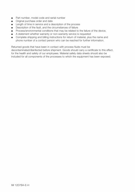
Part number, model code and serial number Original purchase order and date Length of time in service and a description of the process Description of the fault, and the circumstances of failure Process/environmental conditions that may be related to the failure of the device. A statement whether warranty or non-warranty service is requested Complete shipping and billing instructions for return of material, plus the name and
phone number of a contact person who can be reached for further information.
Returned goods that have been in contact with process fluids must bedecontaminated/disinfected before shipment. Goods should carry a certificate to this effect,for the health and safety of our employees. Material safety data sheets should also beincluded for all components of the processes to which the equipment has been exposed.
IM 12D7B4-E-H
1
1. INTRODUCTION AND GENERAL DESCRIPTIONThe Yokogawa EXAxt SC150 is a 4-wire panel mounted converter designed for industrialprocess monitoring, measurement and control applications. This instruction manual containsthe information needed to install, set up, operate and maintain the unit correctly. Thismanual also includes a basic troubleshooting guide to answer typical user questions.
Yokogawa can not be responsible for the performance of the EXAxt analyzer if theseinstructions are not followed.
1-1. Instrument checkUpon delivery, unpack the instrument carefully and inspect it to ensure that it was notdamaged during shipment. If damage is found, retain the original packing materials(including the outer box) and then immediately notify the carrier and the relevant Yokogawasales office.
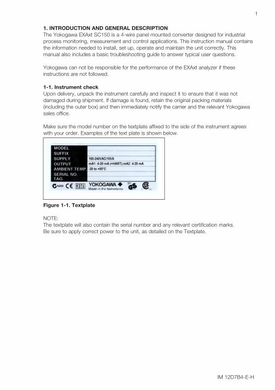
Make sure the model number on the textplate affixed to the side of the instrument agreeswith your order. Examples of the text plate is shown below.
Figure 1-1. Textplate
NOTE: The textplate will also contain the serial number and any relevant certification marks.Be sure to apply correct power to the unit, as detailed on the Textplate.

IM 12D7B4-E-H
2
1-2. ApplicationThe EXAxt converter is intended to be used for continuous on-line measurement ofconductivity or resistivity in industrial installations. The unit combines simple operation andmicroprocessor-based performance with advanced self-diagnostics and enhancedcommunications capability to meet the most advanced requirements. The measurement canbe used as part of an automated process control system. It can also be used to indicateoperating limits of a process, to monitor product quality, or to function as a controller for adosing/neutralisation system.
Yokogawa designed the EXAxt analyser to withstand industrial environments. The contoller may only be installed in a panel mounted configuration. The front panel forms an IP65 water tight seal against the flat face of the panel. Integralmounting clamps can be operated from the front of the panel. Sensors should normally be mounted close to the converter in order to ensure easycalibration and peak performance. If the unit must be mounted remotely from the sensors,WF10 extension cable can be used, up to a maximum of 50 meters (150 feet), with a BA10junction box, and up 10 meters standard sensor cable.
The EXAxt is delivered with a general purpose default setting for programmable items (seeChapter 5). While this initial configuration allows easy start-up, the configuration should beadjusted to suit each particular application. An example of an adjustable item is the type oftemperature sensor used. The EXAxt can be adjusted for a number of different types oftemperature sensors.
Details provided in this instruction manual are sufficient to operate the EXAxt with allYokogawa sensor systems and a wide range of third-party commercially available probes.For best results, read this manual in conjunction with the corresponding sensor instructionmanual.
Yokogawa designed and built the EXAxt to meet the CE regulatory standards. The unitmeets or exceeds stringent requirements (see section 2) without compromise, to assure theuser of continued accurate performance in even the most demanding industrial installations.
IM 12D7B4-E-H
3
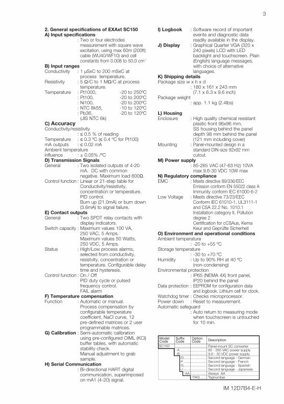
ModelCode
SuffixCode
OptionCode Description
Panel mount SC converter85 - 265 VAC power supply9.6 - 30 VDC power supplySecond language - GermanSecond language - FrenchSecond language - Spanish
Always AATagnumber
SC150-A-B -D -F -S
-AA/TAG
Second language - Japanese-J
2. General specifications of EXAxt SC150A) Input specifications
: Two or four electrodesmeasurement with square waveexcitation, using max 60m (200ft)cable (WU40/WF10) and cellconstants from 0.008 to 50.0 cm-1
B) Input rangesConductivity : 1 µSxC to 200 mSxC at
process temperature.Resistivity : 5 Ω/C to 1 MΩ/C at process
temperature.Temperature : Pt1000, -20 to 250ºC
: Pt100, -20 to 200ºC: Ni100, -20 to 200ºC: NTC 8k55, -10 to 120ºC: Pb36, -20 to 120ºC
(JIS NTC 6k)C) AccuracyConductivity/resistivity
: ≤ 0.5 % of readingTemperature : ≤ 0.3 ºC (≤ 0.4 ºC for Pt100)mA outputs : ≤ 0.02 mA Ambient temperature influence : ± 0.05% /ºCD) Transmission SignalsGeneral : Two isolated outputs of 4-20
mA. DC with commonnegative. Maximum load 600Ω.
Control function : Linear or 21-step table forConductivity/resistivity,concentration or temperature.PID control.Burn up (21.0mA) or burn down(3.6mA) to signal failure.
E) Contact outputsGeneral : Two SPDT relay contacts with
display indicators.Switch capacity : Maximum values 100 VA,
250 VAC, 5 Amps.Maximum values 50 Watts,250 VDC, 5 Amps.
Status : High/Low process alarms,selected from conductivity,resistvity, concentration ortemperature. Configurable delaytime and hysteresis.
Control function : On / OffPID duty cycle or pulsedfrequency control.FAIL alarm
F) Temperature compensationFunction : Automatic or manual.
Process compensation byconfigurable temperaturecoefficient, NaCl curve, 12 pre-defined matrices or 2 userprogrammable matrices.
G) Calibration : Semi-automatic calibrationusing pre-configured OIML (KCl)buffer tables, with automaticstability check.Manual adjustment to grabsample.
H) Serial Communication: Bi-directional HART digital
communication, superimposedon mA1 (4-20) signal.
I) Logbook : Software record of importantevents and diagnostic datareadily available in the display.
J) Display : Graphical Quarter VGA (320 x240 pixels) LCD with LEDbacklight and touchscreen. Plain(English) language messages,with choice of alternativelanguages.
K) Shipping detailsPackage size w x h x d
: 180 x 161 x 243 mm (7.1 x 6.3 x 9.6 inch)
Package weight : app. 1.1 kg (2.4lbs)
L) HousingEnclosure : High quality chemical resistant
plastic front 96x96 mm. SS housing behind the paneldepth 98 mm behind the panel(121 mm including cover)
Mounting : Panel-mounted design in astandard DIN-size 92x92 mmcutout.
M) Power supply: 85-265 VAC (47-63 Hz) 10VA
max 9.6-30 VDC 10W maxN) Regulatory complianceEMC : Meets directive 89/336/EEC
Emission conform EN 55022 class A Immunity conform IEC 61000-6-2
Low Voltage : Meets directive 73/23/EECConform IEC 61010-1, UL3111-1and CSA 22.2 No. 1010.1Installation category II, Pollutiondegree 2Certification for cCSAus, KemaKeur and Geprüfte Sicherheit
O) Environment and operational conditionsAmbient temperature
: -20 to +55 ºCStorage temperature
: -30 to +70 ºCHumidity : Up to 90% RH at 40 ºC
(non-condensing)Environmental protection
: IP65 (NEMA 4X) front panel,IP20 behind the panel
Data protection : EEPROM for configuration dataand logbook. Lithium cell for clock.
Watchdog timer : Checks microprocessor.Power down : Reset to measurement.Automatic safeguard
: Auto return to measuring modewhen touchscreen is untouchedfor 10 min.

IM 12D7B4-E-H
4
3. INSTALLATION AND WIRING
3-1. Installation siteThe EXAxt converter should be installed as close as possible to the sensor to avoid longcable runs between sensor and converter. In any case, the cable length should not exceed60 meters (200 feet). Select an installation site where:
Mechanical vibrations and shocks are negligible No relay/power switches are in the direct environment Access is possible rear of the unit for wiring The transmitter is not mounted in direct sunlight or severe weather conditions Maintenance procedures are possible (avoiding corrosive environments)
The ambient temperature and humidity of the installation environment must be within thelimits of the instrument specifications. (See chapter 2).
3-2. Mounting and dimensions Refer to fig. 3-1 to 3-5. Note that the EXAxt has integrated mounting clamps:The EXAxt uses an Integral mounting clamp at each corner, driven by screws operated fromthe front panel, fig. 3-1. Ensure that the clamp “fingers” are backed off a few millimeters more than the thickness
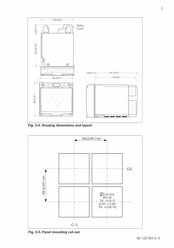
of the panel, fig. 3-2. Insert the unit through the mounting hole (Square hole, 92 x 92 tol.+0.5/-0mm), fig. 3-3-1. Rotate the unit slightly anti-clockwise to allow the clamp fingers to pass through the panel. Rotate the unit clockwise slightly (back to square) and tighten the 4 screws to hold it in
place, fig. 3-3-2 and fig. 3-3-3. Tighten the screws progressively to ensure that the panel seal seats evenly, fig. 3-3-4.
Fig. 3-1. Integrated mounting clamps Fig. 3-2. Clamp Finger
FINGER
PANEL THICKNESS11 to 18 mm
FINGER
PANEL THICKNESS0 to 11 mm
1
2
2 31 4
Fig. 3-3. Insertion of the Unit through a mounting hole
IM 12D7B4-E-H
5
Fig. 3-5. Panel mounting cut-out
Fig. 3-4. Housing dimensions and layout
C/L
C / L
100 (3.94") min
Cut-Out92x 92
Tol. +0,5/-0 (3.63" x 3.63"Tol. +0.02/-0)
100
(3.9
4") m
in
96 (3.8")
96
(3
.8")
25 (1
")
90 (3.54")
95.5
(3.7
6")
Safety Cover
118 (4.6")
25 (1") 121 (4.75")

IM 12D7B4-E-H
6
3-3. PreparationThe power/output connections and the sensor connections should be made in accordancewith the scheme shown in Figure 3-6. The terminals are of a plug in style for ease of wiring.
3-4. Cables, terminals and safety coverThe EXAxt 150 is equipped with terminals suitable for the connection of finished cables inthe size range: 0.13 to 2.5 mm2 (26 to 14 AWG). Forked or pin crimps can be used toterminate the cables.
Safety Note:When the wiring of the power/contact connections has been completed the clear safetycover should be clipped into place.
Figure 3-6. Rear view showing connection
Caution - Risk of electric shock
See section 3.7 and 3.8 for correct wiring

IM 12D7B4-E-H
7
4-20 mA
HAND HELD
OUTPUTSIGNALS
mA1
mA2
S1
S2
CONTACTOUTPUT
SENSOR
POWER9.6 to 30 VDC, 10W max85 to 265 VAC, 10VA max
INPUT CONTACT
Figure 3-7. System configuration
3-5. Wiring the power supplyMake sure the power supply is switched off. Also, make sure that the power supply iscorrect for the specifications of the EXAxt and that the supply agrees with the voltagespecified on the textplate.Local health and safety regulations may require an external circuit breaker to be installed.The instrument is protected internally by a fuse soldered to the printed circuit board. The fuse rating is dependent on the supply to the instrument.
Fuse ratings are:For the DC version 1 AFor the AC version 125 mA250 Volt, Time-lag T, IEC60127
3-6.Wiring the Relay Contacts Connect the relay contacts having regard to the use to which the relays are put. Thevoltage and current being switched should determine the type of wire used. Because therelays may be used to switch higher voltages, there is a cover for the terminal block (andmains supply terminals) that should be clipped in place when the wiring is completed. This isto prevent electric shock to unwary personnel.
Action
Power OFF
Power ONAlarm OFF
Power ONAlarm ON
S1, S2 FAIL
NC
NC
NO
NC
NC
NO
common
NC
NO
LED
3-8. Normally open and normally closed

IM 12D7B4-E-H
8
Connection Diagram
High Voltage Signals
mA OutputsPowerSupply
RelayContacts Sensor Input
Contact Input
POWER SUPPLY OUTPUTS
100-240VAC/10VA
CONTACTS
INPUTS
SEE MANUAL
NC
C
NO
NC
C
NO
S1
S2
240V/5A AC/DC
Temp
mA1
mA2
Shield
HIGH VOLTAGE
L
N
1
2
3
41
42
43
+-
11
12
13
14
15
16
21
22
+-
+-
61
62
65
66
63
100VA/50W
31
32
33
Figure 3-9. General connections Conductivity and Resistivity measurement
3-7. Wiring the Current Outputs
The current outputs should be connected using twisted pair signal cable. The screen(shield) should be connected to ground (at one end only).
Note: The HART signal is super imposed on mA 1. When using this signal, attention shouldbe paid to the load resistance. In some cases a separate load resistor will be needed,across which the HART signal can be read. In this case a 250 Ohm resistor should beused.
Caution - Risk of electric shock
See section 3.7 and 3.8 for correct wiring

IM 12D7B4-E-H
9
15
16
14
14
17
13
12
WF10 Extension Cable
BA10 Connection Box
11
15
16
14
14
17
13
12
11
11 TEMPERATURE
12 TEMPERATURE
13 INNER ELECTRODE
14 OUTER ELECTRODE
15 INNER ELECTRODE
16 OUTER ELECTRODE
1
2
12
SX42-SX . . - . F SENSORS
BROWN
YELLOW / GREENRED
11 TEMPERATURE
12 TEMPERATURE
13 1 INNER CELL
14 1 OUTER CELL
15 2 INNER CELL
16 2 OUTER CELL
CONDUCTIVITY / RESISTIVITY TRANSMITTER
nd
st
st
nd
Fig. 3-10. Sensor wiring diagrams
3-8. Wiring of sensors
General precautionsGenerally, signals from sensors are at low voltage and current level. Thus a lot of care mustbe taken to avoid interference. Before connecting sensor cables to the transmitter makesure that following conditions are met: – the sensor cables are not mounted in tracks together with high voltage and or power
switching cables– only standard sensor cable or extension cable is used– the transmitter is mounted within the distance of the sensor cables (max. 10 m) + up to
50m WF10 extension cable.– the setup is kept flexible at the sensors end for easy insertion and retraction of the
sensor in the fitting.
Sensor wiringRefer to figure 3-10, which includes drawings that outline sensor wiring.The EXAxt can be used with a wide range of sensor types. The sensor system fall into twocategories, the ones that use fixed cables and the ones with separate cables.To connect sensors with fixed cables, simply match the terminal numbers in the instrumentwith the identification numbers on the cable ends.

IM 12D7B4-E-H
10
4. OPERATION OF EXAxt SC150
4-1. Main display functions
4-2. Trending graphics.
Pressing the button changes the displayinto a graphical mode in which the averagemeasured value is shown on a time scale.The “Live” value is also digitally displayed ina text box. The time scale ( X-axis) and theprimary value scale (Y-axis) are set in the"DISPLAY SETUP" menu. The full screendisplays a trend of 51 points that representthe average of the selected time interval.The analyzer samples the measurementevery second. The trending graphic alsoshows the maximum and minimummeasured value in the that interval. For example if the time scale is set to 4hours, then the trend is shown for 4 hoursprior to the actual measurement. Each pointon the trend line represents the averageover 4*60*60/51= 282 measurements(seconds).
4-3. Zoom in on details
This button gives access to the diagnosticinformation of the analyzer. The followingmessages will appear under normal(default) conditions:
Zoom in on Details
4-3-1. CC (factory) = the nominal cellconstant as determined by the factorycalibration during production. This value isset during commissioning, and is found onthe nameplate of the sensor or thecalibration certificate.Routing: Commissioning >>Routing: Commissioning >>Measurement setup >> ConfigureMeasurement setup >> Configuresensorsensor
4-3-2. CC(adjusted) = the calibrated cellconstant. When the calibration of thesystem is adjusted on-line by grab sampleor by calibrated solution technique, thenew cell constant is recorded here. Thisvalue should not deviate greatly from theoriginal factory calibration. In the event thatthere is a significant discrepancy seenbetween this reading and the CC (factory)value, the sensor should be checked fordamage and cleanliness.Routing is via the "Calibration" menu.
4-3-3. Temp. comp 1 = the chosentemperature compensation method for theprimary measurement.Routing: Commissioning >>Routing: Commissioning >>Measurement setup >>Measurement setup >>Temp.compensationTemp.compensation
-Go to graph screen
Ma n Screen
-Go to detail screen
-Go to info screen
-Go to setup screen
S/cm -Home key back CC (factory) 0.100/cmCC (adjusted) 0.100/cmTemp. comp 1 NaClTemp. comp 2 NoneActual mA1 4.00Actual mA2 4.00
-Up one level
to mainscreen
-Move down cursor
-Enter selected submenu
Max
imum
Min
imum
Minimum
Maximum
Average
Live
read
ing
SC
SC
T
120.0
90.0
60.0
30.0 109.3 S/cm
Fig 4-2. Trend Screen
Fig 4-1. Main Display
Fig 4-3. Detail Screen

IM 12D7B4-E-H
11
4-3-4. Temp. comp 2 = the chosentemperature compensation method for thesecondary measurement.Note: This does not imply two separatemeasurements. There is the possibility toset two separate compensation methodsso that two different stages of the sameprocess can be monitored accurately. Anexample is process/cleaning fluid interface.Routing: Commissioning >>Routing: Commissioning >>Measurement setup >>Measurement setup >>Temp.compensationTemp.compensation
4-3-5. actual mA1 = the current output inmA of the first current output, which isdefined as mA1. The range and function ofthis mA output can be set in: Routing: Commissioning >> Outputsetup >> mA1
4-3-6. actual mA2 = the current output inmA of the second current output, which isdefined as mA2. The range and function ofthis mA output can be set in:Routing: Commissioning >> OutputRouting: Commissioning >> Outputsetup >> mA2setup >> mA2
4-3-7. Lasst calibrated at = the date ofthe last calibration
4-3-8. Calibration due at = the datescheduled for the next calibration. This fieldis determined by the calibration interval.Routing: Commissioning >>Routing: Commissioning >>Measurement setup >> CalibrationMeasurement setup >> Calibrationsettingssettings
4-3-9. Projected calibration at = adiagnostic output, showing the date whenthe unit should next be maintainedaccording to the sophisticated self-diagnostic tools built into the EXAxtsoftware. The analyzer checks the rate ofpolarization every 24 hours. If a clearincrease of polarization is observed, theuser is notified when a next calibrationshould take place. Prior to calibration thesensor should be well cleaned and rinsed.
4-3-10. Polarization perc. = the %polarization measured by the inputcircuitry. Monitoring this figure gives aguide to progressive fouling of the sensor.
4-3-11. Sensor Ohms = the inputmeasurement as an uncompensatedresistance value.
4-3-12. Device ID = serial number of theanalyzer.
4-3-13. Software revision = the revisionlevel of the software in the instrument.
4-3-14. DD revision = the HART devicerevision
TROUBLE SHOOTINGIf you contact the local sales/ serviceorganization the ID and software revisioninformation is necessary information.Without that information it is impossible tohelp you. It is also very useful to report allthe information that you find on the zoom-in display.
IM 12D7B4-E-H
12
2x to
down
for
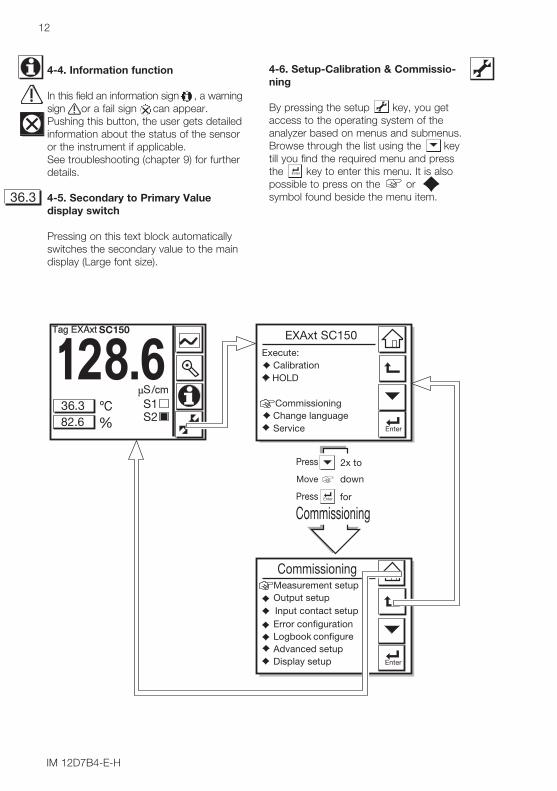
4-6. Setup-Calibration & Commissio-ning
By pressing the setup key, you getaccess to the operating system of theanalyzer based on menus and submenus.Browse through the list using the keytill you find the required menu and pressthe key to enter this menu. It is alsopossible to press on the orsymbol found beside the menu item.
4-4. Information function
In this field an information sign , a warningsign or a fail sign can appear.Pushing this button, the user gets detailedinformation about the status of the sensoror the instrument if applicable.See troubleshooting (chapter 9) for furtherdetails.
4-5. Secondary to Primary Valuedisplay switch
Pressing on this text block automaticallyswitches the secondary value to the maindisplay (Large font size).
IM 12D7B4-E-H
13
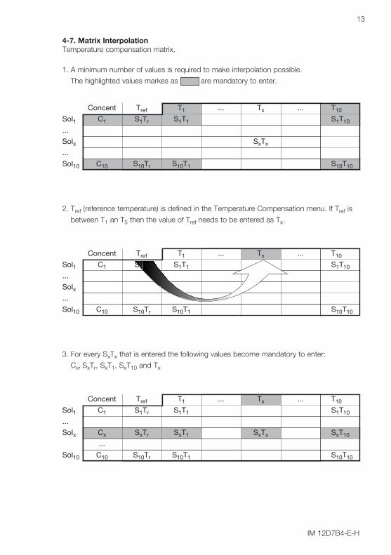
4-7. Matrix InterpolationTemperature compensation matrix.
1. A minimum number of values is required to make interpolation possible.
The highlighted values markes as are mandatory to enter.
Concent Tref T1 ... Tx ... T10
Sol1 C1 S1Tr S1T1 S1T10
...
Solx SxTx
...
Sol10 C10 S10Tr S10T1 S10T10
2. Tref (reference temperature) is defined in the Temperature Compensation menu. If Tref is
between T1 an T5 then the value of Tref needs to be entered as Tx.
Concent Tref T1 ... Tx ... T10
Sol1 C1 S1Tr S1T1 S1T10
...
Solx...
Sol10 C10 S10Tr S10T1 S10T10
3. For every SxTx that is entered the following values become mandatory to enter:
Cx, SxTr, SxT1, SxT10 and Tx
Concent Tref T1 ... Tx ... T10
Sol1 C1 S1Tr S1T1 S1T10
...
Solx Cx SxTr SxT1 SxTx SxT10
...
Sol10 C10 S10Tr S10T1 S10T10

IM 12D7B4-E-H
14
IM 12D7B4-E-H
15
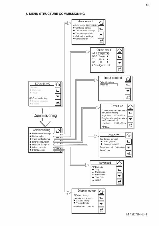
5. MENU STRUCTURE COMMISSIONING

IM 12D7B4-E-H
16
Measurement SetupMain parameterChoose the required parameter, eitherconductivity or resistivity. If the mainparameter is changed the instrument willreset main display settings, units andrecalculate several values. The menustructure will change accordingly.
5-1. Configure sensor Sensor typeChoose the sensor type used. Normallyconductivity and/or resistivitymeasurements are done with 2-electrodetype sensors. At high conductivity ranges,polarisation of the electrodes may causean error in conductivity measurement. Forthis reason 4-electrode type sensors maybe necessary.
Measuring unit /cm /mEither /cm or /m can be chosen here. TheProcess values will be expressed in S/cmor S/m respectively, (Ω.cm or Ω.m inResistivity mode).
Cell constant (factory)Cell constant given by factory calibration.Usually given on a label on the sensor orthe calibration certificate.
MeasureProcess values to be measured can beselected to suit the user’s preference.:Conductivity only, Concentration only or oneof both Conductivity and Concentration.Note: this choice is not available inResistivity mode.
5-2. Temperature SettingTemperature ElementSelection of the temperature sensor usedfor compensation. The default selection isthe Pt1000 Ohm sensor, which givesexcellent precision with the two wireconnections used. The other options givethe flexibility to use a very wide range ofother conductivity/resistivity sensors.
Temperature UnitCelcius or Fahrenheit temperature scalescan be selected to suit the user’spreference.
5-3. Temperature CompensationCompensationTwo types of methods can be used here.Automatic for use of temperature element.Select one of the Temperature elementsused. The other is a manual settemperature. The manual temperature thatrepresents the process temperature mustbe set here.
Reference TemperatureChoose a temperature to which themeasured conductivity (or resistivity) valuemust be compensated. Normally 25°C(77ºC) is used, therefore this temperatureis chosen as default value.
MethodTC In addition to the temperaturecoefficient calibration routine it is possibleto adjust the compensation factor directly.If the compensation factor of the sampleliquid is known from laboratory experimentsor has been previously determined, it canbe introduced here.Adjust the value between 0.00 to 3.50 %per °C. In combination with referencetemperature a linear compensationfunction is obtained, suitable for all kinds ofchemical solutions.NaCl Temperature compensationaccording NaCl curve. See appendix 1 forvalues.Matrix The EXAxt is equipped with amatrix type algorithm for accuratetemperature compensation in variousapplications. Select the range as close aspossible to the actualtemperature/concentration range. TheEXAxt will compensate by interpolation. Ifuser defined 1 or user defined 2 isselected, the temperature compensationrange for the adjustable matrix must bedefined. See section 4-7 for matrix interpolation.
Note!Extra information on temperaturecompensation is given in appendix 1.

IM 12D7B4-E-H
17
This selection will influencea number of choices anddefaults throughout thewhole menu.
In the selection boxesdefaults are shownwith a black background.
Generally defaults areshown with their rangesand possible choices.
IM 12D7B4-E-H
18
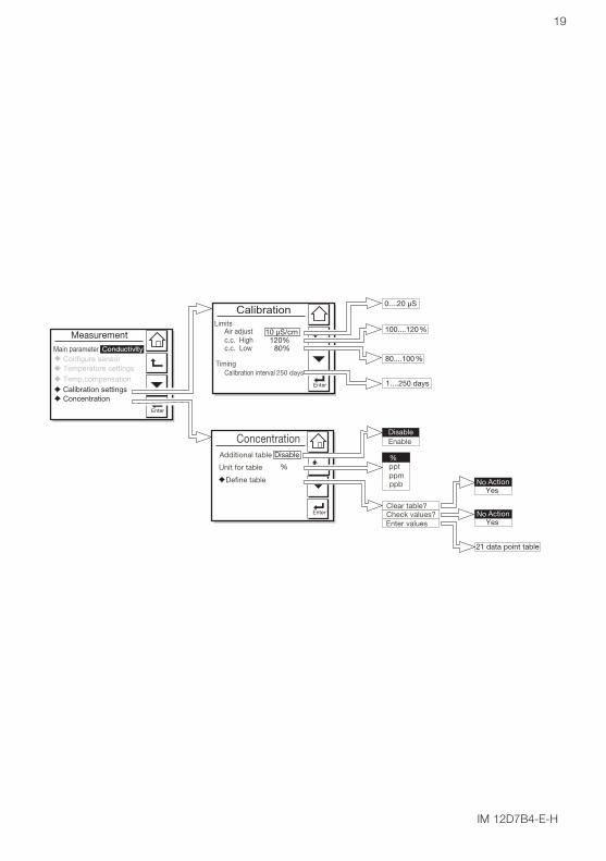
5-4. Calibration SettingsAir adjust limitTo avoid cable influences on themeasurement, a "zero" calibration with adry sensor may be done. If a connectionbox (BA10) and extension cable (WF10) arebe used, "zero" calibration should be doneincluding this connection equipment. When using a 4-electrode sensor additionalconnections are required. TemporarilyInterconnect terminals 13 & 14 with eachother and 15 & 16 with each other beforemaking the adjustment. This is necessaryto eliminate the capacitive influence of thecables. The links should be removed afterthis step is completed. As the calibration is performed in air theresistivity is infinite (open connection).Lower values than the air adjust limitindicate the cell is not in air or is still wet.To prevent wrong air calibrations a limitmust be given here.
c.c. high limitHigh limit of the cell constant expressed in% of nominal value. During calibration thisvalue is used to check if the calibrated cellconstant remains within reasonable limits.
c.c. low limitLow limit of the cell constant expressed in% of nominal value. During calibration thisvalue is used to check if the calibrated cellconstant remains within reasonable limits.
Calibration IntervalA user defined interval in which a newcalibration should take place. If the intervalis exceeded the instrument will give awarning or a fail (user definable in errorconfiguration 2/3)
5-5. ConcentrationThere are two ways to come to aconcentration value. 1. use a matrix for temperaturecompensation, which includesconcentration values. See section 5-3.Commissioning>> MeasurementCommissioning>> Measurementsetup>> Temp.compensation>>setup>> Temp.compensation>>MethodMethod2. use the additional concentration table,which can be combined with any of thetemperature compensation methods.Additional tableThis 21x2 user defined concentration tableis used to come to more accurateconcentration values compared to thetemperature compensation matrix.Enabling this additional table overrules theconcentration values obtained from thematrix (if used).
Unit for tableThe way the concentration values arepresented to the user. Changing the unitwill not result in a re-calculation of thetable.
21 data point table
In the selection boxesdefaults are shownwith a black background.
Generally defaults areshown with their rangesand possible choices.
IM 12D7B4-E-H
19
IM 12D7B4-E-H
20
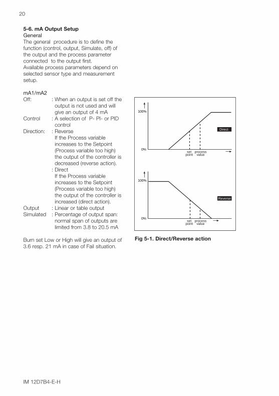
5-6. mA Output SetupGeneralThe general procedure is to define thefunction (control, output, Simulate, off) ofthe output and the process parameterconnected to the output first.Available process parameters depend onselected sensor type and measurementsetup.
mA1/mA2Off: : When an output is set off the
output is not used and willgive an output of 4 mA
Control : A selection of P- PI- or PID control
Direction: : ReverseIf the Process variableincreases to the Setpoint(Process variable too high)the output of the controller isdecreased (reverse action).
: DirectIf the Process variableincreases to the Setpoint(Process variable too high)the output of the controller isincreased (direct action).
Output : Linear or table outputSimulated : Percentage of output span:
normal span of outputs are limited from 3.8 to 20.5 mA
Burn set Low or High will give an output of3.6 resp. 21 mA in case of Fail situation.
100%
0%set
pointprocess
value
Direct
100%
0%set
pointprocess
value
Reverse
Fig 5-1. Direct/Reverse action

IM 12D7B4-E-H
21
0.000100.0
Note: default settings relateto conductivity, comparabledefaults exist for resistivity

IM 12D7B4-E-H
22
5-7. Contact Output SetputS1/S2Each Switch (contact) has 4 functions.When a Switch is set to off the Switch isnot used.
Control: A selection of P- PI- or PID control
Alarm: Low or high value Limits monitoring
Hold: A Hold contact is energized whenthe instrument is in HOLD
Fail: A Fail contact is energized whena fail situation occurs. Fail situations are configured insection 5-9. For SOFT Fails thecontact and the display LED arepulsating. For HARD Fails thecontact and the display LED areenergized continuously.
The contact reacts to Hard FailsOnly
The contact reacts to Hard andSoft Fails
Simulate: The contact can be switched on/off or a percentage of output can be simulated. This percentageis a analogue value and representsthe on time per second.
5-8. Configure HoldGeneralHold is the procedure to set the outputs toa known state when going into commissio-ning. During commissioning HOLD isalways enabled, outputs will have a fixed orlast value. During calibration the sameHOLD function applies. For calibration, it isup to the user if HOLD is enabled or not.
Note! When leaving Commissioning, Holdremains active until switched off manually.This is to avoid inappropriate actions whilesetting up the measurement
Fig. 5-3. Duty cycle control
Fig. 5-4. Pulse frequency control
t (sec)
LED off
Hys.
Setpoint
LED on
Delay time Delay time
LED off
SC
Fig. 5-2. Alarm contact
100
50
0
0.3 s
90% 10%
100
50
0
ont toff
90%10%
50% 50%
% of output range
% duty cycle control
SetpointProportional
range Time
Duty cycleSC
SC
% of output rangeSetpointProportional
range Time
Maximum pulse frequency
50 % pulse frequency
No pulses
% controller output
Hard Fail Only
Hard + Soft Fail

IM 12D7B4-E-H
23
Note: default settings relateto conductivity, comparabledefaults exist for resistivity
alarm
A Soft Fail enables the fail contact pulseA Soft Fail is shown on the display only
24
5-9. Input Contact SetupGeneralRemote range switching to 10 times theprogrammed range.
Factor 10 mA1 and/or mA2This "ZOOM" function will cause the rangeof the mA to be multiplied by 10 when thebinary input is closed. The range is dividedby 10 when the binary contact is opened.
5-10. Error ConfigurationErrors 1/3 ~ 3/3Error message configuration. Two differenttypes of failure mode can be set.
Hard fail gives a steady FAIL flag in thedisplay, and a continuous contact closure.All the other contacts (controls) areinhibited and a Fail signal is transmitted onthe outputs when enabled.
Soft fail gives a flashing FAIL flag in thedisplay, and the relay contact is pulsed.The other contact (controls) is stillfunctional, and the controller continues towork normally. A good example is a controltime-out for a soft fail. A warning that theregular maintenance is due, should not beused to shut down the wholemeasurement.
5-11. Logbook ConfigurationGeneralLogbook is available to keep an electronicrecord of events such as error messages,calibrations and programmed datachanges. By reference to this log, userscan for instance easily determinemaintenance or replacement schedules.
In configure Logbook the user can selecteach item he is interested in to be loggedwhen the event occurs. This can be donefor three separate logbooks. Each logbookcan be erased individual.
IM 12D7B4-E-H

25
Note: The choices above onlyappear when linear conductivityis chosen on output 1 and/or 2.
Select functions:
IM 12D7B4-E-H
IM 12D7B4-E-H
26
5-12. Advanced setup
DefaultsThe functionality of the EXAxt allows tosave and load defaults to come to a knowninstrument setting. The EXAxt has bothfactory and user defined defaults.After a “load default” the instrument willreset. The following parameters are not includedin a reset:
1. X-axis timing2. Auto return (10 min / disabled)3. Tag4. passwords5. date and time6. language7. the contents of all logbooks8. HART parameters (address, tag,
descriptor, message)
TagA tag provides a symbolic reference to theinstrument and is defined to be uniquethroughout the control system at one plantsite.
PasswordsCalibration and Commissioning may beseparately protected by a password.Default both passwords are empty.Entering an empty password results indisabling the password check.A password can contain up to 8characters.
Date/timeThe Logbooks and trend graph use theclock/calendar as reference. The currentdate and time is set here. The current timeis displayed in the “zoom” menu.
Note! The fixed format is YYYY/MM/DDHH:MM:SS
Test QICThis menu enables the customer toexecute the Quality Inspection test asdescribed in the QIS (attached in this IM).
HARTThe address of the EXAxt in a HARTnetwork can be set. Valid addresses are0...15.

IM 12D7B4-E-H
27
No action
After the defaults are loaded, the instrument will reset
Load factory defaultsSave current as user definedLoad user defined defaults
No action

IM 12D7B4-E-H
28
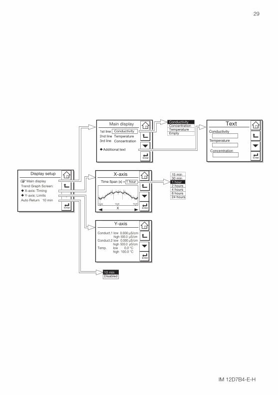
5-13. Display SetupMain DisplayThe main display consists of three lineswith Process Values. Each line is userdefinable with the restriction that each lineshould have a different Process Value. Thedefault settings can be defined here. Bypressing one of the two smaller processvalues, this will become the main processvalue in the main screen. Autoreturn willcause the main display to go to defaultsetting.See also 4.5 Secondary to Primary Valuedisplay Switch.
Note! Configuration possibilities in the mainand secondary display lines are determinedby the choices made in the menu items 8 Measurement setup >> MainMeasurement setup >> Mainparameter andparameter and >> Measurement>> Measurementsetup >> Configure sensorsetup >> Configure sensor
Additional textEach process value can be given anadditional text containing up to 12characters per text. This text is displayedon the main display next to the processvalue. This way the user can distinguishseparate Conductivity/Concentrationmeasurements.
X-axis TimingThe time range of the trend graph can beset from 15 minutes up to 1 day.
Y-axis LimitsThe ranges for each measurement need tobe set according the application.
Auto ReturnWhen Auto return is enabled, the converterreverts to the measuring mode (maindisplay) from anywhere in the configurationmenus, when no button is pressed duringthe set time interval of 10 minutes.
IM 12D7B4-E-H
29
Time Span (x) = 1 hour
Temperature
Concentration
IM 12D7B4-E-H
30
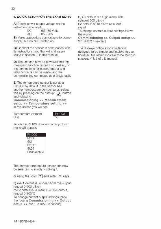
G) S1 default is a High alarm with setpoint 500 µS/cm S2 default is Fail alarm as a fault signalTo change contact output settings followthe routing Commissioning >> Output setup >>Commissioning >> Output setup >>S 1 (& S 2 if needed).
The display/configuration interface isdesigned to be simple and intuitive to use,however, full instructions are to be found insections 4 & 5 of this manual.
6. QUICK SETUP FOR THE EXAxt SC150
A) Check power supply voltage on theinstrument side label
DC 9.6 -30 VoltsAC 85 - 265
B) Make appropriate connections to powersupply, but do NOT switch on.
C) Connect the sensor in accordance withits instructions, and the wiring diagramfound in section 3, in this manual.
D) The unit can now be powered and themeasuring function tested if so desired, orthe connections for current output andrelay contacts can be made, and thecommissioning completed as a single task.
E) The temperature sensor is set as aPT1000 by default. If the sensor hasanother temperature compensator, selectthis by pressing on the “Setup” buttonand followingCommissioning >> MeasurementCommissioning >> Measurementsetup >> Temperature setting >> setup >> Temperature setting >> In this screen you will see
Temperature element Pt1000Unit °C
Touch the PT1000 box and a drop downmenu will appear.
Pt1000Pt1005k1Ni1008k55Pb36(JI56K)
The correct temperature sensor can nowbe selected by simply touching it,
or using the scroll and enter keys.
F) mA 1 default is a linear 4-20 mA output,ranged 0-500 µS/cmmA 2 default is a linear 4-20 mA output,ranged 0-100°CTo change current output settings followthe routing Commissioning >> OutputCommissioning >> Outputsetup >>setup >> mA 1 (& mA 2 if needed).

IM 12D7B4-E-H
31
7. CALIBRATION
7-1 GeneralThe calibration (cell constant) of a conductivitysensor is determined at the constructionstage, because it is a factor set by the sizeof the electrodes, and their distance apart.A conductivity sensor does not change itscell constant during operation, as long as itremains undamaged, and clean. It istherefore vital that in any calibration checkthe first step should be to clean the sensor,or at least check its cleanliness. Aftercleaning ensure that the sensor is carefullyrinsed in distilled water to remove all tracesof the cleaning medium.
In the commissioning menu, the originalsensor configuration will include theprogramming of the cell constant definedfor the sensor at manufacture. Follow therouting below to the setup screen :Commissioning >> MeasurementCommissioning >> Measurementsetup >> Configure sensorsetup >> Configure sensor
The Calibration menu of the SC150 isprovided for fine tuning the sensor setup,and checking and verification after a time inservice.
Where 1st and 2nd compensations arereferred to in this part of the menu, theseprovide alternatives for the "wet"calibration, designed to give the user thegreatest flexibility.This does not mean that two cell constantscan or should be calibrated, they arealternative routes to the same end!
7-2. Cell constant manualThe intention of this calibration routine is tofine tune a sensor for which only thenominal cell constant is known, orrecalibrate a sensor that has been changed(or damaged) in the course of operation.Choose 1st or 2nd compensation to suitthe calibration solution used. The solutionshould be prepared or purchased, meetingthe highest standards of precisionavailable. Allow the sensor to reach stablereadings for both temperature andconductivity before adjusting to correspondto the calibration solution value.
The setting of a cell constant for a new(replacement) sensor is also possible in thisroutine. This avoids the need for entry intothe commissioning mode, which may haveanother authorization (password) level.
7-3. Cell constant automaticThis routine is built around the test methoddescribed in OIML (OrganisationInternationale de Metrologie Legale).International Recommendation No. 56. Itallows the direct use of the solutionsprescribed in the test method,automatically selecting the appropriatetemperature compensation. The look uptable is used to find the appropriateconductivity reading for the measuredtemperature. See appendix 2 for OIMLsolutions
7-4. Air (zero) calibration With the clean dry cell in open air, thereading should be zero. The Air calcompensates for excess cablecapacitance, and gives a better accuracyat low readings. This should be done forall installations during commissioning.After some time in service a dirty sensormay well show a high zero offset becauseof fouling. Clean the sensor and try again.
7-5. Sample calibrationWith the sensor in situ, a sample can betaken for laboratory analysis. Samplecalibration records the time and reading,and holds these in memory until theanalysis has been completed. Thelaboratory data can then be enteredregardless of the current process value,without the need for calculations.
IM 12D7B4-E-H
32
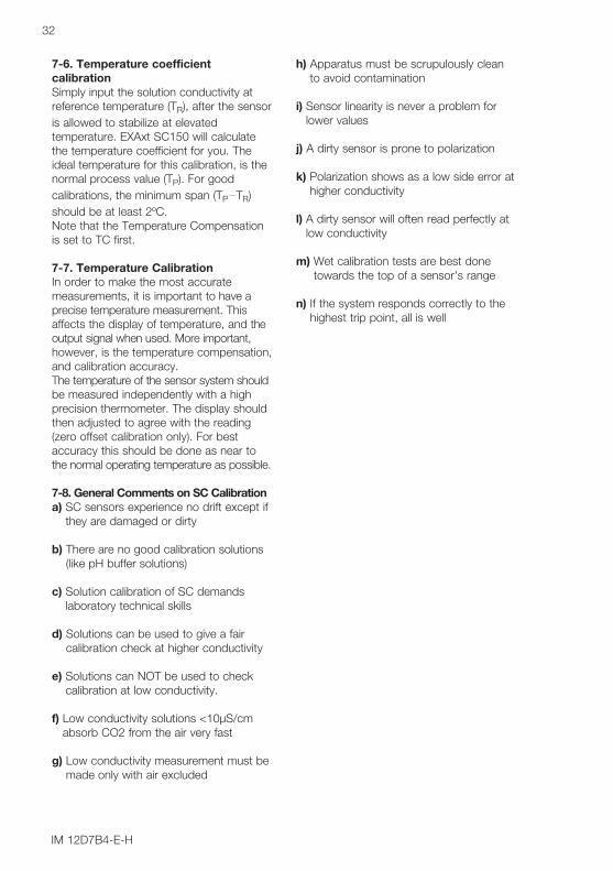
7-6. Temperature coefficientcalibrationSimply input the solution conductivity atreference temperature (TR), after the sensoris allowed to stabilize at elevatedtemperature. EXAxt SC150 will calculatethe temperature coefficient for you. Theideal temperature for this calibration, is thenormal process value (TP). For goodcalibrations, the minimum span (TP TR)should be at least 2ºC. Note that the Temperature Compensationis set to TC first.
7-7. Temperature Calibration In order to make the most accuratemeasurements, it is important to have aprecise temperature measurement. Thisaffects the display of temperature, and theoutput signal when used. More important,however, is the temperature compensation,and calibration accuracy.The temperature of the sensor system shouldbe measured independently with a highprecision thermometer. The display shouldthen adjusted to agree with the reading(zero offset calibration only). For bestaccuracy this should be done as near tothe normal operating temperature as possible.
7-8. General Comments on SC Calibrationa) SC sensors experience no drift except if
they are damaged or dirty
b) There are no good calibration solutions(like pH buffer solutions)
c) Solution calibration of SC demandslaboratory technical skills
d) Solutions can be used to give a faircalibration check at higher conductivity
e) Solutions can NOT be used to checkcalibration at low conductivity.
f) Low conductivity solutions <10µS/cmabsorb CO2 from the air very fast
g) Low conductivity measurement must bemade only with air excluded
h) Apparatus must be scrupulously cleanto avoid contamination
i) Sensor linearity is never a problem forlower values
j) A dirty sensor is prone to polarization
k) Polarization shows as a low side error athigher conductivity
l) A dirty sensor will often read perfectly atlow conductivity
m) Wet calibration tests are best donetowards the top of a sensor's range
n) If the system responds correctly to thehighest trip point, all is well
IM 12D7B4-E-H
33
8. MAINTENANCE
8-1. Periodic Maintenance DisplayThe front of the unit is sealed to IP65(NEMA 4X). In normal operation EXAxt willbe sealed to the flat panel front, with a builtin gasket. Behind the panel, the unit has anIP20 rating.The converter requires very little periodicmaintenance, except to make sure the frontwindow is kept clean in order to permit aclear view of the display and allow properoperation of the touchscreen. If the windowbecomes soiled, clean it using a soft dampcloth or soft tissue. To deal with morestubborn stains, a neutral detergent maybe used.
NOTES:Never use harsh chemicals or solvents. Inthe event that the window does becomeheavily stained or scratched, refer to theparts list (Chapter 9) for replacement partnumbers.
The nature of the EXAxt SC150 is that thepanel environment should protect the backof the instrument. Exposure of this part ofthe unit to moisture may result in problems.This is especially true because of the highimpedance sensors that the pHmeasurement uses. This should be bornein mind when working behind the panel.
Battery The EXAxt analyzer contains a logbookfeature that uses a clock to provide thetimings. The instrument contains a lithiumcell (battery) to support the clock functionwhen the power is switched off. The cellhas an expected working life of 10 years.Should this cell need to be replaced,contact your nearest Yokogawa servicecenter for spare parts and instructions.
Fuse There is a circuit board mounted fuseprotecting the instrument. If you suspectthat this needs to be replaced, contactyour nearest Yokogawa service center forspare parts and instructions
8-2. Periodic Maintenance of the SensorNOTE:Maintenance advice listed here isintentionally general in nature. Sensormaintenance is highly application specific.In general conductivity/resistivitymeasurements do not need much periodicmaintenance. If the EXAxt indicatesan error in the measurement or in thecalibration, some action may be needed(ref. chapter 9 troubleshooting).When a 2-electrode sensor has becomefouled an insulating layer may be formedon the surface of the electrodes andconsequently, an apparent increase in cellconstant may occur, giving a measuringerror.
This error is:2 x Rv/Rcel x 100 %where:Rv = the resistance of the fouling layerRcel = the cell resistance
NOTE:Resistance due to fouling or to polarizationdoes not effect the accuracy and operationof a 4-electrode conductivity measuringsystem. If an apparent increase in cellconstant occurs cleaning the cell willrestore accurate measurement.
8-3. Cleaning Methods1. For normal applications hot water withdomestic washing-up liquid added will beeffective.2. For lime, hydroxides, etc., a 5 ...10%solution of hydrochloric acid isrecommended.3. Organic contaminants (oils, fats, etc.)can be easily removed with acetone.4. For algae, bacteria or moulds, use asolution of domestic bleach (hypochlorite).
* Never use hydrochloric acid and bleachingliquid simultaneously. The release of thevery poisonous chlorine gas will result.

IM 12D7B4-E-H
34
9. TROUBLESHOOTING
9-1. General The EXAxt is a microprocessor-basedanalyzer that performs continuous self-diagnostics to verify that it is workingcorrectly. Error messages resulting fromfaults in the micro-processor systems itselfare monitored. Incorrect programming bythe user will also result in an error, explainedin a message, so that the fault can becorrected according to the limits set in theoperating structure. The EXAxt also checksthe sensor system to establish whether it isstill functioning properly.
In the main display screen is a "StatusInformation" button that will show
For information
For warning - a potential problem isdiagnosed, and the system should bechecked.
For FAIL, when the diagnostics haveconfirmed a problem, and the system mustbe checked.This button gives access to a status reportpage, where "The most applicable error"will be displayed. ("No errors" is displayedduring proper operation)
Explanation >> Description or errormessage and possible remedies
Advanced troubleshooting>> Error codescreen that is used in conjunction with theservice manual. This data will also beneeded in the event that you requestassistance from a Yokogawa servicedepartment.
What follows is a brief outline of the EXAxttroubleshooting procedures includingpossible causes and remedies.
9-2. Calibration checkThe EXAxt SC150 converter incorporates adiagnostic check of the adjusted cell constantvalue during calibration. If the adjusted valuestays within 80-120 % of the factory value, it isaccepted, otherwise, the unit generates anerror message, and the calibration is rejected.
9-3. Polarization checkThe EXAxt SC150 performs on-line monitoringto detect polarization. This is an early indicatorfor sensor fouling. The detection of polarizationin the measurement gives a warning of theonset of sensor coating, before significantmeasuring errors build up.
9-4. Predictive MaintenanceEXAxt has a unique prediction feature.Calibration, and polarization check data arestored in software data logbooks. This datais then used to calculate a prediction formaintenance purposes.
9-5. Prediction of cleaning neededThe date when the next maintenance isneeded is calculated from on-line polarizationchecks. The trend of polarization measurementson the sensor is used to calculate when totell the user when to clean the sensor.
9-6. Poor calibration techniqueWhen the calibration data is not consistentthis fact is used as a diagnostic tool. Thesignificance of this error message is torequire the user to improve his calibrationtechnique. Typical causes for this error areattempting to calibrate dirty sensors,calibration solution contamination and pooroperator technique.
9-7. Error displays and actionsAll errors are shown in the "Main Display"screen, however, the EXAxt makes adistinction between diagnostic findings.The error messages may be set to OFF,WARN or FAIL. For process conditionswhere a particular diagnostic may not beappropriate, the setting OFF is used. FAILgives a display indication only of that thesystem has a problem and inhibits the relaycontrol action, and can be set to trigger the"Burn" function. "Burn-up” or “Burn-down"drives the mA output signal to 21 mA or3.6 mA respectively.

IM 12D7B4-E-H
35
1
2
3
4
5
Table 10.1 Itemized parts listItem no Description Part No.1 Front cover kit. xx150 (cover, hinge(s) & label) K1547SA2 Terminal kit xx150 (power, input, output & relay contacts) K1547SB3 Terminal protect. cover. xx150 K1547SC4 Panel fixing set ( screws, clamps & washers, 4 each per set) K1547SD5 Panel seal K1547SE
Fig. 10-1. Exploded view
10. SPARE PARTS

Configure calculated Temperature Coefficient (TC).
Follow routing Commissioning>> Measurement setup>> Commissioning>> Measurement setup>> Temp.compensation>>Temp.compensation>> T.C.Enter the temperature coefficient calculated from the following formula:
A. Calculation of Temperature Coefficient Factor( With known conductivity at reference temperature)..
α = Temperature compensation factor in %/°CT = Measured temperature in °CKt = Conductivity at TTref = Reference temperature Kref = Conductivity at Tref
T Kt α T Kt α T Kt α0 0.54 1.8 60 1.76 2.2 130 3.34 2.210 0.72 1.9 70 1.99 2.2 140 3.56 2.220 0.90 2.0 80 2.22 2.2 150 3.79 2.225 1.0 --- 90 2.45 2.2 160 4.03 2.230 1.10 2.0 100 2.68 2.2 170 4.23 2.240 1.31 2.0 110 2.90 2.2 180 4.42 2.250 1.53 2.1 120 3.12 2.2 190 4.61 2.2
200 4.78 2.2
11-1. Appendix 1
Temperature compensationThe conductivity of a solution is very dependent on temperature. Typically for every 1 °Cchange in temperature the solution conductivity will change by approximately 2 %. Theeffect of temperature varies from one solution to another and is determined by severalfactors like solution composition, concentration and temperature range. A coefficient (α) isintroduced to express the amount of temperature influence in % change in conductivity/°C.In almost all applications this temperature influence must be compensated before theconductivity reading can be interpreted as an accurate measure of concentration or purity.
NaCl or standard temperature compensationFrom the factory the EXAxt is set with the default of a general temperature compensationfunction based on a Sodium Chloride (table salt) solution. This is suitable for manyapplications and is compatible with the NaCl compensation functions of typical laboratoryor portable instruments. SC temperature compensation.
36
IM 12D7B4-E-H
Kt - Kref 100Kref
α =T - Tref
Table 5-1. NaCl-compensation according to IEC 746-3 with Tref = 25 °C
X
11. APPENDICES
IM 12D7B4-E-H
37
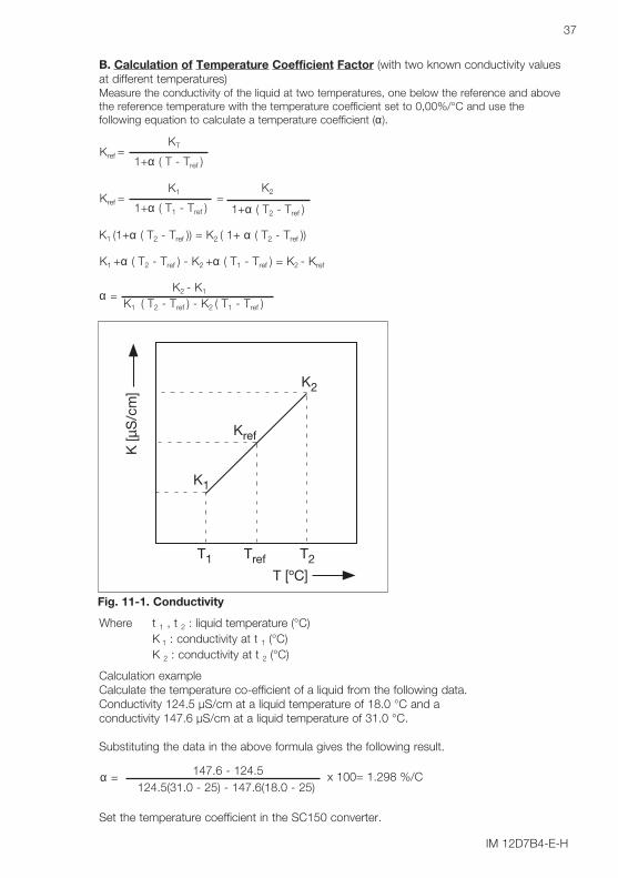
Calculation exampleCalculate the temperature co-efficient of a liquid from the following data. Conductivity 124.5 µS/cm at a liquid temperature of 18.0 °C and a conductivity 147.6 µS/cm at a liquid temperature of 31.0 °C.
Substituting the data in the above formula gives the following result.
Set the temperature coefficient in the SC150 converter.
147.6 - 124.5 x 100= 1.298 %/Cα =124.5(31.0 - 25) - 147.6(18.0 - 25)
Where t 1 , t 2 : liquid temperature (°C)K 1 : conductivity at t 1 (°C)K 2 : conductivity at t 2 (°C)
K2
K1
Kref
T2T1 Tref
T [ºC]
K [µ
S/c
m]
Fig. 11-1. Conductivity
B. Calculation of Temperature Coefficient Factor (with two known conductivity valuesat different temperatures)Measure the conductivity of the liquid at two temperatures, one below the reference and abovethe reference temperature with the temperature coefficient set to 0,00%/°C and use thefollowing equation to calculate a temperature coefficient (α).
KTKref =
1+α ( T - Tref )
K2 - K1α =K1 ( T2 - Tref ) - K2 ( T1 - Tref )
K1 K2Kref = =
1+α ( T1 - Tref ) 1+α ( T2 - Tref )
K1 (1+α ( T2 - Tref )) = K2 ( 1+ α ( T2 - Tref ))
K1 +α ( T2 - Tref ) - K2 +α ( T1 - Tref ) = K2 - Kref

IM 12D7B4-E-H
38
Ammonia 0..50 ppb 0- 90°CAmmonia 15..30% 10-50°CMorpholine 0..500ppb 0- 90°CH2SO4 0..27 % 0-100°CH2SO4 39..85 % -18 - 116°CH2SO4 93..100% 10- 90°CNaOH 0..18% 0-100°CNaOH 30..50% 0-80 °CHCl 0..18% -10- 65°CHCl 22..44% -20-65°CHNO3 0..30% 0-80°CHNO3 35..80% -16-60°C
CheckingWhen the temperature coefficient already set is accurate, the conductivity to be displayedmust be constant regardless of liquid temperature. The following check will make sure thatthe temperature coefficient already set is accurate.If, when the liquid temperature is lowered, a larger conductivity value is indicated, thetemperature coefficient already set is too small.The opposite also applies. If a smaller conductivity value is indicated, the temperaturecoefficient already set is too large. In either case, change the temperature coefficient so thatthe conductivity no longer changes. Matrix compensationThe compensation matrix is a table of temperature and conductivity values at differingconcentrations. These values are used to calculate the temperature compensationapplicable for a particular solution. Choose the component that you will be measuring inyour application, and where appropriate the concentration range. EXAxt will do the rest.
By following the routing:Commissioning>> Measurement setup>> Temp.compensation>> MatrixCommissioning>> Measurement setup>> Temp.compensation>> Matrixyou gain access to the Matrix selection area.
Matrices are available for the common mineral acids and bases. In addition Ammonia andMorpholine are included. In short by using the matrix method, specialist compensation isavailable for the majority of applications in the power industry, water treatment, and chemicalmanufacturing. The following matrices are available initially, but as with all Yokogawaproducts, we are continually striving to improve both the quality and technological content.Further solutions will be added to this list.

IM 12D7B4-E-H
39
11-2. Appendix 2
Calibration Solutions for Conductivity
NOTE:This section should be read in conjunction with the calibration section (Chapter 7) and themaintenance section (Chapter 8). The calibration (cell constant) of a sensor does notchange unless the sensor is damaged.It can also appear to change because of coating of the electrodes, or partial blockage.Because these changes should be handled as described in the maintenance section, itdoes not make sense to regularly recalibrate the SC150.
A calibration check, however, is another matter. When the objective is clearly defined as adiagnostic exercise a regular check can bring an extra level of security and confidence tothe measurement.
Sensor damage, and/or coatings can be difficult to see and the calibration check canconfirm their presence, by a deviation from the known solution conductivity. The remedialaction should be to clean the sensor, and carefully check for blockage or damage (notsimply to recalibrate).
Higher conductivity solutions should be used where possible. The lower the conductivity ofthe test solution, the easier it is to contaminate. Carbon dioxide from the air can be quicklyabsorbed to cause an error. All containers must be suitably clean, and all materials suitablypure. Outside of a well-equipped laboratory these conditions are hard to meet.
Also note that the check must be performed with due regard to the cell constant of thesensor, as it limits the effective working range. The documentation provided with thesensor should be consulted to determine its maximum working value. By using a checkingsolution close to the upper range limit of the sensor, the detection of contamination isbetter. A slightly contaminated sensor may read perfectly at lower conductivity, but showsignificant errors at higher values. This is caused by the early onset of polarization, thefactor that limits the upper range of the sensor in any case. Polarization is seen incontaminated sensors, and it is for this reason that there is a sophisticated polarizationcheck built into the SC150. Details of this diagnostic tool are found in the troubleshootingsection (Chapter 9).
EXAxt SC150 is programmed with the following table of conductivity of Potassium Chloride(KCl) solutions at 25°C. This is used in the Automatic Cell Constant setting calibrationfeature. (See chapter 7 on calibration) The table is derived from the Standards laid downin "International Recommendation No. 56 of the Organisation Internationale de MétrologieLegale".
Table 5-2. KCl values at 25 °C
Weight % mg of KCl / kgmolal (m) of solution Conductivity
0.3 0.001
0.002
0.005
0.01
0.1
1.0
0.1469 mS/cm
0.5 149.32 0.2916 mS/cm
1 373.29 0.7182 mS/cm
3 745.263 1.4083 mS/cm
5 7419.13 12.852 mS/cm
10 71135.2 111.31 mS/cm
74.66

If it is more convenient, the user may make solutions from Sodium Chloride (NaCl orcommon table salt) with the help of the following relationship table. This table is derivedfrom the IEC norm 746-3.
Table 5-3. NaCl values at 25 °C
NOTE:For resistivity measurement the standard resistivity units of the calibration solution can becalculated as follows:R = 1000/G (kΩ.cm if G = µS/cm)
Example: 0.001% weight R = 1000/21.4 = 46.7 kΩ.cm
Weight % mg/kg Conductivity
0.001 10 21.4 µS/cm
0.003 30 64.0 µS/cm
0.005 50 106 µS/cm
0.01 100 210 µS/cm
0.03 300 617 µS/cm
0.05 500 1.03 mS/cm
0.1 1000 1.99 mS/cm
0.3 3000 5.69 mS/cm
0.5 5000 9.48 mS/cm
1 10000 17.6 mS/cm
3 30000 48.6 mS/cm
5 50000 81.0 mS/cm
10 100000 140 mS/cm
IM 12D7B4-E-H
40

IM 12D7B4-E-H
41
11-3. Appendix 3
Sensor selection for the EXAxt SC150
Yokogawa supplies the following sensors, and their application is briefly described. All arecompatible with the EXAxt SC150, and the user must be aware of the sensor configurationfor 2 or 4 electrodes, in order to set the converter correctly.
SC42-SP34 (&SX42-SX34) cc = 0.01 cm-1 2-electrode sensorThis sensor is the first choice for pure and ultra pure water measurements. From0.055µS/cm up to 100µS/cm this is a perfect choice. The measuring range extends to atleast 1000µS/cm, but there are better choices in that range.Almost exclusively used in flow fittings and sub-assemblies. FF40 and FS40. (The -SXsensors are screwed or flanged direct into the process pipework or tanks.)
SC4A-S(T)-XX-002...... cc = 0.02 cm-1 2-electrode sensorThis sensor is a good choice for pure and ultra pure water measurements. From0.055µS/cm up to 50µS/cm this is a good choice. The measuring range extends to500µS/cm, but there are better choices in that range. The "SC4A-" sensors make up arange that use compression adapters or specialized fittings, including retractable.
SC42-SP24 (&SX42-SX24) cc = 0.1cm-1 2-electrode sensorThis sensor should be used for clean and pure water measurements. From 0.2µS/cm upto 1 mS/cm the sensor is fine, with measurement up to 10 mS/cm possible, but there arebetter choices in that range. Mounting of these sensors is as for the ....-SP(X)34 series.
SC4A-S(T)-XX-010...... cc = 0.1 cm-1 2-electrode sensorThis sensor is a good choice for clean water measurements. From 0.5µS/cm up to200µS/cm this is a good choice. The measuring range extends to 2000µS/cm, but thereare better choices in that range. The "SC4A-" sensors make up a range that usescompression adapters or specialized fittings, including retractable.
SC42-EP15(D) cc = 1 cm-1 2-electrode sensorThis sensor is intended as a handy, short sensor. It is easy to fit in a branch (tee) on apipeline, and is good for measurements where the precision is less critical than aconvenient installation. The D version is particularly suited to food applications because ofit's cleanability. Range of application is from 10 µS/cm to 10 mS/cm.
SC42-EP14 cc = 1 cm-1 2-electrode sensorClean cooling and process water applications are where this sensor is used. The bestrange of application is 10µS/cm to 10mS/cm. It is better suited to flow throughinstallations in FS40 and FF40 adapters and fittings, but it can also be used in dip tubes -FD40.
SC42-EP18 cc = 1 cm-1 4-electrode sensorCooling and process water applications are where this sensor is used, including lightfouling. The best range of application is 100µS/cm to 100mS/cm. The four-electrodesystem copes with some contamination from the process, and eliminates the tendency forpolarization to occur at the higher conductivity. It is better suited to flow through installationsin FS40 and FF40 adapters and fittings, but it can also be used in dip tubes - FD40.

IM 12D7B4-E-H
42
SC42-EP04 cc = 10 cm-1 2-electrode sensorThis sensor is in the program for historical reasons. It makes little sense to select thissensor for new applications.It was used mostly for process water and light process solutions. The operating range canbe 1to 100 mS/cm with higher readings having a very high risk of polarization. The SC42-EP18 or the SC42-EP08 (4-el sensors) covers these ranges with much greater certainty ofavoiding polarization.
SC42-EP08 cc = 10 cm-1 4-electrode sensorProcess applications are where this sensor is used, including light fouling. The best rangeof application is 1mS/cm to 500mS/cm. The four-electrode system copes with somecontamination from the process, and eliminates the tendency for polarization to occur atthe higher conductivity. The upper limit is determined more often by chemical compatibility.The epoxy material is attacked by many of the chemicals that are present in highconductivity solutions. It is better suited to flow through installations in FS40 and FF40adapters and fittings, but it can also be used in dip tubes - FD40.
SC42-TP08 (FP08) cc = 10 cm-1 4-electrode sensorThese sensors are for extreme applications. The PTFE or the PVDF used for the body ofthe sensor gives good chemical resistance for the strongly corrosive applications. Thesesensors are intended for use in ranges 10mS to 1000mS/cm. Careful selection of theholder is needed. The PVDF sub-assembly is an obvious choice for the SC42-FP08, andthe PP flow fitting often has sufficient corrosion resistance for the application. In any caseselection must be done with due regard to the process conditions.
0.00001 0.0001 0.001 0.01 0.1 1 10 100 1000
1
2
3
4Cell Constant0.01 cm
0.01 0.1 1.0 10 100 1000 µS/cm
Under usefulrange
Usefulrange
Use 4-el sensor
-1
Cell Constant0.1 cm -1
Cell Constant1.0 cm -1
Cell Constant10 cm -1
mS/cm
The 2-electrode versions (SC42-T(F)P04 do exist, but like the epoxy version (SC420-EP04)they should be discounted for new applications.

IM 12D7B4-E-H
43

IM 12D7B4-E-H
44

45
QIS 12D7B4-E-H 1st edition
Databankweg 203821 AL AmersfoortThe Netherlands
QualityInspectionStandard
YOKOGAWA
Model SC150Conductivity and ResistivityConverter
Introduction
The test equipment needed is :
BOX 1 Resistor decade to simulate the temperature sensor, maximum value 100 kW, adjustable in steps of 0.1 W, minimum accuracy 0.1 %.
BOX 2 Resistor decade to simulate the Conductivity sensor, maximum value1 MΩ, adjustable in steps of 1 W, minimum accuracy 0.1 %.
2 fixed resistors To simulate the load resistance of the mA-outputvalue: 300ΩΩΩΩΩΩ, accuracy 1%.
Multimeter To measure DC currents up to 30 mA, minimum resolution 0.01 mA, (preferably 2) minimum accuracy 0.05 % of reading.
To measure Contact Relays open or close.Sensor cable type WU40 (2 metres) without sensor connection, to connect the input
signals
Connect the SC150 as shown in the figure below. The lower range decade box (BOX 1) toterminals 11 & 12 to simulate the temperature input. Set decade box 1 to simulate 25 ºC,see tables below for the value for the selected sensor. If this box has an earth connection,connect it to terminal 12.Connect the higher range decade box (BOX 2) to terminals 13, 14, 15 and 16, with 13/14and 15/16 shorted at the decade box side. If this box has an earth connection, connectthis to terminal 14.The output terminals are connected through the 300 W load resistor to the mA meter.(Note: current outputs may be measured in turn with the same meter, or simultaneously iftwo meters and load resistors are available).
QIS 12D7B4-E-H
46
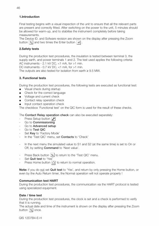
1.Introduction
Final testing begins with a visual inspection of the unit to ensure that all the relevant partsare present and correctly fitted. After switching on the power to the unit, 5 minutes shouldbe allowed for warm-up, and to stabilise the instrument completely before takingmeasurements.The Device ID. and Sofware revision are shown on the display after pressing the Zoombutton and two times the Enter button .
2.Safety tests
During the production test procedures, the insulation is tested between terminal 3, thesupply earth, and power terminals 1 and 2. The test used applies the following criteria:AC instruments - 2.1 kV DC, <1 mA, for >1 min.DC instruments - 0.7 kV DC, <1 mA, for >1 min.The outputs are also tested for isolation from earth ≥ 9.5 MW.
3. Functional tests
During the production test procedures, the following tests are executed as functional test: Visual check during startup Check for the correct language Voltage and current check Contact relay operation check Input contact operation checkThe checkbox ‘Functional test’ on the QIC form is used for the result of these checks.
The Contact Relay operation check can also be executed separately:- Press Setup button - Go to Commissioning- Go to Advanced setup- Go to Test QIC- Set Key to ‘Factory Mode’- In the ‘Test QIC’ menu, set Contacts to ‘Check’
- In the next menu the simulated value to S1 and S2 (at the same time) is set to On or Off, by setting Command to ‘Next value’.
- Press Back button to return to the ‘Test QIC’ menu.- Set Quit test to ‘Yes’- Press Home button to return to normal operation.
Note: if you do not set Quit test to ‘Yes’, and return by only pressing the Home button, oreven by the Auto Return timer, the Normal operation will not operate properly !
Communication test HARTDuring the production test procedures, the communication via the HART protocol is testedusing specialized equipment.
Date / time testDuring the production test procedures, the clock is set and a check is performed to verifythat it is running.The actual date and time of the instrument is shown on the display after pressing the Zoombutton once.
Press the Back button to return to the ‘Test QIC’ menu
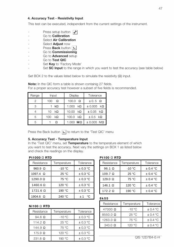
This test can be executed, independent from the current settings of the instrument.
- Press setup button- Go to Calibration- Select Air Calibration- Select Adjust now- Press Back button- Go to Commissioning- Go to Advanced setup- Go to Test QIC- Set Key to ‘Factory Mode’- Set SC Input to the range in which you want to test the accuracy (see table below)
Set BOX 2 to the values listed below to simulate the resistivity (Ω) input.
Note: In the QIC form a table is shown containig 27 fields.For a proper accuracy test however a subset of five fields is recommended.
QIS 12D7B4-E-H
47
Range Input Display Tolerance
2 100 Ω 100.0 Ω ± 0. 5 Ω
3 1 kΩ 1.000 kΩ ± 0.005 kΩ
4 10 kΩ 10.00 kΩ ± 0.05 kΩ
5 100 kΩ 100.0 kΩ ± 0.5 kΩ
5 1 MΩ 1.000 MΩ ± 0.005 MΩ
Pt1000 Ω RTD Pt100 Ω RTD
Resistance Temperature Tolerance Resistance Temperature Tolerance
960.9 Ω -10 °C ± 0.3 °C 96.1 Ω -10 °C ± 0.4 °C
1097.4 Ω 25 °C ± 0.3 °C 109.7 Ω 25 °C ± 0.4 °C
1290.0 Ω 75 °C ± 0.3 °C 129.0 Ω 75 °C ± 0.4 °C
1460.6 Ω 120 °C ± 0.3 °C 146.1 Ω 120 °C ± 0.4 °C
1721.6 Ω 190 °C ± 0.3 °C 172.2 Ω 190 °C ± 0.4 °C
1904.6 Ω 240 °C ± 1 °C
Ni100 Ω RTD 8 k 5 5
Resistance Temperature Tolerance Resistance Temperature Tolerance
94.6 Ω -10 °C ± 0.3 °C 47000 Ω -10 °C ± 0.4 °C
114.2 Ω 25 °C ± 0.3 °C 8550.0 Ω 25 °C ± 0.4 °C
144.9 Ω 75 °C ± 0.3 °C 1263.0 Ω 75 °C ± 0.4 °C
175.9 Ω 120 °C ± 0.3 °C 343.0 Ω 120 °C ± 0.4 °C
231.8 Ω 190 °C ± 0.3 °C
4. Accuracy Test - Resistivity Input
5. Accuracy Test - Temperature InputIn the ‘Test QIC’ menu, set Temperature to the temperature element of whichyou want to test the accuracy. Next vary the settings on BOX 1 as listed belowand check the readings on the display.
8 k 5 5
Resistance Temperature Tolerance
47000 Ω -10 °C ± 0.4 °C
8550.0 Ω 25 °C ± 0.4 °C
1263.0 Ω 75 °C ± 0.4 °C
343.0 Ω 120 °C ± 0.4 °C
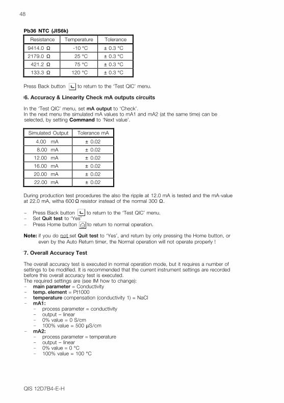
QIS 12D7B4-E-H
48
Pb36 NTC (JIS6k)
Resistance Temperature Tolerance
9414.0 Ω -10 °C ± 0.3 °C
2179.0 Ω 25 °C ± 0.3 °C
421.2 Ω 75 °C ± 0.3 °C
133.3 Ω 120 °C ± 0.3 °C
Press Back button to return to the ‘Test QIC’ menu.
6. Accuracy & Linearity Check mA output circuits
In the ‘Test QIC’ menu, set mA output to ‘Check’.In the next menu the simulated mA values to mA1 and mA2 (at the same time) can be selected, by setting Command to ‘Next value’.
Simulated Output Tolerance mA
4.00 mA ± 0.02
8.00 mA ± 0.02
12.00 mA ± 0.02
16.00 mA ± 0.02
20.00 mA ± 0.02
22.00 mA ± 0.02
During production test procedures the also the ripple at 12.0 mA is tested and the mA-value at 22.0 mA, witha 600 Ω resistor instead of the normal 300 Ω.
- Press Back button to return to the ‘Test QIC’ menu.- Set Quit test to ‘Yes’- Press Home button to return to normal operation.
Note: if you do not set Quit test to ‘Yes’, and return by only pressing the Home button, or even by the Auto Return timer, the Normal operation will not operate properly !
7. Overall Accuracy Test
The overall accuracy test is executed in normal operation mode, but it requires a number of settings to be modified. It is recommended that the current instrument settings are recorded before this overall accuracy test is executed.The required settings are (see IM how to change):- main parameter = Conductivity- temp. element = Pt1000- temperature compensation (conductivity 1) = NaCl- mA1:
- process parameter = conductivity- output – linear- 0% value = 0 S/cm- 100% value = 500 µS/cm
- mA2:- process parameter = temperature- output – linear- 0% value = 0 °C- 100% value = 100 °C
6. Accuracy & Linearity Check mA outputs circuits
7. Overall Accuracy Test
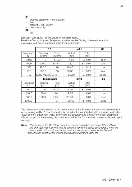
QIS 12D7B4-E-H
49
- S1:- process parameter = conductivity- alarm- setpoint = 500 µS/cm- direction = high
- S2:- fail
Set BOX1 and BOX2 to the values in the table below.Read the Conductivity and Temperature values on the Display. Measure the Actual mA-values and Contact settings using the multimeter(s).
SC mA1 S1
Resistance[Ω ]
Reading[S/cm]
Toler.[S/cm]
Actual[mA]
Toler.[mA]
Open 0 ± 0.01 4.00 ± 0.02 open
1000 100.0 ± 1.5 7.20 ± 0.07 open
500 200.0 ± 3.0 10.40 ± 0.12 open
200 500.0 ± 7.5 20.00 ± 0.26 n.a.
100 1.000 mS/cm ± 15 20.50 ± 0.02 closed
Temperature mA2 S2
Resistance[Ω ]
Reading[ºC]
Toler.[ºC]
Actual[mA]
Toler.[mA]
1000.0 0 ± 0.4 4.00 ± 0.08 open
1194.0 50.0 ± 0.4 12.00 ± 0.08 open
1385.0 100.0 ± 0.4 20.00 ± 0.08 open
3000.0 - 0 20.50 ± 0.02 pulse
The tolerances specified relate to the performance of the SC150 in the controlled environment of the testing facility. Production testing is carried out in combination with a specially calibrated automatic test equipment (ATE). In the field, the accuracy and linearity of the test equipment affects the error in the reading. As much as an additional 0.1 mA may be seen in the mA ouput readings.
Note: The testing of the SC150 is carried out under controlled environmental conditions. The end user may well find that his ambient conditions varies considerably from the ones noted in this certificate. In this case it is necessary to refer to the General Specification sheet for the details of ambient temperature, drift, etc.

QIS 12D7B4-E-H
50

QIC 12D7B4-E-H 1st edition
Databankweg 203821 AL AmersfoortThe Netherlands
QualityInspectionCertificate
YOKOGAWA
Model SC150Conductivity and ResistivityConverter
51

IM 12D7B4-E-H 02-105 (A) QSubject to change without notice Printed in The NetherlandsCopyright ©
UNITED STATES OFAMERICAYokogawa Corporation ofAmerica2 Dart RoadNEWNAN, GA 30265-1040Tel. +1-770-253 70 00Fax +1-770-251 28 00
EUROPEAN HEADQUARTERSYokogawa Europe B.V.Databankweg 203821 AL AMERSFOORTThe NetherlandsTel. +31-33-4641 611Fax +31-33-4641 610E-mail: [email protected]
THE NETHERLANDSYokogawa Nederland B.V.Hoofdveste 113992 DH HOUTENTel. +31-30-635 77 77 Fax +31-30-635 77 70
AUSTRIAYokogawa Austria Ges.m.b.H.Franzensbrückenstrasse 26A-1021 WIENTel. +43-1-2165 043 0Fax +43-1-2165 043 33
BELGIUMYokogawa Belgium N.V./S.A.Minervastraat 161930 ZAVENTEMTel. +32-2-719 55 11Fax +32-2-725 34 99
FRANCEYokogawa Contrôle Bailey S.A.Vélizy Valley18-20 Rue Grange Dame Rose78140 VELIZY VILLACOUBLAYTel. +33-1-39 26 10 00Fax +33-1-39 26 10 30
GERMANYYokogawa Deutschland GmbHBerliner Strasse 101-103D-40880 RATINGENTel. +49-2102-4983 0Fax +49-2102-4983 22
HUNGARYYokogawa Hungaria Ltd.Galamboc u. 301119 BP BUDAPESTTel. +36-1-204 2797Fax +36-1-204 2781
ITALYYokogawa Italia S.r.l.Vicolo D. Pantaleoni, 420161 MILANOTel. +39-02-66 24 11Fax +39-02-645 57 02
SPAINYokogawa España S.A.C/Francisco Remiro, N°2, Edif. H28028 MADRIDTel. +34-91-724 20 80Fax +34-91-355 31 40
UNITED KINGDOMYokogawa United Kingdom Ltd.Stuart Road, Manor Park,RUNCORNCheshire WA7 1TRTel. +44-1-928 597100Fax +44-1-928 597101AUSTRALIAYokogawa Australia Pty Ltd.Private mail bag 24Centre Court D325-27 Paul Street NorthNORTH RYDE, N.S.W. 2113Tel. +61-2-805 0699Fax +61-2-888 1844
SINGAPOREYokogawa Engineering Asia Pte.Ltd.11, Tampines Street 92SINGAPORE, 528872Tel. +65-783 9537Fax +65-786 2606
JAPANYokogawa Electric Corporation2-9-32, Nakacho, Musashino-shiTOKYO, 180Tel. +81-422 52 5617Fax +81-422 52 0622
SOUTH AFRICAYokogawa South Africa (Pty) ltd.67 Port Road, RobertshamSouthdale 2135,JOHANNESBURGTel. +27-11-680-5420Fax +27-11-680-2922
YOKOGAWA
CENTRAL/EAST REGIONVia Yokogawa Austria:Czechia, Slovakia, Poland,Croatia, Slovenia,Jugoslavia, Bulgaria,Romania, Macedonia,Bosnia & Herzegovina
Distributors in:Denmark, Finland,Greece, Norway,Portugal, RussianFederation, Sweden,Switzerland and Turkey.
Block 03, 11-00
ISO 9001
CERTIFICATEDFIRM