instructions for: chip hyde’s double · pdf fileslide onto pre-fitted tubes and are...
TRANSCRIPT

Instructions for: CHIP HYDE’S DOUBLE VISION
Copyright 2004 - Chip Hyde Products 520-458-1414 officewww.chiphyde.com
Warning An R/C aircraft is not a toy! If misused, it can cause serious bodily harm and damage to property. Fly only in open areas, preferably AMA (Academy of Model Aeronautics) approved flying sites, following all instructions included with your radio and engine. Do not fly this or any other model airplane after consuming any alcohol and/or drugs (both legal and/or illegal).


Contents of Manual Cover page Introduction Kit Contents:
- Items needed to complete Double Vision - Tools needed to complete - Adhesives
Building Instructions Wings:
- Hinging the ailerons - Fitting of aluminum wing tubes - Bottom wing-tube
Fuselage: - Fin and rudder - Tailwheel - Mounting the engine - Fuel tank - Cowl - Main landing gear - Removable Top deck
- Cabane assembly - Horizontal Stabilizer and Elevators
Final Assembly Interplane struts Radio installation Recommended Control throws Computer radio programming options

Introduction
The Double Vision is a highly aerobatic Bi-plane designed and sold by world renowned aerobatic RC pilot Chip Hyde who is a multiple USA National, World and TOC champion. The plane is fully capable of both precision aerobatics and full blown more extreme 3-D aerobatics.
The Double Vision features rapid assembly due to plug-on wings and plug-on stabs that not only make it quick, but easy and accurate to construct. The wings and stabilizers slide onto pre-fitted tubes and are aligned by pre-installed anti-rotation pins. There is a minimal amount of gluing and drilling required to complete the assembly. This greatly reduces the time to assemble and get you to the flying field.
The Double Vision can be disassembled and broken down into four wing panels, two stabilizer halves and a fuselage to facilitate transportation in almost any size of vehicle. The larger the vehicle, the less you will need to remove!
Assembly at the field is greatly simplified with easy access to the wing retention and
interplane strut bolts. One ball-wrench, a couple of minutes of assembly and a tank of 2-cycle gas will get you into the air.
The plane is designed for gas motors in the 50-cc category. The recommended motor is the DA 50 that is shown in the assembly instructions. The final choice of power plant is left up to the builder.
A computer radio is recommended for the Double Vision. This is primarily because
then the Pilot can take advantage of the full capabilities of this plane. Intended use This plane should not be regarded as a toy. This is an advanced aerobatic plane and is recommended for pilots who are well beyond the trainer-stage and are comfortable with flying at least an aerobatic sport plane. Warranty If you have any problems, contact Planes Plus, Inc. 630-904-9983. Parts will be exchanged/replaced once the original item is returned to Planes Plus at the owner’s expense.

Kit Contents
Principal components of Double Vision Parts: Canopy - unpainted 2 x top wings and ailerons 2 x bottom wings and ailerons 1 x Cabane center piece 2 x Stabs 2 x Elevators 1 x Fin 1 x Rudder 1 x FG cowl 1 x Fuselage 1 x 1” Aluminum Top wing-tube 1 x 1” Aluminum Bottom wing-tube 1 x stab tube Top & bottom 2 x 3” x 1/4" wing rods Stab anti-rotation rod
2 x Cabane struts and 2 x braces Landing gear 2 x Wheel pants Parts not shown. 2 x horns and c/sunk screws for rudder 2 x horns and c/sunk screws for elevators 4 x horns and c/sunk screws for ailerons 8 x aluminum end strut attach points 4 x 4mm x 20mm screws and washers 4 x 3mm x 12mm with nuts and washers for Cabane assembly 2 x 3mm x 30mm and washers - Center rib bolts 10 x 15mm m/c screws 2 x 1" square ply plates for wheel pants 1 x Lite ply tank floor 2 x 3mm wheel pant retaining bolts

Items needed to complete Double Vision 50 cc Motor and Propeller 3-1/2" Tru-turn spinner 1 x 16-24 oz Tank 2 x 3-3.5 main wheels 3 12” 4-40 all-thread (Elev/Ail. Pushrods) 1 36” carbon tube (to slide over all thread for pushrods) 8 x 4-40 pin and 4-40 connector ball-links 1 Heavy Duty Pull-pull 4-40 cable wires kit 4 x aileron servos (100 Inch oz) 1 x rudder servos (130 Inch oz) 2 x elevator servos (130 Inch oz) 1 x throttle servo Extn leads - 2 x Top wings
- 2 x Bottom wings - 2 x Elevator servos - 1 Y-lead from RX Left Side - 1 Y-lead from RX Right Side
Receiver & S/W Battery flight pack Ignition battery S/W for ignition Axles 4-40 x 1/2” bolts and blind nuts for wheel pant retention. Tools needed to complete Modeling knife Fine Blade hacksaw File Electric drill and selection of bits 3-mm tap Phillips screwdriver (Small) Pliers Allen wrenches USA and Metric. Dremel sanding drum tool Adhesives Thin CA Medium CA Slow CA CA kicker (optional) 5 Minute epoxy RC-56 canopy glue (optional)

DOUBLE VISION - BUILDING INSTRUCTIONS Introduction:
Welcome to the building of your Double Vision. The fully assembled Double Vision is approx 83” long. These instructions have been sequenced to make the handling of the plane as easy as possible. For example, the stabilizer halves and engine are not installed until nearly the very end of the assembly process. This makes the plane easier to turn over and maneuver in your workshop.
Items such as radio equipment and engine, etc. are shown as options and examples. The builder is at liberty to substitute products of their own preference.
Covering: It is important to take an iron set at a low setting and go over all of the seams and stripes. This will help prevent the stripes from coming up. Wings:
The Double Vision has four wing panels. Two are top wing panels and two are bottom wing panels.. The top wing panel has the servo on the bottom surface and shows two recessed holes with blind nuts for the interplane struts, on the same side. The bottom wing panels have the servo on the bottom and the two recessed holes for the interplane struts on the top of the wing surface.
Underneath of top wing showing servo opening and Interplane-strut hard points
7

Hinging the ailerons:
Top wing panel and aileron with Mylar hinges Building Tip - Keep each aileron with the wing panel that they came with to maintain correct alignment later in the assembly process.
Select a wing panel and position the Mylar CA hinges centrally in each slot using two pins to prevent hinges moving too far into their slots.
Two pins used to “center” the Mylar hinge Building tip - Keep a rag nearby that has been dipped into Acetone. This can be used to wipe up any CA that runs. Use denatured alcohol to clean up later.
8

All hinges in place. Pins are removed before gluing.
Fully deflect the aileron while keeping the aileron gap as small as possible. Then drip in Thin CA adhesive onto the hinges. Do this on both sides of the hinges. Flex the ailerons periodically over a period of about 5 minutes to prevent the aileron covering from attaching itself to the wing.
Repeat the hinging process for all four ailerons and wing panels
9

IMPORTANT DO NOT TRY TO INSTALL THE CLEVIS INTO THE BALL BEARING CONTROL HORNS BUY SPREADING THE CLEVIS WITH A FLAT TIP SCREW DRIVER, THAT IS NOT THE WAY THESE ARE DESIGNED TO WORK. UNSCREW THE PHILLIPS HEAD BOLT AND REMOVE IT COMPLETELY FROM THE CLEVIS ITSELF. THEN SLIP THE HORN TROUGH THE EMPTY SLOT AND REINSTALLL THE SCREW IN THE CLEVIS . NOT FOLLOWING THESE INSTRUCTIONS CAN CAUSE FAILURES IN THE BALLBEARING FROM THE EXCESSIVE SIDE LOADS PUT ON THE INNER RACE. THAT IS NOT THE TYPE OF LOADS THESE BEARINGS ARE DESIGNED TO WITHSTAND. THEY ARE DESIGNED TO GIVE TO PROVIDE A FRICTIONLESS CONNECTION AND THAT THEY DO VERY WELL. WE RECOMMEND TO USE THE SUPPLIED CLEVIS ONLY AS THEY WERE DESIGNED SPECIFICALLY FOR THIS HORN. CHIP Aileron Servo installation:
Select a wing panel and a servo. Add an extension lead to the servo so that the lead can exit at the root of the wing. Ensure the servo extension connection is taped or tied, so that it cannot be easily pulled apart once installed. Locate the “pull-cord” that was pre-fitted to each panel. Remove the piece of wood used to retain the cord. Use this cord to pull the aileron extension through the wing panel. Use a 3/64” drill bit to pre-drill and secure the servo in place with four servo screws.
Pull cord end can be found in servo bay and at wing root.
10
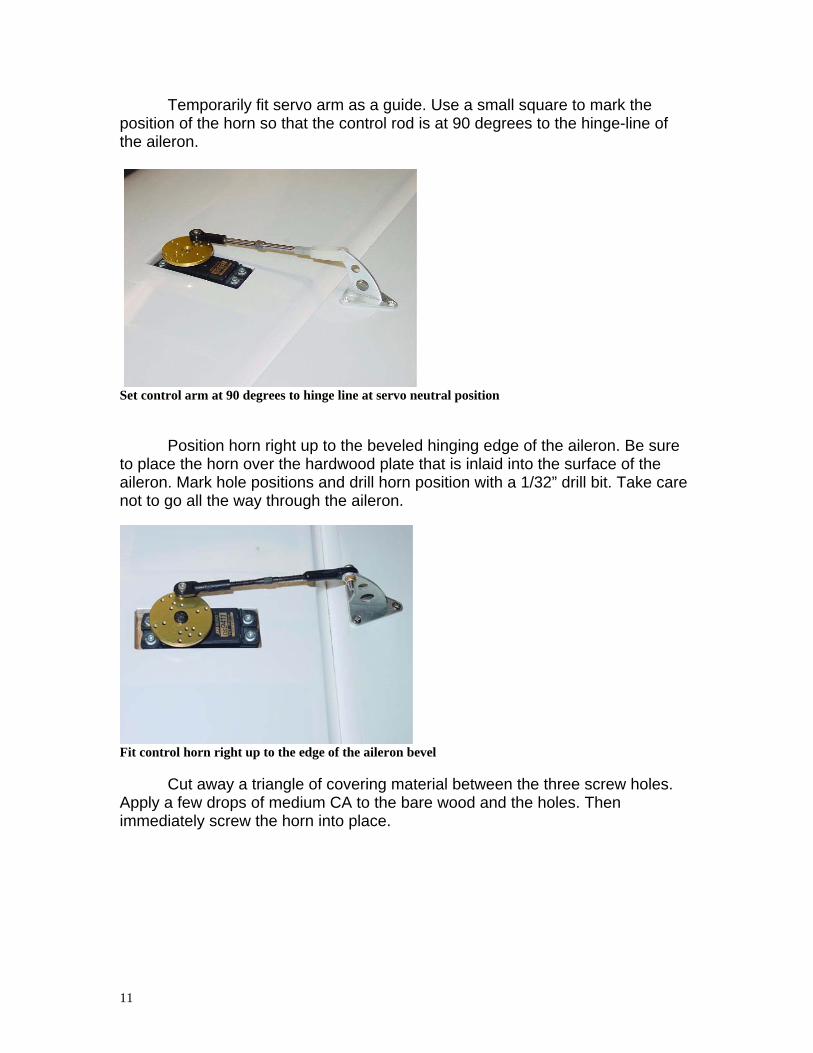
Temporarily fit servo arm as a guide. Use a small square to mark the position of the horn so that the control rod is at 90 degrees to the hinge-line of the aileron.
Set control arm at 90 degrees to hinge line at servo neutral position
Position horn right up to the beveled hinging edge of the aileron. Be sure to place the horn over the hardwood plate that is inlaid into the surface of the aileron. Mark hole positions and drill horn position with a 1/32” drill bit. Take care not to go all the way through the aileron.
Fit control horn right up to the edge of the aileron bevel
Cut away a triangle of covering material between the three screw holes. Apply a few drops of medium CA to the bare wood and the holes. Then immediately screw the horn into place.
11

Attach the horn using CA and counter-sunk screws
Connect pushrod and set aileron position to neutral. Set end-points and rates as per recommended throws. A long extension cord can be used to set up each wing panel individually. Building tip - The use of a control surface throw indication meter is highly recommended. Each wing/aileron can be set individually by using your receiver before installing it in the plane. Use four extension leads (See aileron options at rear of manual). Mark each lead so that it relates to its own wing panel.
Repeat the servo installation for all four wing-panels
12

Fitting of Aluminum wing tubes:
The Double Vision has four plug-on wing panels that are retained by 3x12-mm screws positioned at each end of two wing tubes. Pieces of hardwood have been inlaid into the surface of the wing before the covering was applied. It is important that the 3x12-mm screws go through these hard pieces of wood.
To assure the wing tube is drilled correctly center the tubes in the fuselage and top rib before drilling through the hard points that are already installed in the bottom of each wing.
Building tip - A probe light or a small, key-ring type flashlight will help with this task.
Locating the position of the wing retaining screw Building tip - use a 1” dowel such as a broom handle inserted in the wing tube sleeve to provide resistance as the hole is drilled. This will help create a cleaner exit for the drill bit. It will also prevent the drill bit from going too far into the other side of the tube. Always remove any debris before inserting the wing tube. Do this for all four wing-panels.
13

Top wing-tube:
Insert tube into your wing panel of choice. Add Cabane-rib. Insert into other wing. Measure the exposed aluminum tube. Cut off a length equal to the exposed amount plus about 1/16”. This will ensure that the parts can be pushed together. Do not remove more than the recommended extra 1/16” from the wing-tube length.
Reinsert the wing tube all the way into one wing panel. Mark the aluminum tube and drill and tap the aluminum tube with a 3-mm or 4-40 thread. (Builders Option) Building Tip -It is advisable to use the 1/8” drill bit to mark the position for the hole to be threaded. A few turns of the bit by hand will leave a clear mark on the aluminum wing tube. Remove the aluminum wing-tube and then drill the correct size hole for a 3-mm tap. This prevents the drill from distorting the hole in the wing itself. A drop of thin CA will strengthen the wood around the hole.
Aligning the thread tap with the wing.
Re-insert the wing-tube and use the wing to correctly align the 3-mm tap. Remove all debris from wing and wing tube. Building Tip - The aluminum tube is relatively thin walled. A wooden or plastic insert will help to add more thread depth. A hardwood dowel or a short section of PVC pipe will work well. Select a slightly larger diameter PVC pipe. Cut about a 1/2” length. Then cut a slot that will allow the pipe to be compressed and be pushed inside the wing tube. Drill a matching hole in the PVC. The thread can now be tapped with the tube in position to get the correct alignment.
Use a 3-mm screw and washer to hold the tube in the wing. Insert the top wing aluminum anti-rotation pin, (about six inches long), and slide on the center-rib onto the wing tube.
14

NOTE center rib supplied is approx. 3 inches wide
Now fit the second wing to the wing tube and align with the anti-rotation pin. Enlist the help of a friend or family member to help you push the two wing halves firmly together. Then repeat the process that you used to mark and fit the first 3-mm screw. This completes the wing tube installation for the top-wing. Note: Although it is a common disassembly practice to leave the wing-tube secured in one wing panel, it is still advisable to mark the aluminum wing tube Left & Right, and Top & Bottom, to ensure easy and accurate future 3-mm screw alignment.
15

Bottom wing-tube:
This is a similar process to the top wing. This time, the fuselage will be used to help establish the correct length of the bottom wing tube.
Wing-tube shown in fuselage, anti rotation pins are now installed in the wing
Insert tube into your wing panel of choice. Insert wing and tube into fuselage then add the other wing. Measure the length of the exposed aluminum tube. Remove wing tube from fuselage and wing. Cut off a length equal to the exposed amount plus about 1/16”. This will ensure that the parts can be pushed together. Do not remove more than the recommended extra 1/16” from the wing-tube length. Re-insert the wing tube all the way into the wing panel. Drill and tap for 3-mm bolt.
Building Tip - It is advisable to use the 1/8” drill bit to mark the position for the hole to be threaded. A few turns of the bit by hand will leave a clear mark on the aluminum wing tube. Remove the aluminum wing-tube and then drill the correct size hole for a 3-mm tap. This prevents the drill from distorting the hole in the wing itself. A drop of thin CA will strengthen the wood around the hole.
Insert the wing tube in place and hold in place with a 3-mm screw and washer. Fit the lower wing anti-rotation pins, (approx 3” long), into the bottom wings. These pins need to be epoxied into each wing panel with 5 minute epoxy. (be sure to clean and scuff each pin where they are to be glued.) Now fit the second bottom-wing and enlist the help of a friend or family member to help you push the two wing halves firmly together. Then repeat the process that you used to mark and fit the first 3-mm screw. This completes the wing tube installation for the bottom wing. Note: Although it is a common disassembly practice to leave the wing-tube secured in one wing panel, it is still advisable to mark the aluminum wing tube Left & Right, and Top & Bottom, to ensure easy and accurate future 3-mm screw alignment
16

Fuselage: Fin and rudder:
Rudder and fin showing ply alignment tongue
The fin is pre-keyed for accurate alignment. Remove the rudder and the Mylar hinges before gluing the fin in place.
Remove the covering from the bottom of the fin and From the sides of the stern post before gluing
17

Glue the fin in place with 5 or 15 minute two-part epoxy resin and allow to
fully cure.
Clamps holding fin in place while epoxy resin cures.
Fit a horn equal and opposite on each side of the rudder for the pull-pull cables. Ensure that they are located on the hardwood inserts in the middle of the rudder. Hinge the rudder in exactly the same way as the ailerons.
Pre-glue rudder with medium CA and immediately fit the horn with counter-sunk screws.
18

Fit servo in the servo tray located under the canopy deck. Connect up pull-pull
cables to rudder. Note: Rudder does not require large throws and does not have a bevel on the fin post. Make sure that the rudder does not bind on the hinge post.
View tray for rudder servo, receiver and battery. Tailwheel: Use supplied Tail wheel and mounting screws
19
Fuel tank: Install the supplied tank floor in the fuselage making sure to have either tie wraps or Velcro already looped through the floor. This will allow for easy installation and removal of the tank, and if required. We recommend putting the tank floor over the landing gear plate, but did not install it to give the option of location to the builder. Cowl:
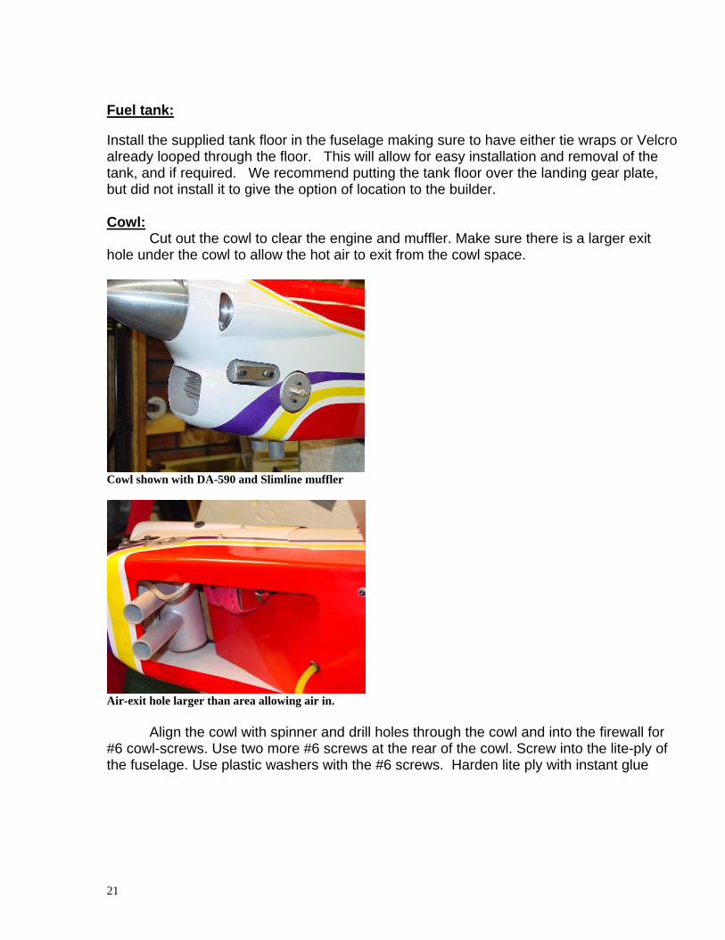
Cut out the cowl to clear the engine and muffler. Make sure there is a larger exit hole under the cowl to allow the hot air to exit from the cowl space.
Cowl shown with DA-590 and Slimline muffler
Air-exit hole larger than area allowing air in. Align the cowl with spinner and drill holes through the cowl and into the firewall for #6 cowl-screws. Use two more #6 screws at the rear of the cowl. Screw into the lite-ply of the fuselage. Use plastic washers with the #6 screws. Harden lite ply with instant glue
21

Main landing gear: Fit wheel and axle to each leg. Allow room for wheel pant to go between wheel and U/C leg. Use a Dremel sanding drum to remove enough material from the opening to ensure a 1/4” clearance all around the wheel.
Wheel pants
Glue plywood square inside the wheel pant. Notch wheel pant to slide over axle. Mark location of wheel pant retaining screw (4-40 or 3-mm). Drill out and fit a blind-nut inside the wheel pant.
Notch for wheel axle nuts and hole for retaining screw.
22

Blind nut for wheel pant bolt.
Hold wheel pant on with lock washer and thread locking compound.
23

Removable Top deck:
Top deck/canopy retaining latch comes already installed
Canopy . Trace the outline of the canopy on the removable deck. Create a pinhole
pattern inside the traced line approximately 3/16” wide. Run a bead of slow CA along the pin-hole-line. Place the canopy over the lines and hold in place until dry. Leave rear of canopy unglued to allow for canopy expansion and contraction.
Alternatively, the canopy can be held in place with RC-56 canopy glue. This is a slower process. More covering material needs to be removed. A complete strip of covering 1/8” wide should be removed to give the glue direct contact with the wood. The canopy then needs to be held in place with masking tape overnight. Building option: Harden area around hole for top deck/canopy latch. Use RC car body window tint for a quick and easy canopy tint. Spray lightly on inside of canopy
Sample picture of canopy (The canopy is not painted in the kit)
24

Cabane assembly: The Cabane consists of four pieces of aluminum. Two “A” shaped pieces and two
straight bars. The center rib contains two blind nuts that are used when bolting the rib to the Cabane assembly. It is important to compare the two “A-frames”, because one is about 1/4” longer than the other. The longer piece goes to the front of the Cabane. The cross-braces can be bolted to the inside or outside of the frame. Assemble the aluminum parts with 3-mm nuts and bolts, but do not tighten them yet. Place the assembly on the fuselage and fasten with four 3-mm bolts. When all the fuselage bolts are in place, tighten up the whole assembly. Be sure to use a thread locker on all of these bolts. Now take two long 3-mm bolts & washers and fit the center rib to the top of the Cabane. Note: This structure is designed to be strong enough to handle flight-loads, but it is not intended to
be used as a carrying handle. LOCTITE ALL CABANE BOLTS
Three-quarter view of Cabane and wing rib (Kit has 3” Center Rib)
Close up of center rib retaining bolt and join with cross-braces
25

Aileron lead exit in center rib - grommet is optional
An option is to hold the Aileron extension leads held in place with heat shrink tubing
26

Horizontal Stabilizer and Elevators:
The Double Vision has a plug-on stab that fits in a very similar manner as the wings. Hinge elevator halves. Locate hard points in stab half and drill hole for 2-56 bolt. Use fuselage to establish correct spacing of screws. Building tip -To get a better thread-grip in the CF tube, the head of a 1/4 x 20 nylon bolt will provide additional purchase inside the tube.
Carbon fiber stab-tube and anti-rotation pin.
27

Attach long extension leads to the two elevator servos. Thread leads
through the servo openings in the fuselage. Pre-drill holes for the servo-screws and fasten servos in place.
Building option - If only one channel is used for the elevator, then one servo has to rotate in the opposite direction If two channels are employed, label the leads with the name or number of the channel they belong to. This will ensure that servos do not get reversed when the receiver is installed.
Fit elevator horns in line with servo arms. Make sure to screw into hard surfaces on the elevators. Connect servo to horns. Center the elevator halves and set throws equal up and down and equal both sides.
Elevator servo hook-up, Note retaining screw for Stab tube.
View showing both servos and horns.
29

Final Assembly: Interplane struts:
Strut hard-point with threaded stud removed - Use thread locking compound to hold stud in place.
Insert studs approx. flush with wing surfaces
Label interplane struts and wing for quick reference at the flying field.
30

Interplane strut details
Wing hard points recess into the interplane struts. The 3-mm bolts thread into the struts from the other side.
3-mm bolts and nylon washers hold struts in place.
31

Radio installation: DA-50 is a large 2-cycle motor and every care should be taken to isolate electronic components from vibration. This includes the battery receiver, ignition unit, switches and any voltage regulator(s) employed. It is also recommended to use a 1” square heat sink with a voltage regulator to dissipate any heat created from driving eight servos, especially digital servos.
The receiver antenna should be kept as far away from elevator servo-leads and pull
-pull wires as possible. A thin plastic will help in routing the antenna near the top of the fuselage. Building tip - Center of Gravity assessment. The recommended Center of Gravity range is 8.5 - 9.5” measured from leading edge of top wing. This is just behind the rear Cabane. This is done with the wings off. Use the positioning of the receiver battery and ignition battery to assist in adjusting the Center of Gravity.
32

Recommended Control throws
one inch arms on ail, and elev. 40% expos on LR and 60% on HR. AFR on elev. rudder and Ail 140% and then the dual rates around 40-50% Pmix, rudd-elev needs to get 7% up elev with rudder both ways, and 5% rudder to ail. Left rudder, Right ail and vice versa
Low Rates 3-D Rates
Rudder
20 degrees 35 degrees
Ailerons
13 degrees 25 degrees
Elevator
15 degrees 40 degrees
8.5-9.5” from the leading edge of the top wing is the beginning center of gravity range
33

Some computer radio priming options: Four-ailerons -
The most desirable load sharing option is to use two receiver channels and two Y-leads. One for left ailerons and one for the right ailerons. Most of today’s computer radios offer this option. One channel; being the aileron channel and the other, being a standard or user-selected mix option.
A two-channel double Y-lead installation allows the use of the Flaperon option, (Elevator can be linked to move the ailerons up and down in concert). It also allows the use of the Flap option (A switch or rotary/slider control can be employed to lower or raise the ailerons as a form of flaps.).
The Flaperon option can be used to tighten loops or aid in landings and take-offs. The Flap option allows the pilot to experiment with very slow flight or high angle-of-attack maneuvers such as “Harriers” or “Waterfalls”, etc.
Please note that the above is only one way of several that you can hook up the ailerons. Depending on your personal preferences other ways may be desired. Please enjoy your Chip Hyde Design and feel free to contact us with any Questions or concerns. Chip
34