instructions for filing plans - welcome to · pdf fileinstructions for filing plans &...
TRANSCRIPT

INSTRUCTIONS FOR
FILING PLANS & GUIDELINES FOR THE DESIGN OF
SIDEWALKS, CURBS, ROADWAYS AND OTHER INFRASTRUCTURE COMPONENTS Booklet revised July 22, 2010 Cover page revised August 28, 2015

TABLE OF CONTENTS
SECTION TITLE PAGE I Introduction 1 II Professional Certification 1 III Coordination with Capital Projects 1 IV Instructions & Submissions 1 V Waivers 3 VI DOT Approval/Review of Design Elements 3 VII Final Acceptance of Work by DOT 4 VIII Sidewalks 4 General requirements 4 Ribbon sidewalks 4 Sidewalk widths 5 Material 5 Access to buildings for people with disabilities 6 Drainage and slopes 6 Vault covers 6 Grates 6 Retaining walls 7 Cellar doors 7 Elevator doors 7 IX Curbs 7 General requirements 8 Curb types 8 Horizontal alignment 9 Vertical alignment 10 Curb Cuts 10 Corner sites 11 Sites at T intersections 12 X Roadways 12 General requirements 12 Extent of Pavement responsibility 12 Quality of pavement required 12 Required material 12 Roadway geometric design 13 Gutter slope 13 Crown/Cross slope 14 Transition to adjacent road areas 14 Curb reveal 15 XI Utilities 15 General requirements 15 Location of above-ground utility structures 15 Allowable tolerances for flush structures 16 Provision of utilities on virgin streets 16 XII Drainage 16 General requirements 16
Location of street drainage inlets 16 Hydraulic calculations and adequacy 16 Existing non-standard storm drainage structures 16 Damage to existing drainage structures 17 XIII Encroachments 17 General requirement 17 Bollards 17 XIV Trees 17 General requirements 17 APPENDICES 18 Appendix A Sidewalk, Curb & Roadway Application (SCARA) Appendix B Cover Sheet Format for All Plan Types Appendix C Requirements for Preparing a Topographical Survey Appendix D Instructions for Preparing Plan Views Appendix E Instructions for Preparing Profile Views Appendix F DOT Design Directive No. 83-S2
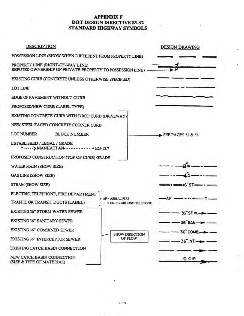
Standard Highway Symbols
Appendix G Glossary of Highway Engineering Terms Appendix H How to Set Your Top of Curb Elevations Appendix I Common Errors and Problems in Design Plans Appendix J Distinctive Sidewalk Appendix K Administrative Code 19-112 (Ramps on Curbs) Appendix L Dot Design Directive No. 30

I INTRODUCTION
A) Every owner developing property is required to have a sidewalk, curb and paved roadway along the public right-of-way abutting the property.
B) The Sidewalk, Curb & Roadway Application (SCARA), except as provided in
IV.B., and all other appropriate forms, plans and certifications must be submitted to the satisfaction of the New York City Department of Transportation (DOT).
C) All public infrastructure work shall be designed and installed in compliance with
current highway engineering practice, the latest version of this publication (refer to Sections VIII to XIV below), and the latest versions of these other DOT publications: Standard Details of Construction, Standard Specifications, and Highway Rules.
II PROFESSIONAL CERTIFICATION
A) A property owner may install the required street infrastructure without prior review of the plan(s) by DOT under a process of professional self-certification. DOT plan review will not be required when a Professional Engineer, Registered Architect or Registered Landscape Architect self-certifies that the proposed infrastructure work complies strictly with the requirements of the DOT publications listed above in Section I.C. and meets or exceeds DOT’s standards and specifications. Self-certification consists of filling out and signing page three (3) of SCARA (“Statement of Professional Certification”) and signing the correct Certification Type block and attaching it on the plan.
B) If the application (SCARA) is not professionally self-certified, then the
Certification Type block need not be included on the plan. However, full DOT review and approval must be obtained before work can begin.
III COORDINATION WITH CAPITAL PROJECTS- ALL AGENCIES: CITY, STATE, FEDERAL & PUBLIC AUTHORITIES
A) In some cases, the required infrastructure work may be proposed for installation
by an agency or authority under a capital improvement project. It shall be the sole responsibility of every applicant to examine all capital plans to see whether any such work is planned. If so, the applicant shall coordinate the improvements with the appropriate agency or authority.
IV INSTRUCTIONS & SUBMISSIONS
A) For each project, every applicant shall submit 3 original (original signature and professional seal, page 3 of the application) Sidewalk, Curb & Roadway
1

Applications (SCARA). Applicant shall check every box that applies to his/her project. (For example, if the applicant/property owner wants to install a special paver and bollards on the sidewalk, he/she will check the box “Sidewalk” and the boxes “Special Paver” and “Bollards” under the “Sidewalk” category). SCARA is a three-page form. See Appendix A.
B) SCARA IS NOT REQUIRED IF ONLY PLAN TYPE A IS CHECKED.
C) Every applicant shall submit the following:
1) The correct Plan Type as required by SCARA:
a) If more than one box is checked, the most detailed Plan Type shall be submitted. (Plan Type F is the most detailed; Plan Type B the least detailed.) For a description of the different Plan Types see page 4 of Appendix A.
b) Plan cover sheet- formatted as per Appendix B-1. c) Include the following, if required by SCARA:
(i) Topographical Survey– see Appendix C. (ii) Plan View– see Appendix D. (iii) Profile View– see Appendix E. (iv) Standard Highway Symbols– see Appendix F. (v) Glossary of Highway Engineering Terms–
see Appendix G.
2) The correct Certification Block as required by SCARA, for self-certified plans. The Certification Type is to be put into DOT Block format, and the Block is to go on the plan cover sheet as per Appendix B-1. Submit the correct Certification Type based on the box(es) checked on SCARA. If more than one box is checked, applicant shall combine the information into one certification block. See Appendix B-4 that shows Certification Types 1 through 11, and a sample of a combined certification of 4 & 7.
3) Written approval from the Landmarks Preservation Commission or the
Public Design Commission of the City of New York, if applicable (applicant must check to see if the project is in a landmarked area or district).
4) Material Testing, if required by SCARA.
5) Maintenance Agreement, if required by SCARA.
6) Statement of Professional Certification to accompany SCARA (which is
page 3 of the Application), for self-certified plans. See Appendix A.
2

V WAIVERS
A) A property owner may request a waiver of any requirement of the New York City Department of Transportation (DOT).
B) The request shall be prepared in writing by a professional architect, engineer or
landscape architect and shall have an original seal and signature affixed. C) It shall be submitted to DOT’s Bureau of Permit Management & Construction
Control (address noted in Section VI.A. below). D) Supplementary materials must be submitted to support the waiver request, such
as maps, drawings, traffic reports, calculations, affidavits, etc. No consideration will be given without complete and adequate documentation.
E) A waiver may be granted at the discretion of the DOT Commissioner
(Commissioner), except where prohibited by law.
VI DOT APPROVAL / REVIEW OF DESIGN ELEMENTS
A) All elements of a proposed design that require approval and/or review by DOT as
specified in this publication shall be submitted to:
New York City Department of Transportation Bureau of Permit Management & Construction Control
55 Water Street, Concourse Level New York, NY 10041
Attn: Permit Management/Plan Examination B) Each submittal shall include:
1) Completed 3 original Sidewalk, Curb & Roadway Applications
(SCARA), as per Section IV.A. See Appendix A.
2) All SCARA requirements as determined by the scope of the project as per Section IV.C. above.
3) All supplementary materials as specified in Sections VIII through XIV
below.
4) Any additional material required by DOT.
3

VII FINAL ACCEPTANCE OF WORK BY DOT
A) All work in the public right-of-way abutting the property may be reviewed by DOT for compliance with the plan and with all applicable rules of the New York City Department of Transportation. DOT acceptance will be based upon any or all of the following:
1) Visual inspection of field installations.
2) Verification of as-built grades and alignment using surveying instruments
or slope-meters on an audit basis. VIII SIDEWALKS
A) GENERAL REQUIREMENTS
1) Every property being developed shall have a sidewalk along its entire development frontage, including the corner quadrant, where applicable.
2) The sidewalk shall generally extend from the mapped right-of-way line to
the curb, except for ribbon sidewalks (see Section B. below) and other site-specific applications.
3) An existing concrete sidewalk may be left in place, provided it is at the
correct alignment and pitch, if it was built and maintained to DOT standards.
4) For a discussion on “How to Set Your Top of Curb Elevations” see
Appendix H. Also refer to Appendix I: “Common Errors and Problems in Design Plans.”
B) RIBBON SIDEWALKS
1) Permitted usage: Areas zoned R-1 through R-6 only.
2) Permitted width: 5’ or as required to match the existing ribbon width in
the immediate neighborhood.
3) Corner lots: Full-width sidewalk required for the corner quadrant.
4) Dirt areas adjacent to the ribbon. a) Grass required everywhere for erosion control. b) Fire hydrants in dirt areas: 5’ x 5’ concrete slab of 6” thick
concrete on 6” crushed stone base extending from the curb to the sidewalk required. When a sidewalk is waived, the hydrant pads shall still be provided.
4

C) SIDEWALK WIDTHS
1) Fully developed areas
a) Replacement sidewalks shall be built to the existing width when: i) The block meets the criteria defined in Section IX.C.1.a.
(under CURBS). ii) The existing width is consistent with the general sidewalk
width in the immediate neighborhood.
2) All other cases a) The sidewalk width shall be determined by DOT. The applicant
shall submit the following: i) City Section Map. ii) Survey prepared as per DOT requirements. iii) Sketch showing the sidewalk widths on the block in
question, the block opposite, and preceding and following blocks.
D) MATERIAL
1) Required: Standard specification concrete only.
2) Permitted alternative: As per DOT’s Special Street Pavement
requirements. See Appendix J: Distinctive Sidewalk
3) Landmark Districts (designated and pending) a) Existing non-concrete sidewalks: DOT approval of replacement
sidewalk required.
4) Slip resistance of all materials a) Min. friction factor (static) Surface
.6 Level .8 Ramps 5) Test method: As required under DOT’s Special Street Pavement
requirements.
E) ACCESS TO BUILDINGS FOR PEOPLE WITH DISABILITIES
1) New and existing buildings should be accessible to people with disabilities in accordance with the Americans with Disabilities Act (ADA).
F) DRAINAGE AND SLOPES
1) General Requirement
5

a) All sidewalks shall slope at a uniform smooth grade from the property line down to the curb and longitudinally in the direction of the topography. Arbitrary breaks in grade are not allowed.
2) Transverse slop
a) Recommended minimum: 1.67% (1” of drop per 5’ of width). b) Recommended maximum: 5% (3” of drop per 5’ of width).
3) Longitudinal slope
a) Access for people with disabilities: The smooth slope may be interrupted at the entrance of a building to provide for a flush entryway, subject to DOT approval.
4) Drainage from private property
a) Drainage across the public right-of-way: Not allowed. b) Drainage under the sidewalk: In compliance with all applicable
New York City Department of Environmental Protection (DEP) regulations.
5) Meeting existing adjacent conditions
a) Existing adjacent sidewalks: All new work shall meet the existing sidewalk flush across the full width. i) Non-standard cross-slope at the point of transition: The
applicant shall submit a copy of the survey and a plan (scale 1” = 4’) with contours at 1” intervals showing the proposed design for DOT approval.
b) Adjacent dirt area: An asphalt transition ramp at a maximum grade of 8% shall be provided from the new work to the dirt across the full width of the sidewalk.
G) VAULT COVERS
1) Required load capacity rating: New York City Department of Buildings
(DOB) maximum.
2) Construction method: Top course (minimum 4” concrete) on a separate structural slab.
3) Metal or decorative covers: As directed by the Landmarks Preservation
Commission only. DOT approval required.
H) GRATES
1) Mounting: Flush
2) Surface texture: Slip-resistant
6

3) Bar spacing: Safe for people with disabilities and bicycles
4) TA Grates: Approval from Transit Authority required
I) RETAINING WALLS
1) Not permitted within the right-of-way except with DOT approval.
J) CELLAR DOORS
1) Mounting: Flush
2) Surface texture: Slip-resistant
3) Placement: Against the building line
4) Maximum size: 3’ x 7’
K) ELEVATOR DOORS
1) Mounting and surface texture: Same as above
2) Pedestrian protection: Required on all four sides
3) Maximum size: As required by DOB
IX CURBS
A) GENERAL REQUIREMENTS
1) Every property being developed shall have a curb of the type specified below along its entire development frontage, including the corner radius for corner lots.
2) The curb being installed shall generally be of the same type that exists on
the rest of the block except as required by Sections IX.B.1.a and IX.B.3.a. below. When two or more curb types already exist on the block within a single zoning area, the new curb shall be of the higher type material. The accepted curb types from highest to lowest shall be as follows: Granite, steel faced, concrete, granite block.
7

3) A curb existing at the site may be left in place, provided it is at the proper alignment, if it was built to DOT standards and is not chipped, cracked, spalled, misaligned, gouged, broken or otherwise damaged.
4) For any curb that cannot be installed in strict conformance with
NYCDOT publications Standard Details of Construction and Standard Specifications, a detail showing the method of construction shall be submitted to DOT for approval.
5) For a discussion on “How to Set Your Top of Curb Elevations” see
Appendix H. Also refer to Appendix I: “Common Errors and Problems in Design Plans.”
B) CURB TYPES
1) Poured-in-place concrete
a) Permitted usage: Zoning areas R-1 to R-6 only, except that steel facing must be added to all corner curbs.
b) Permitted colors: Standard specification concrete only.
2) Steel-faced concrete a) Required usage: Areas zoned M, C, and R-7 and above, and for
all corners, except as permitted in Section IX.B.4. below. b) Permitted color: Natural (unpigmented) concrete only.
3) Granite
a) Required usage: i) Existing granite curbs shall be replaced in kind, except as
approved by the Commissioner. ii) All new curbs in designated or pending Landmark
Districts shall be granite. b) Permitted usage: All zoning areas.
4) Belgian block (Unit Pavers)
a) Permitted usage i) New: As approved by DOT only.
b) Required usage: Existing block curbs shall be maintained or restored in kind.
5) Asphalt
a) Not permitted except when used to channel run-off along temporary pavement.
6) Timber
a) Not permitted except as a temporary curb authorized by DOT.
8

C) HORIZONTAL ALIGNMENT
1) Existing fully developed areas a) The existing horizontal alignment shall be maintained when all of
the following conditions apply for each frontage of the property: i) The block in question, the blocks before and after it and
the block opposite it all have existing permanent curbs and sidewalks for the full length.
ii) The road is paved from curb to curb for the block in question and the blocks before and after it.
iii) The width of the roadway does not vary by more than 1 foot within each of the three blocks in question, and there are no abrupt neckdowns or wells in the existing alignment abutting the property in question.
iv) The new work is limited to one city block or less in length in any direction.
2) All other cases
a) The new curb horizontal alignment shall be determined by DOT. The applicant shall submit the following: i) City sectional map ii) Tax map iii) Survey prepared as per Appendix C. iv) Sketch showing the sidewalk and roadway widths of the
block in question, the previous block and the block after, including all points where the roadway width varies.
D) VERTICAL ALIGNMENT
1) Existing fully developed areas
a) The existing vertical alignment of the top of the curb shall be maintained when all the conditions outlined in Section IX.C.1.a. (as above) apply.
b) In all such cases, the top of curb elevations shall form a common line with the other top of curb elevations on the block or on the preceding and following blocks, as applicable. Sunken curbs maybe reset with DOT approval.
c) The top of curb elevations shall follow as consistent a slope as is possible across the site. Grade breaks shall be made only as the underlying topography dictates. Arbitrary changes in grade are not allowed.
2) All other cases
a) The new curb vertical alignment shall be determined by DOT. The applicant shall submit the following: i) City sectional map ii) Survey prepared as per DOT published requirements
9

iii) Sketch showing areas of existing curb along the block in question, across the street, and in the preceding and following blocks, and listing the various curb reveals (measured within 1/4 inch accuracy).
E) CURB CUTS
1) Definition
a) A curb cut is an inclined cut in the edge of a sidewalk to permit vehicular access to a driveway, garage, parking lot, loading dock or drive-through facility.
2) General requirements
a) Curb cuts must conform to the DOT specifications herein and are subject to approval from DOB, BSA and/or City Planning.
b) Curb cuts that will impact sidewalk trees must be approved by the NYC Department of Parks and Recreation.
c) Curb cuts located in historic districts or for a designated landmark must be approved by the Landmarks Preservation Commission.
d) Only curb cuts that provide access to authorized driveways, garages, parking lots, loading docks or drive-through facilities shall be permitted.
e) Unauthorized curb cuts may subject the adjacent property owner to encroachment violations.
3) Width
a) Minimum: As required in the administrative code and/or zoning resolution.
b) Maximum: 30 feet, including splays.
4) Clearances a) The following minimum distances are required between the edge
of a curb cut splay and the items listed below:
Item Clearance (ft) Tree 7 Light Pole 7 Utility Pole 7 Fire Hydrant 7 Telephone 10 NYC Right-of-Way Lines (Residential zones) 5 NYC Right-of-Way Lines (All other zones) 25 Adjacent Driveways within a Lot* 5
*Specified Zoning Districts may have additional minimum clearance restrictions.
b) Curb cuts shall not be permitted:
10

(i) within a crosswalk; (ii) within a bus stop; or (iii) where there exists within, partially or fully, a utility access
cover or other access point to a utility 5) Alignment
a) All curb cuts and areas of 7-inch sidewalk shall be aligned perpendicular to the curb line and property line.
F) CORNER SITES
1) Alignment
a) Curved sections of curb at corners shall generally have a 12-foot radius, but in all cases the radius shall be selected to accommodate the existing traffic conditions. When a radius other than 12 feet is selected, sketches showing the geometry of the corner and the traffic movements shall be submitted to DOT for approval.
2) Pedestrian ramps
a) All corner curbs shall be installed with pedestrian ramps in compliance with Section 19-112 of the Administrative Code of the City of New York– see Appendix K, and in accordance with the latest revision of Standard Details of Construction, drawing H-1011.
b) Every site being developed shall provide pedestrian ramps off the corner as follows:
Zoning Access required at Residential One corner opposite All others Two corners opposite
G) SITES AT T (TEE) INTERSECTIONS
1) Non-corner corner sites at T intersections shall have pedestrian ramps.
2) The location of the ramps shall be determined by DOT based on the survey data.
X ROADWAYS
A) GENERAL REQUIREMENT
1) Every property being developed shall have a paved roadway along its entire development frontage.
2) Work on protected streets shall be performed in accordance with Section
2-11(f) of DOT’s Highway Rules.
11

3) For a discussion on “How to Set Your Top of Curb Elevations” see
Appendix H. Also refer to Appendix I: “Common Errors and Problems in Design Plans.”
B) EXTENT OF PAVEMENT RESPONSIBILITY
1) Minimum width: One-half the mapped street width plus five feet.
(Pavement shall be installed or repaired within this area only as required by these guidelines and as directed by DOT.)
2) If required, continuous access from the owner’s frontage to the nearest
paved road shall be provided with a 20’ wide, 2” to 4” thick asphalt temporary road on an acceptable subgrade.
C) QUALITY OF PAVEMENT REQUIRED FOR DOT ACCEPTANCE
1) Surface texture: Smooth, free of scars, ruts, cracks, depressions, ridges,
humps and similar defects.
2) Concrete base: Free of fractures, erosion, crumbling, differential settlements and other structural defects.
D) REQUIRED MATERIAL
1) New Roads:
Course Material Minimum Thickness Top asphaltic concrete wearing course 3” Base concrete 6” - 9”* Subbase compacted selected material N/A *Match existing thickness or as required by traffic and soil conditions Staten Island only: Course Material Minimum Thickness Top asph. concrete 3” Base dense graded stone 8”* *If adjacent base is greater than 8” stone, or if adjacent base is concrete, match existing thickness. a) Alternative pavements: DOT approval required.
2) Patching and Restoration of Existing Pavements a) Asphatic pavement: Repair/restore as per DOT’s Standard
Details of Construction. b) Existing concrete or granite block pavement: Repair in kind.
12

c) Existing substandard pavement: DOT approval of restoration required.
E) ROADWAY GEOMETRIC DESIGN
1) New or reconstructed roads shall be built with a New York City parabolic
cross section as per DOT Design Directive No. 30– see Appendix L. a) Non standard designs: Plan Type F (of SCARA) approval
required.
2) Redesigning an existing road: a) DOT approval required to:
i) Widen existing pavement ii) Change an existing centerline elevation
iii) Change an edge of pavement grade iv) Change a top of curb
a) Transverse cross sections showing the existing topographic data and the proposed conditions on standard cross section paper shall be submitted for review
-Extent: Building line to building line -Intervals: 25 foot maximum, at grade
breaks, and at street ends midway into intersecting street
-Scale: 1’=10’ horizontal, 1”=1’ vertical
F) GUTTER SLOPE
1) General requirement a) The gutter (paved area next to the curb) shall follow a straight
uniform slope downhill between points of grade change to an approved point of drainage collection. i) Micro-engineering methods of design that incorporate
deliberate breaks in grade to mitigate tree damage, property damage or other substantial problems may be allowed. DOT approval required.
2) Drainage
a) All methods of drainage collection, including but not limited to the following, shall be approved by DOT and DEP: i) At any point within or at the lot lines where the gutter
slope changes from downhill to uphill. ii) Where the gutter flow creates a pond off-site. iii) As per DEP requirements for catch basin spacing.
3) Longitudinal slope
13

a) Minimum: 0.50%
G) CROWN/CROSS SLOPE
1) Horizontal crown alignment: a) Virgin Streets: As per DOT Design Directive No. 30– see
Appendix L. b) Existing crowned streets: Maintain existing crown alignment. c) Existing paved streets with no crown: DOT approval of crown
configuration required.
2) Required crown height a) Virgin streets: DOT Design Directive No. 30– see Appendix L. b) Existing paved streets: Crown height shall be based on an
approximation of the roadway cross slope, calculated as follows: (Elev. of crown)–(Elev. of gutter) (Distance–curb to center line)
c) Fully developed areas: i) Midblock lots: Maintain existing crown/cross slope ii) Corner lots: Comply with the minimum–maximum cross
slope requirements listed below d) All other areas:
Required cross slope Minimum 1.5%
Maximum 4.2%
3) Maintenance of cross section shape a) The lane adjacent to the gutter shall be adjusted for a width of two
feet laterally for each one–inch change in gutter elevation to maintain or create a smooth parabolic cross section.
H) TRANSITION TO ADJACENT ROAD AREAS
1) General requirement
a) The new road shall meet any adjacent road area or portion of a road area flush in all directions. The transition shall be smooth, without any cuspids, breaks in grade, humps or other irregularities.
2) Drainage a) General requirement: The new road shall include adequate
drainage, so as not to cause ponding or flooding of adjacent areas. Existing ponding shall be corrected as required by DOT.
3) Grading
14

a) Existing adjacent dirt areas shall be graded to a safe condition, defined as follows:
Usage of Maximum Gradient Abutting Property within Roadway Area Vacant 1:2 In Use; Access Required 1:3
b) Mitigation of erosion shall be provided as required by DOT.
4) Protective /Dead End barriers a) As required by DOT.
I) CURB REVEAL
1) Street Type Required Curb Reveal
Virgin 7” Fully developed* Match adjacent curbs (Less than 3”: DOT approval required. Submit photos of adjacent curbs) All others DOT approval required *Streets meeting the criteria of Section IX.C.1.a. (under CURBS).
2) Controlling design principles a) When the existing tops of curb are at the same elevation on both
sides of the street, this symmetric alignment shall be retained. b) When the underlying topography is symmetric across the roadbed
and the City Map indicates symmetric top of curb elevations are required: i) No top of curb elevation shall be set that increases the
existing imbalance with the curb across the. ii) The new design shall seek to minimize the imbalance
whenever possible. XI UTILITIES
A) GENERAL REQUIREMENTS
1) No utility structure shall be installed, removed or relocated within the public right-of-way without written permission from the owner of the utility.
B) LOCATION OF ABOVE-GROUND UTILITY STRUCTURES
1) Raised structures (poles, hydrants, etc.) on sidewalks shall not be installed
within 2’ of the face of the curb or in the roadway.
15

2) Flush structures (grates, utility access covers, etc.) shall be installed as approved by DOT.
C) ALLOWABLE TOLERANCES FOR FLUSH STRUCTURES
Maximum distance in inches from the Area paved surface grade Above Below On sidewalk 0” 1/8” In roadway 1/4”* 1/4” * Catch basin grates 0”
D) PROVISION OF UTILITIES ON VIRGIN STREETS
1) Street lights: As per DOT’s Division of Traffic Engineering/Street Lighting requirements.
2) Fire hydrants: As per NYC Fire Department requirements.
3) Drainage structures: As per DOT and DEP requirements and the
requirements of Section XII below. XII DRAINAGE
A) GENERAL REQUIREMENTS
1) DEP approval, where necessary, shall be submitted.
2) The design, materials, construction, and workmanship of all new storm drainage structures shall comply with DEP requirements.
3) All new storm drainage structures must pass an inspection and be given a
Certificate of Inspection by DEP before DOB will give a Certificate of Occupancy.
B) LOCATION OF STREET DRAINAGE INLETS
1) Street storm drainage inlets shall be placed as directed by DOT.
C) HYDRAULIC CALCULATIONS AND HYDRAULIC ADEQUACY
1) It shall be the sole responsibility of the licensed architect/engineer
representing the property owner to verify the hydraulic adequacy and capacity of all proposed street drainage structures and connections.
D) EXISTING NON-STANDARD STORM DRAINAGE STRUCTURES
16

1) All existing storm drainage structures abutting the property that were not built to current or previous DEP standards shall be reconstructed or modified to comply with current DEP requirements.
E) DAMAGE TO EXISTING DRAINAGE STRUCTURES
1) Any existing drainage facilities that are damaged shall be repaired to the
satisfaction of DEP. XIII ENCROACHMENTS
A) GENERAL REQUIREMENT
1) No permanent installation that is designed primarily for the personal use of the abutting property owner is allowed within New York City’s right-of-way except as authorized through DOT’s Revocable Consent program.
B) BOLLARDS
1) Pipe bollards shall be installed at all fire hydrants as per the requirements
of the Bureau of Water Supply of the DEP. XIV TREES
A) GENERAL REQUIREMENTS
1) No tree shall be planted in or removed from the public right-of-way without a written permit from the Department of Parks and Recreation (DPR).
2) All tree plantings and work at existing trees shall comply with the current
DPR rules and specifications. a) Trees over 24” in diameter: Details of proposed new sidewalk or
curb installations shall be submitted to DOT for approval. Submit photos showing the existing sidewalk and curb at the tree, and survey data as per published DOT requirements.
17

APPENDICES
18

Date received: ____________________________________________
APPENDIX A (FORM 1 of 3) SIDEWALK, CURB AND ROADWAY
APPLICATION (SCARA)
NEW YORK CITY DEPARTMENT OF TRANSPORTATION
Tell us about this proposed construction project. Which of the following are involved? Check ALL that apply: LOG # __________________________________________________
Required approvals
by others Submit the following: DOT
Review □ Sidewalk Landmarks i
Design Commission ii
Plan Type iii
(3 Originals) Certification
Type iv Material Testing
Maintenance Agreement As Built Type v
□ Standard concrete Flags YES NO A NONE NO NO NO PMCC
□ Standard concrete with special tint (coloring) YES YES B 1 NO YES NO PMCC
□ Standard concrete with special scoring pattern YES YES B 2 NO YES NO PMCC
□ Standard granite cobble stone paver YES YES D 2 YES YES NO SSP
□ Special paver, Distinctive Sidewalk YES YES D 2 YES YES YES SSP
□ Relocating Utility Lines YES NO C 3 NO NO YES SSP
□ New grade for sidewalk YES NO E 4 NO NO YES SSP
□ Fire Hydrant YES NO C 6 NO NO NO PMCC
□ Tree pits YES NO A 7 NO NO NO PMCC
□ Vaults YES NO B 5 NO NO YES PMCC
□ Bollards YES YES C 8 NO NO NO PMCC
□ Other: ________________
□ Curb
□ Replace/Resetting (at established grade) YES NO A 2 NO NO NO PMCC
□ New grade (elevation) YES NO E 10 NO NO YES SSP
□ New curb Alignment YES NO E 10 NO NO YES SSP
□ Standard concrete YES NO A 2 NO NO NO PMCC
□ Standard steel face YES NO A 2 NO NO NO PMCC
□ Distinctive YES YES D 2 NO YES NO SSP
□ Other: __________________ i If in a Landmark Preservation Commission (LPC) District ii Public Design Commission approval is not required if the project is in a Landmarked District (in this case approval shall come from LPC) iii Submit 3 originals of the most detailed Plan Type checked: B=least detailed, F=most detailed. If only Plan Type A applies, this application (SCARA) is not required. iv Submit the Certification Type(s) for each box checked
v PMCC=Permit Management & Construction Control SSP=Special Street Pavement 55 Water Street, 7th Floor, New York, NY 10041 – Phone: (212) 839-9653
1 of 5

APPENDIX A FORM 2 OF 3 (SCARA) Tell us about this proposed construction project. LOG # __________________________________________________ Which of the following are involved? Check ALL that apply:
Required approvals by others
Submit the following: DOT Review
□ Roadway Landmarks i Design
Commission ii Plan Type iii
(3 Originals) Certification
Type iv Material Testing
Maintenance Agreement As Built Type v
□ Replace (standard, wearing surface only) NO NO A 2 NO NO NO PMCC
□ Replace (distinctive wearing surface only) YES YES D 1 YES YES NO PMCC
□ Reconstruction (standard, includes base) NO NO F 11 NO NO YES SSP
□ Reconstruction (distinctive, includes base) YES YES F 11 YES YES YES SSP
□ New or relocating catch basin NO NO A 6 NO NO NO PMCC
□ Hydrant offset (fenders) NO NO A 6 NO NO NO PMCC
□ Bicycle lane (Class I – separate facility) YES NO F 11 YES YES YES SSP
□ Other _________________
For property located at: Street Address: ______________________________________________________Borough/Zip Code: _____________________________________________________
Block: _________________________ Lot: _______________________________Landmark District Name (or, N/A): ________________________________________
I have verified with the Landmarks Preservation Commission that this is/ is not a Landmarked District (circle one) Property Owner: □ Private □ Government Name: ____________________________________________________________Phone #: ___________________________ Fax #: ___________________________
Street Address: _____________________________________________________City/State/Zip: ________________________________________________________
Project Manager/Contact Person: _______________________________________Phone #: _____________________________________________________________ I am submitting this application with the Plan Type: ______________________________, Certification Type(s): ______________________________ as required by my project.
Owner or Authorized Representative’s Signature: _______________________________________________________
Print Name and Title: _____________________________________________________________ ALL SIGNATURES MUST BE ORIGINAL.Calculation of Fee based on NYCDOT Fee Schedule vi __________________________________________________ X _________________________________________________ = $__________________________________ Total linear feet of property fronting public street (round to nearest foot) Current fee per linear foot for Plan Type C, D, E, or F Total Fee or Filing Fee (Payable to NYCDOT)
vi Plan Type Fee Schedule Plan Type Fee Schedule
A B C D E F
No Fee $35 Filing Fee $2 Per Linear Feet $4 Per Linear Feet $4 Per Linear Feet $8 Per Linear Feet
2 of 5
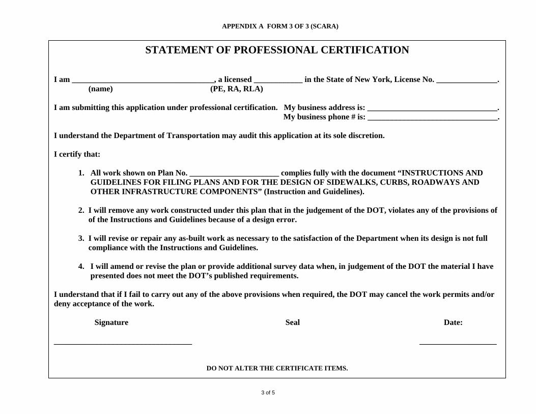
APPENDIX A FORM 3 OF 3 (SCARA)
STATEMENT OF PROFESSIONAL CERTIFICATION
I am ___________________________________, a licensed ____________ in the State of New York, License No. _______________. (name) (PE, RA, RLA) I am submitting this application under professional certification. My business address is: ________________________________. My business phone # is: ________________________________. I understand the Department of Transportation may audit this application at its sole discretion. I certify that:
1. All work shown on Plan No. ______________________ complies fully with the document “INSTRUCTIONS AND GUIDELINES FOR FILING PLANS AND FOR THE DESIGN OF SIDEWALKS, CURBS, ROADWAYS AND OTHER INFRASTRUCTURE COMPONENTS” (Instruction and Guidelines).
2. I will remove any work constructed under this plan that in the judgement of the DOT, violates any of the provisions of of the Instructions and Guidelines because of a design error. 3. I will revise or repair any as-built work as necessary to the satisfaction of the Department when its design is not full
compliance with the Instructions and Guidelines.
4. I will amend or revise the plan or provide additional survey data when, in judgement of the DOT the material I have presented does not meet the DOT’s published requirements.
I understand that if I fail to carry out any of the above provisions when required, the DOT may cancel the work permits and/or deny acceptance of the work. Signature Seal Date: __________________________________ ___________________
DO NOT ALTER THE CERTIFICATE ITEMS.
3 of 5

Fee Feet Feet Feet Feet
APPENDIX A (SCARA)
PLAN TYPES LOG #_____________________________ A Plan does not have to be to scale. Plan must show: property lines, curb lines, sidewalk width and length, encroachments, street furniture. B Plan must be to scale: drawing 1” = 30’ on 2’x3’ (24”x 36”) and drawings to DOT standard, including DOT drawing symbols- see Appendix F. Plan must show:
block #, lot #, property lines, curb line, sidewalk width and length, encroachments, street furniture. C Plan must be to scale: drawing 1” = 30’ on 2’x3’ (24”x 36”) and drawings to DOT standard, including DOT drawings symbols- see Appendix F. Plan must show
block #, lot #, property lines, curb line, sidewalk width and length, encroachments, street furniture, driveways and existing and relocated layout of utility lines. D Plan must be to scale: drawing 1” = 30’ on 2’x3’ (24”x 36”) and drawings to DOT standard, including DOT drawings symbols- see Appendix F. Plan must show
block #, lot #, property lines, curb line, sidewalk width and length, encroachments, street furniture, driveways, drainage details and cross section showing details of the placement and composition of pavers, mortar bed, base, sub-base and method of installation and construction. In addition, photographs that show existing conditions and are clearly labeled, identifying the location from which the photos were taken and the view (north, south, east, west), must be included.
E Plan must be to scale: drawing 1” = 30’ on 2’x3’ (24”x 36”) and drawings to DOT standard, including DOT drawings symbols- see Appendix F. Plan must show
block #, lot #, property lines, curb line, sidewalk width and length, encroachments, street furniture and elevations from curb to first floor/sidewalk, any slope breaks, grades 25’ of abutting sidewalk. A topographical survey shall be required and shall include all information required by Appendix C in the manner specified there. A preliminary Design & Investigation report (PDI) shall be submitted if previously required (i.e. by DOT or, other agency).
F Scale drawing 1” = 30’ on 2’x3’ (24”x 36”) drawings to DOT standard, including DOT drawing symbols- see Appendix F. Plan must show or include the
following:
1) PLAN VIEW & PROFILE VIEW- Existing and proposed infrastructure conditions in all streets abutting the property line, existing and proposed sewers, basins and manholes, extent of proposed pavement, sidewalk and curb, existing portions of pavements, sidewalks and curbs, profiles along all sides of the proposed improvement of existing grade, legal grade at the property line, curb line and gutter reveal, widths of sidewalks and roadways, both mapped and existing, property frontage/lot lines for which the builder(s) are making an application, adjoining street elevations and location plan area, including elevations at 25 feet and 50 feet past the project limit lines, street address of project, lot and block numbers, names of streets, avenues, lanes, etc. and with whom title is vested, including all information on non-mapped areas, i.e. Tax maps, rights-of-way, prescriptive streets, easements and in-rem properties, all information required by Appendix D (plan view) and Appendix E (profile view) in the manner specified there.
2) LOCATION MAP- A small-scale map showing the location of the property in relation to the block and the surrounding streets shall be shown. The
map shall show the full extent of the block and the alignment of all streets that abut it. The street names shall be shown. The following maps are acceptable for use as a location map: Sanborn map, Tax map, Final Section map, Zoning map (enlarged)
3) TOPOGRAPHICAL SURVEY- A topographical survey shall be required and shall include all information required by Appendix C in the manner
specified there.
4) PRELIMINARY DESIGN & INVESTIGATION REPORT- A preliminary design & investigation report (PDI) shall be submitted if previously required (i.e., by DOT or, other agency)
*Note: Some elements of the plan descriptions stated above must be referenced to various DOT and other governmental publications which provide
more detailed technical information. ------------------------------------------------------------------------------------------------------------------------------------------------------------------------------------------------------------- Plan Type: A B C D E F Fee Schedule: No Fee $35 Filling $2 per Linear $4 per Linear $4 per Linear $8 per Linear
4 of 5

APPENDIX A
CERTIFICATION TYPES
The following is information for specific Certifications Types (1 through 11) which are to be put into DOT block format (“boiler plate”) as per appendix B-4 in the DOT publication “Instructions for Filing Plans and Guidelines for the Design of Sidewalks, Curbs, Roadways and other Infrastructure Components.” The Certification block shall be included on the plan cover sheet as per appendix B-1. If more than one Certification Type is required by the plan, then all information shall be combined into one certification block (see sample of multiple Certification Type block in Appendix B-4). These Certification Types are not to be confused with the “Statement of Professional Certification” which is page 3 of the “Sidewalk, Curb and Roadway Application” (SCARA). 1 Self certify that: Plan meets or exceeds DOT standards and specifications; No change in grade. 2 Self certify that: Plan meets or exceeds DOT standards and specifications; No change in grade; Specification of
the materials used for the sidewalk assembly and the details of construction shall be according to DOT requirements. For special pavers, a sample of the material, size 8” x10” x 2”, with test results on the appropriate DOT form, may be submitted.
3 Self certify that: Plan meets or exceeds DOT standards and specifications; No change in grade; Written
approval from utility company received. 4 Self certify that: Plan meets or exceeds DOT standards and specifications; ADA standards met. 5 Self certify that: Plan meets or exceeds DOT standards and specifications; No change in grade; DOB approval
received. 6 Self certify that: Plan meets or exceeds DOT standards and specifications; No change in grade; DEP approval
received. 7 Self certify that: Plan meets or exceeds DOT standards and specifications; No change in grade; DPR approval
received. 8 Self certify that: Plan meets or exceeds DOT standards and specifications; No change in grade; revocable
consent received. 9 Self certify that: Plan meets or exceeds DOT standards and specifications; No change in grade; revocable
consent received; integrity of existing vault, if any. 10 Self certify that: Plan meets or exceeds DOT standards and specifications; ADA standards met; Highway
Design approval received; if applicable, DEP approval received. 11 Self certify that: Plan meets or exceeds DOT standards and specifications; ADA standards met; Highway
Design approval received; approval received from any other Agency and/or utility company, etc., affected.
5 of 5

1 of 10
2 of 10

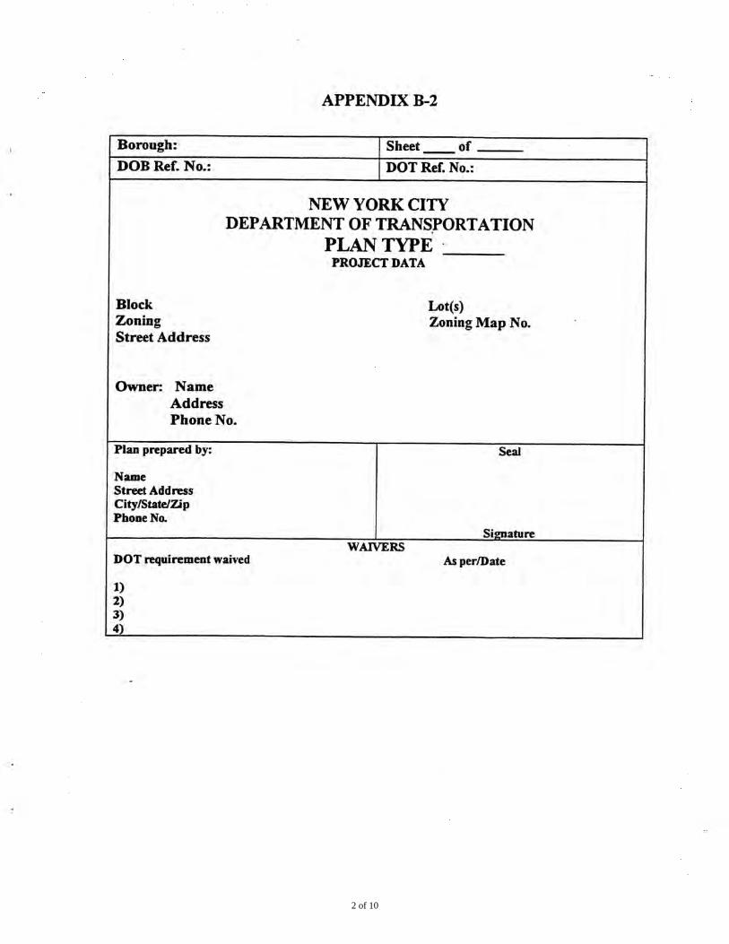
APPENDIX B-3
NOTES GENERAL REQUREMENTS 1. ALL DESIGNS, MATERIALS, CONSTRUCTION METHODS AND WORKMANSHIP SHALL
COMPLY WITH THE FOLLOWING PUBLICATIONS OF THE NEW YORK CITY DEPARMENT OF TRANSPORTATION (DOT): STANDARD SPECIFICATIONS; STANDARD DETAILS OF CONSTRUCTION; RULES OF THE HIGHWAY OPERATIONS; GUIDELINES FOR THE DESIGN OF INFRASTRUCTURE COMPONENTS.
2. ALL NON STANDARD MATERIALS AND CONSTRUCTION PROCEDURES SHALL BE SPECIFICALLY APPROVED IN WRITING BY DOT.
3. ANY WORK NOT COMPLYING WITH THE REQUIREMENTS OF THE DOT SHALL BE REMOVED AND REPLACED.
4. THIS PLAN SHALL BE VALID FOR THE ISSUANCE OF CONSTRUCTION PERMTIS FOR A PERIOD OF ONE YEAR FORM THE DATE OF APPROVAL OR SELF-CERTIFICATION, AS APPLIABLE.
5. ALL SIDEWALK AND STREET AREAS CONSTRUCTED UNDER THIS PLAN SHALL REMAIN OPEN TO THE PUBLIC AT ALL TIMES
ISSUANCE OF PERMITS 6. NO SIDEWALK, CURB OR ROADWAY WORK SHALL BE DONE WITHOUT A PERMIT
FROM THE DOT. THE CONTRACTOR SHALL HAVE ALL REQURED INSURANCE CONVERAGE ON FILE.
7. NO WORK ON DRAINAGE STRUCTURES SHALL BE DONE WITHOUT A PERMIT FROM THE BOUROUGH OFFICE OF THE DEPARTMENT OF ENVIRONMENTAL PROTECTION
8. ANY VAULT WORK AT THE SITE SHALL BE DONE AS PER THE APPLICABLE RULES OF THE DOT AND THE DEPT. OF BUILDINGS.
CONSTRUCTION ACTIVITY 9. A CONSTRUCTION PLAN SHOWING MAINTENACNE AND PROTECTION OF TRAFFIC,
INCLUDING PLACEMENT OF SIDEWALK BRIDGES, BARRIERS AND SIGNAGE SHALL BE SUBMITTED OT THE DOT PERMIT OFFICE BEFORE CONSTURCTION BEGINS.
10. NO SIDEWALK SHALL BE CLOSED WITHOUT A PERMIT. PEDESTRIAN TRAFFIC SAFETY SHALL BE PROTECTED AT ALL TIMES. ROADWAY CLOSINGS SHALL BE AS DIRECTED.
11. THE SITE SHALL BE MAINTAINED IN A CLEAN AND SAFE CONDITION. FINAL SIGN-OFF 12. PERMITS SHALL BE PRESENTED FROM ALL PUBLIC AGENCIES AND UTILITIES
HAVING OWNERSHIP OF STRUCTURES RELOCATED OR REMOVED DURING CONSUTRCITION
13. ALL PAVEMENT MARKINGS INCLUDING THERMOPLASTIC LANE DIVIDERS REMOVED DURING CONSTRUCTION SHALL BE REPLACED IN KIND TO THE DOT STANDARDS.
14. ALL EXISTING CATCH BASINS ON SITE SHALL BE CLEANED AND MADE OPERABLE 15. ALL DAMAGE CAUSED BY CONSTURCTION ON THE PROJECT OUTSIDE THE PROJECT
LIMITS SHALL BE REPAIRED AS DIRECTED. 16. THE ROADWAY SHALL BE PAVED TO THE REQUREMENTS OF THE DOT AND AS
DIRECTED.
3 of 10

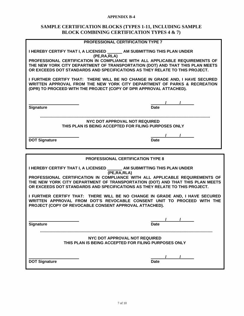
APPENDIX B-4
SAMPLE CERTIFICATION BLOCKS (TYPES 1-11, INCLUDING SAMPLE BLOCK COMBINING CERTIFICATION TYPES 4 & 7)
PROFESSIONAL CERTIFICATION TYPE 1
I HEREBY CERTIFY THAT I, A LICENSED AM SUBMITTING THIS PLAN UNDER (PE,RA,RLA) PROFESSIONAL CERTIFICATION IN COMPLIANCE WITH ALL APPLICABLE REQUIREMENTS OF THE NEW YORK CITY DEPARTMENT OF TRANSPORTATION (DOT) AND THAT THIS PLAN MEETS OR EXCEEDS DOT STANDARDS AND SPECIFICATIONS AS THEY RELATE TO THIS PROJECT. I FURTHER CERTIFY THAT THERE WILL BE NO CHANGE IN GRADE.
/ / Signature Date
NYC DOT APPROVAL NOT REQUIRED THIS PLAN IS BEING ACCEPTED FOR FILING PURPOSES ONLY
/ / DOT Signature Date
PROFESSIONAL CERTIFICATION TYPE 2
I HEREBY CERTIFY THAT I, A LICENSED AM SUBMITTING THIS PLAN UNDER (PE,RA,RLA) PROFESSIONAL CERTIFICATION IN COMPLIANCE WITH ALL APPLICABLE REQUIREMENTS OF THE NEW YORK CITY DEPARTMENT OF TRANSPORTATION (DOT) AND THAT THIS PLAN MEETS OR EXCEEDS DOT STANDARDS AND SPECIFICATIONS AS THEY RELATE TO THIS PROJECT. I FURTHER CERTIFY THAT: THERE WILL BE NO CHANGE IN GRADE AND THAT THE SPECIFICATIONS OF THE MATERIALS USED FOR THE SIDEWALK ASSEMBLY AND THE DETAILS OF CONSTRUCTION SHALL BE ACCORDING TO NYC DOT REQUIREMENTS. (FOR SPECIAL PAVERS, A SAMPLE OF THE MATERIAL, SIZE 8’X10’X2, WITH TEST RESULTS ON THE APPROPRIATE DOT FORM, MAY BE SUBMITTED.)
/ / Signature Date
NYC DOT APPROVAL NOT REQUIRED THIS PLAN IS BEING ACCEPTED FOR FILING PURPOSES ONLY
/ / DOT Signature Date
4 of 10

APPENDIX B-4
SAMPLE CERTIFICATION BLOCKS (TYPES 1-11, INCLUDING SAMPLE BLOCK COMBINING CERTIFICATION TYPES 4 & 7)
PROFESSIONAL CERTIFICATION TYPE 3
I HEREBY CERTIFY THAT I, A LICENSED AM SUBMITTING THIS PLAN UNDER (PE,RA,RLA) PROFESSIONAL CERTIFICATION IN COMPLIANCE WITH ALL APPLICABLE REQUIREMENTS OF THE NEW YORK CITY DEPARTMENT OF TRANSPORTATION (DOT) AND THAT THIS PLAN MEETS OR EXCEEDS DOT STANDARDS AND SPECIFICATIONS AS THEY RELATE TO THIS PROJECT. I FURTHER CERTIFY THAT: THERE WILL BE NO CHANGE IN GRADE, AND I HAVE SECURED WRITTEN APPROVAL TO DO WORK FROM THE APPROPRIATE UTILITY COMPANY (COPY OF APPROVAL DOCUMENT ATTACHED).
/ / Signature Date
NYC DOT APPROVAL NOT REQUIRED THIS PLAN IS BEING ACCEPTED FOR FILING PURPOSES ONLY
/ / DOT Signature Date
PROFESSIONAL CERTIFICATION TYPE 4
I HEREBY CERTIFY THAT I, A LICENSED AM SUBMITTING THIS PLAN UNDER (PE,RA,RLA) PROFESSIONAL CERTIFICATION IN COMPLIANCE WITH ALL APPLICABLE REQUIREMENTS OF THE NEW YORK CITY DEPARTMENT OF TRANSPORTATION (DOT) AND THAT THIS PLAN MEETS OR EXCEEDS DOT STANDARDS AND SPECIFICATIONS AS THEY RELATE TO THIS PROJECT. I FURTHER CERTIFY THAT ALL AMERICANS WITH DISABILITIES ACT (ADA) STANDARDS WILL BE MET. / / Signature Date
NYC DOT APPROVAL NOT REQUIRED THIS PLAN IS BEING ACCEPTED FOR FILING PURPOSES ONLY
/ / DOT Signature Date
5 of 10

APPENDIX B-4
SAMPLE CERTIFICATION BLOCKS (TYPES 1-11, INCLUDING SAMPLE BLOCK COMBINING CERTIFICATION TYPES 4 & 7)
PROFESSIONAL CERTIFICATION TYPE 5
I HEREBY CERTIFY THAT I, A LICENSED AM SUBMITTING THIS PLAN UNDER (PE,RA,RLA) PROFESSIONAL CERTIFICATION IN COMPLIANCE WITH ALL APPLICABLE REQUIREMENTS OF THE NEW YORK CITY DEPARTMENT OF TRANSPORTATION (DOT) AND THAT THIS PLAN MEETS OR EXCEEDS DOT STANDARDS AND SPECIFICATIONS AS THEY RELATE TO THIS PROJECT. I FURTHER CERTIFY THAT: THERE WILL BE NO CHANGE IN GRADE AND, I HAVE SECURED WRITTEN APPROVAL FROM THE NEW YORK CITY DEPARTMENT OF BUILDING (D0B) TO PROCEED WITH THE PROJECT (COPY OF DOB APPROVAL ATTACHED).
/ / Signature Date
NYC DOT APPROVAL NOT REQUIRED THIS PLAN IS BEING ACCEPTED FOR FILING PURPOSES ONLY
/ / DOT Signature Date
PROFESSIONAL CERTIFICATION TYPE 6
I HEREBY CERTIFY THAT I, A LICENSED AM SUBMITTING THIS PLAN UNDER (PE,RA,RLA) PROFESSIONAL CERTIFICATION IN COMPLIANCE WITH ALL APPLICABLE REQUIREMENTS OF THE NEW YORK CITY DEPARTMENT OF TRANSPORTATION (DOT) AND THAT THIS PLAN MEETS OR EXCEEDS DOT STANDARDS AND SPECIFICATIONS AS THEY RELATE TO THIS PROJECT. I FURTHER CERTIFY THAT: THERE WILL BE NO CHANGE IN GRADE AND, I HAVE SECURED WRITTEN APPROVAL FROM THE NEW YORK CITY DEPARTMENT OF ENVIRONMENTAL PROTECTION (DEP) TO PROCEED WITH THE PROJECT (COPY OF DEP APPROVAL ATTACHED).
/ / Signature Date
NYC DOT APPROVAL NOT REQUIRED
THIS PLAN IS BEING ACCEPTED FOR FILING PURPOSES ONLY
/ / DOT Signature Date
6 of 10
APPENDIX B-4
SAMPLE CERTIFICATION BLOCKS (TYPES 1-11, INCLUDING SAMPLE BLOCK COMBINING CERTIFICATION TYPES 4 & 7)
PROFESSIONAL CERTIFICATION TYPE 7
I HEREBY CERTIFY THAT I, A LICENSED AM SUBMITTING THIS PLAN UNDER (PE,RA,RLA) PROFESSIONAL CERTIFICATION IN COMPLIANCE WITH ALL APPLICABLE REQUIREMENTS OF THE NEW YORK CITY DEPARTMENT OF TRANSPORTATION (DOT) AND THAT THIS PLAN MEETS OR EXCEEDS DOT STANDARDS AND SPECIFICATIONS AS THEY RELATE TO THIS PROJECT. I FURTHER CERTIFY THAT: THERE WILL BE NO CHANGE IN GRADE AND, I HAVE SECURED WRITTEN APPROVAL FROM THE NEW YORK CITY DEPARTMENT OF PARKS & RECREATION (DPR) TO PROCEED WITH THE PROJECT (COPY OF DPR APPROVAL ATTACHED).
/ / Signature Date
NYC DOT APPROVAL NOT REQUIRED THIS PLAN IS BEING ACCEPTED FOR FILING PURPOSES ONLY
/ / DOT Signature Date
PROFESSIONAL CERTIFICATION TYPE 8
I HEREBY CERTIFY THAT I, A LICENSED AM SUBMITTING THIS PLAN UNDER (PE,RA,RLA) PROFESSIONAL CERTIFICATION IN COMPLIANCE WITH ALL APPLICABLE REQUIREMENTS OF THE NEW YORK CITY DEPARTMENT OF TRANSPORTATION (DOT) AND THAT THIS PLAN MEETS OR EXCEEDS DOT STANDARDS AND SPECIFICATIONS AS THEY RELATE TO THIS PROJECT. I FURTHER CERTIFY THAT: THERE WILL BE NO CHANGE IN GRADE AND, I HAVE SECURED WRITTEN APPROVAL FROM DOT’S REVOCABLE CONSENT UNIT TO PROCEED WITH THE PROJECT (COPY OF REVOCABLE CONSENT APPROVAL ATTACHED).
/ / Signature Date
NYC DOT APPROVAL NOT REQUIRED THIS PLAN IS BEING ACCEPTED FOR FILING PURPOSES ONLY
/ / DOT Signature Date
7 of 10

APPENDIX B-4
SAMPLE CERTIFICATION BLOCKS (TYPES 1-11, INCLUDING SAMPLE BLOCK COMBINING CERTIFICATION TYPES 4 & 7)
PROFESSIONAL CERTIFICATION TYPE 9
I HEREBY CERTIFY THAT I, A LICENSED AM SUBMITTING THIS PLAN UNDER (PE,RA,RLA) PROFESSIONAL CERTIFICATION IN COMPLIANCE WITH ALL APPLICABLE REQUIREMENTS OF THE NEW YORK CITY DEPARTMENT OF TRANSPORTATION (DOT) AND THAT THIS PLAN MEETS OR EXCEEDS DOT STANDARDS AND SPECIFICATIONS AS THEY RELATE TO THIS PROJECT. I FURTHER CERTIFY THAT: THERE WILL BE NO CHANGE IN GRADE, AND I HAVE SECURED WRITTEN APPROVAL FROM DOT’S REVOCABLE CONSENT UNIT TO PROCEED WITH THE PROJECT (COPY OF REVOCABLE CONSENT APPROVAL ATTACHED). IN ADDITION, I CERTIFY THAT IF A VAULT EXISTS AT THE LOCATION, THE PROPOSED STRUCTURE WILL NOT IN ANY WAY, DO STRUCTURAL DAMAGE TO THE VAULT.
/ / Signature Date
NYC DOT APPROVAL NOT REQUIRED THIS PLAN IS BEING ACCEPTED FOR FILING PURPOSES ONLY
/ / DOT Signature Date
PROFESSIONAL CERTIFICATION TYPE 10
I HEREBY CERTIFY THAT I, A LICENSED AM SUBMITTING THIS PLAN UNDER (PE,RA,RLA) PROFESSIONAL CERTIFICATION IN COMPLIANCE WITH ALL APPLICABLE REQUIREMENTS OF THE NEW YORK CITY DEPARTMENT OF TRANSPORTATION (DOT) AND THAT THIS PLAN MEETS OR EXCEEDS DOT STANDARDS AND SPECIFICATIONS AS THEY RELATE TO THIS PROJECT. I FURTHER CERTIFY THAT: I HAVE SECURED WRITTEN APPROVAL FROM THE NEW YORK CITY DEPARTMENT OF ENVIRONMENTAL PROTECTION (DEP) AND IF APPLICABLE, DOT’S HIGHWAY DESIGN TO PROCEED WITH THE PROJECT (COPY OF DEP AND HIGHWAY DESIGN APPROVAL ATTACHED); AND, ALL AMERICANS WITH DISABILITIES ACT (ADA) STANDARDS WILL BE MET.
/ / Signature Date
NYC DOT APPROVAL NOT REQUIRED THIS PLAN IS BEING ACCEPTED FOR FILING PURPOSES ONLY
/ / DOT Signature Date
8 of 10

APPENDIX B-4
SAMPLE CERTIFICATION BLOCKS (TYPES 1-11, INCLUDING SAMPLE BLOCK COMBINING CERTIFICATION TYPES 4 & 7)
PROFESSIONAL CERTIFICATION TYPE 11
I HEREBY CERTIFY THAT I, A LICENSED AM SUBMITTING THIS PLAN UNDER (PE,RA,RLA) PROFESSIONAL CERTIFICATION IN COMPLIANCE WITH ALL APPLICABLE REQUIREMENTS OF THE NEW YORK CITY DEPARTMENT OF TRANSPORTATION (DOT) AND THAT THIS PLAN MEETS OR EXCEEDS DOT STANDARDS AND SPECIFICATIONS AS THEY RELATE TO THIS PROJECT. I FURTHER CERTIFY THAT: I HAVE SECURED WRITTEN APPROVAL FROM DOT’S HIGHWAY DESIGN TO PROCEED WITH THE PROJECT AND ANY AFFECTED NEW YORK CITY AGENCY AND/OR UTILITY COMPANY (COPY OF ALL APPROPRIATE APPROVALS ATTACHED); AND, ALL AMERICANS WITH DISABILITIES ACT (ADA) STANDARDS WILL BE MET.
/ / Signature Date NYC DOT APPROVAL NOT REQUIRED
THIS PLAN IS BEING ACCEPTED FOR FILING PURPOSES ONLY
/ / DOT Signature Date
PROFESSIONAL CERTIFICATION TYPE 4 & 7
I HEREBY CERTIFY THAT I, A LICENSED AM SUBMITTING THIS PLAN UNDER (PE,RA,RLA) PROFESSIONAL CERTIFICATION IN COMPLIANCE WITH ALL APPLICABLE REQUIREMENTS OF THE NEW YORK CITY DEPARTMENT OF TRANSPORTATION (DOT) AND THAT THIS PLAN MEETS OR EXCEEDS DOT STANDARDS AND SPECIFICATIONS AS THEY RELATE TO THIS PROJECT. I FURTHER CERTIFY THAT: THERE WILL BE NO CHANGE IN GRADE, ALL AMERICANS WITH DISABILITIES ACT (ADA) STANDARDS WILL BE MET, AND I HAVE SECURED WRITTEN APPROVAL FROM THE NEW YORK CITY DEPARTMENT OF PARKS & RECREATION (DPR) TO PROCEED WITH THE PROJECT (COPY OF DPR APPROVAL ATTACHED).
/ / Signature Date
NYC DOT APPROVAL NOT REQUIRED THIS PLAN IS BEING ACCEPTED FOR FILING PURPOSES ONLY
/ / DOT Signature Date
9 of 10

APPENDIX B-5 & B-6
APPENDIX B-5
DOT APPROVAL OF DESIGN ELEMENTS For self-certified projects only
Item requiring DOT approval Approved by Date
APPENDIX B-6
LIST OF ESTIMATED QUANTITIES New Curb Lin. ft. New Sidewalk Sq. ft. New Roadway Sq. yds. New Trees Each New CBs Each New DIP Lin. ft. New Manholes Each
10 of 10

APPENDIX C
REQUIREMENTS FOR PREPARING A TOPOGRAHICAL SURVEY
A) The Topographic Survey shall cover the area abutting the site within the public right-of-
way from property line to property line, and the area extending 50 feet beyond any mid-block lot lines of the property.
B) The Topographic Survey shall be referenced by station and offset to a Center Line
Baseline of the Mapped Street which has been established/coordinated/tied into existing Borough Monument Lines, in accordance with current Departmental Standards. All elevations shall be referenced to established Borough Bench Marks, or to bench marks set from said Borough Bench Marks, through the use of independent Bench Runs. The reference points including bench marks and turning points for the independent bench runs and all tie-ins to the Center Line baseline shall be clearly documented so that any other surveyor may reestablish them in the future.
The Topographic Survey shall locate all physical features within the project limits needed to produce a comprehensive design, including, but not limited to, the following information:
a) Established building line lengths, including interior angles. b) Established legal grades of all streets. c) Legal widths from property line to property line. d) Identification of “possession” lines where different from property lines. e) Actual widths of all pavements, sidewalks and sidewalk areas. f) Identification of all streets, including “paper” streets, by name. g) Identification of all plazas, malls and public areas. h) Location by station and offset of all roadways, edges of pavements, headers,
curbs, curb cuts, pedestrian ramps, sidewalks, driveways, distinctive/special sidewalk areas, bus stops, traffic islands and traffic channelization (permanent and temporary), trees (including caliper and edge distance to existing curb), wooded areas and survey monuments. Existing curbs, sidewalks and pavements shall be identified by condition and type of material.
i) Location by station and offset, and identification of all street hardware including,
but not limited to, valve box cover castings, manhole cover castings, catch basins, inlets, utility chamber covers, gratings and headwalls.
j) Location, by station and offset, and identification of all sidewalk hardware
including but not limited to, coal chutes, oil fills, cellar doors, undersidewalk drains, sidewalk elevators, building sidewalk ventilation gratings, subway ventilation gratings, hydrants (high pressure, low pressure), street lights, traffic signal poles, parking signs, parking meters, traffic control boxes, traffic
1 of 3

APPENDIX C
REQUIREMENTS FOR PREPARING A TOPOGRAHICAL SURVEY
controllers, traffic detectors, fire call boxes, police call boxes, subway entrances and emergency exits, traffic stanchions, structural columns, monuments, newsstand kiosks, sidewalk retail areas, areaways, decorative fences and railings, steps, walls, stoops, planting areas, railroad gates, trackage and cellar windows at grade.
k) The probable existence, extent and impact of undersidewalk vaults shall be ascertained through the use of a record search and visual surface inspection. All data shall be incorporated into the Topographic Survey.
l) Location, by station and offset, of all columns and abutments for all grade
separation structures, pedestrian overpasses, and vehicular/railroad structures.
m) Location, by station and offset, of all street encroachments including, but not limited to, hedges, fences, grass areas, retaining walls, rock outcrops, steps and stoops.
n) Location, by station and offset, of all surface drainage elements including, but
not limited to, swales/ditches, brooks/creeks, streams/channels, water courses, retention areas, headwalls, swamp areas and other drainage structures or appurtenances.
o) Location and identification of all abutting tax lots by Lot and Block Numbers
(including those encroaching into the mapped right-of-way), as well as existing frontage lengths.
p) Location, by station and offset, of all abutting buildings, including identification
by house numbers, story height, entranceways, building type and use.
q) Direction of traffic, and the location and type of all lane and crosswalk markings, including school crossing markings.
C) Horizontal locations shall be taken to the nearest tenth (1/10) of a foot. D) Vertical locations (elevations) shall be taken to the nearest hundredth (1/100) of a foot
longitudinally at 25 foot stations (50′ stations of virgin streets and complete reconstructions), as measured along the Center Line Baseline, and at all street intersections (P.T.’s, property lines and centerline of intersecting streets), breaks in grade, building lines at intersections, and other locations required to fully define the existing topography; transversely, elevations shall be taken at the building lines, top and bottom of curbs, center line of street, front and back edges of ribbon sidewalks, and widening line(s), where applicable
E) Spot elevations shall be taken at all street surface hardware locations, steps/platforms,
building entrances, first floors, garage floors, back of sidewalk at all entranceways, ground elevations at building entrances, traffic islands, driveways, parking aprons, intersections (as required), corner (with crosswalk) sidewalk quadrants, storm/combined sewer inverts, at points giving the clearance from the roadway to the underside of overhead structures, Transit Authority ventilator structures and as otherwise required for design.
2 of 3

APPENDIX C
REQUIREMENTS FOR PREPARING A TOPOGRAHICAL SURVEY F) Spot elevations shall be taken at the centerline of all existing trees, as follows: top of curb
in front of tree, average root zone elevations nearest curb, top of sidewalk at front edge and at back edge.
G) Datum Plane and Coordinate System shall be “as in use” by the respective Borough
Presidents Office. Where no City coordinate system exists, the surveyor, upon written authorization from DOT, may utilize an independent coordinate system.
H) All measurements shall be in the United States Standard of Measurements. I) Flat or reverse sidewalk pitch at a lot line. When the elevation at the property line is
equal to or below that of the top of curb, the survey shall include elevations of the top of curb and property line at 5’ and 10’ beyond the lot line.
J) Legal Grade for the site shall be based on the grades shown on the final section map on
file in the topographic section in the Borough President’s Office. The Surveyor shall calculate the Legal Grade for the project using the Legal Grades shown on the map and the gradients based on the distances between the grades shown. The Legal Grades for the site shall be referenced as follows: Borough Legal Grade refers to Manhattan Top of Curb Bronx Top of Curb Brooklyn Top of Curb Staten Island Top of Curb Queens Centerline of street
3 of 3

APPENDIX D
INSTRUCTIONS FOR PREPARING PLAN VIEWS
A) Each plan view shall depict, to scale, the area within the right-of-way lines plus an area within the owner’s property at least 40’ deep. The view shall also depict the area adjacent to the owner’s property for a distance of 50’, or across the intersection, as applicable.
B) Scale: 1”=20’ or larger i) Virgin streets: 1”=30’ permitted
C) The plan view shall present the information about the property frontage and
its immediate vicinity collected by the surveyor as per Appendix B of this booklet. This includes the R.O.W. lines, property, possession and lot lines, edges of pavement, sidewalks, planted areas, areas of distinctive pavement, unpaved areas, curb cuts, handicap ramps, steps, stoops, structures, encroachments, street and sidewalk hardware, sewers, trees and other physical features required to accurately depict the site.
D) The plan view shall also show all proposed installations, including the lines of
new sidewalks and curbs and the extent of new pavement. Areas of cut and fill adjacent to the new work shall be shown and the slopes called out.
E) Within the minimum 40’ deep area of the owner’s property, the following
shall be shown: Building footprints, retaining walls, driveways, parking lots, walkways, stairs, significant slopes, large trees and other items at the R.O.W. line that may impact the installations within the roadway.
F) Dimensions. All dimensions required to construct the new work and to define
the exact location of existing conditions shall be shown, including property line lengths, widths of sidewalk, widths of driveways, widths of streets and paved areas, etc. Dimensions shall be shown correct to two decimal places.
G) Stationing. Each plan view shall be stationed as follows: A baseline shall be
established, generally along the centerline, and key features of the site shall be defined by perpendicular offsets from the centerline to the property line. The stationing of the following points shall be called out on the plan: property/lot lines, PC/PT at corners, and other features of special significance to the design such as points of Legal Grade change, etc. The baselines shall show stations at 50’ intervals. All stations shall be accurate to two decimal places.
H) Vertical elevations.
i) Option 1: The plan views shall show the construction grades for all new installations as follows: a) The following grades shall be shown: Property line or back of
sidewalk, as applicable/top of curb/bottom of curb/roadway centerline.

APPENDIX D
INSTRUCTIONS FOR PREPARING PLAN VIEWS
b) The design elevations shall be shown correct to two decimal places immediately adjacent to a tick mark indicating the location of the grade.
c) The design grades shall be shown only at the following points: Midblock lot lines/breaks in grade/PC-PT. The station of all grade breaks shall be given.
d) The station and offset of each elevation shown on the plan shall be apparent from the plan.
ii) Option 2: To save time and labor, the designer of the plan may elect to
omit showing any design elevations on the plan view. Under this option the design grades shall appear only in the profile views. In this case, the profiles shall be prepared in strict accordance with the requirements of Appendix F.
iii) Rim/grate and invert elevations of all sewer structures shall be shown on
all plan views.
I) Descriptions and labels of proposed and existing installations
i) For items depicted using the standard DOT Division of Roadway Engineering symbols, no other written descriptions or labels shall be used.
ii) Curbs and sidewalks shall be identified with concise labels only, using
abbreviations where applicable (e.g. New conc. Walk, New steel curb, Exist. conc. curb, etc.)
J) Street status. The legal status of all streets abutting the site shall be described on the
plan, based upon information available from the topographic bureau of the Borough President’s Office.


1 of 5

2 of 5

3 of 5

4 of 5
5 of 5

1 of 9

2 of 9

3 of 9

4 of 9
5 of 9

6 of 9

7 of 9

8 of 9

9 of 9

GLOSSARY OF HIGHWAY ENGINEERING TERMS Stationing. This is a method of keeping accurate track of the distance of any point from a reference point, or of the point from any other point. Such information is crucial because, in highway design, distances and grades cannot be approximate or unclear. For instance, a vertical difference of one inch in 30 feet may seem insignificant, but in fact this represents the difference between an acceptable roadway drainage slope and a flat one, where water will not drain, and which is obviously not allowed. The method of stationing is used to assure precise horizontal measurement. It works as follows: A starting point is arbitrarily chosen (generally, one that makes sense). A straight line (the baseline) is projected from this point in a given direction. Distances are marked off in 100-foot lengths (“stations”), starting from point 0 + 00. The 100-foot mark becomes 1 + 00, the 200-foot mark is 2 + 00, etc. Intermediate points are referenced as, say, 0 + 38.9 (at the 38.9 foot mark), 1 + 79.23 (at the 170.23 foot mark), etc.
When the location of any given point on a project is wanted, it is determined as follows: A line is shot, perpendicular to the baseline, from the baseline to the point. The station at which the perpendicular crosses the baseline, and the length of the offset from the baseline to the point, become the coordinates of the point in question. (When the distance between two points not on the same baseline is wanted, more elaborate calculations may be needed, depending on the geometry of the road alignment.)
One major benefit of using the station system is that it eliminates the need to use architectural dimension line, greatly uncluttering the plan view.
For stationing to be used correctly, it’s essential that the location of every vertical elevation on the plan be specified correctly. This requires that the exact place where the surveyor took every elevation shown on the survey be known. A survey on which the distance between individual surveying shots is not clearly specified, or obvious, cannot be used to prepare a Plan Type F.
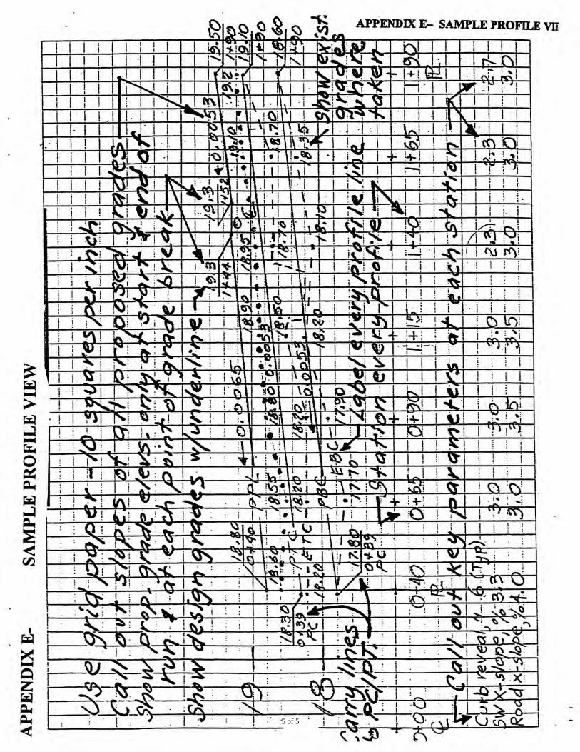
Profiles. A profile is a line that represents the elevation of the ground surface in a
defined direction. The profiles used in a Plan Type F depict the elevation of the surfaces at the back of the sidewalk (PL), top of curb (TC), bottom of curb (BC), and street centerline (CL). These lines, when plotted on grid paper at a greatly exaggerated scale, permit the Plan Type F examiner to be sure the geometric design of the curb, sidewalk and roadway meets standards. The profiles are a graphic device and are interpreted visually by the examiner, who studies the relationships among the lines to check the various slopes at the site.
For this reason, we require that the various elevations be plotted completely accurately, and that the accuracy be easy to verify. This is the reason we insist on grid paper, which is designed for easy plotting and checking. Careless plotting distorts the shape of the profile, leading the examiner to make erroneous decisions about the acceptability or safety of a design. Since these decisions affect the liability of the City in case of an accident, properly drawn profiles are crucially important to us.
Plotting the profiles is not difficult, once the concept is understood. To facilitate the construction of profiles, grid paper is commonly used. This has horizontal and vertical lines in pale green, blue or orange, so spaced as to represent certain distances in the horizontal and vertical scales. Paper divided into one-inch squares by fairly heavy
1 of 3
GLOSSARY OF HIGHWAY ENGINEERING TERMS lines is common. The spaces between two such horizontal and vertical lines are divided into 10 equal parts by lighter lines. To accentuate the differences of elevation, the space between two horizontal lines is considered as equivalent to 0.1 feet or 0.05 feet, and the space between two heavy vertical lines is considered as equivalent to 8, 10, 16 or 20 feet, according to the total difference of elevation, the amount of vertical exaggeration desired, the length of the line, and the requirements of the work.
The elevation of some convenient horizontal line is assumed, and one of the vertical lines is taken as station 0 + 00. As the elevation or station of each printed line is known, the points on the ground surface can be plotted easily. When these points are connected with a smooth line, an accurate representation of the ground surface should result.
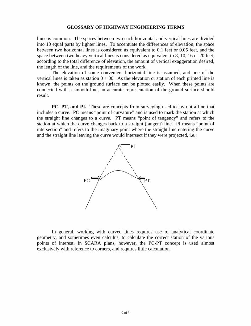
PC, PT, and PI. These are concepts from surveying used to lay out a line that
includes a curve. PC means “point of curvature” and is used to mark the station at which the straight line changes to a curve. PT means “point of tangency” and refers to the station at which the curve changes back to a straight (tangent) line. PI means “point of intersection” and refers to the imaginary point where the straight line entering the curve and the straight line leaving the curve would intersect if they were projected, i.e.:
PI
PC PT
In general, working with curved lines requires use of analytical coordinate
geometry, and sometimes even calculus, to calculate the correct station of the various points of interest. In SCARA plans, however, the PC-PT concept is used almost exclusively with reference to corners, and requires little calculation.
2 of 3

3 of 3

1 of 3

APPENDIXH
very desirable roadway symmetrythat should be retained. A symmetricalroadway crosssection isalways easier to work with from a roadway design point of'view, especiallywhen theDOT rehabilitates roads using the methodknown as "engineered resurfacing." In general, youshould not set a TC elevation so that it damages any existing symmetry.
3) What's the extentofyourproject?Ifit's 40' or less, things become fairly simple. In general, with a project oflimited
frontage, especially in a built-up area, the curb reveal will be dictated by the curb height ateither end ofyour lot. One complication may occur ifyou have a dropped curb at the lot line.In such a case, ofcourse, you must meet the existing driveway without any trip hazard. Butthe curb reveal immediately beforethe driveway should match the full-height revealimmediately beyond the driveway on the neighbors property.
As a general rule, except inundeveloped or deteriorated areas, you should not raise orlower your top ofcurb immediately adjacent to your lot lines simply to achieve what youbelieve is some "correct" curb height. Whenever you raise a curb top, you're simultaneouslyraising the entire sidewalk slab, and that can have a significanteffect on pedestrians.
4) Was the existing curb built by the City under a major r~onstruetionproject?If it was, you should probably retain the existing top ofcurb elevations.5) What's the infrastructure like in your neighborrhood?In many parts ofNew York, the existing streets and sidewalks were designed with
great skill and intelligence by the city'smunicipal engineers. In other pans ofthe city, theinfrastructure has deteriorated, or was installed piecemeal by private developers without muchengineering oversight.. Whenyou havea project in a neighborhood that was properlydesigned and maintained, you should generally put the new curb in to the existing elevations.(If the curb is very shallow, it's almost always because of repeated resurfacings. There can be asurprising thickness of extra asphalt on some streets.) The trick is to recognize whether theinfrastructure has been designed and kept up properly. Walkthe adjacent blocks and look atthe curbsand sidewalks. Look at the roadway crown and curb reveals. Is the workconsistent? Does it seem to fit effortlessly? Does it provide you with a smooth, safe passage?
6) How high is the curb reveal in your immediate neighborhood? Is it consistent?In fully built-up neighborhoods, if the curb reveal is consistent, your new curb should
probablybe set to that height - even ifit's very shallow. (First, however,.investigate loweringthe pavement to increase the reveal-- see below.) On manystreets on the Upper East Side ofManhattan, for instance, the existing curbs are all 2n high. This is not reallydesirablefrom asafety point ofview, but it would be a serious error to try anddesign a "6" curb in such aneighborhood. In fact, -on somestreets on the East Side the existing curbs are all 1n deep.Again, that's often what a new curb in such a neighborhood should be. (One exception: -Ifthere's a significantponding problem.) But in a neighborhood that is currently beingredeveloped, as in pans ofthe Bronx, for instance, where the infrastructure has deteriorated, "matching an existing 1" reveal probably would not be appropriate.
Before being forced to accept a substandard reveal, however, see whether you can dropthe pavement. This is a process involving very precise design calculations.. But it can only bedone if the roadway has more than a 1% longitudinal slope, and ifthe cross-slope is not toosteep.
7) What's the existing topography of the land like?Ifthe underlying street bed is flat in the transverse direction (looking across the street),
the top ofcurb elevations should ideally be the "same on each side ofthe street.
2 of 3

.APPENDIXH
Ifthe land is sloping in the transverse direction, you must look at how the street wasdesigned. There are two possibilities:
Case 1 Case2
In Case 1, a symmetrical street bed hasbeen carved out ofthe sloping hillside. In thiscase, the top ofcurb elevations should ideally be the same on both sides ofthe street.
In case 2, a non-symmetric street bed has been designed, with one top ofcurb at asignificantly different elevation from the opposite top ofcurb. This type ofcase complicatesthe roadway design. In general, no top ofcurb elevation should be set that increases theimbalance between the two sides.
8) What is the existing geometry ofthe street?No curb should be designed without looking at the curb reveal across the street andthe
roadway cross slope on each side ofthe street. Ifthe cross slope on your side is inadequate,you may be required to deal with that, and it may affect your curb reveal. In general, you don'twant to design a sizeable curb reveal on your side ifthe one across the street is verysubstandard The point is to avoid designing a curb that will cause problems when the DOTremoves the old asphalt and resurfaces the roadway. One very good way to check a proposeddesign is as follows: In section, draw in your proposed top and bottom ofcurb, the existingcenterline elevation, and the existing top and bottom ofcurb directlyacross the street. Now,imagine that each curb will be 7" deep, and draw in a roadway surfaceto accommodate thesecurbs. Check that the resulting cross slopes will be within our allowable parameters. For
example: /PTC E,;( f /Ex. TC~.Y
L?BC r : 1/'.
___' cx .8C7
/ 1 ~~
/,,-dl
I .~ {e ~-~; 7 11
~.A
1 J~.PreP" ./ r ' .R~ :-:' f/'7~.:?CI/?q .
'- .......... -"
In this example, the proposed design would not be acceptable because,with it, aproper crosssectioncould not be achieved if the DOT resurfaced the street.
9) What is the Legal Grade?If the Legal Grade at the site is within inches of the existing top of curb elevations, you
must discuss the matter with your plan examiner. IfLG is further away, and you're in a builtup area, LG will usually not be a factor in your design.
3 of 3

1 of 4

2 of 4

3 of 4

4 of 4

NEW YORK CITY DEPARTMENT OF TRANSPORTATION
BUREAU OF PERMIT MANAGEMENT AND CONSTRUCTION CONTROL
DISTINCTIVE SIDEWALK
GENERAL INFORMATION: The New York City Department of Transportation (DOT) will permit a property owner (owner) to install a distinctive sidewalk fronting their property provided that the following criteria are met:
The owner (or designated representative) submits the required DOT filings and applicable fee to DOT as specified below
The Public Design Commission approves the design The owner complies with the insurance requirements as per the Distinctive
Sidewalk Improvement Maintenance Agreement (Agreement) The proposed material meets certain physical requirements as specified below
DEFINITION: A distinctive sidewalk is any sidewalk that is not:
Standard concrete/standard color Scored in panels of 5' x 5' Built with joints perpendicular and parallel to the curb
REQUIRED FILINGS & FEES: The property owner must engage an architect, engineer, surveyor or landscape architect licensed by New York State to process the request. The licensed professional must file the following applications and plans following the guidelines and procedures established by, and available from, the New York City Department of Transportation:
The Sidewalk, Curb & Roadway Application (SCARA) The correct Plan Type based on SCARA The Distinctive Sidewalk Paving Material & Test Report Form- see Attachment 1
Additionally, the owner (or designated representative) must file with DOT: The Distinctive Sidewalk Improvement Maintenance Agreement (Agreement) The current filing fee based on the linear feet of the proposed distinctive sidewalk All filings & fees shall be submitted to:
New York City Department of Transportation Bureau of Permit Management & Construction Control
55 Water St, Concourse Level New York, NY 10041
Attn: Distinctive Sidewalk/Plan Examination
1 of 11

TECHNICAL REQUIREMENTS:
For Paving Stones, Bricks, etc.: * Minimum thickness 2” * Substrate 4"/7" concrete on 6" cinder/gravel base * Setting bed and joint treatment: DOT approval required * Finish: Slip-resistant- see below and Attachment 2 * Physical characteristics- see Attachment 3
For Distinctive Scored or Colored Concrete:
* Color or other additives: DOT approval required * Finish: Wood float or light broom * Panel separators: DOT approval required
PUBLIC DESIGN COMMISSION APPROVAL: DOT will submit plans to the Public Design Commission for approval. No plans will receive final DOT approval without the approval of the Public Design Commission.
A. DOT Design Review and Pre-Application
1. Prospective applicants will be instructed to contact DOT’s Director of Design Review (DDR), who is the liaison to the PDC. The DDR will advise the applicant to review DOT’s Street Design Manual that includes the current materials palette and is available on DOT’s website. The DDR will also review with the applicant the on-line PDC guidelines, which generally discourage the installation of distinctive sidewalks and endorse the use of consistent materials on most streets. Designs for distinctive sidewalks that are part of new building construction projects will be referred to and coordinated with the staff of the New York City Department of Buildings.
2. In order to be considered for a distinctive sidewalk, an application must
meet one of these criteria:
(a) encompass an entire block; pertain to a streetscape project; (b) relate to a landmark designated by the New York City Landmarks
Preservation Commission (LPC); or (c) feature a design integral to a building or open space that
significantly enhances the public realm. Applications that do not meet these criteria will not advance to the PDC for conceptual review and the DDR will notify the applicants of this determination in writing.
2 of 11

3. Upon review of an application that satisfies one of the above referenced
criteria, the DDR will arrange a pre-application meeting with the applicant to review the design for context and site appropriateness, consistency with neighboring street materials and treatments, and overall design suitability. If the proposal is not consistent with DOT’s Street Design Manual, does not meet the PDC guidelines, or does not exhibit satisfactory design integrity as outlined above, the DDR may request revisions and design alternatives.
4. If the application meets the aforementioned guidelines, the applicant will be notified in writing by the DDR that DOT has accepted the distinctive sidewalk application for PDC conceptual review.
B. PDC Conceptual Review
1. Upon notification that DOT has accepted the application for PDC conceptual review, the applicant will coordinate with the DDR to prepare a formal proposal to the PDC for conceptual review in accordance with the PDC guidelines.
2. Applicants who are granted conceptual approval may have to address
and/or incorporate comments made by the PDC into their proposed design. Accordingly, the applicant will work with the DDR to execute any necessary changes to the proposed design.
3. If the PDC denies conceptual approval, the project will not move forward
to Sidewalk, Curb and Roadway Application (SCARA) review. C. Sidewalk, Curb and Roadway Application (SCARA) Review
1. If conceptual approval is granted by the PDC, the DDR will notify DOT’s Office of Construction Mitigation and Coordination, Street Pavement Section (OCMC) in writing of such approval and will instruct the applicant to prepare and submit a SCARA to OCMC.
2. OCMC will review the application and notify the DDR in writing of its
determination.
3. The DDR will notify the applicant in writing of OCMC’s approval of the SCARA. The applicant must execute and comply with the current version of DOT’s Distinctive Sidewalk Improvement Maintenance Agreement (DSIM Agreement) before DOT grants its final approval.
3 of 11

4. Upon receipt of the SCARA approval, the applicant will be instructed by the DDR to resubmit the application to the PDC for preliminary and final review.
D. PDC Preliminary and Final Review
1. The applicant will submit a copy of the SCARA approval along with the requisite PDC submission materials.
2. The applicant will coordinate with the DDR to execute any necessary
changes to the proposed design resulting from PDC staff-level and committee reviews and as requested by the PDC at its public meeting/hearing.
3. If the application receives final PDC approval and certification, the DDR
will notify OCMC in writing and instruct the applicant to obtain all necessary permits and approvals, including but not limited to DOT construction permits.
E. Applications Involving Revocable Consents
1. If the applicant proposes to install an aboveground or underground structure in addition to the distinctive sidewalk, the DDR will refer the application to the DOT Division of Franchises, Concessions and Consents (FCC) before it is accepted for PDC conceptual review. The applicant may be instructed to submit a petition for a revocable consent as set forth in Title 34, Chapter 7 of the Rules of the City of New York.
2. Distinctive sidewalks and revocable consents are subject to different
requirements and separate review procedures. However, all presentations to the PDC (conceptual, preliminary, and final) must include both types of proposed streetscape element. The DDR and FCC will coordinate to ensure that both sets of requirements are met before submission to PDC.
3. The revocable consent will not be granted by FCC until the applicant’s
SCARA is approved and the application receives final PDC approval and certification.
LEGAL AGREEMENT: The property owner (or designated representative) must sign four copies of the current version of DOT’s Distinctive Sidewalk Improvement Maintenance Agreement (Agreement) before DOT will accept the plan. The Agreement shall not be altered or retyped. PROCESSING THE AGREEMENT: After all the copies of the Agreement are co-signed by DOT, one copy will be returned to the owner. This copy must be filed and indexed with the City Register or County Clerk for the borough where the property is
4 of 11

located. Upon presentation of proof of filing, the finished sidewalk will be inspected by DOT for compliance with the accepted plan. After the new sidewalk passes DOT inspection, a copy of the Agreement containing DOT’s approval will be given to the property owner. If the new sidewalk fails to comply with the DOT accepted plan, the owner must have the non-complying work repaired or removed and replaced correctly before DOT will acknowledge final acceptance. INSURANCE: The property owner must comply with the requirements of Section 12 of the legal Agreement before the plan will be accepted. A sample certificate of insurance is attached for reference- see Attachment 4. SLIP RESISTANCE: All materials used for distinctive sidewalks shall comply with the recommendations for slip resistance of the United States Architectural & Transportation Barriers Compliance Board, issued in conjunction with the passage of the Americans with Disabilities Act (ADA). These recommendations call for a coefficient of static friction of 0.6 for level areas and 0.8 for ramps. To demonstrate compliance, the applicant shall submit test results from a licensed testing laboratory. The laboratory may use the NBS-Brungraber Tester or the Horizontal Pull Slipmeter, as described in the Compliance Board publication "Slip Resistant Surfaces Advisory Guidelines"- see Attachment 2. Or the laboratory may use the American Society for Testing and Materials (ASTM) Test C1028. In all cases, the proposed paving material must be tested under both wet and dry conditions using both Neolite and leather (ASTM standard) soles. If the material fails the required test, the surface may be altered to increase slip resistance. The altered material must be re-tested and the new test results must be submitted. SAMPLE: In some cases, the applicant may be required to submit an original sample size or a minimum sample size of about 8" X 10" with 2" thickness. This determination shall be made by DOT on a case by case basis. BOILERPLATE: The following note should be completed and put on the plan: Repairs and Maintenance of the sidewalks to be constructed with the following distinctive materials ( ), bounding the property with street address ( ) shall be in accordance with the Distinctive Sidewalk Improvement Maintenance Agreement signed on date ( ) and filed with the Department of Transportation, Bureau of Permit Management and Construction Control and all other Applicable Agreements between the City of New York and the owners.
5 of 11

New York City Department of Transportation
Distinctive Sidewalk Paving Material & Test Report Form
Applicant’s Name: Job Location: Plan #: Block #: Lot #: Sample Type: Sample Finish: Sample Size: Source: Date Sample Submitted: Date Tested:
TEST REPORT
Slip Resistance or Coefficient of Static Friction
Crushing Strength (psi)
ASTM
Breaking Strength (psi)
ASTM
Abrasion Resistance
ASTM Dry Condition Wet Condition
The above test results comply fully with the Special Street Pavement requirements of the New York City Department of Transportation1
Date Signature (P.E., R.A., L.S., or R.L.A.) Seal
1 Note: A Manufacturer’s Certificate or Test Report from a Licensed Testing Laboratory shall be submitted to demonstrate compliance.
6 of 11

HOW IS SLIP RESISTANCE MEASURED? From “Slip Resistant Advisory Guidelines”
A variety of devices are available for measuring slip resistance. In a recent study
conducted at The Pennsylvania State University three slip resistance testers– the NBS- Brungraber Tester, the Horizontal Pull Slipmeter, and the PTI (Pennsylvania Transportation Institute) Drag Sled Tester -- were evaluated. All three devices are portable and easy to use. The following major criteria were applied in the evaluation study: Relevance- The measuring results should correlate in a known and constant manner with human perception of the surface slipperiness. Versatility- Accurate measurements of slip resistance must be possible on various types of surfaces (smooth, rough, level, inclined) and under diverse conditions (wetness, contaminated). Sensitivity to measuring technique- the difference between measurements performed on the same surface and under the same conditions by different persons should be minimal. In addition, reliability, repeatability, and precision of the testers were determined. Reliability was evaluated on the basis of hardware failures recorded during the testing program. Repeatability was determined by the scatter of measuring results from experiments conducted several times on the same surface and under the same test conditions but distributed over a significant period of time. Precision is measured by the scatter of a series of successive reading obtained on a given surface over a short period of time. Based on the results of this study, the NBS- Brungraber Tester was recommended as the best device currently available for measuring slip resistance. The NBS- Brungraber Tester is portable and very easy to use. The measuring procedure described in the tester manual can be mastered in 30 minutes. The tester measures the static coefficient of friction between a representative sample of shoe sole material and a flooring surface. The result from the recording shaft is converted into an equivalent value of static coefficient of friction by means of the calibration chart or formula supplied with the tester.
(1) A B
(3) A B
(2) B
Figure 2. Critical stages of gait.
From “Slip Resistant Advisory Guidelines”
The PTI Drag Sled Tester also performed well in the tests; however it is not commercially available at this time. The Horizontal Pull Slipmeter, which proved to be an excellent device for laboratory measurements of slip resistance, did not produce satisfactory
7 of 11

results in field measurements. Detailed information about the three testers, including cost and availability, can be obtained by contacting the following persons: NBS- Brungraber Tester: Dr. Robert J. Brungraber 409 South 21 Street Lewisburg, PA 17837 (717) 524-0852 PTI Drag Sled Tester: Dr. Bohdan T. Kulakowski The Pennsylvania State University Research Bldg. B University Park, PA 16802 (814) 863-1893 Horizontal Pull Slipmeter: Mr. Robert Yarrison Creativity Inc. P.O. Box 384 Beverly, MA 01915 (617) 927-3174
ROLL RESISTANCE FOR WHEELCHAIRS In addition to slip resistance requirements, wheelchair users are also affected by the roll-resistance of the surface of the floor. If the roll of the floor is prohibitively high, wheelchair users will be faced with the choice of avoiding those areas or expending extra energy maneuvering the surface. In a limited study of wheelchair roll-resistance, the force needed to traverse four different surfaces was measured. The following surfaces were tested: concrete, linoleum, low-pile carpet (loop 0.1-inch pile height, 10 stitches/inch, 16-ounce face weight excluding backing and glue, on jute), and high-pile carpet (cut, 0.5-inch pile height, 10 stitches/inch, 40-ounce face weight excluding backing and glue, on ActionBac). Though the study was not intended to be comprehensive, the following trend was observed. With the force needed to traverse concrete as a baseline, the increase in force needed to cross each surface was: linoleum, +3%; low-pile carpet, +20%; high-pile carpet, +62%. From these results it appears that linoleum and concrete equally require minor effort; low-pile carpet requires a noticeable, though moderate, increase in effort; and high-pile carpet requires an important increase in effort.
From “Slip Resistant Advisory Guidelines”
8 of 11

APPENDIX J With attachments 1, 2 & 3
ARE OTHER CHARACTERISTICS IMPORTANT?
Many other characteristics of both the surface of the floor and the device making the contact are important. When considering the floor, the regulations require that the surface be “firm” and “stable.” In order to clarify these terms, the following definitions have been incorporated into the regulations: Stable Surface: a surface that remains unchanged by contaminants or applied force, so
that when the contaminant or force is removed, the surface returns to its original condition.
Firm Surface: a surface that resists deforming by either indentations or particles moving on the surface.
A factor over which the building designer/operator has no control is that of personal footwear and assisting equipment such as crutches or walkers. The surfaces of these items play an important role in determining the effectiveness of a slip resistance floor. In environments where the operator may have some control, such as nursing homes, care should be taken to encourage residents to use appropriate footwear. It becomes the responsibility of the mobility-impaired individual to do his or her part in matters where he or she has control in the choice of footwear.
From “Slip Resistant Advisory Guidelines”
9 of 11

ATTACHMENT 3
NEW YORK CITY DEPARTMENT OF TRANSPORTATION
Distinctive Sidewalk Paving Materials1 Physical Characteristics
MATERIAL GRANITE BRICK SLATE MARBLE LIMESTONE BLUESTONE CERAMIC TILE
CONCRETE PAVEMENT
GOVERNING STANDARD
ASTM C615
ASTM C902
ASTM C629
ASTM C503
ASTM C568
ASTM C616
ANSI A137.1
ASTM C936
CRUSHING STRENGTH (PSI) As per ASTM
19000 C170
8000 C67
7500 C170
8000 C179
2000 C170
8000 C140
BREAKING STRENGTH (PSI) As per ASTM
1500 C99
7.2/9KSI C120
1000 C99/880
1000 C99
300 C99
375 LBS. C648
ABRASION RESISTANCE As per ASTM
.11 C418
8 C241
12 C241
10 C241
8 C241
100/50/35 C501
0.915/7.75 C418
ABSORPTION (%) As per ASTM
0.4 C97
8 C67
0.25 C121
0.75 C97
3 C97
20 C97
0.5/3/5 C373
5 C140
DENSITY (PCF) As per ASTM
160 C97
144 C97
160 C97
135 C97
FROST RESIST. As per ASTM
RESISTANCE C1026
RESISTANCE C67
1 A paving material proposed for use as a sidewalk in New York City shall comply with the requirements listed above. A manufacturer’s certification or test report from a licensed testing lab shall be submitted to demonstrate compliance. ASTM = American Society for Testing and Materials. ANSI = American National Standards Institute, Inc.
10 of 11

11 of 11
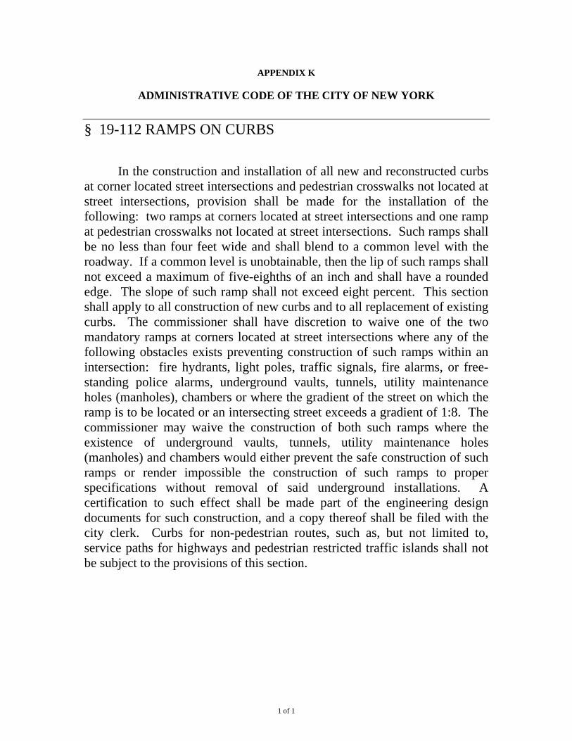
APPENDIX K
ADMINISTRATIVE CODE OF THE CITY OF NEW YORK § 19-112 RAMPS ON CURBS In the construction and installation of all new and reconstructed curbs at corner located street intersections and pedestrian crosswalks not located at street intersections, provision shall be made for the installation of the following: two ramps at corners located at street intersections and one ramp at pedestrian crosswalks not located at street intersections. Such ramps shall be no less than four feet wide and shall blend to a common level with the roadway. If a common level is unobtainable, then the lip of such ramps shall not exceed a maximum of five-eighths of an inch and shall have a rounded edge. The slope of such ramp shall not exceed eight percent. This section shall apply to all construction of new curbs and to all replacement of existing curbs. The commissioner shall have discretion to waive one of the two mandatory ramps at corners located at street intersections where any of the following obstacles exists preventing construction of such ramps within an intersection: fire hydrants, light poles, traffic signals, fire alarms, or free-standing police alarms, underground vaults, tunnels, utility maintenance holes (manholes), chambers or where the gradient of the street on which the ramp is to be located or an intersecting street exceeds a gradient of 1:8. The commissioner may waive the construction of both such ramps where the existence of underground vaults, tunnels, utility maintenance holes (manholes) and chambers would either prevent the safe construction of such ramps or render impossible the construction of such ramps to proper specifications without removal of said underground installations. A certification to such effect shall be made part of the engineering design documents for such construction, and a copy thereof shall be filed with the city clerk. Curbs for non-pedestrian routes, such as, but not limited to, service paths for highways and pedestrian restricted traffic islands shall not be subject to the provisions of this section.
1 of 1

APPENDIX L
DOT DESIGN DIRECTIVE #30 OF 1978 STANDARDIZATION OF PAVEMENT CROWN AND CROSS SECTION
Recommended Conclusions
1. Use a standard 7″ curb height with the above modification.
2. Obtain roadway crown and x-section from the following formula:
a) c = Δ + (w – a) (24 –%) 750
b) a = w2 24 – % 750
2w 24 – % 750
c) y′ = c x′ 1.5 d) y″ = (c – Δ) x″ 1.5
a (w – a)
– Δ
“c” is the total crown in feet. “Δ” is the difference in elevation between the two curb lines in feet. “w” is the width of roadway in feet. “a” is the distance from the lower curb line to the crown line in feet (at Δ = 0, a = w/2; at a ≥ w use a = w). “%” is the percent grade of the street in the longitudinal direction as a pure number. (Example – a 3′ fall in 100 feet is a 3% grade use 3 for % in the formula; above the limit of 8% (8) use 16 in the formula.) “y” is the vertical crown offset along any point x from the crown point (in feet). “x” is the horizontal distance from the crown point to any point along the curve (in feet).
1 of 3

2 of 3

3 of 3