instrumentation 02 - lecture symbology - lily … 2 themes •define p&id •identify various...
TRANSCRIPT

2/7/2016
1
Instrumentation TechnologyINST‐1010
SymbologyProcess and Instrumentation Diagrams ‐ P&IP
Basile Panoutsopoulos, Ph.D.
CCRI
Department of Engineering and Technology
1B. Panoutsopoulos Engineering Physics II
Today’s meeting
• Call Attendance• Announcements
• Collect Homework• Give examination
– Display time clock
• Collect examinations
• Previous examination– Return– Discussion
• Introduce topic– Provide Handouts– Socratic discussion– Practice ‐ Problems
B. Panoutsopoulos Engineering Physics II 2
Today’s meeting
• Call Attendance• Announcements
• Collect Homework• Give examination
– Display time clock
• Collect examinations
• Previous examination– Return– Discussion
• Introduce topic– Provide Handouts– Socratic discussion– Practice – Problems
• Reminder: Obey the rules
B. Panoutsopoulos Engineering Physics II 3
2/7/2016
2
Themes
• Define P&ID
• Identify various instruments by the shapes of balloons that represent them
• Identify and interpret functional identifiers in balloon symbols
• Describe how tag numbers pertain to an instrumentation loop
• Describe the function of line symbols
Instrumentation: Process Control 4
Themes
• Identify the symbols for various actuators and valves
• Read a simple loop on a P&ID
• Describe the various types of information on a title block
Instrumentation: Process Control 5
Themes
• Process Control
• Variables
• Automation
• Control Elements
• Control Loops
• Common Control Strategies
• Instrumentation
• Instrumentation and Industry
• Training
• Industry and Standards Organizations
Instrumentation: Process Control 6

2/7/2016
3
HISTORICAL INTRODUCTION
Instrumentation: Process Control 7
SIGNALS
Instrumentation: Process Control 8
• Discuss Signals
Instrumentation: Process Control 9

2/7/2016
4
GENERAL INSTRUMENT SYMBOLS
Instrumentation: Process Control 10
Symbols in Control EngineeringSignal flow diagrams
• A signal flow diagram is the symbolic representation of the functional interactions in a system.
• The essential components of control systems are represented by means of block diagrams.
• If required, the task represented by a block symbol can be further described by adding a written text.
• However, block diagrams are not suitable for very detailed representations.
• The symbols described below are better suited to represent functional details clearly.
Instrumentation: Process Control 11
Symbols in Control EngineeringBlocks and lines of action
• The functional relationship between an output signal and an input signal is symbolized by a rectangle (block).
• Input and output signals are represented by lines and their direction of action (input or output) is indicated by arrows.
Instrumentation: Process Control 12
2/7/2016
5
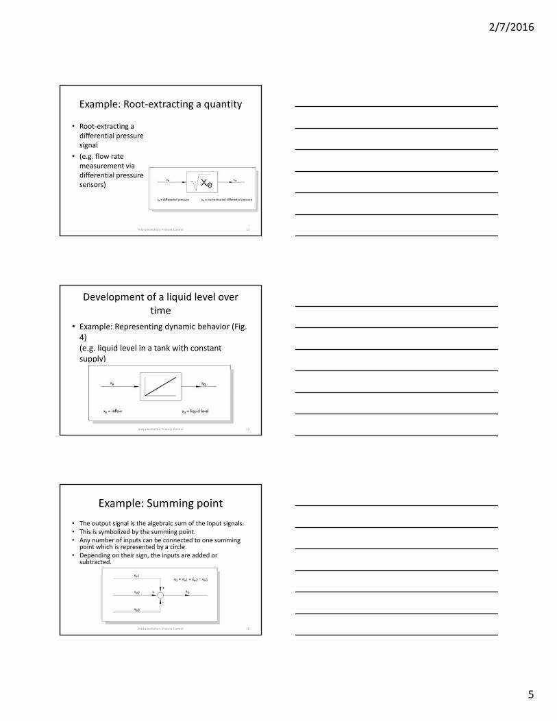
Example: Root‐extracting a quantity
• Root‐extracting a differential pressure signal
• (e.g. flow rate measurement via differential pressure sensors)
Instrumentation: Process Control 13
Development of a liquid level over time
• Example: Representing dynamic behavior (Fig. 4)(e.g. liquid level in a tank with constant supply)
Instrumentation: Process Control 14
Example: Summing point
• The output signal is the algebraic sum of the input signals. • This is symbolized by the summing point. • Any number of inputs can be connected to one summing
point which is represented by a circle. • Depending on their sign, the inputs are added or
subtracted.
Instrumentation: Process Control 15
2/7/2016
6
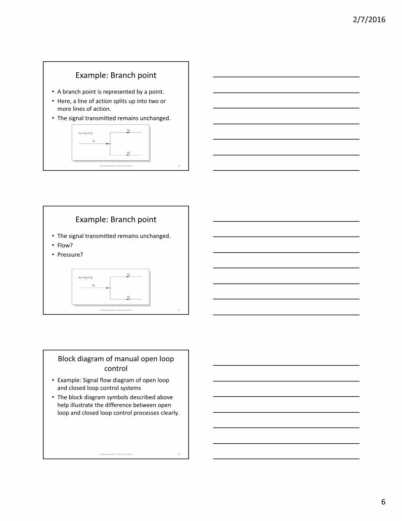
Example: Branch point
• A branch point is represented by a point.
• Here, a line of action splits up into two or more lines of action.
• The signal transmitted remains unchanged.
Instrumentation: Process Control 16
Example: Branch point
• The signal transmitted remains unchanged.
• Flow?
• Pressure?
Instrumentation: Process Control 17
Block diagram of manual open loop control
• Example: Signal flow diagram of open loop and closed loop control systems
• The block diagram symbols described above help illustrate the difference between open loop and closed loop control processes clearly.
Instrumentation: Process Control 18
2/7/2016
7
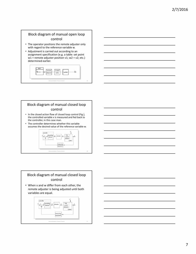
Block diagram of manual open loop control
• The operator positions the remote adjuster only with regard to the reference variable w.
• Adjustment is carried out according to an assignment specification (e.g. a table: set point w1 = remote adjuster position v1; w2 = v2; etc.) determined earlier.
Instrumentation: Process Control 19
Block diagram of manual closed loop control
• In the closed action flow of closed loop control (Fig.), the controlled variable x is measured and fed back to the controller, in this case man.
• The controller determines whether this variable assumes the desired value of the reference variable w.
Instrumentation: Process Control 20
Block diagram of manual closed loop control
• When x and w differ from each other, the remote adjuster is being adjusted until both variables are equal.
Instrumentation: Process Control 21

2/7/2016
8
Block diagram of a control loopDevice‐related representation
• Using the symbols and terminology defined above, Fig. shows the typical action diagram of a closed loop control system (abbreviations see page 10).
Instrumentation: Process Control 22
graphical symbolsfor detailed, solution related
representations• Whenever the technical solution of a process control
system shall be pointed out, it is recommended to use graphical symbols in the signal flow diagram (Fig. 10).
• As this representation method concentrates on the devices used to perform certain tasks in a process control system, it is referred to as solution‐related representation.
• Such graphical representations make up an essential part of the documentation when it comes to planning, assembling, testing, start‐up and maintenance.
Instrumentation: Process Control 23
Graphical symbols for describing temperature control
• Temperature control of a heat exchanger system– 1 Sensor (temperature) 2 Transmitter– 3 Signal converter 4 Controller– 5 Pneumatic linear valve 6 Heat exchanger
Instrumentation: Process Control 24

2/7/2016
9
Graphical symbols for describing temperature control
• Temperature control of a heat exchanger system– 1 Sensor (temp.) 2 Transmitter– 3 Signal converter 4 Controller– 5 Pneumatic linear valve 6 Heat exchanger
Instrumentation: Process Control 25
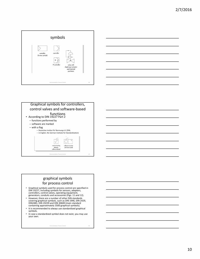
symbols
• Each unit has its own graphical symbol that is usually standardized.
• Equipment consisting of various units is often represented by several lined‐up symbols.
Instrumentation: Process Control 26
symbols
Instrumentation: Process Control 27
2/7/2016
10
symbols
Instrumentation: Process Control 28
Graphical symbols for controllers, control valves and software‐based
functions• According to DIN 19227 Part 2
– functions performed by
– software are marked
– with a flag– Deutsches Institut für Normung e.V. (DIN;
– in English, the German Institute for Standardization)
Instrumentation: Process Control 29
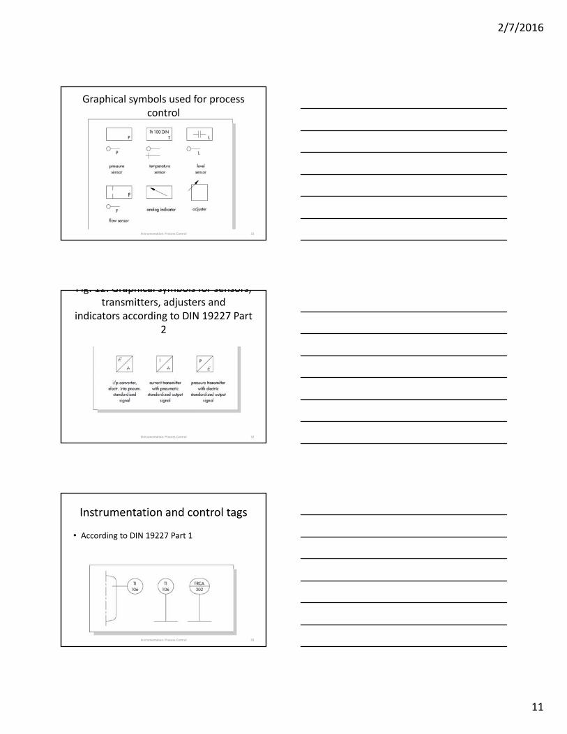
graphical symbolsfor process control
• Graphical symbols used for process control are specified in DIN 19227, including symbols for sensors, adapters, controllers, control valves, operating equipment, generators, conduits and accessories (Figs. 11 and 12).
• However, there are a number of other DIN standards covering graphical symbols, such as DIN 1946, DIN 2429, DIN2481, DIN 19239 and DIN 30600 (main standard containing approximately 3500 graphical symbols).
• It is recommended to always use standardized graphical symbols.
• In case a standardized symbol does not exist, you may use your own.
Instrumentation: Process Control 30
2/7/2016
11
Graphical symbols used for process control
Instrumentation: Process Control 31
Fig. 12: Graphical symbols for sensors, transmitters, adjusters and
indicators according to DIN 19227 Part 2
Instrumentation: Process Control 32
Instrumentation and control tags
• According to DIN 19227 Part 1
Instrumentation: Process Control 33
2/7/2016
12
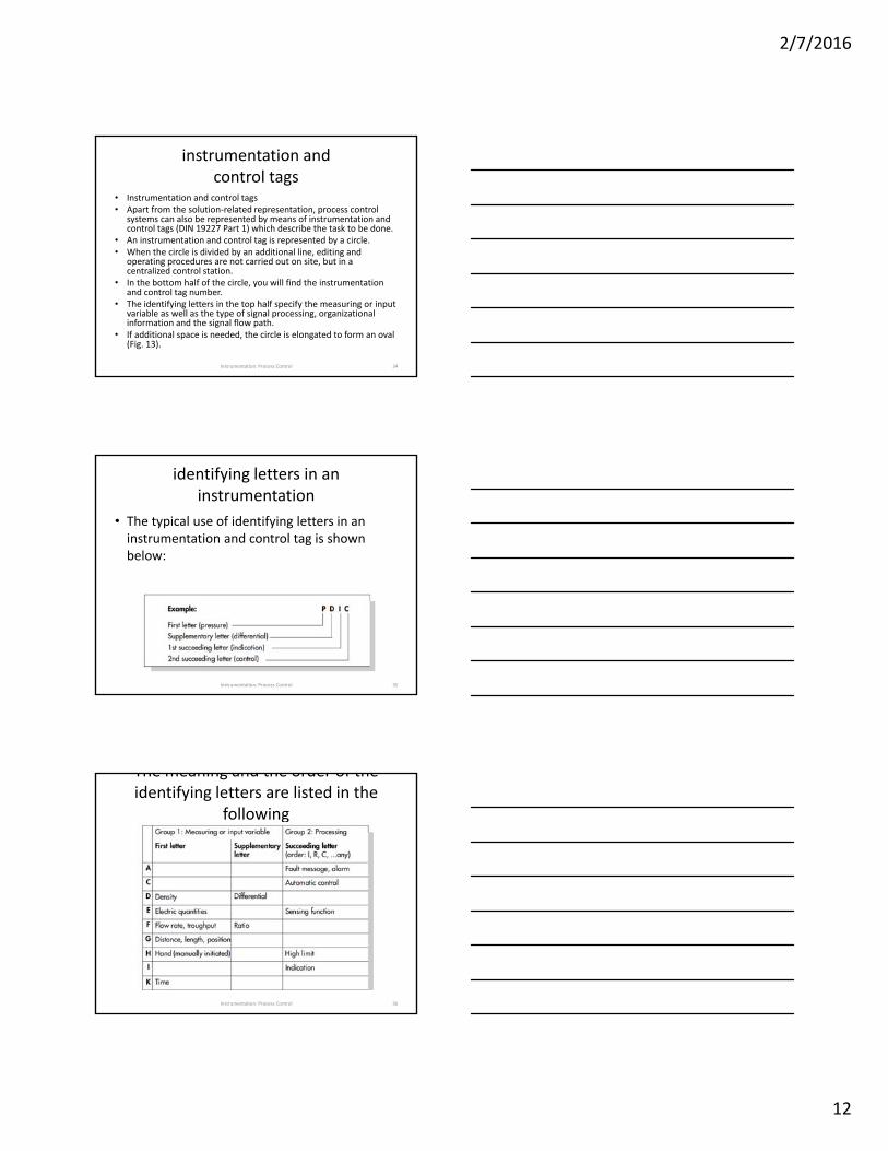
instrumentation andcontrol tags
• Instrumentation and control tags• Apart from the solution‐related representation, process control
systems can also be represented by means of instrumentation and control tags (DIN 19227 Part 1) which describe the task to be done.
• An instrumentation and control tag is represented by a circle. • When the circle is divided by an additional line, editing and
operating procedures are not carried out on site, but in a centralized control station.
• In the bottom half of the circle, you will find the instrumentation and control tag number.
• The identifying letters in the top half specify the measuring or input variable as well as the type of signal processing, organizational information and the signal flow path.
• If additional space is needed, the circle is elongated to form an oval (Fig. 13).
Instrumentation: Process Control 34
identifying letters in an instrumentation
• The typical use of identifying letters in an instrumentation and control tag is shown below:
Instrumentation: Process Control 35
The meaning and the order of the identifying letters are listed in the
followingtable.
Instrumentation: Process Control 36
2/7/2016
13
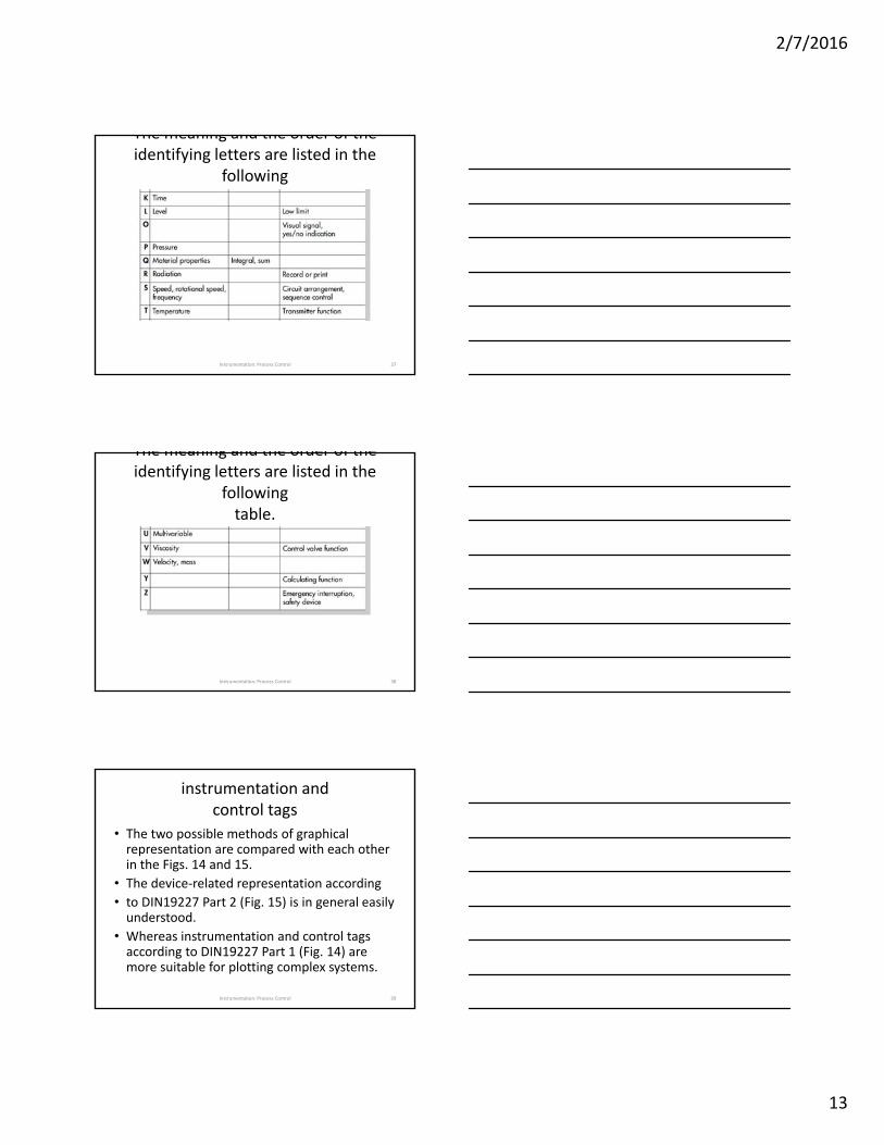
The meaning and the order of the identifying letters are listed in the
followingtable.
Instrumentation: Process Control 37
The meaning and the order of the identifying letters are listed in the
followingtable.
Instrumentation: Process Control 38
instrumentation andcontrol tags
• The two possible methods of graphical representation are compared with each other in the Figs. 14 and 15.
• The device‐related representation according
• to DIN19227 Part 2 (Fig. 15) is in general easily understood.
• Whereas instrumentation and control tags according to DIN19227 Part 1 (Fig. 14) are more suitable for plotting complex systems.
Instrumentation: Process Control 39

2/7/2016
14
Instrumentation and control tags
• Fig. 14: Representation of a control loop according to DIN 19227 Part 1
Instrumentation: Process Control 40
Representation of a control loop
• According to DIN 19227 Part 2device‐related symbols
Instrumentation: Process Control 41
General instrument or functional symbols
Instrumentation: Process Control 42

2/7/2016
15
General instrument or functional symbols
• Individual instruments
• Represented with a balloon
• Circle by itself
• Stand‐alone instrument
• Circle in a square
• Shared device
Instrumentation: Process Control 43
Tag Numbers
• Alphanumeric code • Placed inside each symbol to identify it• Functional identifiers• First letter: • P, T, F, and L• Second letter: • R, C, and T• Third and fourth letters• Example: PDAH
Instrumentation: Process Control 44
Tag Numbers
• List of standard identifiers
• See Table 16‐1 in the text
• Loop identifiers
• Located in bottom portion of the symbol
• Loop
• One or more instruments arranged to measure and control a process variable
Instrumentation: Process Control 45
2/7/2016
16
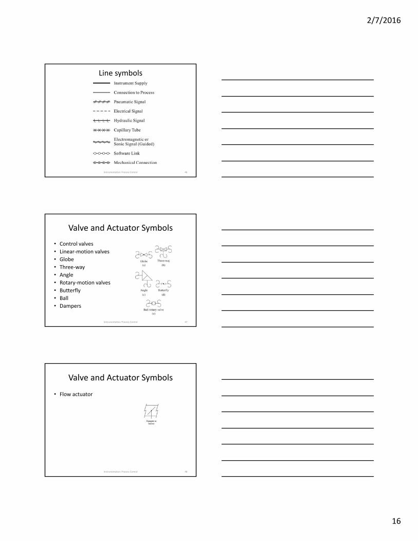
Line symbols
Instrumentation: Process Control 46
Valve and Actuator Symbols
• Control valves
• Linear‐motion valves
• Globe
• Three‐way
• Angle
• Rotary‐motion valves
• Butterfly
• Ball
• Dampers
Instrumentation: Process Control 47
Valve and Actuator Symbols
• Flow actuator
Instrumentation: Process Control 48
2/7/2016
17
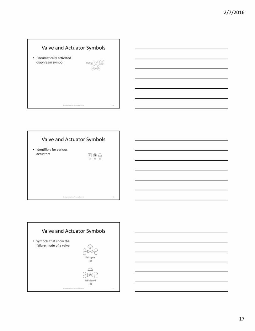
Valve and Actuator Symbols
• Pneumatically activated diaphragm symbol
Instrumentation: Process Control 49
Valve and Actuator Symbols
• Identifiers for various actuators
Instrumentation: Process Control 50
Valve and Actuator Symbols
• Symbols that show the failure mode of a valve
Instrumentation: Process Control 51
2/7/2016
18
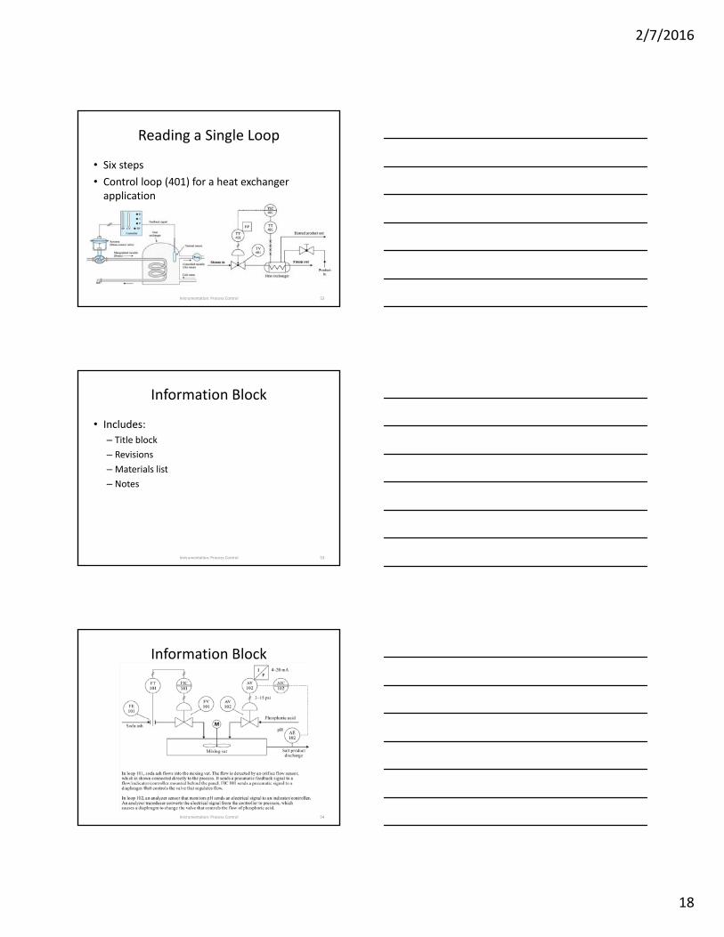
Reading a Single Loop
• Six steps
• Control loop (401) for a heat exchanger application
Instrumentation: Process Control 52
Information Block
• Includes:
– Title block
– Revisions
–Materials list
– Notes
Instrumentation: Process Control 53
Information Block
Instrumentation: Process Control 54

2/7/2016
19
The title block
Instrumentation: Process Control 55
Revisions
Instrumentation: Process Control 56
Material list
Instrumentation: Process Control 57

2/7/2016
20
SYNOPSIS
Instrumentation: Process Control 58
•The ISA has developed standard symbols and nomenclature used in instrumentation diagrams.
•Piping and instrumentation diagrams contain information about the instruments being used as well as the equipment employed.
2/7/2016
21
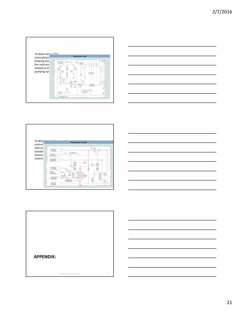
•A detail view of the recirculation tank drawing shows how the instruments are related to the pumping system.
•A detail view of the controls shows how information is transferred from instruments to final control elements.
APPENDIX:
Instrumentation: Process Control 63

2/7/2016
22
Explanation of hysteresis calculation
• a
Instrumentation: Process Control 64