instrumentation & control of nuclear power plants & control of nuclear power plants n. thuy...
TRANSCRIPT

Instrumentation & Control of Nuclear Power Plants
N. ThuyEdF R&D
CSD&M
November 12th-14th, 2014
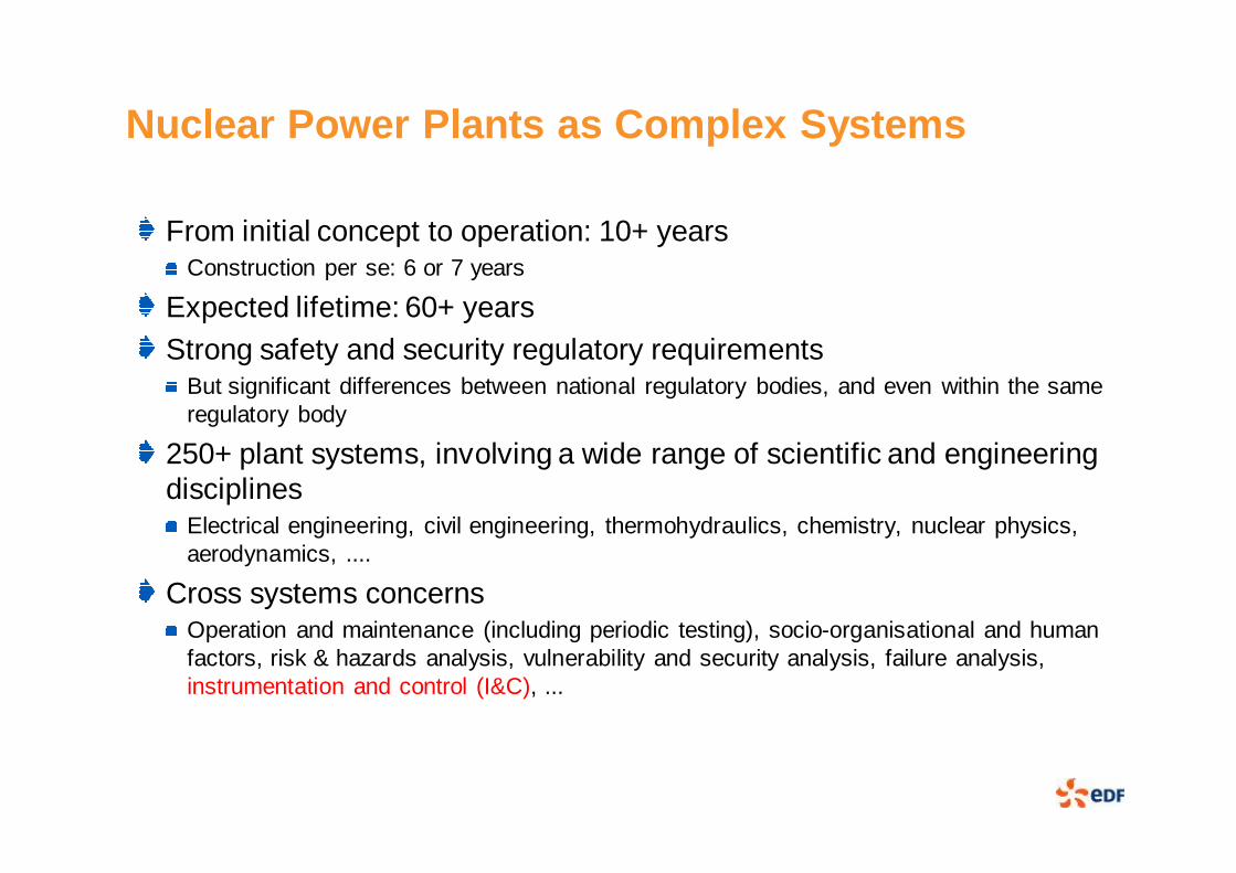
Nuclear Power Plants as Complex Systems
From initial concept to operation: 10+ yearsConstruction per se: 6 or 7 years
Expected lifetime: 60+ yearsStrong safety and security regulatory requirements
But significant differences between national regulatory bodies, and even within the same regulatory body
250+ plant systems, involving a wide range of scientific and engineering disciplines
Electrical engineering, civil engineering, thermohydraulics, chemistry, nuclear physics, aerodynamics, ....
Cross systems concernsOperation and maintenance (including periodic testing), socio-organisational and human factors, risk & hazards analysis, vulnerability and security analysis, failure analysis, instrumentation and control (I&C), ...
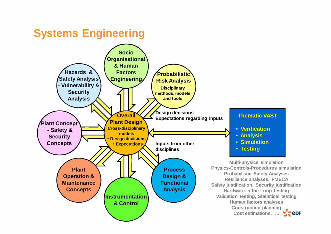
Systems Engineering
Overall Plant Design
Hazards & Safety Analysis- Vulnerability &
Security Analysis
Socio Organisational
& Human Factors
EngineeringProbabilistic Risk Analysis
Plant Operation & Maintenance
Concepts
Process Design &
Functional Analysis
Plant Concept- Safety & Security
Concepts
Instrumentation & Control
Design decisionsExpectations regarding inputs
Inputs from other disciplines
Thematic VAST
• Verification• Analysis• Simulation• Testing
Cross-disciplinary models
• Design decisions• Expectations
Disciplinary methods, models
and tools
Multi-physics simulationPhysics-Controls-Procedures simulation
Probabilistic Safety AnalysesResilience analyses, FMECA
Safety justification, Security justificationHardware-in-the-Loop testing
Validation testing, Statistical testingHuman factors analysesConstruction planningCost estimations, ...
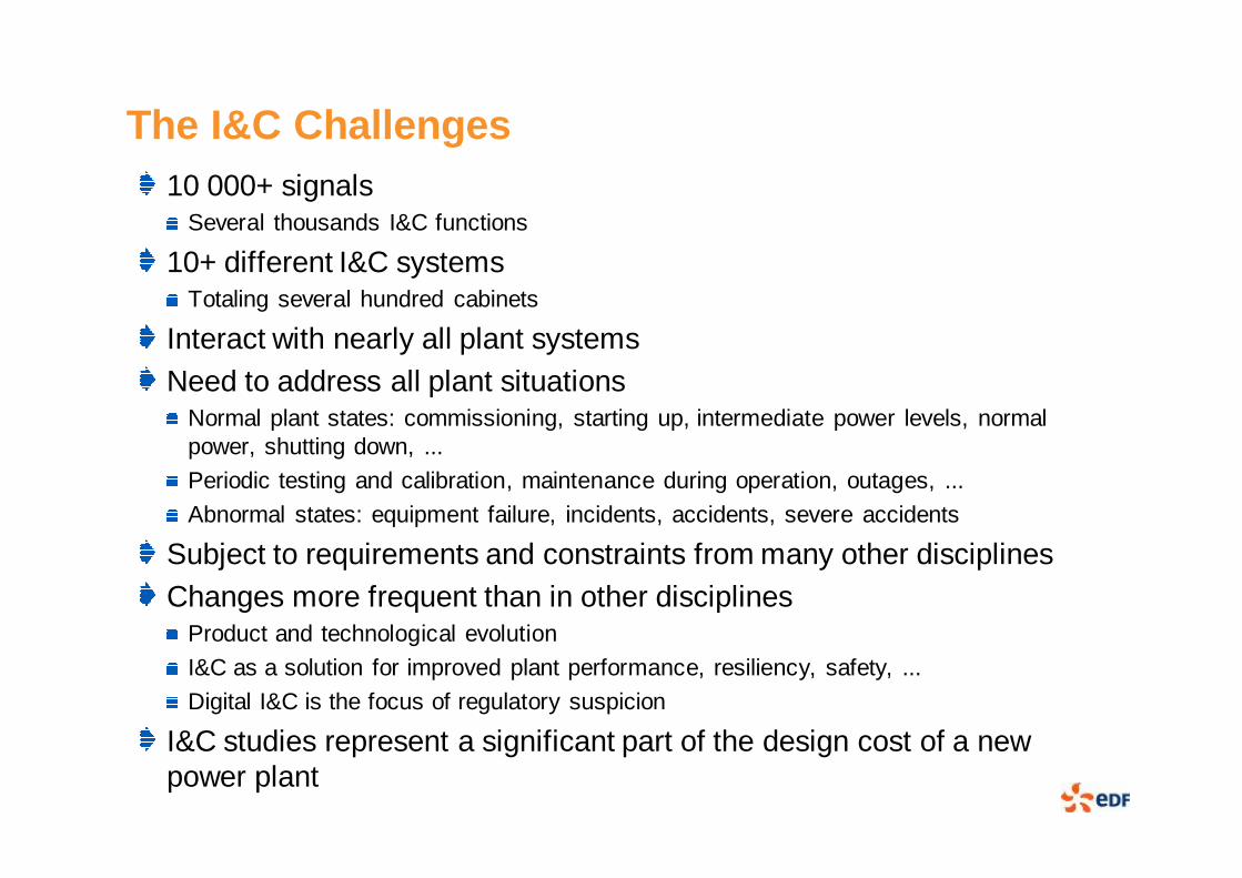
The I&C Challenges10 000+ signals
Several thousands I&C functions
10+ different I&C systemsTotaling several hundred cabinets
Interact with nearly all plant systemsNeed to address all plant situations
Normal plant states: commissioning, starting up, intermediate power levels, normal power, shutting down, ...
Periodic testing and calibration, maintenance during operation, outages, ...
Abnormal states: equipment failure, incidents, accidents, severe accidents
Subject to requirements and constraints from many other disciplinesChanges more frequent than in other disciplines
Product and technological evolution
I&C as a solution for improved plant performance, resiliency, safety, ...
Digital I&C is the focus of regulatory suspicion
I&C studies represent a significant part of the design cost of a new power plant

Examples of I&C Engineering Topics
Overall I&C architectural designOrganisation of the 10+ I&C systems into a safe, secure, functional, resilient whole
Levels of defence-in-depth / security zones, safety classification / security degrees, diversity, data communications, human-system interfaces, ...
Minimising, as far as reasonably feasible, the need for country specific features
Individual I&C systems architectural designSeveral thoudand functions, 100+ cabinets
Optimisation: minimise the number of necessary cabinetsSatisfy performance requirements, taking into account the processing required, inputs/outputs, and the characteristics of the platform chosen
Segmentation to reduce potential for complete system failure
Logical design verificationIncluding system architecture, software, FPGA logic, executable binary code
Testing, formal verification, proven compilers and generation tools, ...
Design of Human-System interfacesProbabilistic safety modelling and analysisVerification of I&C functional and timing requirements

By regulation, to prevent spurious deployment while
airborne, hydraulic circuits of thrust
reversers are disabled
Wheels on the ground ���� Thrust
reversers in operation
Pilots see a snow plough on the tarmac ���� They disengage the thrust reversers and
take-off
Wheels no longer on the ground ����
Hydraulic circuits disabled.
Reverser on one side is fully folded, but not
on the other side
Aerodynamic pressure reopens the thrust
reverser ���� Airplane is thrown off balance, pilots do not have
time to react
Small airport, No local control tower, Snowing, Poor visibility
Why is That Necessary?Experience from multiple industrial sectors shows that functional requirements are sometimes inadequate
Even for highly dependable systems
Errors will be revealed late in the development process, or worse, during operation
Such weaknesses result from multiple causesE.g., functional complexity or inadequate understanding or analysis of I&C system environment and operational context
Evolutionary designs limit the riskBut radically new designs need to address the issue more explicitly
One objective of the FP7 HARMONICS, ITEA2 MODRIO and CONNEXION projects is to enhance confidence in I&C functional and timing requirements

Overall Approach
Consider the functional and timing requirements for I&C in the framework of those of the parent plant system, and of the assumptions that system makes on its own environment
Including human actions, generally following specified operational procedures
Formal requirements and behavioural modelling(Massive) use of co-simulation to verify that requirements are satisfied
Physical processes, Human actions (and operational procedures), Automatic control
Also forSTPA (System Theoratical Process Analysis)
FMECA (Failure Modes, Effects and Consequences Analysis)
System validation (hardware-in-the-loop)
...

Step 1 - Non-Formal Plant System Analysis
A plant system needs, and assumes, certain behaviour from other plant systems or from operatorsOnce agreed, these assumptions become requirements for the other plant systems or for the operatorsA plant system is designed based on the requirements placed on it, but also on the assumptions it makes
Identification & characterisation of a plant system environment
All entities that interact with it (e.g., other plant systems, human operators)
Identification & characterisation of operational modes
Situations with specific behaviour and expectations
Including failure and abnormal situations
Assumptions and requirements may depend on operational modes
Assumption
Contract
Client Plant
System
Plant System
under study
Plant Operator
Requirement
Contract
Assumption
Requirement
Assumption
Contract
Supplier Plant
System
Requirement

Step 2 - Plant System Requirements Modelling
Formal modelling of the plant system and its environmentObject(s) representing the plant system
Objects interacting with the plant system and representing its environment
Operational modes
Assumptions on the plant system environment
Requirements regarding the plant system
At this stage, this is preferably not an imperative, deterministic modelTo avoid over-specification and the precluding of possible solutions
Formal modelling often helps improve the informal requirements specificationTool assisted verification may be used to detect overly constrained models (no possible solution), inconsistencies, incompleteness, ...
Deterministic behavioural model Non-deterministic requirements model

Step 3 - Plant System Overall Design Modelling
Identification and characterisation of the plant system main componentsIncluding Instrumentation & Control
Identification and characterisation of the plant system main internal modesAssumptions made on each component
Requirements, from the component standpoint
Allocation of plant system requirements
First in a non-formal manner, and then in a formal modelHere again, preferably not an imperative, deterministic model
Multiple design alternatives may be modelled and analysed
Plant System under study
Equipment
Equipment
I&C System
I&C Functions
Equipment

Step 4 - Plant System Overall Design Verification
Co-simulation of the requirements model and the overall design modelStimulation using a random generator of conformant scenarios
Such as StimuLus (from ArgoSim)
Conformant to assumptions made regarding the plant system environment and plant system components
Verification that the overall design satisfies the plant system requirements
The I&C functional and timing requirements specification are part of the plant system overall design
Application of coverage criteria
Assumptions on Plant System Environment
Plant System Requirements
Plant System Overall Design
Assumptions on Plant System
Components
Random Generator of Conformant Behaviours
Simulation Results Analyser
Simulation HSI
Specification of Simulation Objectives &
Scenarios
Step 5 - Detailed Design and Verification
As design becomes more detailed, the precise behaviour of individual components can be represented by deterministic, behavioural models
E.g., in MODELICA for the physical process
In functional diagrams for I&C functions
Detailed design decisions just need to comply with the overall design

Modelling
Process modelsModels based on ad hoc techniques
Models based on general, multi-physics modelling languages, e.g., MODELICA
Multiple models can cooperate using the FMI (Functional Mock-up Interface)
MODELICA is being extended by the ITEA2 project MODRIOFOrmal Requirements Modelling Language (FORM-L), to formally specify requirements and assumptions at process level
Stochastic modelling, to model random events such as components failures
Multi-mode modelling, to facilitate the representation of components failure modes

FORM-L
The language allows the expression of Requirements to be satisfied
Functional & timing requirements
Fault-tolerance and probabilistic requirements
Assumptions made on the environment of the system
Overall design decisionsSuch as allocation of requirements to system components
Designed to be undertandable by application domain expertsWho are not necessarily modelling experts
Graphic version of the language allowing different graphic styles and natural languages (dialects)

FORM-L Main Concepts
FORM-L addresses four main questions: WHAT, WHEN, WHERE and HOW WELLWHAT
Boolean conditions
Duration of Boolean conditions
Constraints on the number of occurrences of an event
WHEN (temporal logic)During time periods (with duration)
At particular instants (without duration)
During "sliding time windows"
WHERESets of objects concerned
Set memberships often not know at requirements specification
HOW WELLFault tolerance
(Conditional) failure probabilities
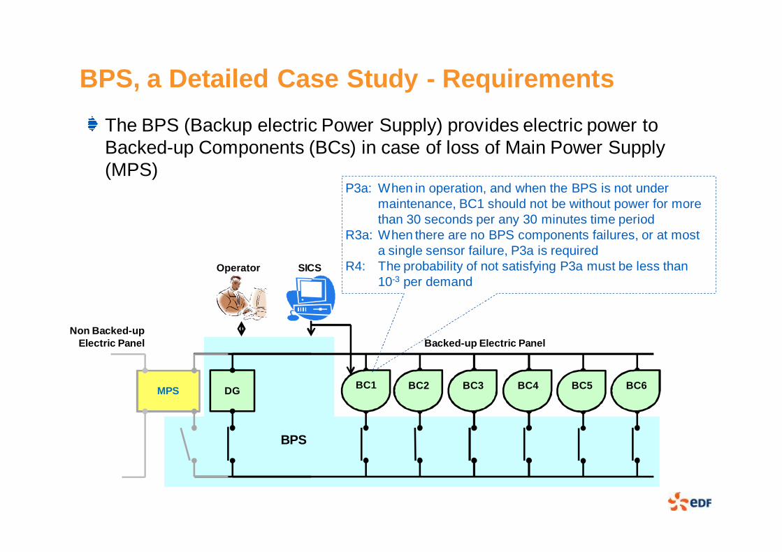
BPS, a Detailed Case Study - Requirements
The BPS (Backup electric Power Supply) provides electric power to Backed-up Components (BCs) in case of loss of Main Power Supply (MPS)
BC1 BC2 BC3 BC4 BC6BC5MPS DG
Backed-up Electric PanelNon Backed-up
Electric Panel
BPS
Operator SICS
P3a: When in operation, and when the BPS is not under maintenance, BC1 should not be without power for more than 30 seconds per any 30 minutes time period
R3a: When there are no BPS components failures, or at most a single sensor failure, P3a is required
R4: The probability of not satisfying P3a must be less than 10-3 per demand

BPS Overall Design
The DGLS (Diesel Generator Load Sequencer) is the control system of the BPS
It operates in a discrete time domain
The BPS overall design specifies requirements for the DGLS
BC 6
Non Backed-up Electric Panel
MPS DG
BVBVNBV
Step1DGFDGV
Backed-up Electric Panel
Step2 Step3 Step4 Step5 Step6 Step7 Step8 Step9
BC 1
Operator SICSDGLS
BC 2 - 5
BPS

I&C Requirements Specification in FORM-LDGLS-R9: When reloading is allowed, the required, unpowered Step with the highest priority shall be reloaded within 100 ms
When there are remaining required, unpowered Steps
An unrequired Step may become required at any momentBoolean reloadingAllowed;
class StepBoolean required;Integer priority;Breaker brk;end Step;
class Breakerevent openOrder;event closeOrder; fsa state = {open, closing, closed, opening} ... end state;...end Breaker;
Step step[9] .... // initialiationend step;
Step stepsToBeReloaded = {s ∈ step | s.required and not s.brk.state=closed};
Integer maxPriority = max{stepsToBeReloaded.priority};
Step candidate = any{s ∈ stepsToBeReloaded | s.priority = maxPriority};
requirement R9 =when (reloadingAllowed and card(stepsToBeReloaded)>0) becomes truewithin ms100check candidate.brk.closeOrder;

BPS Formal Models
BPS.REQRequirements &
Environment(FORM-L)
BPS.ODSOverall Design
(FORM-L)
BPS.ENVEnvironment
(StimuLus)
stimulates
implements
stimulates
BPS.REQRequirements &
Environment(FORM-L)
BPS.ODSOverall Design
(FORM-L)
BPS.BEVDetailed Design
(Modelica + Functional Diagrams)
BPS.ENVEnvironment
(StimuLus)
implementsstimulates
implements
stimulates

Conclusion
More explicit statement of WHY I&C requirements are as they areParticularly useful when systems are revisited (for upgrades for example) many years after initial development
Helps identify possible impacts of plant systems modifications on I&CThe same models may be used for various purposes
Improve confidence in requirements
Early design functional verification
Probabilistic and failure analyses
FMECA
Hardware-in-the-Loop testing
...