instru(:tion manual - textfiles.com · instru(:tion manual tu55 ... theory of operation ... tu55...
TRANSCRIPT
INSTRU(:TION MANUAL
TU55 DECtape 55
DIGITAL EQUIPMENT CORPORATIC1N • MAYNARD. MASSACHUSETTS
TUBS DECtape 55
INSTRUCTICJN MANUAL
September 1968
DEC-OO-HZTA-D
DIGITAL EQUIPMENT CORPORATIOI\l • MAYNARD, MASSACHUSETTS
1st Printing November 1966 2nd Printing February 1967 3rd Printing June 1967 4th Printing October 1968 5th Printing November 1968 6th Pri nti ng May 1969
Copyright © 1969 by Digital Equipment Corporation
Instruction times, operating speeds and the like are included in this manual for reference only; they are not to be taken as specifications.
The following are registered trademarks of Digital Equipment Corporation, ~ynard, Massachusetts:
DEC FLIP CHIP DIGITAL
ii
PDP FOCAL COMPUTER LAB

CONTENTS
Page
CHAPTER 1 INTRODUCTION AND DESCRIPTION
1.1 Genera I Descri pti on 1-·1
1.2 Scope of Manual 1-2
1.3 Pertinent Documents 1-2
1.3. 1 Manuals 1-2
1.3.2 Engineering Drawings 1-2
1.3.3 New Module News Bulletins 1-3
1.4 Functional Description 1-3
1.5 Physical Description 1-4
1.5. 1 Electrica I Detai Is 1-6
1.6 TU55 Performance Characteri sti cs 1-9
CHAPTER 2 THEORY OF OPERATION
2. 1 Block Diagram Analysis 2-1
2.2 Detai led Descripti ons 2-4
2.2. 1 Interface 2-4
2.2.2 Unit Select Lines 2-5
2.2.3 Command Lines 2-5
2.2.4 WRITE ENABLE Signal 2-5
2.2.5 Interface Connections 2-6
2.2.6 Read,IvVrite Head 2-6
2.2.7 Tape Moti on Contro I 2-6
2.2.8 Remote or Programmed Controi 2-6
2.2.9 Local {Manual} Control 2-7
2.2. 10 Motor Control 2-7
2.2. 11 Transport Selected Signal 2-8
2.3 Module Descriptions 2-9
2.3. 1 Type R303 Integrating One Shot {Delay} 2-9
2.3.2 Type W513 Level Amplifier 2-10
2.3.3 Type G850 SCR Motor Driver 2-11

CONTENTS (Cont)
Page
CHAPTER 3 OPERATION
3. 1 Introduction 3-1
3.2 Controls and Indicators 3-1
3.2. 1 Operating Notes 3-1
3.3 Loading Tape 3-1
CHAPTER 4 MAINTENANCE
4-. 1 Equipment Required 4-1
4-.2 Preventive Maintenance 4-1
4.2. 1 Weekly Schedule 4-1
4.2.2 Monthly Schedule 4-2
4.3 Tape Tens i on and Transport Stop Ad i ustment 4-2
4.4 Head Output Check 4-3
4.5 Head-Skew Check 4-4
4-.6 Write Enable Circuit Check 4-5
4.7 Troubleshooting 4-6
4·.8 Recommended Spare 4-7
CHAPTER 5 ENGINEERING DRAWINGS
5. 1 Introducti on 5-1
5.2 Ci rcuit Symbols 5-1
5.3 Logic Signal Symbols 5-1
5.3. 1 Logic Levels 5-1
5.3.2 FLIP CHIP Pulses 5-1
5.4 Sem i cond uctor Substi tuti on 5-4
ILLUSTRATIONS
1-1 Type TU55 DECtape Transport 1-1
1-2 Hub and Ree I Assembl y 1-5
1-3 Arrangement of DECtape Head 1-6
1-4 Type TU55 DECtape Transport, Rear View 1-7
iv

ILLUSTRATllONS (Cont)
Page
1-5 TU55 Interface Connections 1-8
2-1 DECtape Transport TU55 Block Dia!~ram 2-1
2-2 Head Connections 2-4
2-3 Schematic of R303 Integrating One-Shot 2-10
2-4 Schematic of G850 SCR Motor Drive 2-11
4-1 Module Adjustment Trimports 4-3
5-1 DEC Symbols 5-2
5-2 FLIP CHIP R-Series Pulse 5-4
5-3 FLIP CHIP B-Series Pulse 5-4
Module Schematics
Solid State DECtape Transport, TU55-0-2 5-5
Module Utilization List, TU55-0-5 5-7
Bus Bar for TU55, TU55-0-4 5-7
Relay, G851 5-8
Diode Cluster, ROO2 5-8
Inverter, R107 5-9
Diode Gate, R111 5-9
Dual FI ip-Flop, R202 5-10
Integrating One-Shot, R303 5-10
Solenoid Driver, W040 5-11
Level Amplifier, W513 5-11
TAB.LES
1-1 Summary of Equipment Characteristics for the TU55 DECtape Transport 1-9
2-1 Motor and Brake Operation Truth T'::1ble 2-9
3-1 Functions of Controls and Indicators 3-2
4-1 Recommended Maintenance Equipm,ent 4-1
4-2 Recommended Spare Parts 4-7
5-1 Sem i cond uctor Substi tuti on 5-4
v


CHAPTER 1
INTRODUCTION AND DESCRIPTION
1 .1 GENERAL DESCRIPTION
The Type TU55 DECtape Transport (see fiHure 1-1) is a solid-state, bidirectional, magnetic
tape handl il1~~ device designed and manufactured by the Digital Equipment Corporation (DEC) for use in
. DEC digital computer systems. When used with a su itable DECtape control system, the TU55 provides a
fixed-address magnetic-tape facility for high-speed loading, readout, and program updating. The DEC
tape control system directs the transport to read forward or in reverse, to write forward or in reverse, to
stop, and to go. The TU55 contains tape handl ing elements, drive mechan isms, and sol id-state switching
circuits which switch the tape head onto a master bus system and interpret command instructions from the
control un it. The highly rei iable sol id-state switching circuits in the TU55 are completely compatible
with the Type 555 DECtape Transport (which uses rel,oy switching) cmd may be used to modify and
expand systems employing this type of transport.
Fi gure 1 -1 Type TU55 DECtape Transport
1-1
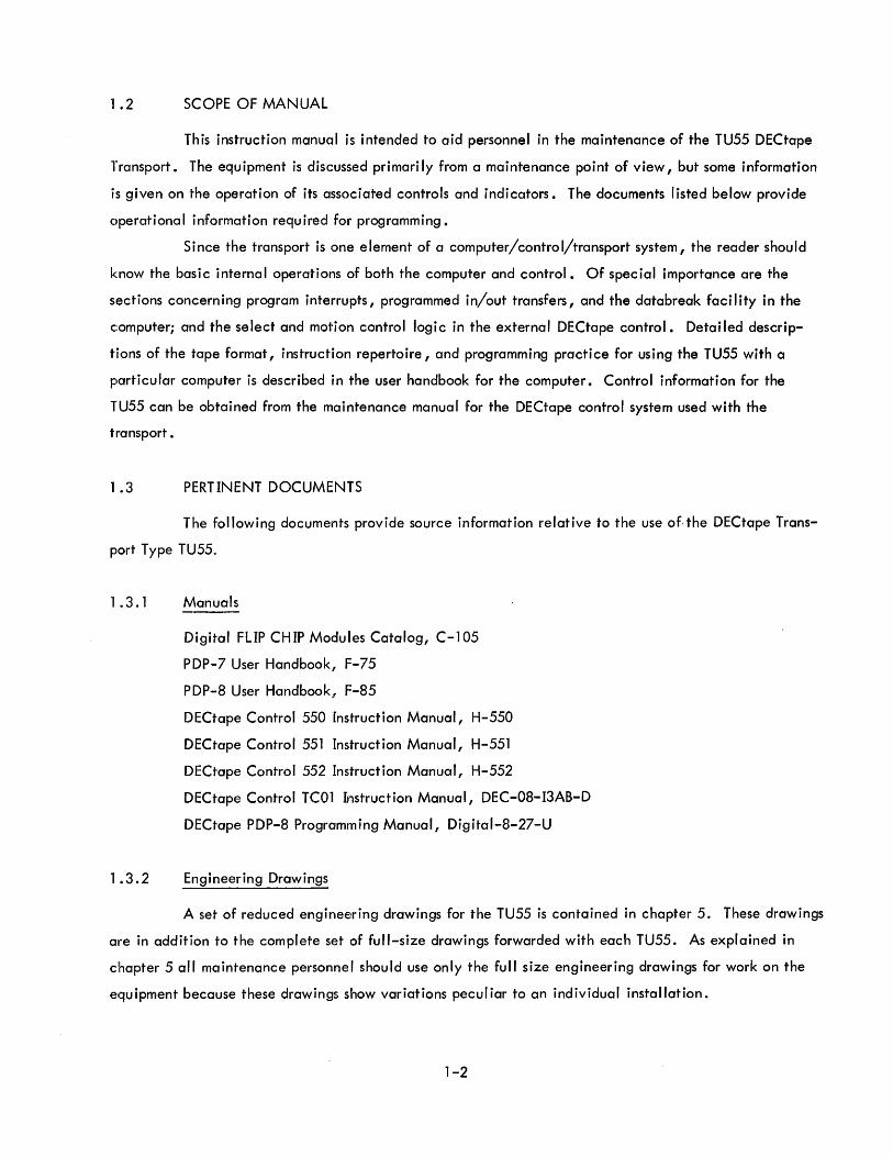
1 .2 SCOPE OF MANUAL
This instruction manual is intended to aid personnel in the maintenance of the TU55 DECtape
Transport. The equipment is discussed primari Iy from a maintenance point of view, but some information
is given on the operation of its associated controls and indicators. The documents listed below provide
operational information required for programming.
Since the transport is one element of a computer/control/transport system, the reader should
know the basic internal operations of both the computer and control. Of special importance are the
sections concern ing program interrupts, programmed in/out transfers, and the databreak faci I ity in the
c:omputer; and the select and motion control logic in the external DECtape control. Detailed descrip
tions of the tape format, instruction repertoire, and programming practice for using the TU55 with a
particular computer is described in the user handbook for the computer. Control information for the
TU55 can be obtained from the maintenance manual for the DECtape control system used with the
transport.
1 .3 PERTINENT DOCUMENTS
The following documents provide source information relative to the use of. the DECtape Trans
port Type TU55.
1 .3.1 Manuals
1 .3.2
Digital FLIP CHIP Modules Catalog, C-105
PDP-7 User Handbook, F-75
PDP-8 User Handbook, F-85
DECtape Control 550 Instruction Manual, H-550
DECtape Control 551 Instruction Manual, H-551
DECtape Control 552 Instruction Manual, H-552
DECtape Control TC01 Instruction Manual, DEC-08-I3AB-D
DECtape PDP-8 Programming Manual, Digital-8-27-U
Engineering Drawings
A set of reduced engineering drawings for the TU55 is contained in chapter 5. These drawings
are in addition to the complete set of full-size drawings forwarded with each TU55. As explained in
chapter 5 all maintenance personnel should use only the full size engineering drawings for work on the
equipment because these drawings show variations pecul iar to an individual installation.
1-2
1.3.3 New Module News Bulletins
G850 SCR Motor Driver
G851 Relay
W513 Level Ampl ifier
In addition to the above documents, complete sets of Library Programs are available for each
computer using DECtape systems.
1 .4 FUNCTIONAL DESCRIPTION
The TU55 Transport provides a read/write head for recording and playback of information on
five channels of the O.75-inch tape. Each channe!1 consists of two nonadjacent coils which are wired
in series. Thus, information on one track combines with redundant information on another to create a
single signal. Connections from the read/write head are made directly to the external control unit which
contains the read and write amplifiers as well as the command logic for the selection and remote control
of tape motion.
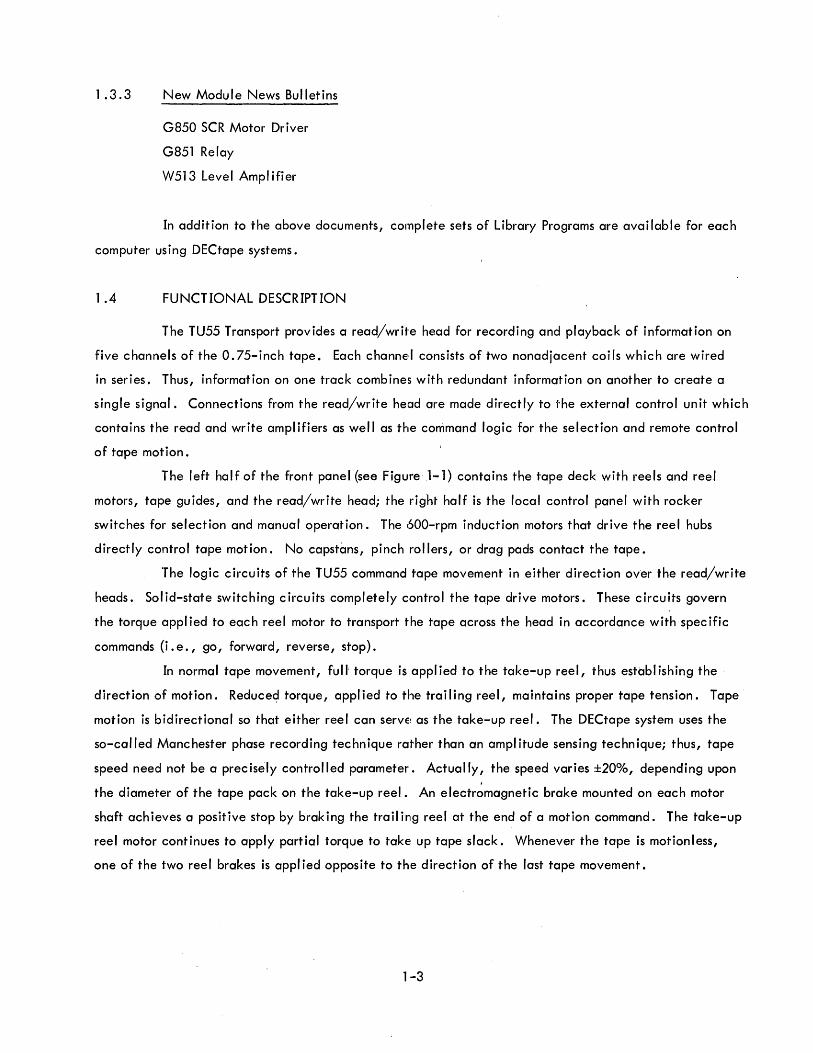
The left half of the front panel (see Figure 1-1) contains the tape deck with reels and reel
motors, tape guides, and the read/write head; the right half is the local control panel with rocker
switches foil" selection and manual operation. The bOO-rpm induction motors that drive the reel hubs
directly control tape motion. No capstans, pinch rollers, or drag pads contact the tape.
The logic circuits of the TU55 command tape movement in either direction over the read/write
heads. Solid-state switching circuits completely control the tape drive motors. These circuits govern
the torque appl ied to eac h reel motor to transport the tape across the head in accordance with spec ific
commands (i. e ., go, forward, reverse, stop).
[n normal tape movement, full' torque is appl ied to the take-up reel, thus establ ishing the
direction of motion. Reduce~torque, applied to the trailing reel, maintains proper tape tension. Tape
motion is bidirectional so that either reel can SerVE! as the take-up reel. The DECtape system uses the
so-called Manchester phase recording technique rather than an amplitude sensing technique; thus, tape
speed need not be a prec isely controlled parameter. Actually, the speed varies ±20%, depending upon
the diameter of the tape pack on the take-up reel. An electromagnetic brake mounted on each motor
shaft achieves a positive stop by braking the trailing reel at the end of a motion command. The take-up
reel motor continues to apply partial torque to take up tape slack. Whenever the tape is motionless,
one of the two reel brakes is appl ied opposite to the direction of the last tape movement.
1,-3

Tape movement is controlled either by commands originating in the computer and applied to
the TU55 via a suitable DECtape control system, or by commands generated through manual operation
of rocker type switches located on the front panel of the transport. Typical DECtape control systems
which allow transfer of information between the computer and the TU55 are as follows:
Computer
PDP-1, -4 and -7
PDP-6
PDP-5 and -8
PDP-8
PDP-9
Typical DECtape Control System
Type 550
Type 551
Type 552
TC01
TC02
Manual control is used to mount new reels of tape on the TU55 or as a quick maintenance check for
proper operation of the control logic in moving the tape.
External DECtape control systems may control up to eight individually addressed TU55s to
read or write tape. The operator may select the address of each drive by adjusting the thumbwheel
selector at the center of the TU55 local control panel (see figure 1-1). The operator may also place
the drive off-I ine by a setting on the same thumbwheel or by switching the drive for local operation.
In local operation, the head is disconnected and the rocker switches on the local control panel regu
late tape motion.
1.,5 PHYSICAL DESCRIPTION
All components of the TU55 are mounted on a preformed and assembled chassis. Roller slides
that allow easy access to the top, sides, and rear of t~e drive hold the chassis in a standard DEC bay.
D,::>uble doors in the front and rear are held closed by magnetIc latches. Power suppl ies and controls
are mounted on the rear of the DEC bay. Generally, the transport is mounted with others in the same
bClY that contains the DECtape control system.
The tape deck is machined from 3/8-inch cast aluminum plate and held to the chassis by cap
screws at the corners. Reel motors, tape guides and the head are secured only to the deck. This
arrangement preserves the integrity of the tape al ignment by the rigidity of the deck plate. Heavy
extruded aluminum plates at the top and bottom front of the chassis serve as bumpers to protect the
deck and control panel. The head is mounted in direct contact with the deck and is secured at both
sides by brackets. Head azimuth is set during manufacture of the drive and cannot be adjusted in the
field.
1-4
CAUTION
No attempt should be made to loosen 1rhe brackets and change the head position.
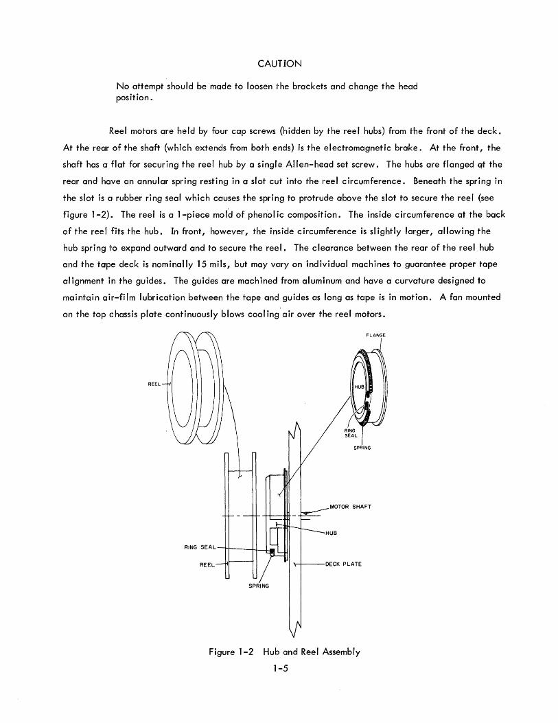
Reel motors are held by four cap screws {hidden by the reel hubs} from the front of the deck.
At the rear of the shaft {which extends from both ends} is the electromagnetic brake. At the front, the
shaft has a flat for securing the reel hub by a singl,e Allen-head set screw. The hubs are flanged Glt the
rear and have an annular spring resting in a slot cut into the reel circumference. Beneath the spring in
the slot is a rubber ring seal which causes the spring to protrude above the slot to secure the reel {see
figure 1-2}. The reel is a 1-piece mold of phenolic composition. The inside circumference at the back
of the reel fits the hub. In front, however, the inside circumference is slightly larger, allowing the
hub spring 1'0 expand outward and to secure the reel. The clearance between the rear of the reel hub
and the tape deck is nominally 15 mils, but may vClry on individual machines to guarantee proper tape
alignment in the guides. The guides are machined from aluminum and have a curvature designed to
maintain air-film lubrication between the tape and guides as long as tape is in motion. A fan mounted
on the top chassis plate continuously blows cool ing' air over the reel motors.
REEL
HUB
RING SE A L ---r"'t"---I-I---l...J
REEL '\-i---DECK PLATE
SPRING
Figure 1-2 Hub fJnd Reel Assembly
1-5
FLANGE
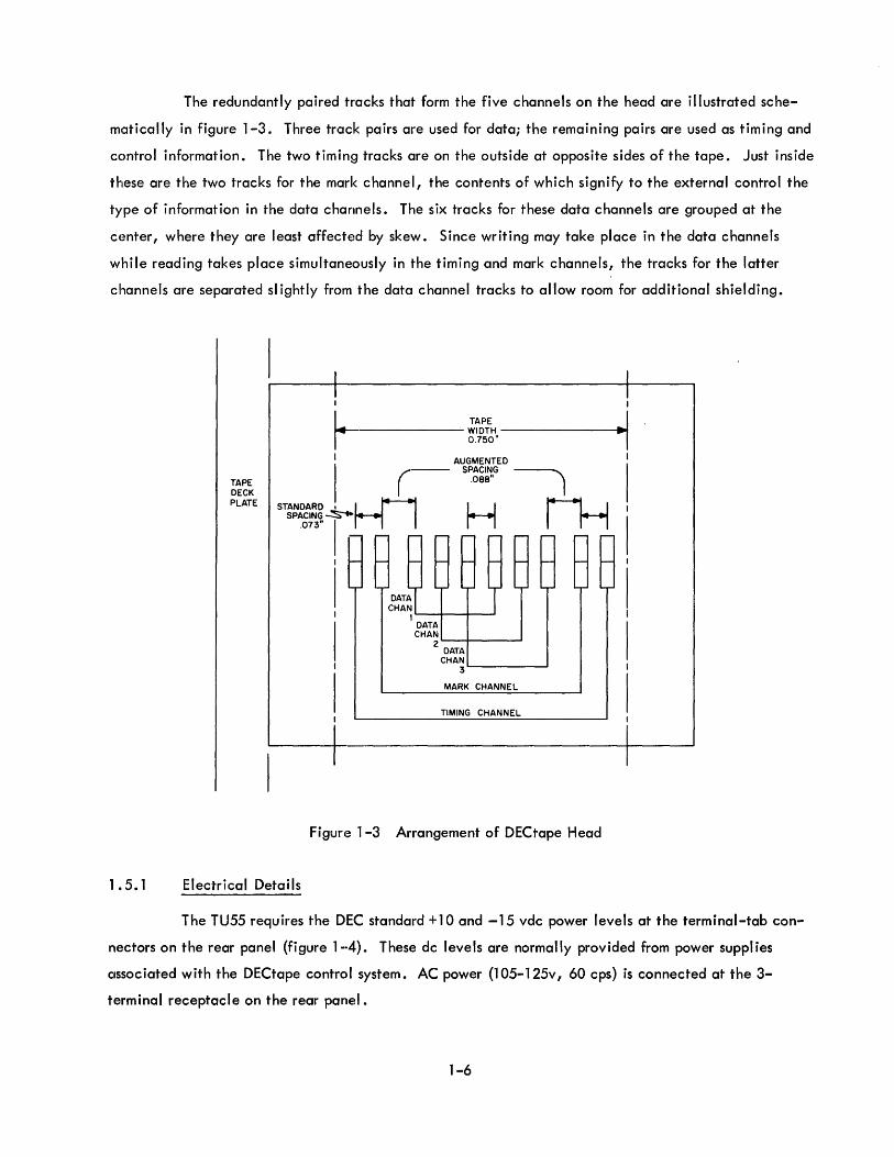
The redundantly paired tracks that form the five channels on the head are illustrated sche
matically in figure 1-3. Three track pairs are used for data; the remaining pairs are used as timing and
control information. The two timing tracks are on the outside at opposite sides of the tape. Just inside
these are the two tracks for the mark channel, the contents of which signify to the external control the
type of information in the data channels. The six tracks for these data channels are grouped at the
center, where they are least affected by skew. Since writing may take place in the data channels
while reading takes place simultaneously in the timing and mark channels, the tracks for the latter
channels are separated sl ightly from the data channel tracks to allow room for additional shielding.
1 .5. 1
TAPE DECK PLATE
I TAPE
II1II41-------- WIDTH ---------I .. ~ 0.750"
II (- A~~~~~~ED ~
.oee" I
STANDARD I H1 H rH SPACING~ .073" I
I
I I
I I
I
DATA CHAN
1 '----+---1_-' DATA CHAN
2L.....--+---....... DATA
CHAN 3L.....----.......
MARK CHANNEL
TIMING CHANNEL
Figure 1-3 Arrangement of DECtape Head
Electrical Details
The TU55 requires the DEC standard +10 and -15 vdc power levels at the terminal-tab con
nectors on the rear panel (figure 1-4). These dc levels are normally provided from power suppl ies
associated with the DECtape control system. AC power (1 05-125v, 60 cps) is connected at the 3-
terminal receptacle on the rear panel.
1-6
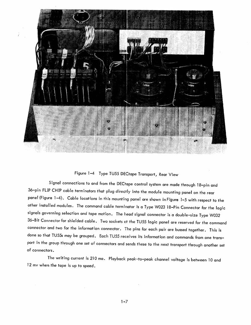
Figure 1-4 Type TU55 DECtape Transport, Rear View
Signal connections to and from the DECtape control system are made through 18-pin and
36-pin FLIP CHIP cable terminators that plug direc~ ly into the module mounting panel on the rear
panel (Figure 1-4). Cable locations in this mounting panel are shown in Figure 1-5 with respect to the
other insta f.f ed modules. The command cable terminator is a Type W023 18-Pin Connector for the logic
signals governing selection and tape motion. The head signal connector is a double-size Type W032
36-Bit Connector for shielded cable. Two sockets at the TU55 logic panel are reserved for the command
connector and two for the information connector. The pins for each pair are bussed together. This is
done so that TU55s may be grouped. Each TU55 receives its information and commands from one trans
port in the group through one set of connectors and sends these to the next transport through another set
of connectors.
The writing current is 210 ma. Playback peak-to-peak channel voltage is between 10 and
12 mv when the tape is up to speed.
1-7
r---------------------------------------------------,
..J <! ZIr Q o (fJ1-
U OW ZZ <!z ::!;o ::!;u o u
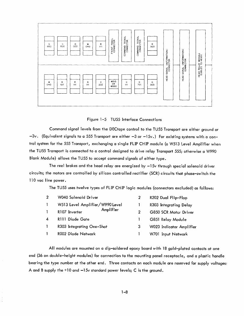
Figure 1-5 TU55 Interface Connections
z 0 f= <! ::!; Ir
f2 ~ ..J <! Z (!)
U; Cl <! W J:
w ..J ::> 0
cr 0
~ ::!;
u )0-w <! Z ..J Z w 0 Ir U
Cl <! W J:
Command signal levels from the DECtape control to the TU55 Transport are either ground or
-3v. {Equivalent signals to a 555 Transport are either -3 or -15v.} For existing systems with a con
trol system for the 555 Transport, exchanging a single FLIP CH IP module {a W513 Level Ampl ifier when
the TU55 Transport is connected to a control designed to drive relay Transport 555; otherwise a W990
B~ank Module} allows the TU55 to accept command signals of either type.
The reel brakes and the head relay are energized by -15v through special solenoid driver
circuits; the motors are controlled by sil icon controlled rectifier (SCR) c ircu its that phase-switch the
11 0 vac line power.
The TU55 uses twelve 'types of FLIP CHIP logic modules {connectors excluded} as follows:
2 W040 Solenoid Driver 2 R202 Dual FI ip-Flop
W513 Level Ampl ifier /W990 Level R303 Integrating Delay
1 R 107 Inverter Amplifier
2 G850 SCR Motor Driver
4 R111 Diode Gate G851 Relay Module
R303 Integrating One-Shot 3 W023 Indicator Amplifier
R002 Diode Network W701 Input Network
All modules are mounted on a dip-soldered epoxy board 'Nith 18 gold-plated contacts at one
end {36 on double-height modules} for connection to the mounting panel receptacle, and a plastic handle
bearing the type number at the other end. Three contacts on each module are reserved for supply voltages:
A and B supply the +10 and -15v standard power levels; C is the ground.
1-8

1 .6 TU55 PERFORMANCE CHARACTERISTICS
A summary of the characteristics of the TU55 equ ipment is given in table 1-1 •
TABLE 1-1 SUMMARY OF EQUIPMENT CHARACTERISTICS FOR THE TU55 DECTAPE TRANSPORT
Overall Size
Mounting
Power Requirements
Connectors
Cooling
Operat i ng Temperature
Humidity
General
10-1/2 in. high, 19-1/2 in. wide, 9-3/4 in. deep
Standard 19-in. rack. Four #10-32 screws mount chassis track assembly which holds transport.
Chassis can be extended 16-3/4 in. beyond mounting surface for maintenance
-15 vdc, 1.0 amp maximum
+10 vdc:, 50 ma maximum
115 vae: ±10%, 1.0 amp idle, 2.0 amp maximum current
{60- and 50-cycle models}
Commands: two 18-term inal FLIP CH IP female connec1~ors
Information: two 36-terminal FLIP CHIP female connectors
Internailly mounted fan
"50 to 1"' OaF ambient
10 to 90% relative humidity
NOTE: The manufacturer of the magnetic tape for DECtape recommends 40 to 60% relative humidity and 60 to 80°F as acceptable for operating environment.
Tape Characteristics
Capacity 260 ft olf 3/4 in., 1 mil thick Mylar sandwich tape
Reel Diameter 2-3/4 in. empty reel, 3-3/4 in. for 260 ft of tape
Reel Diameter Ratio Approx" 1:4 {maximum to minimum}
1 ,-9
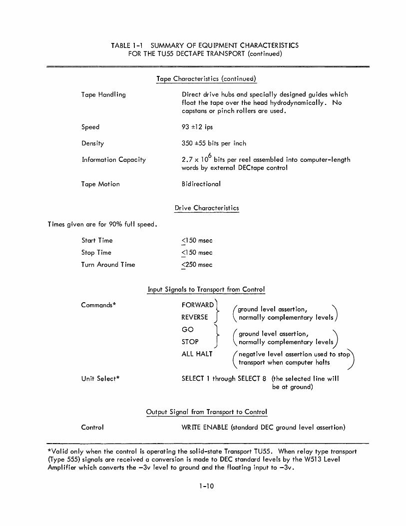
TABLE 1-1 SUMMARY OF EQUIPMENT CHARACTERISTICS FOR THE TU55 DECTAPE TRANSPORT (continued)
Tape Handling
Speed
Density
Information Capacity
Tape Motion
Tape Characteristics {continued}
Direct drive hubs and specially designed guides which float the tape over the head hydrodynam ically. No capsta ns or pi nc h ro II ers are used.
93 ±12 ips
350 ±55 bits per inch
2.7 x 10⁶
bits per reel assembled into computer-length words by external DECtape control
Bidirectional
Drive Characteristics
Times given are for 900/0 fuH speed.
Start Time
Stop Time
Turn Around Time
Commands*
Unit Select*
Control
<150 msec
<150 msec
<250 msec
Input Signals to Transport from Control
FORWARD}
REVERSE
GO } STOP
ALL HALT
(ground level assertion, \ normally complementary levels)
(ground level assertion, '\ normally complementary levels)
(negative level assertion used to stop\ transport when computer halts )
SELECT 1 through SELECT 8 (the selected line will be at ground)
Output Signal from Transport to Control
WRITE ENABLE {standard DEC ground level assertion}
*Val id only when the control is operating the sol id-state Transport TU55. When relay type transport (Type 555) signals are received a conversion is made to DEC standard levels by the W513 Level Amplifier which converts the -3v level to ground and the floating input to -3v.
1-10

CHAPTER 2
THEORY OF OPERATION
2.1 BLOCK DIAGRAM ANALYSIS
The TU55 logic is shown in the functioncll block diagram of figure 2-1. All front panel con
trols and indicators are shown within the blocks representing the associated logic. The functions of these
controls and indicators are summarized in table 3-1. Diamonds indicate the direction of signal flow be
tween blocks; an open diamond represents a signal effective (asserted) at ground; a closed diamond rep
resents a signal asserted at -3v. All interface signals are received from or transmitted to an external
DECtape control system. One of the two connectors at the left of figure 2-1 serves as a command and
information signal bus to other TU55s.
A5 A6 r""".
lr.. ~
-
AB2 r--,
~
~
,. -
r"I
__ t...... WRITE ENABLE ~
1 WRITE
SELECT SELECT ENABLED
ADDRESS LOGIC ....... B ....... -(8)
~
II WRITE
~~ RIGHT BRAKE
JAND LOCK AND
r-' I "-TDELAY(I~ I SELECT .-:J AND:
LEFT BRAKE
1 I DELAY ( 1)
~ I ---SELECTED STOP TORQUE ....... MOTION (0) ...... _- (~ .- REMOTE --. ~.
__ r- GO B EfFf3 .- RIGHT ..... GO -:1 OR L FULL TORQUE .....
'--/
AB3 r""".
~
DIRECTION ( 1 ) MOTOR STOP ."....
_FWD ~_J ......
DRIVER ~
LOCAL ~
I DRAGTO'3~
FORWARD ..... AND ~ MOTION (I)
REVERSE MOTION
ALL_~ CONTROL AND GO DRAG TORQUE DIRECTION (0) REV ..... .-- -:1 OR I FULL TORQUE LEFT
L ~-MOTOR
I "JANOI ~
STOP TORQUE .... DRIVER
- ..... SELECTED ~
~-
SKEW MEAS. (!) ~
TMG (4) ,.TMG (4) ~
MR~( (4) HEAD jt1RK (4)
DATA' (4) RELAY .Jl...ATA '(4) HEAD -
DATA 2 (4) JJATA 2 (4) -,.DATA 3 (4) ~ATA 3(4)
'-----
NOTE: An arrow signifies a nonstandard DEC signal, such as motor voltage, head playback, brake voltage, etc.
In the motion contro~ block the arrow above a switch means that pressing this switch results in tape movement in this indicated direction when the middle switch is in the LOCAL position.
Figure 2-1 DECtape Transport TU55 Block Diagram
2,-1
, REEL
RIGHT
LEFT
REEL
The SELECTOR LOGIC block in figure 2-1 includes the front panel thumbwheel selector
shown in figure 1-1. This selector has nine positions (designated 1 through 8 and OFF LINE) for selecting
one of eight select lines which are the outputs of a binary-coded-decimal decoder in the external DEC
tape control system. During addressing, only one of the eight input select I ines is at the asserted
ground. In remote operation, the SELECT output is asserted negative whenever the thumbwheel setting
corresponds to the asserted address I ine from the DECtape control system.
Writing is possible on a selected drive only when that drive furnishes control with a WRITE
ENABLE signal at ground. A selected TU55 furnishes such a signal when the WRITE ENABLE switch in
figure 2-1 is on. When this switch is set to WRITE LOC K, the output I ine is negative and writing can
not take place. If the control is commanded to perform a write function when WRITE LOCK is selected,
it displays a selection error flag t.o notify the program of the mistake.
The five motion commands from the external DECtape control system are shown entering at
the left center. The ALL HALT signal is asserted negative by the external control whenever the computer
program execution is halted either by the program or by the operator. When the program is halted, the
computer cannot issue commands to peripheral equipment. The ALL HALT signal stops those transports
that were in motion at the time of the ALL HALT command, thus preventing a complete run-off of the
tape.
The other four commands, GO, STOP, FORWARD, and REVERSE, are asserted at ground by
the external control in response to computer program commands. In current DECtape controls, GO and
STOP are complementary levels. In the following discussion, the GO, STOP, FORWARD, and REVERSE
I ines referred to are at the output of the signal interface module (B07).
Tape motion begins at a selected TU55 when the GO I ine is asserted (STOP must be held
talse throughout the desired interval of tape motion). Motion stops whenever the STOP line is asserted
w~ile the GO line is simultaneously held false.
The same conditions as above apply to the FORWARD and REVERSE lines. For a selected
transport which is set to REMOTE, asserting the FORWARD I ine (while holding the REVERSE I ine false)
c:auses all subsequent remote GO commands to move tape forward. Similarly, asserting the REVERSE
line (while holding the FORWARD line false) selects the reverse direction. In LOCAL operation, the
reverse and forward tape-motion switches override the last REMOTE direction command so that the tape
cJlways moves in the direction of the arrow above the switch (see figure 2-1).
Current DECtape controls generate the GO/STOP and the FORWARD/REVERSE signals as
c:omplementary levels. Forward tape motion, for example, is commanded by assertion levels on GO and
FORWARD accompanied by false levels on STOP and REVERSE.
When forward motion is commanded either locally or remotElly, the,motion control logi,e asserts
the FWD output negative. This signal releases both brakes and appl ies full clockwise torque to the right
2-2
motor and partial counterclockwise torque to the Ileft motor. As a result the tape moves from the left
reel across the head onto the right reel. The REV I ine (asserted negative in response to the REVERSE
motion command) appl ies full torque to the left motor, partial torque to the right motor, and simulta
neously releases both brakes. Tape motion, therefore, is from right to left. At the end of either com
mand, the STOP I ine is asserted negative and triggers the stop delay (about 100 msec). For the
duration of the delay, full torque is applied to the trailing motor and stop torque is applied to the
leading motor (see section 3.3). Thus, for the duration of the delay after the STOP command has
been issued, the motor torques are reversed causing tape movement also to be reversed. This time,
however, is very short and when the delay times out, the motors come to zero speed while changing
their rotation from one direction to the other. After the STOP DELAY times out, the tape becomes
motionless and partial torque is applied to both reels to take up the tape slack and the brake is appl ied
to the motor shaft which was trail ing during the previous motion. The effect of the delay is null ified
if a new motion command is given before the end of the l-sec interval. Then, the torque signals to the
left and right motor drives are immediately reestabl ished according to the new motion command. The
delay starts again at the leading edge of each STOP signal regardless of the frequency of its occurrence;
i. e., no recovery time is inherent in this type at delay.
An illustration of the t'ape head is shown in figure 2-2. Every channel consists of two tracks
associated with their coils. When writing, the current flows from ground (center tap) through one of
the coils {to either + or - terminal)to saturate the tape in one direction and through the other coil to
saturate the tape in the other direction. The coils for the two tra,cks are wired in series and are brought
out as four I ines: ground, +', -, and the shield. 'Nithin the head, relay module, the +, -, and ground
lines (center taps) for a channel are switched by cIne of five 3-pole, normally open reed relays. Shields
are not switched, but are through-connected from the head to the interface connectors. A separate
I ine from the tim ing channel (also shown in figure 2-2) is brought out to allow measurements of head
skew (or the head perpendicu larity). This I ine is used only for test purposes (and not by the external
control). The single head-ground line is used to !~round the head case.
2-3

22 PIN AM PHENOL PLUG
I~
\
TRACK I
TRACK 2
N S
SHIELD
TRACK 10 - TIMING
TRACK 9 - MARK
N S
SKEW CENTER CHECK TAP
A D - TIMING
J - MARK V
R
TRACK 3
TRACK 4
TRACK 5
N S
TRACK 6 DATA I
TRACK 7 DATA 2
TRACK 8 DATA 3
N S
\ __ ______ 1
W
S
M
CENTER TAP
HEAD GROUND
- DATA 1
T - DATA 2
N - DATA 3
Figure 2-2 Head Connections
2.2 DETAILED DESCRIPTIONS
This section describes, in detail, the flow of information and control through each of the
functional elements of the TU55 control unit. The discussion is I imited to describing the various
modules as logical operators. Detailed descriptions of individual circuits are given in section 2.3,
Module Descriptions.
The basis for the discussion in the remainder of this section is the block schematic in DEC
drawing BS-D-TU55-0-2. This drawing is subdivided into zones bounded by horizontal section A
-through D and vertical section 1 through 8. Circuit locations are referenced by a letter-numeral
Icombination. For other drawing symbology, refer to the introductory paragraphs of chapter 5.
2.2.1 Interface
All interface signals received or transmitted by the tape motion control circuits are trans
ferred between the TU55 and the external DECtape control system. Interface signals for the tape
motion control logic consist of: eight unit select input lines, five command input lines, and selected
write enable output control I ines. Bus connections for these signals from the DECtape control system
jro the TU55 are made by plugging a FLIP CHIP cable connector into module receptacles (A5 or A6).
These signals together with the power I ines and the information I ines (to be described under Read/Write
Head Circuits) constitute the interface for the entire TU55.
2-4
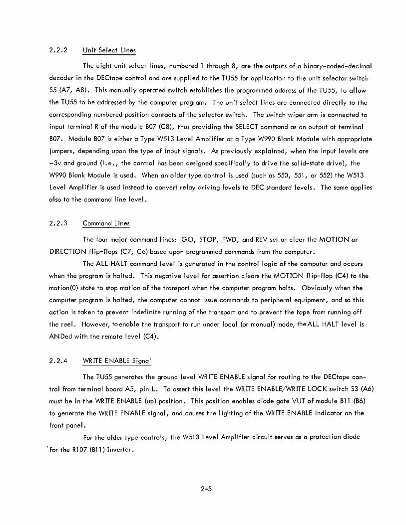
2.2.2 Un it Se I ect Li nes
The eight unit select lines, numbered 1 through 8, are the outputs of a binary-coded-decimal
decoder in the DECtape control and are supplied to the TU55 for application to the unit selector switch
S5 (A7, A8). This manually operated switch establ ishes the programmed address of the TU55, to allow
the TU55 to be addressed by the computer program. The unit select I ines are connected directly to the
corresponding numbered position contacts of the selector switch. The switch wiper arm is connected to
input terminal R of the module B07 (C8), thus providing the SELECT command as an output at terminal
B07. Module B07 is either a Type W513 Level Ampl ifier or a Type W990 Blank Module with appropriate
jumpers, depending upon the type of input signals. As previously explained, when the input levels are
-3v and ground (i .e. j' the control has been designed specifically to drive the solid-state drive), the
W990 Blank Module is used. When an older type control is used (such as 550, 551, or 552) the W513
Level Ampl ifier is used instead to convert relay driving levels to DEC standard levels. The same appl ies
also to the command I ine level.
2.2.3 Command Lines
The four major command lines: GO, STOP, FWD, and REV set or clear the MOTION or
DIRECTION flip-flops (C7, C6) based upon progrclmmed commands from the computer.
The ALL HALT command level is generclted in the control logic of the computer and occurs
when the program is halted. This negative level for assertion clears the MOTION flip-flop (C4) to the
motion(O) state to stop motion of the transport when the computer program halts. Obviously when the
computer program is halted, the computer connot iissue commands to peripheral equipment, and so this
action is taken to prevent indefinite running of the transport and to prevent the tape from running off
the reel. However, toenable the transport to run under local (or manual) mode, theALL HALT level is
AN Ded with the remote level (C4).
2.2.4 WRITE ENABLE Signal
The TU55 generates the ground level WRITE ENABLE signal for routing to the DECtape con
trol from terminal board A5, pin L. To assert this level the WRITE ENABLE/WRITE LaC K switch S3 (A6)
must be in the WRITE ENABLE (up) position. This position enables diode gate VUT of module B11 (B6)
to generate the WRITE ENABLE signal, and causes the I ighting of the WRITE ENABLE indicator on the
front pane I.
For the older type controls, the W513 Level Amplifier circuit serves as a protection diode
I for the Rl07 (B11 ) Inverter.
2-5

2.,2.5 Interface Connections
Information I ines are brought to the read/write head from the DECtape control system where
they are bussed together for connection to other transports. Connections to this bus from an individual
TU55 are made by cable connections of module connectors ,(A4 and B4). These connections are wired to
the Type GS51 Relay Module (A4, B4) for connection to the read/write head when the relay is operated
by the (SELECT) signal amplified by solenoid driver ER of the Type W040 Module (B4).
2.2.6 Read/Wr ite Head
A type GS51 Relay Module (A4, B4) establ ishes connection to the read/write head from the
information bus I ines of the DECtape control system. This module consists of 5 x 3 single-pole, normally
open contacts which are closed when the relay is energized. The relay is energized when the TU55 is
selected, thus connecting the read/write head channel coils to the control.
2.2.7 Tape Motion Control
Tape movement and direction of movement are controlled by two Type R202 Flip-Flops; namely,
stc)p/go MOTION flip-flop (C6) and a reverse/forward DIRECTION flip-flop (C7). The flip-flops are
set or cleared by command signals originating in the DECtape control system or in the reverse tape-motion
and forward tape-motion switches on the front panel (see Figure 1-1).
2.2.S Remote or Programmed Contro I
The four major commands that originate in tbe DECtape control system are GO, STOP, FOR
WARD, and REVERSE. Type R111 Diode Gates (B4, B5, 86) NAND-and combine these commands with
the SELECT level within the TU55. The output of these gates is used to set and clear the MOTION and
DIRECTION flip-flops. Therefore, motion and direction are controlled only in the selected transport.
The TU55 receives these four major commands as direct connections from the DECtape control system.
The eight unit select I ines, designated 1 through S, (BS) are connected to appropriate positions of the
unit selector switch (A7, AS). The transport is selec,ted when the selected line coincides with the
position of the unit selector switch. The negative SELECT level is conditioned by LOCAL and SELECT
ground levels (B7) if the transport is switched to the local mode. Then computer-control selection of
the transport is not affected.
The magnitude of the load on the address I ine is examined by the external control during
selection to determine whether more than one DECtape transport is being addressed.
2-6
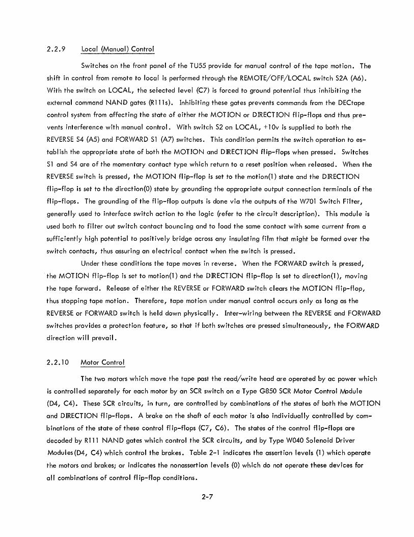
2.2.9 ~_ocal (Manual) Control
Switches on the front panel of the TU55 provide for manual control of the tape motion. The
shift in control from remote to local is performed through the REMOTE/OFF/LOCAL switch S2A (A6).
With the switch on LOCAL, the seiected level (C7) is forced to ground potential thus inhibiting the
external command NAND gates (R'111s). Inhibitin~J these gates prevents commands from the DECtape
control system from affecting the state of either the MOTION or DIRECTION flip-flops and thus pre
vents interference with manual control. With switc:h 52 on LOCAL, + 1 Ov is suppl ied to both the
REVERSE 54 (A5) and FORWARD 51 (A7) switches. This condition permits the switch operation to es
tablish the appropriate state of both the MOTION cmd DIRECTION flip-flops when pressed. Switches
51 and 54 are of the momentary contact type which return to a reset position when released. When the
REVERSE switch is pressed, the MOTION flip-flop is set to the motion(l) state and the DIRECTION
flip-flop is set to the direction(O) state by grounding the appropriate output connection terminals of the
fl ip-flops. The grounding of the fl ip-flop outputs is done via the outputs of the W701 Switch Filter,
generally used to interface switch action to the logic (refer to the circuit description). This module is
used both to filter out switch contact bouncing and to load the same contact with some current from a
sufficiently high potential to positively bridge across any insulating film that might be formed over the
switch contacts, thus assuring an electrical contact when the switch is pressed.
Under these conditions the tape moves in reverse. When the FORWARD switch is pressed,
the MOTION fl ip-flop is set to motion(l) and the DIRECTION fl ip-flop is set to direction(1), moving
the tape forward. Release of either the REVERSE or FORWARD switch clears the MOTION flip-flop,
thus stopping tape motion. Therefore, tape motion under manual control occurs only as long as the
REVERSE or FORWARD switch is held down physically. Inter-wiring between the REVERSE and FORWARD
switches provides a protection feature, so that if bClth switches are pressed simultaneously, the FORWARD
direction will prevail.
2.2.10 Motor Control
The two motors which move the tape past the read/write head are operated by ac power which
is controlled separately for each motor by an SCR switch on a Type G850 SCR Motor Control fvicdule
(D4, C4). These SCR circuits, in turn, are controlled by combinations of the states of both the MOTION
and DIRECTION flip-flops. A brake on the shaft of each motor is also individually controlled by com-
b inations of the state of these control fI ip-flops (CI', C6). The states of the control fl ip-flops are
decoded by R111 NAND gates which control the SCR circuits, and by Type W040 Solenoid Driver
Modules(D4, C4) which control the brakes. Table 2-1 indicates the assertion levels (1) which operate
the motors and brakes; or indicates the nonassertion levels (0) which do not operate these devices for
all combinations of control flip-flop conditions.
2-7
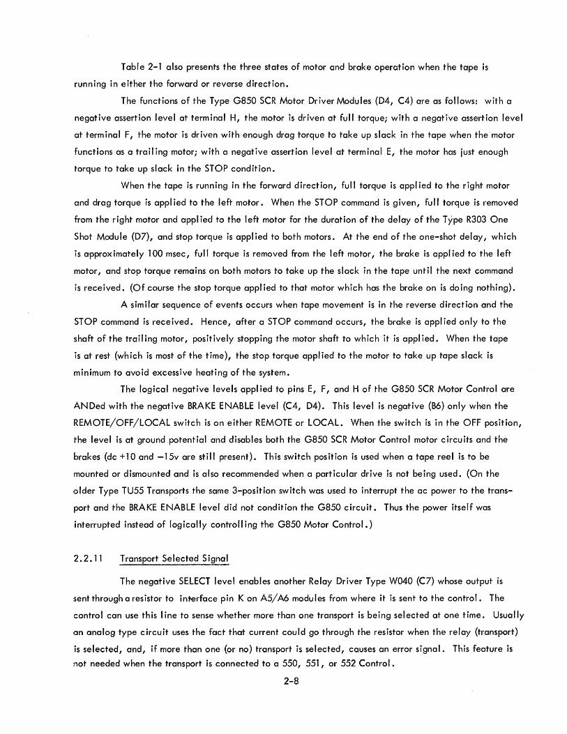
Table 2-1 also presents the three states of motor and brake operation when the tape is
running in either the forward or reverse direction.
The functions of the Type G850 SCR Motor Driver Modules (D4, C4) are as follows: with a
negative assertion level at terminal H, the motor is driven at full torque; with a negative assertion level
at term inal F, the motor is driven with enough drag torque to take up slack in the tape when the motor
functions as a trail ing motor; with a negative assertion level at terminal E, the motor has just enough
torque to take up slack in the STOP condition.
When the tape is running in the forward direction, full torque is appl ied to the right motor
and drag torque is appl ied to the left motor. When the STOP command is given, fu II torque is removed
from the right motor and appl ied to the left motor for the duration of the delay of the Type R303 One
Shot Module (D7), and stop torque is applied to both motors. At the end of the one-shot delay, which
is approximately 100 msec, full torque is removed from the left motor, the brake is appl ied to the left
motor, and stop torque remains on both motors to take up the slack in the tape until the next command
is received. (Of course the stop torque appl ied to that motor which has the brake on is do ing nothing).
A similar sequence of events occurs when tape movement is in the reverse direction and the
STOP command is received. Hence, after a STOP command occurs, the brake is appl ied only to the
shaft of the trailing motor, positively stopping the motor shaft to which it is applied. When the tape
is at rest (which is most of the time), the stop torque applied to the motor to take up tape slack is
minimum to avoid excessive heating of the system.
The logical negative levels appl ied to pins E, F, and H of the G850 SCR Motor Control are
ANDed with the negative BRAKE ENABLE level (C4, D4). This level is negative (B6) only when the
REMOTE/OFF/LOCAL switch is on either REMOTE or LOCAL. When the switch is in the OFF position,
the level is at ground potential and disables both the G850 SCR Motor Control motor circuits and the
brakes (dc +10 and -15v are still present). This switch position is used when a tape reel is to be
mounted or dismounted and is also recommended when a particular drive is not being used. (On the
older Type TU55 Transports the same 3-position switch was used to interrupt the ac power to the trans
port and the BRAKE ENABLE level did not condition the G850 circuit. Thus the power itself was
interrupted instead of logically controll ing the G850 Motor Control.)
2.2.11 Transport Selected Signal
The negative SELECT level enables another Relay Driver Type W040 (C7) whose output is
:sent through a resistor to interface pin K on A5/ A6 modu les from where it is sent to the control. The
control can use this I ine to sense whether more than one transport is being selected at one time. Usually
Ian analog type circuit uses the fact that current could go through the resistor when the relay (transport)
is selected, and, if more than one (or no) transport is selected, causes an error signal. This feature is
not needed when the transport is connected to a 550, 551, or 552 Control.
2-8
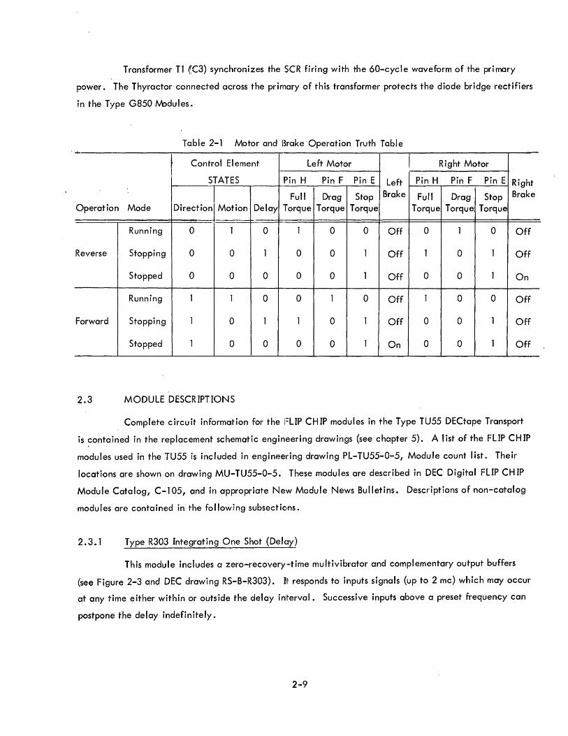
Transformer Tl (,C3) synchronizes the SCR firing with the 60-cycle waveform of the primary
power. The Thyractor connected across the primary of this transformer protects the diode bridge rectifiers
in the Type G850 Nodules.
Table 2-1 Motor and Brake Operation Truth Table ......
~ Control Element Left Motor Right Motor
STATES Pin H Pin F Pin E Left Pin H Pin F Pin E Right
DO ° 1M °
Fu" Drag Stop Brake Fu" Drag Stop Brake
Operation Mode Irectlon ot Ion Delay Torque Torque Torque Torque Torque Torque i
Running 0 1 0 1 0 0 Off 0 1 0 Off
Reverse Stopping 0 0 1 0 0 1 Off 1 0 1 Off
Stopped 0 0 0 0 0 1 Off 0 0 1 On
Running 1 1 0 0 1 0 Off 1 0 0 Off
Forward Stopping 1 0 1 1 0 1 Off 0 0 1 Off
Stopped 1 0 0 0 0 1 On 0 0 1 Off
2.3 MODULE DESCRIPTIONS
Complete circuit information for the FLIP CHIP modules in the Type TU55 DECtape Transport
is ~ontained in the replacement schematic engineering drawings (see chapter 5). A I ist of the FLIP CH IP
modules used in the TU55 is included in engineering drawing PL-TU55-0-5, Module count list. Their
locations are shown on drawing MU-TU55-0-5. These modu les are described in DEC Digital FLIP CH IP
Module Catalog, C-105, and in appropriate New Module News Bu"etins. Descriptions of non-catalog
modules are contained in the following subsectic,ns.
2.3. 1 Type R303 Integrating One Shot (DeIClY)
This module includes a zero-recovery,-time multivibrator and complementary output buffers
(see Figure 2-3 and DEC drawing RS-B-R303). Ij~ responds to inputs signals (up to 2 mc) which may occur
at any time either within or outside the delay inl~erval. Successive inputs above a preset frequency can
postpone the delay indefinitely.
2-9
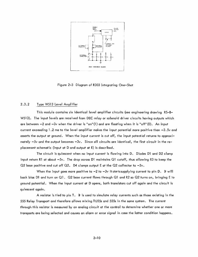
2.3.2
ENABLE GATE INPUT
5
I: 1. H I JUMPER FOR
~' U~
EXTERNAL r- -1 INTERNAL 400 NSEC RHEOSTAT I Co" RHEOSTAT PULSES
Lw~~;
1-·
R P N M L
EXTERNAL I 1 1 1 1 CAPACITOR ~!f r 12 13 14 T'
R401 VARIABLE CLOCK
Figure 2-3 Diagram of R303 Integrating One-Shot
Type W513 Level Amplifier
This module contains six identical level amplifier circuits (see engineering drawing RS-B
W513). The input levels are received from DEC relay or solenoid driver circuits having outputs which
are between -2 and -3v when the driver is "on Jl (1) and are floating when it is "offll (0). An input
current exceeding 1 .2 ma to the level ampl ifier makes the input potential more positive than -3. 5v and
asse~rts the output at ground. When the input current is cut off, the input potential returns to approxi
mately -5v and the output becomes -3v. Since all circuits are identical, the first circuit in the re
placement schematic (input at D and output at E) is described.
The circuit is quiescent when no input current is flowing into D. Diodes D1 and D2 clamp
input return R1 at about -5v. The drop across D1 maintains Q1 cutoff, thus allowing R3 to keep the
G~2 base positive and cut off Q2. D4 clamps output E at the Q2 collector to -3v.
When the input goes more positive to -2 to -3v it startssupplying current to pin D. It will
back bias D1 and turn on Q 1. Q2 base current flows through Ql and R2 so Q2 turns on, bringing E to
ground potential. When the input current at D opens, both transistors cut off again and the circuit is
quiescent again.
A resistor is tied to pin T. It is used to simulate relay currents such as those existing in the
555 Relay Transport and therefore allows mixing TU55s and 555s in the same system. The current
through this resistor is measured by an analog circuit at the control to determine whether one or more
transports are being selected and causes an alarm or error signal in case the latter condition happens.
2-10

2.3.3 Type G850 SCR Motor Driver
Essentially this module is an SCR switch for the ac voltage suppl ied to anyone of the drive
motors of' the TU55. The SCR switch is turned on and off twice during each cycle of the ac power. The
firing point of the SCR is controlled so that it can occur at almost any point along the sinusoidal wave
form of tlhe ac power; thus controll ing the amount of energy that is transm itted to the load (the motor),
and thus achieving control of motor torque. A siimpl ified schematic diagram of this module' is shown in
Figure 2-,4, a complete schematic in DEC engineering drawing RS-B-G850.
"'OVIA) o----~----__ ----____, r UI' L
1
0664 R2 00-+1- IOO,g~
I E O!l D6 D7
C GND I RI
<>-----11 15,000
i
I
5-' ..
R4 15,000 5%,
e-I~vo---f--~~--
R9
~
Re 15,000
5"'/0
i -~)CC i l'"' ':' 't~' (Y'fn -
! AO '''~ i::~ , L '-- ~ __ ~~-;~ 11[-- - - -oT .. I TERMINALS
I I I ~I I -~ ~B 1-B o----+-'--~
I Not part of G850 Schematic AC LINE I ~--------------------~
Figure 2-4 Schematic of G850 SCR Motor Driver
-3AT /I'1Pi-./E:i
H t=u LL.
D 16 ,= D~A6-IN 758
The SCR itself (015), is connected intc) a diode bridge so that current always passes though it
in the same direction (an SCR is not a bilateral d«9vice). The firing circuit for the SCR incorporates a
unijunction transistor (Q4) and an RC timing network. The capacitor (C 1) in this network starts to charge
at the beginning of each half cycle of the ac vollrage. When the voltage developed across the capacitor
reaches the firing point of Q4, conduc;tion starts and current flows in the primary of a coupling trans
former (Tl). Voltage induced in the secondary oir T1 controls the firing of the SCR and causes the motor
to operate.
Three input timing circuits determine the trigger timing of the SCR. A -3V level applied to
the two-diode input of these circuits cause the SCR to trigger at a fixed rate or a variable rate determined
by the setting of potentiometers R5 and R9. The Fixed input circuit (Q3) triggers the SCR near the
beginning of the sinusoidal wave to produce maximum torque.
A low voltage ac input is supplied to terminals U and V from the secondary at transformer Tl
of the TU55 logic (not T1 of the module). This input voltage is full wave rectified and is clipped by a
2-11
Zener diode I but is not filtered. It provides the potential toward which the timing circuit attempts to
charge. Being a stepped down version of the primary ac power which operates the drive motors I this
voltage synchronizes the firing of the SCR to the line frequency. Since the voltage at the end of each
half cycle is zero, the RC network must start charging at the end of each half cycle. Therefore I this
pulsating voltage causes the SCR to fire each half cycle at a point in time measured from the zero
voltage point.
CAUTION
Be very careful when handling this circuit or probing it for measurement purposes since it contains 115v ac. A short circuit caused by a probe could produce a high current. Do not tamper with this module without first disconnecting power from the back terminal.
2-12

3. 1 INTRODUCTION
CHAPTER 3
OPERATION
As stated in chapter 1, the TU55 can be operated in either a local (manual) or a remote (auto
matic-programmed) mode. Local operation is accomplished by use of the controls and indicators on the
front panel of the equipment. Remote operation is effected through programmed commands produced by
the stored program of the computer. The following paragraphs contain information applicable to both
modes of operation.
3.2 CONTROLS AND INDICATORS
The functions of the controls and indicators on the control panel in figure 1-1 are summarized
in table 3-1. Additional information of the action initiated by the controls is given in the following
paragraph.
3.2.1 Operating Notes
When the REMOTE/OFF/LOCAL switch is in the OFF position, the REMOTE indicator does
not light but the TU55 logic sti II responds to selection, control, and command signa Is from externa I con
trol. Consequently the externa I control may select and attempt to read or write tape but no tape motion
takes place. In all normal modes, this condition idles both the DECtape control system and TU55 because
no timing channel signa I is made available from a motionless tape. When the system is commanded to
write on the timing and mark channels, the timing pulses are generated within the external control per
mitting the control to operate as if tape motion wen;~ avai lable.
3.3 L.OADING TAPE
To mount a reel of DECtape on the TU55 after energizing the equipment, proceed as follows
(see figure 1-1 and table 2-1):
To load tape set the REMOTE/OFF/LOCAL switch to the OFF position. This releases the brake
and inhibits the operation of the G850 SCR Motor Driver circuits. Then the hubs are free to be loaded or
unloaded with tape reels. If a new reel is to be mounted, unreel about a foot of tape from it over the
guides and read/write head and wind the tape one or two revolutions onto the right reel. Turn the switch
to either LOCAL or REMOTE as is desired for the next operation.
3-1
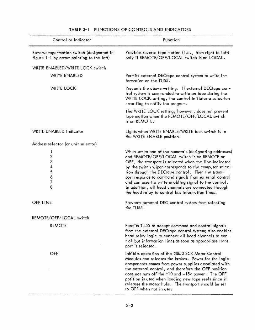
TABLE 3-1 FUNCTIONS OF CONTROLS AND INDICATORS
Control or Indicator Function
Reverse tape-motion switch (designated in figure 1-1 by arrow pointing to the left)
WRITE ENABLED/WRITE LOCK switch
WRITE ENABLED
WRITE LOCK
\'\fRITE ENABLED indicator
Address selector (or unit selector)
1 2 3 4 5 6 7 8
OFF LINE
REMOTE/OFF/LOCAL switch
REMOTE
OFF
Provides reverse tape motion (i.e., from right to left) only if REMOTE/OFF/LOCAL switch is on LOCAL.
Permits external DECtape control system to write information on the TU55.
Prevents the above writing. If external DECtape control system is commanded to write on tape during the WRITE LOCK setting, the control initiates a selection error flag to notify the program.
The WRITE LOCK setting, however, does not prevent tape motion when the REMOTE/OFF/LOCAL switch is on REMOTE.
Lights when WRITE ENABLE/WRITE lock switch is in the WRITE ENABLE position.
When set to one of the numerals (designating addresses) and REMOTE/OFF/LOCAL switch is on REMOTE or OFF, the transport is selected when the line indicated by the switch wiper corresponds to the computer selection through the DECtape control. Then the transport responds to command signa Is from externa I control and can assert a write enabling signal to the control. In addition, all head channels are connected through the head relay to control bus information lines.
Prevents external DEC control system from selecting the TU55.
Permits TU55 to accept command and control signa Is from the external DECtape control system; also enables head relay logic to connect a II head channels to control bus information lines as soon as appropriate transport is selected.
Inhibits operation of the G850 SCR Motor Control Modules and releases the brakes. Power for the logic components comes from power supplies associated with the external control, and therefore the OFF position does not turn off the + lOa nd - 15v power. The OFF position is used when loading new tape reels since it releases the motor hubs. The transport should be set to OFF when not in use.
3-2
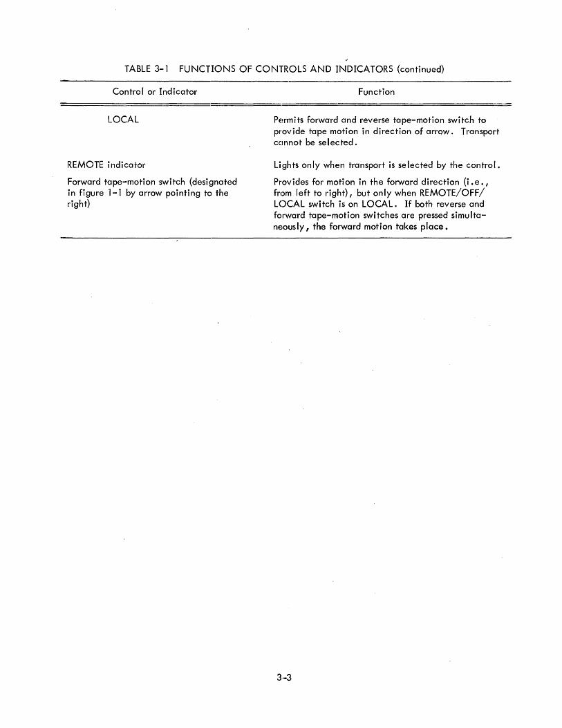
TABLE 3-1 FUNCTIONS OF CONTROLS AND INDICATORS (continued)
Control or Indicator
LOCAL
REMOTE indicator
Forward tape-motion switch (designated in figure 1-1 by arrow pointing to the right)
Function
Permits forward and reverse tape-motion switch to provide tape motion in direction of arrow. Transport ccmno't be selected.
Lights only when transport is selected by the control.
Provides for motion in the forward direction (i.e. I from left to right) I but only when REMOTE/OFF/ LOCAL switch is on LOCAL. If both reverse and forward tape-motion switches are pressed simultane,ously, the forward motion takes place.
3·-3


CHAPTER 4
M A I N T E NA N C E
4.1 EQUIPMENT REQUIRED
Maintenance activities servicing TU55 DECtape Transports require the equipment listed in
table 4-1 J' or the equ ivalent; pi us standard hand tools, cleansers, test cables, probes, etc.
TABLE 4-1 RECOMMENDED MAINTENA.NCE EQUIPMENT
Equipment'
Multimeter
Oscilloscope *
FLIP CHIP module extender
Small thin-bladed screwdriver
Phill ips-head screwdr ivers
Allen-wrench set
Man ufclcturer
Triplett or Simpson
Tektronix
DEC
Model
630-MA or 260
Series 540 or 580 with Type CA differential preampl ifier
W980
All four standard sizes
No. 667
* Head gain and head skew tests require a dual-b'9am oscilloscope such as Tektronix Type 550 or 551 with a high-gain differential preamplifier for each beam channel, such as Tektronix Type D. However, these tests are seldom necessary in the field.
4.2 PREVENTIVE MAINTENANCE
The following weekly and monthly preventive maintenance schedules are recommended to
forestall possible failures. Special emphasis is pktced on cleanliness of tape handling surfaces because
dust and oxide particles contribute to read errors.
4.2.1 Weekly Schedule
a. Clean entire front panel of tape deck.
b. Clean both surfaces of tape guides and tape head using an appropriate head cleaner
and a soft lint-free cloth.
c. Check proper operation of motor and reel brakes before loading tape by momentarily
pushing forward and reverse tape-moti()n switches on front panel.
4-1
4.2.2 Monthly Schedule
This schedule should be performed on each DECtape once a month when equipment operates
on a standard 8-hour shift and more often when daily operation exceeds one shift. Stagger the check
outs on individual transports evenly throughout each month.
a. Clean the exterior and interior of the cabinet using a vacu~m cleaner and clean cloths
moistened, if necessary, in nonflammable solvent.
b. Clean air filters at the bottom of bay using procedure given in PM section of maintenance
manual for DECtape control system.
c. Lubricate door hinges, casters, etc., with a light machine oil.
d. Inspect equipment for completeness and general condition. Repaint scratched or corroded
areas.
e. Make sure each FLIP CHIP module is securely seated in its mounting panel connector.
f. Run a complete exercise and diagnostic routine for each transport so that both the trans
port and its associated control are exercised in all possible modes and in both directions.
Maintenance programs for this purpose are available from DEC for all computer/control/
transport DECtape systems. Appl icable programs are I isted in the maintenance manual for
the DECtape control system. Log all errors to provide a malfunction history as an aid to
troubleshooting. If tape is slack or bounces during exercises, perform the adjustment and
calibration procedures in the next subsection.
g. Rotate tapes among all transports and use the read routines of the maintenance programs
to be sure that all transports can read tapes generated by other transports. If each transport
operated satisfactori I y in step f, any malfunctions in this step are probably due to head skew.
Head skew can be measured by the procedures given later in the troubleshooting subsection
but cannot be adjusted in the fiel'd.
4.3 TAPE TENSION AND TRANSPORT STOP ADJUSTMENT
a. Set the R303 Integrating De lay to about 70 ns. Pin D in A04 of the delay is varied
with the aid of the trimpot mounted on the module.
Initiation of the delay is made by pressing momentarily on either the forward or reverse
switch when the REMOTE/OFF/LOCAL switch is on LOCAL. No tape reel is needed for
this operation.
4-2

b. Mount a tape reel on the transport. Press the forward switch and watch the tape move
ment. The trailing torque of the left motor should be adjusted on the G850 Module All
trimpot (as shown in figure 4-1). If the torque is too great it will impede the movement at
i"he tape; and if too little, flapping or loose contact with the read write head will result.
The technician who maintains the equipment might develop a "touch" so that by pressing
his finger over the tape at the trail ing reel he can tell if the tape is too tight or loose,
simply by the stiffness of the tape wh ile in motion.
c:. Repeat same procedure for reverse tClpe movement by pressing reverse switch. This
time the pot adjustment is done on modu Ie A 12.
d. Press forward switch for a second or two and release it; the tape action while stopping
should be smooth. If bounc ing occurs, iincrease the stopping torque until bounce just
disappears. This stop torque is maintained when the transport is not operating (which is
most of the time) and excessive torque merely results in overheating the motor and hence
the whole equipment. Torque adjustment is made on the appropriate pot (figure 4-1) on
module A12.
I~. Repeat same procedure when pressinH the reverse switch, watching for the stop when
tape movement is in reverse. Adjust pol" on module All.
POT FOR DRAG TORI:;)UE
ADJUSTMENTS \
G250 MODULE
POT FOR STOP
/
(OR AT REST) ADJUSTMENTS
Figure 4-1 Module Adjustment Trimpots
4.4 HEAD OUTPUT CHECK
This check is used to determine whether the read-head is developing the proper read signals.
If the read-head performance is not satisfactory, the head should be replaced. No attempt should be
4-3
made in the field to repair or even change head position by loosening the brackets that hold it to the
plate. Although DEC personnel are authorized to replace heads in the field, the replacement involves
realignment and usually requires the return of the transport to DEC, Maynard. The following diagnostic
procedure can be performed with any single-channel oscilloscope having a high-gain differential pre
<lmplifier capable of handling signals in the millivolt range over a bandwidth of 0 to 60 kc, (Tektronix
Type D Plug-in Unit).
a. Mount a DEC certified tape on the TU55 Transport. Move tape manually in a forward
direction until approximately one half of the tape is on each reel.
b. Disconnect the 22-pin Amphenol head connector from rear of Head-Relay Module G851
located at the extreme right of the mounting panel seen from the rear. Attach the two probes
of the differential ampl ifier to pins Band C of this connector and attach the ground cl ip to
D. Set the oscilloscope to sync internal, and set the vertical preamplifier to 5 mv/cm
{0.5 mv/cm if an X10 probe is used}.
An alternative method is to cause a closure of the information relays by grounding {with the
aid of a clip} pin E of the G851 Module at location AB1. This eliminates disconnecting the
plug procedure, as outlined above, by making it possible to monitor the same plug points on
the wiring panel front. The probes are now attached to pins AF and AH of the same FLIP CH IP
socket AB1. The gound cl ip is attached to pin C.
c. Move tape forward and reverse using forward tape-motion switch and observe that the
read- head waveform is about 10 to 12 mv peak-to-peak.
d. Repeat step c,attaching the probes to pins F-H, P-R, U-V, and Y-Z. These signals may
not look sinusoidal {as they do for pins B-C}, but the peak-to-peak ampl itude should measure
the same as in step' c. The same alternative exists here as in step b. The pin pairs to monitor
now are: AN-AP, AV-BD, BH-BJ, and BN-BP.
iL5 HEAD-SKEW CHECK
Although the head-skew is not adjustable in the field, the following check should be performed
when unusual numbers of read errors are observed on an individual transport engaged in reading tapes
~~enerated by several other transports. The procedure requires a dual-beam oscilloscope with two high";
~~ain differential prea,mpl ifiers for each scope channel {as outl ined in the equipment needed,4.l}.
a. Write a timing track on a scratch tape using one of the DECtape utility routines.
4-4

b. Rewind tape back onto the left reel. Dismount the left reel from the left hub and mount
it on the right and mount the empty reel on the left hub. Thread tape over the head and onto
the left reel. Move tape in reverse to fill up the left reel. The tape is now with its oxide
foc i ng up away from the head.
c. Disconnect the 22-pin Amphenol head connector from rear of Head Relay Module G851 •
This module is located at the extreme right of the mounting panels, seen from the rear.
d. Connect the two upper-scope channe I probes to head connector pins A anq C and the ir
ground c I ips to the chassis. Connect the- two lower-scope channel probes to head connector
pins A and D and the ir ground c I ips to, the chassis. Set both channel preamps to A-B (the
differential setting).
e. Move tape forward by using the forward tape-motion switch. Adjust channel gain so
that each waveform has the same peak-tc)-peak voltage. Sync on the upper beam and take
a reading of the phase difference betwee!n,the signal peak at pins A and D (track 10) with
respect to the signal peak at pins A and C (track 1). Be sure to record whether the track
10 signal leads or lags the other and the amount. Make all readings as near the center of
the tape length <;IS possible. Skew readings greater than 5 ,",sec indicate possible incompati
bility among transports. Probably the head has become misaligned through physical damage.
Then the transport must be returned to DEC, Maynard, for realignment.
f. Remove all probes, reconnect the Arnphenol connector to the rear of the G851 Head
Relay tvbdule, and rewind the tape to the original state.
NOTE 1: It is possible here also to use the alternative method of monitoring the channel waveforms (see alternate method, section 4.4b) by energizing the relay at the G851 Wodule by grounding pin E. By doing so probe clips can be attached to the wiring panel pins at location A1. The pins are D-H for one probe and D-J for the other.
NOTE 2: In some heads (manufacturE~r, GJM) use pin F instead of pin H on the FLIP CH IP socket. On the Amph'~nol plug at the back use pin B instead of pin C.
4.6 WRITE ENABLE CIRCUIT CHECK
a. Set the WRITE ENABLE/WRITE LOC I( switch to WRITE position and check that the WRITE
ENABLE indicator lights. Also check that a ground level is present at terminals A5L and
A6L (C8).
4··5
b. Set the switch to the WRITE LOC K position and check that the WRITE ENABLE indicator
is extinguished. Also, check that level at terminals A5L and A6L is -3v. Check transmission
of this level from terminal A5L to the DECtape control system.
4.7 TROUBLESHOOTING
The forward and reverse tape-motion switches on the front panel of the TU55 are useful in
checking the operation of the unit and in assuring that the tape-motion mechanism is work ing properly.
It is suggested that the first step in troubleshooting should be a check of the modular logic circuits.
For this check, the primary ac power cable should be disconnected from the plug at the back
c:>f the transport to prevent movement of the tape drive motors. Set the REMOTE/OFF/LOCAL switch to
lrhe LOCAL position. Then simulate the commands to GO FORWARD and GO REVERSE by pressing the
(lppropriate switch. When the swi,tch is released, the STOP command is initiated to energize the left
motor shaft brake (the brake coii is energized from the -15v supply). Under these conditions, use an
oscilloscope or a voltmeter to compare the command signals throughout the logic circuits against those
iin table 3-1 •
This operation is checked by monitoring the terminals of the Type G850 Modules (All and
A12) and the Type W040 Modules (B12) with an oscilloscope of voltmeter to verify proper signal levels
for all operating conditions of the MOTION and DIRECTION flip-flops (B08). Then inspect the motor
hubs to check for proper operation of the brakes. This is accompl ished by assuring that the proper hub
stops when called upon to do so by the command logic (activated by operation of the front panel tape
motion switches).
If the truth table cannot be verified, continue troubleshooting by signal tracing, monitoring
the signal levels at different NAND gate inputs and outputs and working back toward the control flip
flops until the cause of the malfunction is found. If the truth table can be verified, restore the primary
ac input power, install a reel of tape on the drive mechanism, and repeat the truth table verification
procedure for proper tape movement and end stopping. If the ma I function sti II exists, check the
following sources of trouble:
a. Transformer Tl secondary is not presenting stepped down ac power to terminals U and V
of the modules All and A12 (the Type G850 SCR Motor Driver Modules).
b. Type G850 Modules are defective.
c. Electromechanical system (e.g. reel motor) rather than the control logic.
4-6

4.8 RECOMMEN DED SPARES
Table 4-2 lists the recommended spare parts for TU55 Transport systems. A R-series module
in the TU55 may be replaced by an S-series module with the same number. All items are available at
DEC, Maynard, but may be ordered from the other firms listed.
Part Number
G850
G851
R002*
R303'**
S107*
Slll'*
5202*
W040
W513***
W7011
MD/B570-O-ll-l-A
8132K20 G6V52
8132K22 G6V52
8137K21 G6V52
7533-7
MOT-1
B K-0001
TABLE 4-2 RECOMN\ENDED SPARE PARTS
SCR motor driver
Head relay
Part
Diode network
Integrat i ng one shot
Inverter
Diode gate
Dual flip- flop
Solenoid driver
Level ampl ifier
Input network
Rotary selector switch (address selector)
Rocker switch (REMOTE/OFF/LOCAL)
Rocker switch (WRITE E~~ABLED/LOCK)
Rocker switch (forward olnd reverse tape-, motion) (with off-nonmomentary on circuit)
Capacitor (reel motor), 7 mfd, 300 wvdc
Torque motor, 70-frame /' SP spec
Friction brake, FB-181-23 DEC spec
Manufacturer
DEC
DEC
DEC
DEC
DEC
DEC
DEC
DEC
DEC
DEC
DEC
Cutler-Hammer
Cutler-Hammer
Cutler-Hammer
Sangamo
Electric Indicator Co. (ELINCO)
Megatrol
* These modules are contained in the basic PDP-8 or the TC01 DECtape Control, so duplicate spare parts are not required if the TU55 is part of this system configuration.
** This module is contained in the TC01, so a dupll icate is not required if the TU55 is used with a TC01 DECtape Control.
*** This module is required only if the TU55 is not used with a TCOl DECtape Control.
4-7


5. 1 INTRODUCTION
CHAPTER 5
ENGINEERING DRAWINGS
This section contains reduced copies of the engineering drawings, (see Pertinent Documents
chapter 1) required for understanding and maintaining the Type TU55 DECtape Transport. These drawings
are in addition to the complete set of full-size drawings forwarded with each TU55. Only the full size
drawings should be used by maintenance personnel for work on the units. The full-size drawings show
variati ons pecu I iar to an indiv idua I insta IIation .
5.2 CIRCUIT SYMBOLS
The block schematics of DEC equipment are multipurpose drawings that combine signal flow,
logical function, circuit type and physical location" wiring, and other pertinent information. Individual
circuits are shown in block or semiblock form, using special symbols that define the circuit operation.
These symbols are similar to those apped'ring in the FLIP CHIP Module Catalog but are often simplified.
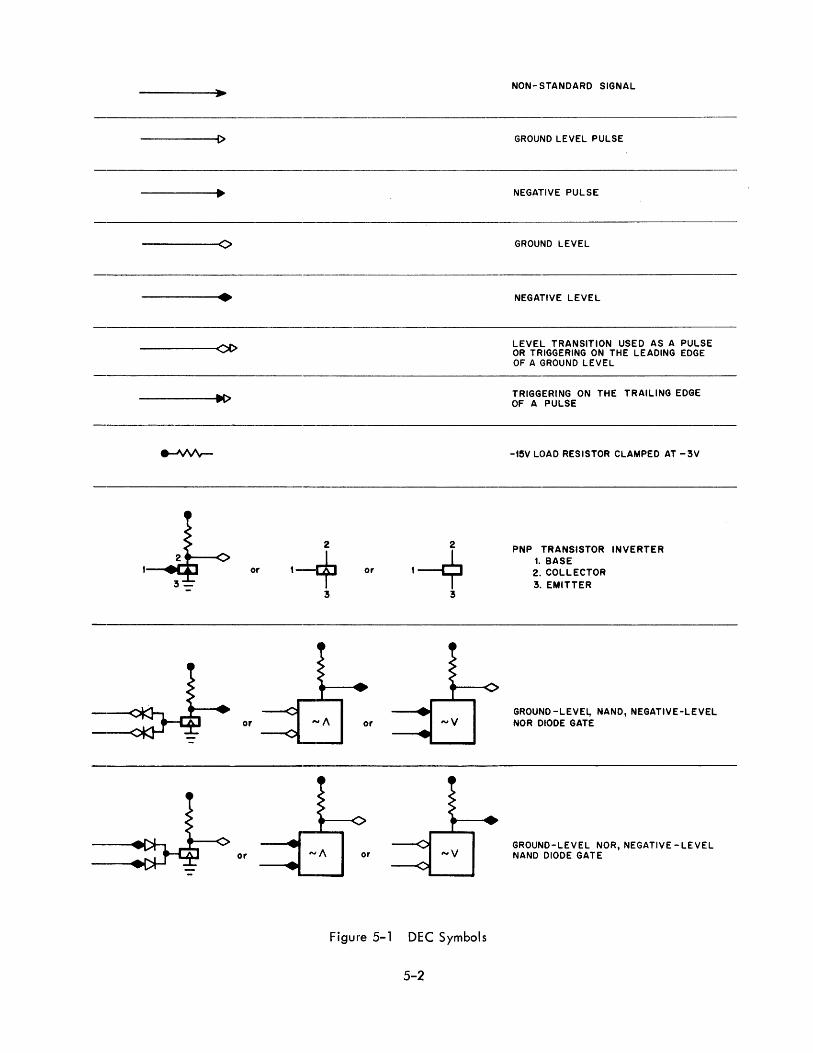
Figure 5-1 illustrates symbols used in DEC engineering drawings.
5.3 LOGIC SIGNAL SYMBOLS
DEC standard logic signal symbols are shown at the input of most circuits to specify the enabling
conditions required to produce a desired output. These symbols represent either standard DEC logic levels
or standard FLIP CHIP pu Ises.
5.3.1 Logic Levels
The standard DEC logic level is either at ground (0 to -0. 3v) or at -3v (- 2.5 to - 3 .5v).
Logic signals generally have mnemonic names which indicate the condition represented by assertion of the
signal. An open diamond (--t> ) indicates that the signal is a DEC logic level and that ground represerrts
assertion; a solid diamond (--. ) indicates that the signal is also a DEC logic level and that - 3v repre
sents asserf'ion. All logic signals appl ied to the conditioning level inputs of diode-capacitor-diode gates
must be present for a minimum of 400 nsec before an input pulse will trigger operation of the gate.
5.3.2 FLIP CHIP Pulses
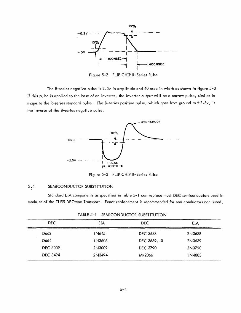
Two types of pulses, R series and B series, are used in FLIP CHIP circuit operation. The pulse
produced by R-series modules starts at - 3v, goes to ground (- O. 2v) for 100 nsec, then returns to - 3v.
This pulse is shown in figure 5-2.
5,-1
-----[)
-----0
• -----0[>
------I~
,~ 3-
or
2 ,-+ or I~ 3 3
or or .... v
or or
Figure 5-1 DEC Symbols
5-2
NON- STANDARD SIGNAL
GROUND LEVEL PULSE
NEGATIVE PULSE
GROUND LEVEL
NEGATIVE LEVEL
LEVEL TRANSITION USED AS A PULSE OR TRIGGERING ON THE LEADING EDGE OF A GROUND LEVEL
TRIGGERING ON THE TRAILING EDGE OF A PULSE
-t5V LOAD RESISTOR CLAMPED AT -3V
PNP TRANSISTOR INVERTER t. BASE 2. COLLECTOR 3. EMITTER
GROUND -LEVEl,. NAND, NEGATIVE-LEVEL NOR DIODE GATE
GROUND-LEVEL NOR, NEGATIVE -LEVEL NAND DIODE GATE
3
'-i 2 DIODE - CAPACITOR- DIODE
GATE
'-1 PA h: 8
o
2
+ DLY
3
4
3
'--i 2 CAPACITOR-DIODE
GATE
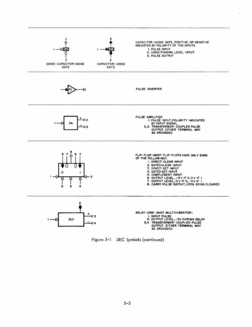
CAPACITOR -DIODE GATE, POSITIVE OR NEGATIVE INDICATED BY POLARITY OF THE INPUTS.
1. PULSE INPUT 2. CONDITIONING LEVEL INPUT 3. PULSE OUTPUT
PULSE INVERTER
PULSE AMPLIFIER I. PULSE INPUT, POLARITY INDICATED
BY INPUT SIGNAL 2,3. TRANSFORMER-COUPLED PULSE
OUTPUT. EITHER TERMINAL MAY BE GROUNDED
FLIP-FLOP (MOST FLIP-FLOPS HAVE ONLY SOME OF THE FOLLOWING):
I. DIRECT-CLEAR INPUT 2.GATED~LEAR INPUT 3. DIRECT-SET INPUT 4. GATED'SET INPUT 5. COMPLEMENT INPUT 6. OUTPUT LEVEL,-3V IFO,OV IF t 7. OUTPUT LEVEL, 0 V IF 0, -3 V IF t 8. CARRY PULSE OUTPUT, UPON BEING CLEARE'D
DELAY (ONE -SHOT MULTIVIBRATOR) I. INPUT PULSE
2. OUTPUT LEVEL,-3V DURING DELAY 3,4. TRANSFORMER - COUPLED PULSE
OUTPUT. EITHER TERMINAL MAY BE GROUNDED
FIgure 5-1 DEC Symbols (continued)
5·-3
10%
-0.2V .- - - r---......... - :l - - -
- 3V
l.--<400NSEC I
Figure 5-2 FLIP CHIP R-Series Pulse
The B-series negative pulse is 2.5v in amplitude and 40 nsec in width as shown in figure 5-3.
If this pulse is applied to the base of an inverter, the inverter output will be a narrow pulse, similar in
sh(]pe to the R-series standard pulse. The B-series positive pulse, which goes from ground to + 2 .5v, is
the inverse of the B-series negative pulse.
GND - - - --,-,
- 25V -- _.- ---1 PULSE r-- WIDTH -t1
OVERSHOOT
Fi gure 5-3 FLIP CHIP B-Series Pu Ise
5.4 SEMICONDUCTOR SUBSTITUTION
Standard EIA components as specified in table 5-1 can replace most DEC semiconductors used in
modu les of the TU55 DECtape Transport. Exact replacement is recommended for sem iconductors not listed.
TABLE 5-1 SEMICONDUCTOR SUBSTITUTION
DEC EIA DEC EIA
D662 1 N645 DEC 3638 2N3638
D664 1 N3606 DEC 3639,-0 2N3639
DEC 3009 2N3009 DEC 3790 2N3790
DEC 3494 2N3494 MR2066 1 N4003
5-4

8
D I
I MOTION (0) : R303 -!i ~ ~ -
1'1023 w023 A5 A6
STOP D GO IC
W513 GO F 807 STOP
D D
J LI~~L K r+ REV
FWD
FWO
REV
ALL HALT p",,~.j.'."'~: .. , , _ rl '----'-'-I (1..I.AVl ~
J
c
RI S
B T
U
i V I
8
UNIT SELEC TOR
A
8 7
6
DELAY(I) MOTION (I)
DIRECTION (I)
PWR UP OL Y
DIRECTION (I) D
OIRECTION(O) S
-slfs} I I 2 A A
I' I 3 .3
L L_' J
4--'~--------------~ FORWARD REM OFF LOCAL
MOTION (I)
I
~ WRITE
ENABLE
WRITi LOCK
l' /1
REAR VIEW SWITCH
6
'"--15\1--=--7 f-i
10 MFD-=
+IOV.±....j q JOMFD
5
STOP GO
W032 1'1032 AB2 AB3 (\ (\
I I~ V-~ AF !Ai lAl- lA..!:
I~ lAo AK IA.K
~ AN
I~ I!¥ IAF IAt AS IA.: AT AT
AU IAL ft..\1 IA.v
e,C lac ~E IBE BF Sf'
~RSE ~tH IB.!' Ia.. iBJ
~ a Iw Iat-J AN
5
4
-15V
I
AF
AH
AJ
AK
AN
AP
AR
AS
AT
AU
AV
80
BE
BF
BH
BJ
8L
8M
4
',,!;? v' eO, If .:
7·,.,p .... ,
'" (h(>-,;.t:·"h·'",{ ,c h.(,c s..",; 7'.
Pt,2\1..:PSi' ..®-O-·---'@.'i::"OnVUAR.D /;;;~... F~,." '~',: " ,4: R £:"':' _, ", "-
F" r f{ It· V f' '".><' , A. i'(: :t"'C(;<lj
I- +"c,. I
I*~-I 7 -UF D
I rffiB-1' LI __ _
3
t 3K 5W "* 7.uFD 3K
-~- ~I-~'
2
-1- - - -- -I
i
r+"*"-·+-t-I ~ }"OVAC , ,3LU
({HT ! '--=1 WH T
L ___ --1 'T+-tl-Hil"+--+.. ORN
IT! - GRN
ITRIAD F'3¢X
L_~O
ORN
ORN ORN
SYNC 1..
GRN r---------------------------------~--~~~~-+~ GRN
BLK THYP.ACTOR
GE-9~ 2OSP484
YEL --- --
'I I
.-J 'ED} ''0 "c
L--------------------+r-~~-IRED ~--~--------------------------------------------------~~--~~REO
I AC SYNC
NOTES:
I. 8!-2 SHAFT MOUNTED ELECTRO MAGNETS
BREAKS MEGATROL FBI81-24.
2. M 1-2 MOTORS ELiNCO, INDUCTiON TYPE.
3. M3 HOWARD FAN.
4. SI-4 CUTLER HAMMER MOMENTARY
SWITCH DPDT '*BI.37K2IG6V52
5. 53 CUTLER HAMMER
SWITCH OPOT BI32K22G6v52 (WITH NO
CENT. OFF POSITION.)
6. S2 CUTLER HAMMER DPOT ""Sl32K22G6V52
-/I; TAB TERMINAL,S ARE LOCATED ON CAPACITORS,
** LEVEL AMPLIFIER W513 IS USED \"IHEI\EVER THE
TRANSPORT IS CONNECTED TO A RELAY DRIVER TYPE
CONTROL) OTHERWISE USE 'N'390 MODULE WITH LUG WHICH SHQRT THE OUTPUTSTO RESPECTIVE
INPUTS.1JSE W990 WIT.H JUMPERS: D-E F-H J-K L-M N-P R-5 U-V
3 2
L
'TRA~S?ORT
;:ON~!S
I
I ID I
c
B
A
," 'xci' '-'t<:c· ~
.f""!",,,,
Sol id State DECtape Transport BS- D-TU55-0-2, Rev J
5-5
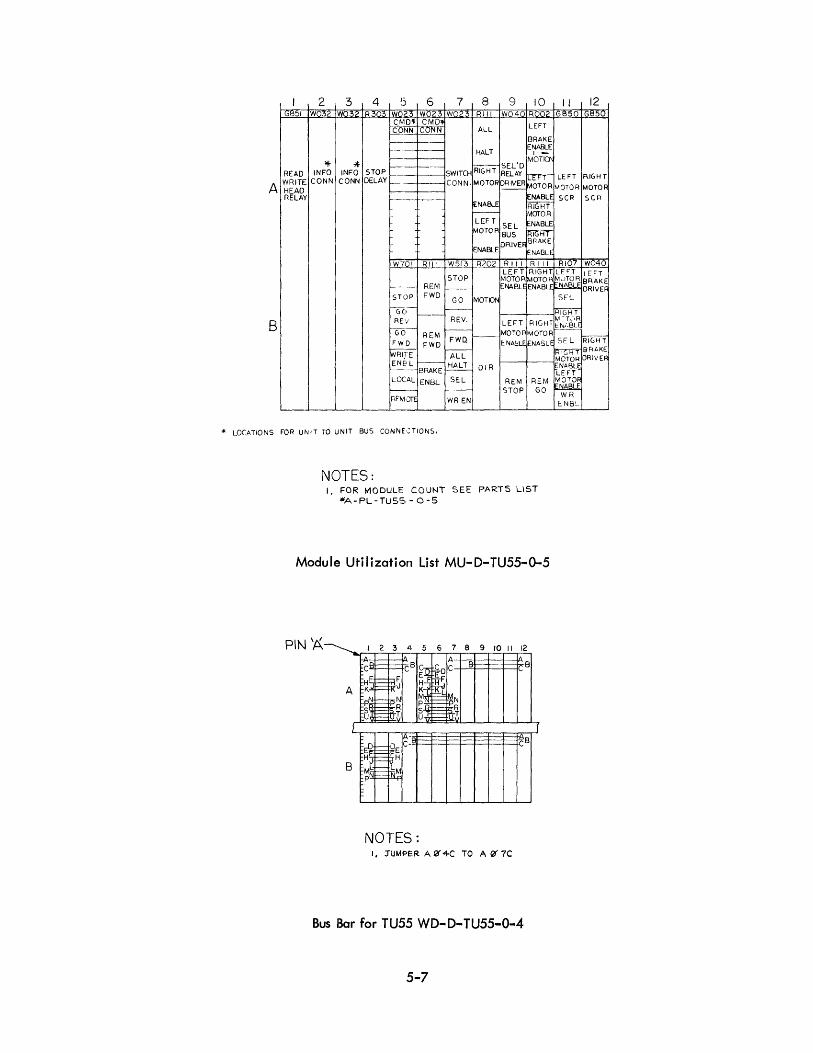
2 3 4 'S 6 7 8 9 10 .9~:'1 W032 W032 R303 W023 W023 W023 Rill W040 ROO2
CMDlI< CMD,. LEFT
~t:lli gJ~ ALL
-- -- BRAKE
-- - HALT ENABLE
* * IfiiG-HT SEL'D MC1=riQ.,
--READ INFO INFO STOP SWITo-t RELAY rrrr WRITE CONN CONN DELAY - CONN. MOTOR IoRIVER HEAD 1-MOTOR A RELAY NABLE
[ENABLE RiGHT ~ MOTOR LEF T
SEL NABLE ~OTOR BUS ~ ~NABLE
DF\lvE~ NABLE
W701 Rill W513 R202 Rill Rill LEFT RIGHT
STOP MOTOR MOTOR -- REM r----- NABLE ENABLE
STOP FWD GO MOTION
-G()- r-----B RE'/ REV. LEFT RIGHT
Ta- l--- MOTOR MOTOR REM FWQ I----
ENA5LE FWD FWD E:.NA(:U
~T I---ALL
ENE'L --I HALT DIR --- BRAKE LOCAL ENBL SEL REM REM ~-- I--- STOP GO REM,JrE WR EN
'" LOCATIONS FOR UNIT TO UNIT BUS CONNE,:TIONS.
NOTES: I. FOR MODULE COUNT SEE PARTS LIST
iIIIA-PL -russ - 0-5
Module Utilization List MU-D-TU55-0-5
PIN 'A 8 9 10 II 12
B
B
NOTES: I, :rUtr\PER A f1J4C TO A@' 7C
Bus Bar for TU55 WD-D-TU55-0-4
5-7
II 12 ,G850 GI::l50
LEFT F\IGHT
MOTOR MOTOR
SCR seR
RI07 W040 LEJOT LEFT
~')T~L~ BRAKE NA DRIVER SEl
'RIGHT ~:TC::·R IEr-,;.BL!
SE L ~GHT ~ BRAKE MOTOR DRIVER I';NABLE LEFT
~N%t~ WR
ENBc.
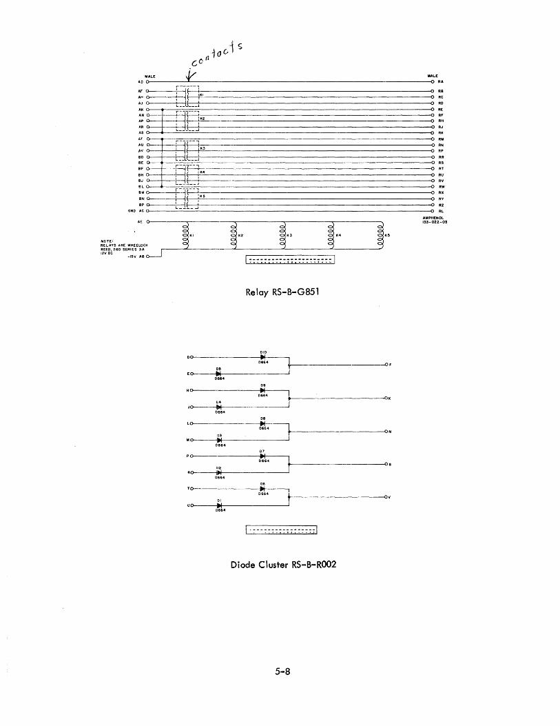
10 c;1 s Cc:(l
,Ii" MALE 'f' MALE AD O----------~------------------------------------------------------------------O RA
M O-------*:--~I(--:KI 0 RB A~O :1( 1 ORC AJ o~-----+L-_-Jls~_-_-_~J------'--------------------------------------------------------~o RO
AAA:RK:N~~~ __ -+~ ------------------------------------------------------0 RE
:~~--r_~[-~~Itr-:-J~IK-2------======--==--==--==--==--==--==--==--==--==--==--==--==--==--==--==--==--==--==--==--==--==:-~ :~ >---1------------------------------------------------------------------------~0 RK
AU ~o---~--=r~J~'--~-~,~---------------------------------------------------------------~ :: ,.11 Q---jr---T! --II ~ 0 RP
:~ o---r_~~-_~_L~-------------------------------------------------------------O RR 0 RS
BF ~ r-J~ __ -----------------------------------------------------------0 BH ~ : i ( I K4
RT
BJ ~_~ 0,------- --------------------------------------------------------0 RU
0 RV
BL ~ 0 RW
BMO ; IR-:--SNO : I~
0 RX
0 RY
BP o------i::-::it-£-_-..J'-I ----- 0 RZ GNO ACO----------------------------------------------------------------------------~O RL
AMPHENOL 133-022-03
NOTE. KI AE==r= RELAYS ARE WHEELOCK RHO, 260 SERIES 3A 1211 DC
-1511 AB
Relay RS-B-G851
DO----01164
~------------------------OF OS
EO a.I 0664
Olt
HO------------- a.I
,:~.------- --------------~OK 04
JO ~ 0664
08
Lo-----------t-I--~ 0664 ,---------1)3 ,
MO ~ oe&4
07
Po------------------;.~Ir-----, 0664
---~ON
.-----------------------~Os 1>2
Ro-----.~~I---------------' 0664
06
TO--- II'! D664
~------------------_______Oll 01
uo------.""~----------------~ 0664
Diode Cluster RS-B-ROO2
5-8
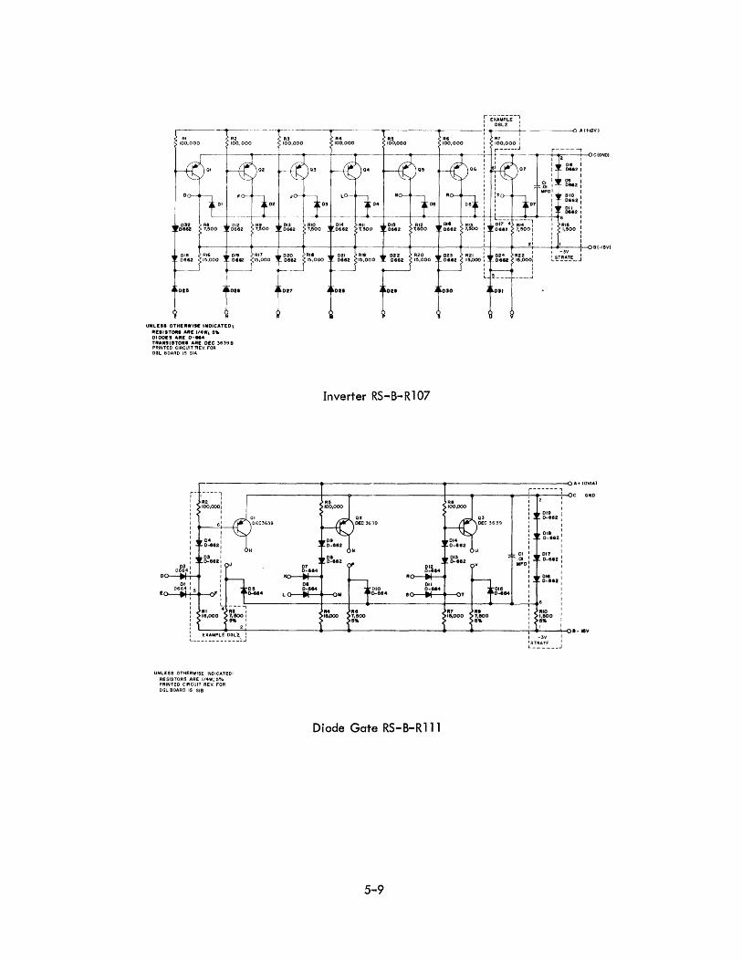
~--,---.---
RI R2
100,000 fOO' 000
,-- -~ QI _ Q2
'~+1,1 032 RI DI2
DHl! 7,500 0662
018 RI6 Of9 0662 15,000 0""
DU DZI
"NLESI OTHEII.,S[ INDICATED,
AEIISTOIII All' "" •• 5'" DIODES AilE 0-.... TIIANSISTOII' ARE DEC 3639B PRINTED CIRCUIT 'REV. FOR DOL BOARD IS SIA
Rl 100,000
R4 100,000
RS 100,000
RS 100,000
r-----, Z ~C(GNO)
08 1 [)66Z 1
1 09 1 DMZ 1
1
g~~2 : 0'1 I DU2 I
I
AI5 I 1,500 :
I
+------<~--f---+---+-t---+--~-----+, ...... ~-3V--+,-o B (-ISV)
R22: I ... S_T_R_AT_E_ ..J' 15.000!
~ ________ J
Inverter RS-B-R 107
r--------------_1>--------------_-------------oA+IOV(AI
r- ':;--1 J 100,0001 : I I 1
: 61
I I I 04 I
: 0 .. 11": I I
03 I I 0-111121
off .. : : I
01 I :
0-_06 .. 6
11-4
+-' 5,+-o~ :
i III ~ ;;- i le,ooo 7. eoo I
I K I
~ 2 I
L __ :~~~~L_E_~G~~J
UNLESS OTHERWISE INDICATED: RESISTORS ARE 1/4W; 5-/. PRINTED CIRCIJIT REV. FOR DGL BOARD IS SIB
r------, r--------~--~-----------+--~----.-~1~2___:_OC GNO
08 O-M4
07 D-811<!
08 0-....
01 0-1'"
114 le.ooo
Q2 O£C 36]9
IHO [I-8S4
012 0-814
011 0-814
Diode Gah! RS-B-Rlll
5-·9
013 0-1182
117 111,000
1
~:II" : I
g~866" : I
~~~'" : I
I
g~II" : 1 I I I
1 I I STRATE I L ______ ..J
1- leV

043
01
•• g~tl64 .~~~
U()--< , D!I 0-884
o!l,e40?i!4 O~ ... .. ...
: . .f~ ~~ 01
0lf.
III
,;~ "~O
V T
I
114 F~~I 100,000 5"4
-+-----<i~:__----+:__,_-__+----_+-__+-__oA+lOV
Dual Flip-Flop RS-B-R202
1111 1114 1110 11,000 4,POO 4,700 .11.
-
042 0-682
041 0-682
040 0-682
039 0-862
_-~+-~B-I&V
---0 A IOVI AI
, 'g~~84 ~O3 016 I ~'02' C G 0;.!,64
NO
01 DEC
~~ ~.~ .11.
'Oil
'010
II. III
t~ t,IOO ... I A
~ .... 0111
II. zo.ooo
·fJ ...,011
... ~;; F~z RI3
RI1 1119 IZ
~ 3,000 810 &"4
04 -:- ..... 01
~ 01
IIIZ illS .. 0 .10
;; Fce -feT *I~-fl .0Z7 •••• U at
K 1 I l 1·-----------------1 , . . . . ,.~ . '--- . ,
08 R22
~c~~ 3Ig.~O
011 0·664
III. .~ 3j)OO 15,000;5'11 5"4
1.s~~:'5'"
r--
1
RZI 1,!IOO 5"4
-~ D
Integrating One-Shot RS-B-R303
5-10
1,,027
AA~"j· I ~'O26
"025 3,0 100 ~"4 IIIIPO
CII r + CI2 .01 [email protected]
~~&-~
"018 '~:9 1"024
, 023 0864 664
I, OU
' 021
,.-----< r-- ..... 1124 R25 R28 11211 P.! 1,500 1,500 1.!lOO 880 680
1111. 5"4 5"4
B-15
H £ F
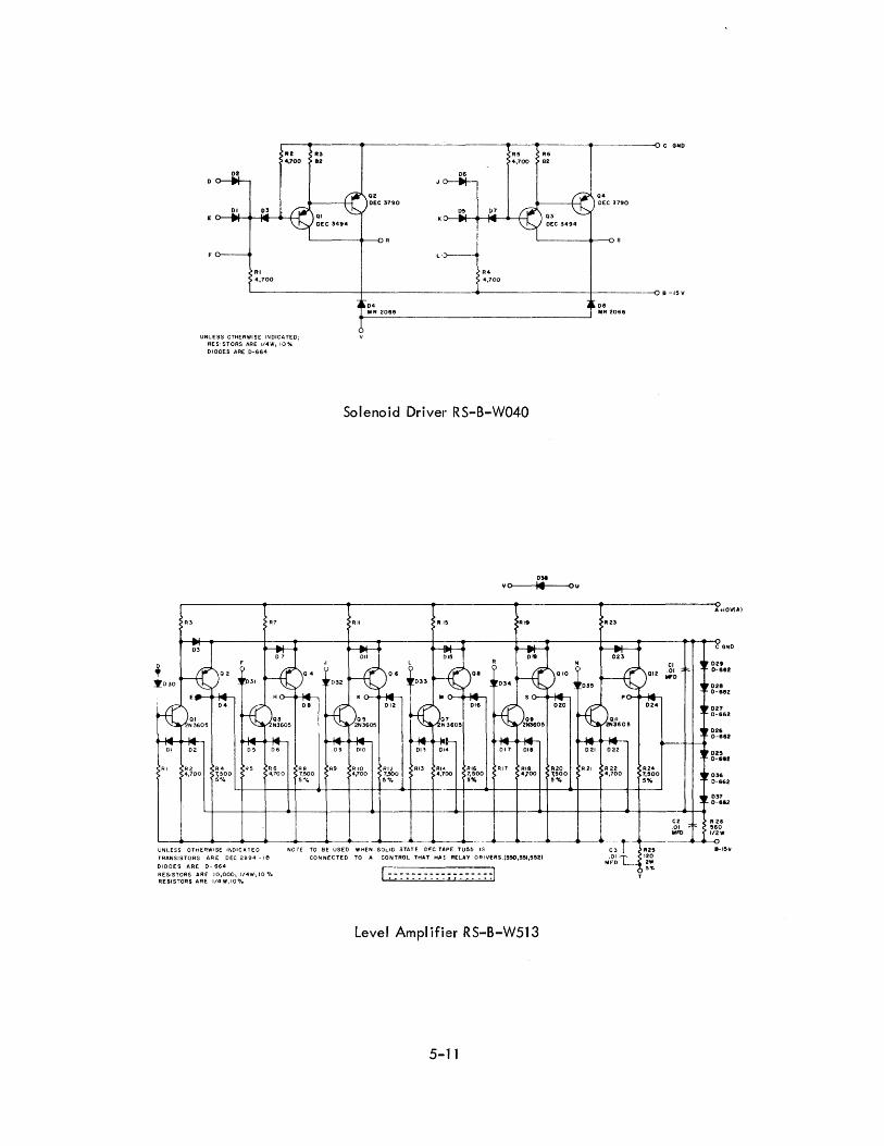
--------- -~.__----~ C GNO
02
01 03
RI 4,700
"Z R3 4,700 112
LI:>--
07
R4 4,700
R6 4,700 82
04 DEC 3790
---+-----.---0 B -15 V
UNLESS OTHERWISE INDICATED; RESISTORS ARE 1/4W .. 10-4
DIODES ARE 0-664
08 MR 2066
Solenoid Driver RS-B-W040
R3
R2 R4 R5 R6 R8 R9 RIO RI2 RI3 RI'" RI6 4,700 7;500 4,100 7,500 4100 1,:,00 4,100 7,~OO
5°/. 5 -I. 5~. 5%
I --4---
NorE TO BE USED WHEN SOLiD STATE DEC TAPE TU5~ IS
031 vo>---~I4I1----0 u
RI9 1123
RI8 R20 R21 R22 4,700 1,!'>00 4,700
!'>'Yo
UNLESS OTHERWISE INDICA TE 0
TRANSISTORS ARE DEC 2894 ~ Ie
DIODES ARE 0 .. 664
CONNECTED TO A CONTROL THAT H"'~. R[LAY DR!VERS.(5~,!'I!II,552)
RESISTORS ARE 10,000 .. 1/4Wi 10 -/0 RESISTORS ARE 1/4 W, 10%
Level Amplifier RS-B-W513
5-11
R24 1,!'>00 !'>'Yo
CI .01 ... 0
0 A.,OVlA)
C GNO
OU 0-SS2
0211 0-&62
027 0-662
026 0-1162
02!'> 0-662
036 0-662
037 0-11&2
R 26 !'>60 1/2W
8-1!'>1I

momooma
DIGITAL EQUIPMENT CORPORATION 0 MAYNARD, MASSACHUSETTS
Printed in U.S.A.