insulated case breakers - electrical part manual s
TRANSCRIPT
� l !
Instructions for Pneumatic
Operating Mechanism
Type AA-10-60 for Oil
Circuit Breakers
Westinghouse Electric Corporation Power Circuit Breaker Division, Trafford, Pa. I.B. 33-125-C5 Effective May, 1964 www .
Elec
tricalP
artM
anua
ls . c
om
TABLE OF CONTENTS
Description
PART 1 - RECEIVING, HANDLING AND STORING
PART 2 - DESCRIPTION . •
Description . • • • . . . • .
General . • . • • • • . . • . . .
Compressor and Air System. Pneumatic Mechanism and Control
Main Frame and Cylinder • •
Closing Piston Snubber . . . Retrieving Spring Assembly . Closing Piston Assembly Lever System • • . • • . . . • .
Trip Free Trigger . • • .
Trip Free Lever Stop . • .
Holding Latch and Trigger Trip Magnet Assembly Trip Selector . .
Control Valve • . . . • .
Control Scheme . . . . •
Low Pressure Cut-Out Scheme Reclosing Adjustment Switch Latch Check Switch . • . . . • . .
Accessories . • . . . • .
Auxiliary Switches . . Operation Counter . High Speed Switch . Heaters . . . . . . •
Hand Closing Device • •
Trip Free Locking Bar Mechanical Interlocks • •
PART 3 - OPERATION, AA-10
Closing . . • •
Opening • • .
Close-Open • •
Open-Close • •
Page
1
1
1 1 1 2 2 3 3 3 3 4 4 4 4 5 5 6 7 7 7
8 8 8 8 8 8 8 8
9
9 9 9
10
www . El
ectric
alPar
tMan
uals
. com
i i
TABLE OF CONTENTS - Continued
Description
PART 4 - INSPECTION, MAINTENANCE, ADJUSTMENT
Inspection . . . • • • • • . Maintenance • . • • • . • • • • •
Latches and Triggers . • . •
Air Leakages . . Overall • . . . . . Control Valve . Air Compressor . . Air Compressor Operation (Fig. 13)
Adjustments . . • • .
Pressure Gauge • • .
Pressure Switches . . Tripping .
Overtravel • • • . • •
PART 5 - TROUBLE SHOOTING SUGGESTIONS
A. If the mechanism fails to close the breaker B. If the mechanism closes the breaker,
but fails to keep it closed . . . . . . C. If the mechanism fails to trip . . . . . D. On Reclosing Duty, if the mechanism
trips but fails to reclose . . . . . .
Fig. No.
1 2 3 4 5 6
7-8 9-10
11-12 13 14
LIST OF ILLUSTRATIONS
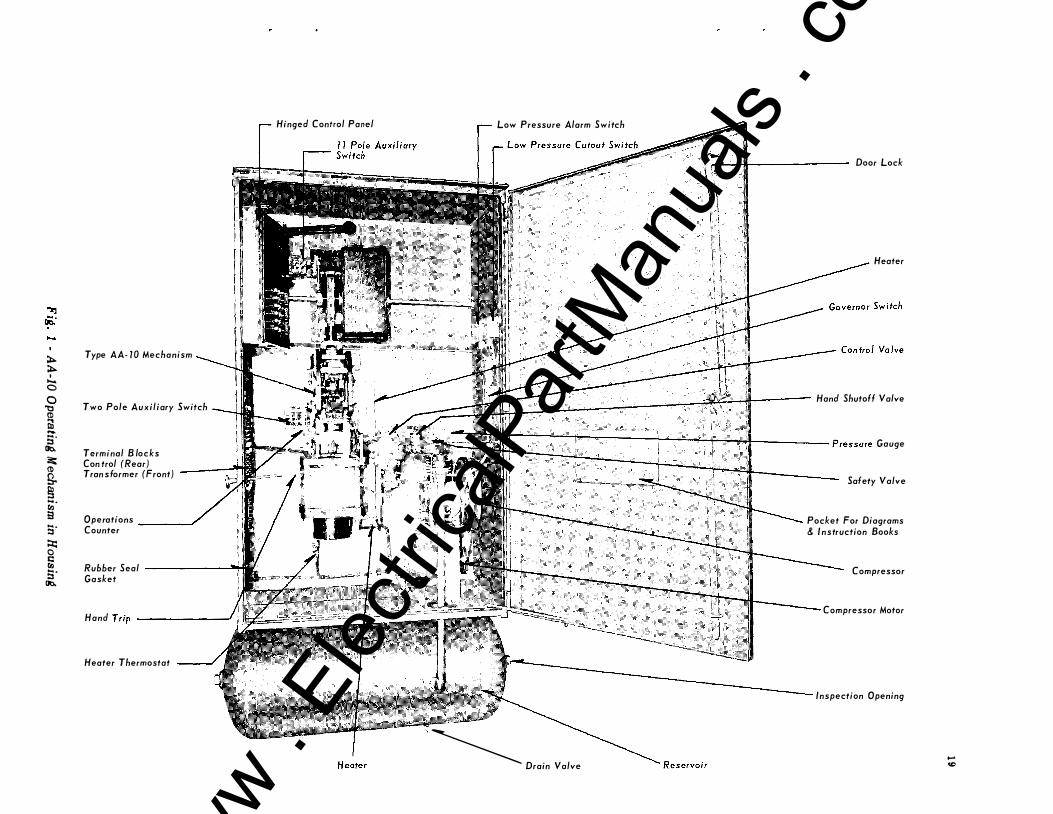
AA-10 Operating Mechanism in Housing •
Type AA-10 Mechanism . • • • • •
Open Position • • • •
Closed Position • • • .
Trip Free Position • • . • • • • • • • • •
Trip Magnet Assembly Control Valve • • • • • •
Air Schematic of Control Valve • • • • • • • •
Trip Selector Control • •
Air Compressor • •
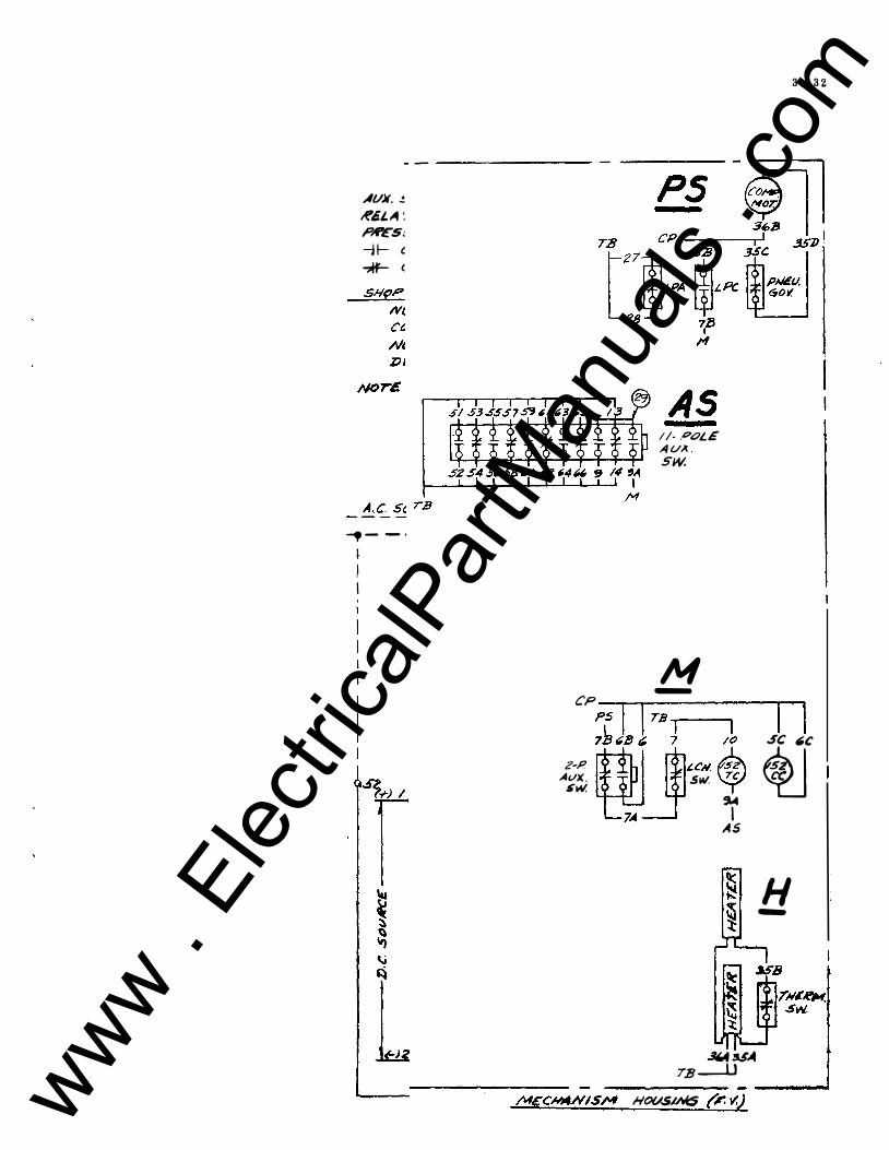
Schematic Diagram • • •
Page
10
10 10 10 11 11 11 13 14
14 14 14 15 16
16
16
16 17
17
Page
19 20
21, 22 21, 22 21, 22
23 25, 26 25, 26 27' 28
29 31, 32
""''"""'·
www . El
ectric
alPar
tMan
uals
. com
i i i
INTRODUCTION
Type AA-10 circuit breaker operating mechanism is closed
by compressed air, opened by springs, and is both electrically and
mechanically trip free. Since the closing energy is derived from
compressed air which can be stored up in a reservoir over a rel
atively long period of time with a low current consumption by
means of a motor driven compressor, the mechanism is especially
suited to applications where it is desired to eliminate large bat
teries required for solenoid mechanisms, or where fast reclosing
is required.
www . El
ectric
alPar
tMan
uals
. com

www . El
ectric
alPar
tMan
uals
. com
PART 1- RECEIVING, HANDLING, AND STORAGE Each mechanism and its associated
equipment is tested at the factory and should be in good condition when received. Inspection should be made immediately to see that no damage has occurred in shipment. If injury is evident, or indication of rough handling is visible, a claim for damage should be filed at once with the carrier (Transportation Company), and the nearest Westinghouse Sales Office notified promptly.
Unpacking should be done carefully to prevent damage, and all parts should be checked with the shipping list to insure against leavil)g any parts in the packing material. The mechanism should be accompanied by the proper identification tag and this instruction book.
Be sure to remove the blocks and wires which were used to hold moving parts, mechanism triggers and latches in place during transit.
PART 2- DES CRIPTION GENERAL
Included within the dust tight sheet metal housing are the following pieces of apparatus which combined with the air storage reservoir are designated as a complete operating mechanism:
(1) An air compressor, and the necessary attachments and accessories for con
trolling the air supply.
(2) A pneumatic mechanism consisting of the air cylinder and piston, a lever sys
tem for connecting the piston to the pull rod of the breaker and a system of latches for rapidly disengaging the breaker pull rod from the piston, a holding latch for maintaining the mechanism and breaker closed.
If the mechanism is not placed in service immediately, it should be kept in a clean dry place, protected from corrosion and moisture. This may be accomplished by closing the mechanism housing and energizing the space heaters provided in it. This procedure is recommended even if it requires the use of a temporary wire circuit to the heaters. In case this is impracticable, all machined parts, especially on the latching surfaces of the latch and rollers should be coated with grease or some rust inhibiting material. Additional protection may be obtained by the use of silica gel, activated alumina or similar dehydrating agents. Two or three small bags of the material should be hung in the mechanism housing near the parts requiring protection. It should be remembered that complete protection may not be provided in spite of all of the above precautions and periodic inspections should be made to-determine the condition of the apparatus.
(3) A control panel to provide the necessary relays and interlocks for remote
electrical control.
(4 ) A number of accessories essential to the proper functioning of the unit such
as a trip magnet assembly, control valve, auxiliary switches, a latch check switch, space heaters, thermostat, fused knife switches for the establishing and protection of the electrical circuits, and terminal blocks for terminating all wiring where it will be readily accessible for connections on installation. See Fig. 1.
COMPRESSOR AND AIR SYSTEM
The unit will consist of a 60 gallon reservoir, and a single stage (illustrated Fig. 1) com-www .
Elec
tricalP
artM
anua
ls . c
om
2
pressor. A pressure governor switch regulates the pressure in the storage reservoir. The pressure governor operates to start the compressor as soon as the pressure in the reservoir has dropped to a predetermined value, depending on the size of the circuit breaker to which the mechanism is applied, and stops the compressor as soon as the pressure has been raised to predetermined differential above the starting pressure. The pressure governor switch pressure settings are shown on the mechanism nameplate for each application. Power to operate the compressor is furnished by a 115/230 volt, single phase motor through a "V" belt drive. Unless the order specifically specifies differently, the motors when shipped will be connected for 230 V. a-c to prevent damage to the motor from overvoltage. D.C. or 3 phase motors may be supplied for special applications.
The reservoir tank fulfills the requirements of State Inspection Codes and all equipment is manufactured under A.S. M.E. requirements with close inspection. A safety valve is supplied to prevent the pressure from building up to a dangerous level, should the pressure governor switch fail to cut off the compressor motor.
At a pressure slightly above the minimum satisfactory operating pressure, a low pressure cut-off switch operates to open the closing circuit, thus preventing the mechanism from attempting to operate the breaker when there is insufficient air pressure to complete the operation. A seal-in interlock on the closing relay is wired in parallel with this low pressure cut-off switch so that should the low pressure cut-off switch open its contacts during a closing operation, the breaker will complete the closing operation. The minimum setting of the low pressure cut-off switch is set high enough above the actual minimum to insure enough air to complete the closing operation. The setting of all pressure switches and safety valves are made at the factory and should not need changing.
If anything should go wrong with the compressor or air equipment so that normal pressure is not maintained, a low pressure alarm switch is provided that can be used to sound an alarm indicating that the pressure is only slightly above the setting of the low pressure cut-off switch.
A hand shut off valve is provided in the air piping between the reservoir and the pneumatic mechanism that can be used as a safety measure to prevent accidental operation while working around the mechanism.
The schematic diagram for the air system is shown on Fig. 9 & 10. This diagram together with the control diagram, the various position figures, and the explanation of the mechanism operation should give a more complete understanding of the overall operation. The low pressure alarm and cut-off switches are connected to the mechanism side of the hand shut-off valve as an added safety feature, so that it is impossible to energize the closing control when the hand shut-off valve is closed.
PNEUMATIC MECHANISM AND CONTROL
The Type AA-10 is electrically trip free at all times and is mechanically trip free whenever there is air pressure in the main closing cylinder. The determination of whether the mechanism functions trip free or non trip free is accomplished pneumatically and is called selective tripping. Figs. 3, 4 and 5 illustrate and supplement the following description.
Main Frame and Cylinder
The mechanism is built up around the main frame which serves to support and enclose the levers, latches and triggers that provide the releasable connection between the closing piston and the breaker pull rod. The cylinder is attached to and supported on the www .
Elec
tricalP
artM
anua
ls . c
om
main frame by four bolts, and consists of a seamless tube clamped between the top plate which is part of the frame and the bottom plate.
Closing Piston Snubber
There are two concentric rings of rubber sandwiched between a recess in the top side of the bottom plate and a steel piston stop ring. These steel plates and the ring are given a corrosion resistant protective finish. This "sandwich" serves to absorb some of the final shock caused by the rapidly moving piston reaching the end of its travel. To decelerate the piston before engaging this resilient stop, a collar on the underside of the piston closes off a concentric, close fitting opening in the bottom plate as the mechanism approaches the closed position Fig. 4. This traps a small volume of air between the underside of the piston and the end of the cylinder providing pneumatic dashpot action.
Retrieving Spring Assembly
The retrieve spring housing and bottom plate are a one piece assembly. This assembly which clamps the cylinder to the main frame by four bolts, supports and encloses two heavy retrieve springs. The springs, which are compressed during the closing stroke, supply the force required to rapidly retrieve the piston to the open position whenever the mechanism is tripped.
Closing Piston Assembly
The main closing piston which is forged from a non-ferrous alloy is screwed on and locked to the piston rod at approximately its mid point. The lower end of the piston rod is threaded to receive the hand closing jack. An adjustable packing gland around the piston rod, plus a gasket between the mechanism frame and cylinder combined with two piston rings on the main closing piston mini-
3
mize the air losses during closing operations. The cross-head, which is located on the upper end of the piston rod, carries two pins: The upper pin "E" which is supported by roller bearings at either end, is engaged by the holding latch when the mechanism is in the closed position; the lower pin "B" serves to attach the closing lever to the piston rod, and extensions of this pin carry a roller at either end which travel between guide rails on the frame.
Lever System
The piston is connected to the breaker pull rod rod-end through the closing lever and thrust link which are joined with pin "C". The rod end and thrust link are joined by pin "A". The ends of this pin carry rollers which are guided between two rails and provide straight line motion of point "B". As long as point "C" is restrained to maintain the relative position of A-C-B as shown in Figs. 3 and 4, the movement of the piston will be transmitted to the breaker pull rod. If at any time during the closing operation or after the mechanism is closed, the restraint on point "C" is released, the linkage A-C-B will open up allowing the breaker pull rod and the closing piston to move independently of each other. This provides essentially the mechanically trip free function. The balance of the parts are required to make it possible to control at will the release or retention of the connection between the closing piston and the breaker, and also to reduce the load present at point "C" to a load on the trigger that will make possible low tripping effort. The intermediate link, which is connected to the thrust link and closing lever at one end by pin "C" and at the other end to the mid point on the trip-free lever by pin "D", transfers the load on "C" to the trip free lever. This creates a tendency for the trip free lever to rotate clockwise about the trip free lever fulcrum pin bearings. The trip free fulcrum pin is supported at either end in roller bearings. www .
Elec
tricalP
artM
anua
ls . c
om

4
Trip Free Trigger
The trip free trigger, which is positioned approximately tangential to the roller on the trip free lever and which is free to rotate on needle bearings about the trigger fulcrum pin, provides the final releasable means for controlling the fixation of point "C". The end of the trigger in engagement with the roller on the trip free lever is shaped in such a manner that there is a slight tendency for the trigger to rotate counter-clockwise whenever there is a load on the breaker pull rod. In addition to this moment the trigger is spring biased to the latched position as shown in Figs. 3 and 4. A stop on the trip free lever positions the end of the trigger accurately in respect to the roller insuring definite engagement.
To insure against the possibility of the shock incident to closing causing the trip free trigger to release the trip free lever prematurely, a spring biased catch is provided that engages the trip free trigger in the latched position. Normally there is no load on the catch, however the catch must be released prior to tripping the trip free trigger. An arm on the catch is interposed between the trip rod and selector bar which insures the prior release of the catch.
To insure positive latching with early cut-off of the closing air at the end of a closing operation, a spring biased catch, similar to the catch used in conjunction with the trip free trigger, is provided that engages the non trip free trigger as the trigger moves up behind the roller on the main holding latch. Normally there is no load on the catch, however the catch must be released prior to tripping the non trip free trigger. This release is accomplished by having an arm on the catch, extend over immediately behind the catch on the trip free trigger. Thus as the trip rod rises, it rotates both catches out of the way before the selector bar attempts to disengage either trigger.
Trip Free Lever Stop
The trip free lever accelerates rapidly to a relatively high speed in retrieving from the position shown in Fig. 5 to the open position Fig. 3. To stop this rapidly moving lever, a resilient stop is provided. The body of the stop is screwed into a cross bracing member of the main frame to provide adjustment of the stop. The resilient feature consists of a rubber plug totally enclosed in a steel housing. The outside diameter of the rubber is slightly smaller than the inside diameter of the housing which provides a relatively slow build up of resisting force until the plug has been deformed to fill the inside of the enclosure. The resisting force then builds up very rapidly to bring the trip free lever to rest.
Holding Latch and Trigger
In order to maintain the mechanism and breaker in the closed position after the closing air has been shut off, a sturdy holding latch, fulcrumed to the frame on roller bearings and spring biased toward the latched position is provided to engage pin "E" in the cross head. To provide for non trip free operation, which is required in order to realize high speed reclosing the nose of the latch is machined so that the breaker load at pin "E" creates a moment in a counter-clockwise direction on the latch. The latch is restrained in the latched position shown in Fig. 4 by the non trip free trigger, which is fulcrumed on needle bearings on the trigger fulcrum pin, and engages a needle bearing roller carried on the latch. The trigger is spring biased to the latched position shown in Fig. 4. The trigger stop pin serves to position the non trip free trigger in the latched position and also limits the overtravel of both the non trip free trigger and the trip free trigger in the tripped position.
Trip Magnet Assembly
The trip magnet assembly is located on the underside of the frame directly under the www .
Elec
tricalP
artM
anua
ls . c
om

selector bar. The trip rod is screwed into and locked to the trip armature. The upper end passes up through the stationary "E" frame to disengage the triggers, and the lower end extends down through a clearance hole in the resilient stop plate and carries a "kick-off" spring. The "kick-off" spring serves to force the armature away from the stationary core immediately after the trip coil is de-energized to insure rapid resetting of the triggers. 1/32" thick copper rivets on the underside of the pole faces creates a 1/32" air gap between the armature and pole faces which also speeds up the retrieving of the armature.
Trip Selector
In order to realize the benefits of short reclosing times made possible by non trip free operation, and still retain the advantages of fast tripping times obtained by mechanical trip free operation when closing in against a fault, it is desirable to be able to choose between trip free and non trip free operation. This is called "selective tripping" and is accomplished pneumatically as follows:- Reference Figs. 11 & 12. The selector bar, which passes at right angles to the planes of the two triggers and is interposed between the trip rod and the triggers has a boss on its upper edge so arranged that the length of the flat upper surface is greater than the spacing between the triggers. Thus the selector bar is always in a position to trip one or both triggers for any position of the selector bar. When the selector bar is over to its extreme left hand position, Fig. 12 the boss is directly under the non trip free trigger and a "valley" is under the trip free trigger. When the selector bar is moved over to its extreme right hand position, Fig. 11 the boss is directly under the trip free trigger and has been moved free of the non trip free trigger. The chamfer on the left hand end serves to prevent the selector bar from accidently interfering with the triggers during the transfer motion. The position of the
selector bar is determined by a spring bias that selects the non trip free trigger except when there is air pressure in the closing cylinder. A selector piston located in the control valve on the cylinder side of the inlet valve is connected through a linkage with the selector bar so that whenever the inlet valve is open, the selector piston will shift the selector bar over to the right and select the trip free trigger for tripping. With the inlet valve closed, the spring bias on the linkage returns the selector bar to its normal position for tripping from the non trip free trigger.
Control Valve
The control valve assembly combines both the inlet and exhaust functions in a single compact unit and consists of a main valve operated by an electro pneumatic pilot valve as illustrated in Figs. 7 & 8.
Certain illustration liberties were taken in Figs. 7 & 8 to facilitate the illustration and understanding of the valve construction and operation.
The solenoid pilot valve is double acting i.e. , when the inlet seat is closed, the exhaust port is open. The pilot valve inlet has a composition to metal seat and is spring biased closed. The valve is opened either by energizing the pilot valve coil or by manually operating the pushbutton on top of the coil which in both cases moves the valve stem down and opens the valve. The valve remains open only while the coil is kept energized or the button held down. As soon as the coil is de-energized or the button is released, the spring bias closes the inlet seat and opens the exhaust seat.
The main control valve is double acting also, (when the inlet seat is closed the exhaust seat is open) this blocks the high pressure air from entering the mechanism cylinder and at the same time allows the air in the cylinder to exhaust to atmosphere.
5
www . El
ectric
alPar
tMan
uals
. com
6
As shown in Fig. 7 the operating piston and exhaust poppet seat have a common body. The inlet poppet is driven by a stem attached to the operating piston poppet. The inlet seat is held tightly closed by a spring bias and the air pressure acting upon the under side of the inlet poppet. This also holds the exhaust poppet open and operating piston to the top of its bore.
The operating piston is sealed by an "0" ring which is held captive by a groove in the piston. The inlet and exhaust poppet seats are "0" rings which are held in place by spinning an edge of the poppet over the side of the "0" ring.
When the pilot valve is opened, it allows high pressure air to enter above the operating piston, forcing it down. (The pilot valve receives its air supply through an internal passage in the main valve body). Thus it closes the exhaust seat and opens the inlet seat allowing the air to flow to the mechanism cylinder. When the pilot valve is closed, the air from above the operating piston is exhausted and allows the exhaust seat to open and the inlet seat to close. The air flows from the control valve to the mechanism cylinder via an adapter, This adapter is cast of a non-ferrous alloy. Its principal function is to direct the flow of air to the cylinder unrestricted. The adapter, however, also provides a means for mounting the piston and cylinder which serve to actuate the trip selector. (Figs. 11 & 12) The air which operates the selector piston is taken from the adapter casting directly above the entrance to the mechanism cylinder. This insures that the selector piston will be responsive to the air pressure conditions of the closing cylinder. The piston and stem are one piece. The spring bias for positioning it in the retrieved position is on the selector lever. When the control valve is opened, the admission of air to the closing .cylinder simultaneously puts air pressure on the selector piston which overbalances the spring bias and shifts the selector linkage.
Control Scheme
To provide for remote and semi-automatic control of the admission of air to the mechanism, and the cutting off of the air at the end of a closing operation, a control panel is included as part of the standard equipment. The steel panel which is located on the left hand side of the sheet metal housing in order to provide the maximum unrestricted working space around the mechanism, is mounted on hinges enabling the panel to be swung out providing convenient access to the wiring on the rear. The equipment on the standard panel includes a closing relay, a cut-off relay, and three fused knife switches. Referring to Diagram Fig. 14, the closing relay designated as "X" and the cut-off relay designated as "Y" are pictured in the de-energized position. The arrangement of the two relays as shown provides an electrically trip-free; non-pumping device and is commonly designated as an X -Y control scheme.
The electrically trip-free feature is provided by inserting an auxiliary switch contact designated as "aa" in the cut-off relay coil circuit, and a circuit opening contact of the cut-off relay in the closing relay circuit. The auxiliary switch known as the cut-off switch is mounted on the pneumatic mechanism and connected by a switch operating lever to an extension of the cross-head roller pin. Thus the position of its contacts are determined by the position of the mechanism closing piston. On a closing operation, as the mechanism approaches the closed position, the "aa" switch makes up its contact energizing the cut-off relay coil, and this in turn opens the cut-off relay contact in the closing relay coil circuit, which returns the closing relay to the de-energized position, Simultaneously the multiple normally closed cut-off relay contacts in the pilot valve coil circuit open. To provide the non-pumping feature, a normally open cutoff relay contact is connected in parallel with the cut-off switch "aa" contact, and another normally open cut-off relay contact is con-www .
Elec
tricalP
artM
anua
ls . c
om
nected in parallel with the low pressure cutoff and latch check switches. If the mechanism and its connected load fail to remain closed, as the cut-off relay contact in parallel with the "aa" contact remains closed maintaining the closing circuit "locked out". The closing circuit will continue to be "locked out" until the operator releases the control switch de-energizing the control circuit.
Low Pressure Cut-Out Switch
To insure against the mechanism attempting to close when there is insufficient air pressure in the reservoir to complete the operation, a low pressure cut-out switch, has its contact connected in the closing circuit. The low pressure cut-out switch contact is normally closed, but opens before a critical operating pressure is reached.
To further insure against the low pressure cut-out switch opening its contacts during a closing operation, a "make" contact of the closing relay is provided in parallel with the low pressure cut-out switch. As soon as the closing relay is energized, the "make" contact "seals itself in" and insures the admission of air to the mechanism to complete the closing operation. This "seal-in" contact also insures the completion of any closing operation once started, even though the operator might release the control switch before the mechanism has had time to complete the operation.
Should it be desirable to speed up the reclosing time beyond the adjustment provided in the adjustable contact fingers on the 2 pole switch, a connection between "Y" and "MAG" on Fig, 14 can be made which eliminates the "X" relay pick-up time, Multiple contacts of the cut-off relay are also placed in this same circuit in order to speed up the deenergizing of the intake valve at the conclusion of the closing stroke as much as possible, and thus minimize the consumption of the stored compressed air per operation.
7
One of the fused knife switches on the control panel is provided to take the power off from the closing circuit locally during maintenance periods and also to provide overload protection, Another fused knife switch is provided for the same reason for the compressor motor circuit. The third fused knife switch is provided in the heater circuit.
Reclosing Adjustment Switch
Reference diagram Fig. 14. For reclosing duty, besides the addition of a reclosing relay such as the Type SGR-12 shown, an auxiliary switch indicated as "bb" on the diagram and located in the circuit from the recloser to the control relays is required. This switch, normally open when the mechanism is closed, is capable of adjustment so that the point in the opening stroke at which it makes up its contact can be varied. The setting of this switch controls the amount of opening of the breaker before reclosing and consequently determines the reclosing time. The "bb" contact is located on the 2 pole auxiliary switch and has adjustable finger contacts for varying the switch setting.
Latch Check Switch
Reference diagram Fig. 14. To insure that the mechanism is completely retrieved and the trip free trigger is fully engaged before any closing or reclosing operation (2nd or 3rd reclosure on multiple reclosing) is attempted electrically, an auxiliary switch indicated as LCH (latch check) on the diagram and located in the circuit between the closing circuit at the mechanism and the lead coming from the point of remote control is provided. This switch is operated mechanically by an extension on the trip free trigger and is normally closed except while the trigger is disengaged.
For applications where the Type AA-10 mechanism is used for multiple reclosing www .
Elec
tricalP
artM
anua
ls . c
om
8
duty, the switch determines the reclosing time by requiring that the energizing of the closing circuit be delayed until the mechanism is fully retrieved and the trigger reset following a trip-free o p e r a t i o n of the breaker.
ACCESSORIES
Auxiliary Switches
In addition to the 2 pole cut-off switch, an 11 pole auxiliary switch with independently adjustable contacts is provided for use in interlocking, indicating, alarm and trip circuits. The 11 pole switch is connected to the vertical pull rod and hence indicates the position of the connected load or breaker.
Operation Counter
An operation counter is mounted on the cutoff switch, and is operated by the switchoperating arm. The counter records on the opening stroke.
High Speed Switch
A high speed switch is available on special request which mounts on the mechanism housing back and is operated from the vertical pull rod.
Heaters
Two heaters are provided in the mechanism housing. One of these heaters is to be energized continuously winter and summer to maintain a temperature differential between the inside and outside in order to prevent undesirable moisture condensation within the housing. The other heater thermostatically controlled, is suitably located to provide better heat distribution in colder weather.
Hand Closing Device
A removable ratchet type jack hand closing device, which attaches to the lower threaded end of the piston rod and is supported by the underside of the spring housing, is provided for closing the mechanism and its connected load during adjustment of the breaker. This device is not to be used for emergency manual closing of the breaker on a live line.
Trip Free Locking Bar
A trip free locking bar is provided which when inserted through two holes in the side plates on the frame prevents the breaker from being tripped trip free. The bar passes behind the two catches and just above the tail section on the trip free trigger thus preventing trip free tripping.
Caution
The trip free locking bar does not prevent non-trip free tripping of the mechanism and consequential opening of the breaker. To prevent accidental tripping under all conditions apply both the hand closing jack and the trip free locking bar, and in the case of breakers with mechanical interlocks on the hand trip, first disconnect the hand trip rod from the bracket which lifts the trip armature, and then insert the trip free locking bar.
Mechanical Interlocks
Mechanical interlocks are supplied when there is the requirement for locking the breaker in the open position. On breakers furnished with mechanical interlocks, when tripping by pulling the hand trip knob, the selector bar is moved to the trip free position and the breaker will open fast to full open trip free. The mechanism can then be locked open by the key interlock while the hand trip is held in the tripped position. www .
Elec
tricalP
artM
anua
ls . c
om

PART 3- OPERATION CLOSING
Starting with the mechanism and breaker in the open position (Fig. 3) with the trip free trigger engaged to restrain the trip free lever, closing the control switch energizes the closing relay "X" and in turn the pilot valve coil "MAG", reference Fig. 14 which admits compressed air stored in the reservoir to the closing cylinder. The trip free trigger by restraining the trip free lever maintains the thrust link and closing lever in the relative position shown in Fig. 3 which effectively connects the closing piston to the breaker pull r:od. When the breaker is nearly closed, the "aa" auxiliary switch contacts close energizing the cut-off relay "Y" which simultaneously (1) opens its "Y" contacts in the pilot valve coil circuit initiating the shutting off of compressed air to the closing piston, (2) opens its contact in the closing relay circuit causing the "seal-in" contacts "X" to open and (3) closes the "seal-in" "Y" contact in parallel with the "aa" switch and the "Y" contact in parallel with the low pressure switch to maintain the closing circuit locked out until the control switch is released. The point where the "aa" switch makes up its contact is so near the end of the closing stroke, that the mechanism and breaker continue on in to the fully closed position before the closing air is actually shut off. As the mechanism reaches the fully closed position (Fig. 4) the holding latch engages the cross-head pin and the non trip free trigger engages the roller on the holding latch, keeping the mechanism and breaker closed. The closing air in the cylinder is exhausted and the selector bar shifts back to its normal position setting up the non trip free trigger for the next tripping operation.
OPENING
Starting with the mechanism in the closed position (Fig. 4) when the control switch or protective relay energizes the trip coil circuit, the trip rod on the moving armature of
9
the trip magnet disengages the non trip free trigger which has been restraining the holding latch to keep the breaker closed. Since the trip free trigger remains in engagement with the trip free lever, the piston remains connected to and is retrieved with the breaker to the open position Fig. 3. The two strong retrieving springs under the piston help to accelerate the piston and hence contribute partially to the opening speed of the breaker.
CLOSE-OPEN
Starting with the mechanism in the open position (Fig. 3) as the air pressure builds up in the cylinder following opening of the inlet valve, the selector piston shifts the selector bar to set up the trip-free trigger ready for tripping. Tripping the mechanism by the protective relay as the breaker contacts touch, (Fig. 4) disengages the trip-free trigger which releases the tripfree lever. A projection on the side of the trip-free trigger, engages the non trip- free trigger moving it clear of its engagement with the roller on the holding latch, as the trip-free trigger clears the roller on the trip-free lever. The horn on the trip-free lever maintains the trigger in the released position until the mechanism is fully retrieved. Release of the restraint on point "C" allows it to rotate about pin "B" which rotates the trip-free lever clockwise until points "A" and "C" are opposite each other horizontally . As pin "A" in the breaker rod end continues toward the full open position, point "C" moves to the right which reverses the rotation of the trip-free lever (Fig. 5) . Going back to nearly the beginning of the trip free action, as soon as the closing lever starts to rotate about pin "B" the "kicker", which is a part of the closing lever, forces the holding latch out of engagement with the cross head pin, which insures unimpeded retrieving of the closing piston to the open position as soon as the www .
Elec
tricalP
artM
anua
ls . c
om

10
closing air has been exhausted. As the closing air is exhausted, the selector bar shifts back to its original position. As the mechanism moves from the extreme tripfree position (Fig. 5) to the open position (Fig. 3) point "C" now rotates about point "A" which is a fixed center due to the breaker having reached the full open position. For the early part of the retrieving stroke, the trip-free lever will again rotate clockwise until points A-C-D are in a straight line. As soon as the piston has retrieved far enough for point "C" to get above the line between A-D, the trip-free lever reverses motion and rotates very rapidly back to the relatched position on Fig. 3. The resilient trip-free lever stop provides sufficient overtravel of the trip-free lever to permit the trip-free trigger to snap into position under the tripfree lever roller.
OPEN-CLOSE Starting with the mechanism in the closed position Fig. 4, with no air pressure in the
closing cylinder, the selective tripping causes the mechanism to trip from the non trip free trigger when the protective relays energize the trip coil. As soon as the mechanism has opened sufficiently to close the "bb" contact on the 2 pole auxiliary switch, the closing circuit is energized admitting high pressure air on top of the piston. This retards and then reverses the direction of the mechanism and breaker and the mechanism recloses the breaker as in a normal closing operation.
Should the fault still exist that caused the protective relay to trip the mechanism the first time as the mechanism recloses the breaker, the mechanism will function as described in detail under the description of the CLOSE-OPEN section, and the breaker and mechanism will return to the open position. Due to the lockout feature of the Type SGR-12 relay, the mechanism must be closed by the operator before another reclosing operation can be performed.
PART 4- INSPECTION- MAINTENANCE- ADJUSTMENT INSPECTION
Since operating conditions vary so greatly from one area to another and even between installations in the same locality, it is difficult to recommend any time interval for inspection and maintenance. The important consideration in this respect is that a regular schedule is established and maintained in order that the condition of the equipment is known, and any deficiencies corrected before they can develop into a serious condition. The circuit breaker is highly dependent upon the proper functioning of the mechanism. Therefore, it should always be kept in good condition.
Page 1 of this instruction book contains a complete description of the compressor unit with recommendations for inspection and maintenance.
MAINTENANCE
Caution
When working around the mechanism or breaker, CLOSE the hand valve between the reservoir and mechanism and open the control circuit at the control panel so that accidental operation of the intake valve or closing contactor will not cause the breaker to close unexpectedly. As a further safety precaution, it is recommended that the pushbutton on top of the pilot valve be held down to exhaust the high pressure air between the hand shut off valve and the control valve.
Keep the area immediately below the spring housing free whenever operating the mechanism, as the lower end of the piston rod protrudes through the opening in the www .
Elec
tricalP
artM
anua
ls . c
om

spring housing when the mechanism is in the closed position.
The control valve exhaust port is directed to the rear of the mechanism housing as a safety precaution. H o w e v e r, personnel should keep clear of the area immediately in front of the exhaust port whenever the mechanism is operated pneumatically.
Personnel should be cautioned to keep all tools and especially their hands outside of the side plates of the frame whenever the mechanism is in the closed and latched position. This is especially true of the space immediately in front of the trip free lever, as this lever travels at a very fast speed and could result in serious injury if this precaution is not observed.
To be sure of the mechanism's good condition and to check its readiness for satisfactory operation, especially in applications where the mechanism is not called on to operate for extended periods of time, several operations should be made at each inspection period.
Latches and Triggers
The holding latch is made of hardened steel machined to shape with the latching surfaces ground smooth after hardening. The triggers are cast from a tough high strength nonferrous alloy with corrosion resistant stellite inserts at the latching points. The engaging surfaces of the latches and triggers may be polished with fine emery cloth if they become dirty. DO NOT ATTEMPT TO GRIND THE SURFACES NOR CHANGE THEIR ANGLE. Apply a thin film of rust inhibitor S# 1802 395 (M9921-4) to the latch and rollers on the engaging surfaces. This inhibitor should be carefully selected to be free-flowing at all anticipated temperatures, non-hardening, and self-healing (does not completely wipe off in one operation). The latching surfaces should be examined at every inspection to make sure that they are not gummed up.
11
If while adjusting the breaker contacts, it becomes desirable to open the mechanism slowly with the hand closing device after the mechanism has been closed and latched, first insert the trip free locking bar to prevent accidental trip free tripping of the mechanism, then pull the mechanism slightly into the over-travel position to take the load off from the latch and then while holding the trip armature in the tripped position, reverse the jack and back out the breaker. The most convenient method of raising the trip armature is to insert a wood rod 1 1/2" x 1 1/2" x 18" under the trip rod with one end placed on top of mechanism cylinder top plate. Raise the outer end of rod with one hand to raise trip armature while backing out the jack with the other hand. This same bar is excellent for making sneak trip checks. The hand trip armature can be released as soon as the latch starts to back off from the crosshead pin.
If while adjusting the breaker contacts on a breaker furnished with mechanical interlocks DO NOT trip by pulling the hand trip knob as the trip selector bar is shifted to the trip free position and the breaker will open to full open trip free. First disconnect the trip rod and then insert the trip free locking bar. The preceding paragraph may then be followed for safe opening and closing of the breaker for contact adjustment.
The needle bearings are packed with Westinghouse Grease Style 1802 395 and should not require repacking more often than every 18 months.
The grease on the roller guides should be examined periodically for contamination with dust or other foreign matter and if this condition is evident, the old coating should be washed off with a solvent and a new coating of grease applied.
Since the threads on the lower end of the piston rod and the mating threads in the jack body are very heavily loaded on some of the www .
Elec
tricalP
artM
anua
ls . c
om

12
largest breakers, a special heavy duty grease S# 1649 901 is supplied for use with the jack. It is recommended that the threads be relubricated liberally with this grease after a maximum of 4 closing and opening operations.
AIR LEAKAGES
Overall
A good overall check for air leaks in the air supply system is to make a "leak test." Observe the loss in pressure on the pressure gauge over a sufficiently long time in order to determine the rate of pressure drop. When checking leakage, allow the system to cool for about 2 hours before reading pressures if the reservoir has just been filled from atmospheric pressure, otherwise a pressure drop of a few pounds will be observed due to contraction of the air on cooling. When the mechanisms leave the factory, the air system will not lose more than five pounds per square inch per hour, but there is no need for alarm if the leakage exceeds this figure somewhat, unless it becomes progressively worse.
As a protective measure before the mechanism assembly leaves the factory, the air cleaner is removed and the compressor run for several minutes while atomized oil is drawn in through the air intake. Therefore when the breaker is first put into service, this oil may show up either in the air exhausted from the control valve or in the air discharge from the reservoir whenever the condensate is blown out. Evidence of oil at these points is normal and expected and should not be cause for alarm.
AIR LEAKAGES
Control Valve
The first place to check for leaks is the pilot valve. This may be determined by applying a
soap solution to the pilot valve exhaust port. (Located directly below the nameplate on pilot). Leakage here is generally due to dirt particles on the valve seat. "Cracking" the valve several times by pressing the manual operating button will usually serve to dislodge the dirt and make the valve seal properly. At this point, it should be stated that general recommendations require that the complete valve with coil be carried as a renewal part for important power station installations rather than attempting repair of this small pilot valve. However, for those operators who do wish to attempt maintenance of this valve, the following paragraphs may be helpful. In any case we seriously recommend carrying at least one complete spare valve with coil for emergency use, so that the faulty valve may be removed and repaired when convenient. Close the hand shutoff valve and proceed as follows: Remove the two screws which hold the pilot valve cover. This will allow the solenoid assembly to be removed. Now remove the overtravel ass 'y, the rubber cushion and the retaining ring which holds the insert assembly. The insert assembly may now be removed and the valve and valve seat be inspected. Clean the valve and valve seat with a clean cloth. When assembling the valve be certain the overtravel assembly is inserted properly. That is, the end with the longer solid portion of material be entered in the hole in the bottom of solenoid.
Checking for leaks past the main inlet poppet seat can be accomplished easily. Obtain a standard pipe plug and drill a small hole through it. Insert the plug in the exhaust port and apply soap solution to the hole and threads. Caution: Immediately remove pipe plug upon determining if leakage exists. If a leak is detected here after having previously determined that the pilot valve is tight, it indicates that the main inlet poppet seat is not sealing properly. The quickest method and one that is generally successful is to "crack" the valve by bumping the manual operating button on the pilot valve several www .
Elec
tricalP
artM
anua
ls . c
om

times. If this does not stop the leakage, the inlet poppet seat may be removed for inspection and cleaning by proceeding as follows: Close the hand shutoff valve. Remove the two socket head cap screws which hold the end cap on the bottom of the valve. This will allow the spring and inlet poppet assembly to be removed.
If the control valve "blows" through the exhaust port when the coil is energized it is an indication that the exhaust poppet is not seating properly. If this cannot be corrected by bumping the manual operating button, proceed to remove the piston poppet assembly as follows: Remove the two socket head cap screws which attach the pilot to the adaptor. Remove the four cap screws which attach the adaptor to the main valve body. The piston poppet assembly may now be removed by pushing up on the assembly through the exhaust port.
If the leak is not in the control valve unit all other connections, including the safety valve should be checked with a soap solution.
Air Compressor
The Type "G" Air Compressor Unit is a complete air compressing outfit which is fully automatic in operation,
Completely equipped with motor and electrical protective and control devices, the compressor unit is ready to connect to the line, and start operation after filling the compressor with oil and lubricating the motor bearings as per instructions under "Installation and Maintenance."
The single stage, single cylinder air compressor is lubricated by the controlled splash system and is air cooled. Deep cast circular fins on the air cylinder provide a large radiating surface, and a six-blade fan flywheel maintains a constant air stream through the fins. The crankcase and cylin-
1 3
der is a single casting with a side cover providing access to the interior of the crankcase, and an end cover which serves as a bearing support for one end of the crankshaft. The crankshaft operates in two large ball bearings, and the connecting rod bearing is of the adjustable split type. The piston is fitted with two compression rings and one oil ring. The cylinder head is finned for efficient cooling and incorporates two valve units, each of which is accessible upon removal of a cap nut and cage.
Proper rotation of the compressor is left-hand (counter clockwise) when facing the flywheel (as indicated by the arrow). On three phase installations, the direction of rotation should be checked regularly,
Before starting the compressor, fill the crankcase with high grade non-detergent automobile engine oil-S.A.E.-20 for temperatures above freezing or S.A.E.-20W for temperatures below freezing. Excessive carbonization will not occur if the proper grade of oil is used and if the limits of operation applying to the particular outfit are not exceeded.
Approximate Oil Capacity 1 Quart
The oil filling plug should be removed and the oil level observed periodically. If the oil level is not up to the tapped opening, add sufficient oil to raise the level to this opening and replace plug. Never remove the oil plug while the compressor is operating.
At least every six months a sample of oil should be drained from the crankcase to determine its condition which will govern the necessity for complete draining and refilling the crankcase. The necessity for this should conform to good automobile engine practice.
Every three months, or oftener if required, the curled hair and felt discs should be removed from the air strainer, washed in an alkali-free hydrocarbon solvent and re-www .
Elec
tricalP
artM
anua
ls . c
om
14
placed, The valve caps in the cylinder head should be removed periodically and the inlet and discharge valves and their seats thoroughly cleaned,
The oil strainer 4 in the crankcase should be taken out and cleaned whenever the cover is removed, If sediment or sludge is found in the bottom of the crankcase, it should be thoroughly cleaned out.
The drain cock at the bottom of the tank should be opened at inspection or maintenance to drain accumulated water from condensation, Leave the drain cock open only as long as solid water runs, then close tightly,
The Safety Valve ordinarily requires no attention, It is set to blow off at 5% to 20% above the working pressure of the apparatus. If, after blowing off, the valve fails to seat tightly it is usually due to dirt on the seat. Opening and closing the safety valve slowly by means of the cross bar on its stem, with the compressor running, usually cleans the valve seat and restores the proper seal. If not, the safety valve should be dis-assembled and both the valve and the seat wiped clean. If the seat has not been cut, a little oil should be applied; if cut, the valve should be reseated,
The belt should be maintained tight enough to prevent excessive slippage, but not tight enough to place undue strain on the motor and compressor bearings which will result in excessive heating of these bearings and increase the power required,
Air Compressor Operation (Fig, 13)
On the down stroke of piston 26, air passes through the intake filter into the chamber above the inlet valve 47 and past this valve into the cylinder, Partial vacuum created in the cylinder and underneath the disc valve by the downward stroke of the piston permits atmospheric pressure above the inlet
valve to overcome the resistance of spring 46 under the valve and force the valve from its seat. Air thus flows into the cylinder until pressures above and below the valve are about equal when the inlet valve is closed by its spring.
On the upward stroke of the piston, the air in the cylinder is compressed, lifting discharge valve 59 against the resistance of its spring 60 (plus tank air pressure) and passing through the discharge pipe to the storage tank. Any accumulation of pressure in the crankcase is prevented by the vent tube 67 which connects to the air inlet.
An oil dipper attached to the connecting rod operates through an oil channel or trough cast in the bottom of the crankcase to direct the splash upward and lubricate the moving parts. The oil level in the trough is maintained by oil running down the walls of the crankcase and passing into the trough through perforated plate 4 and a drilled choke, The perforated plate serves as an oil strainer to prevent the passage into the oil trough of dirt or sediment that may be present in the bottom of the crankcase.
ADJUSTMENTS
Pressure Gauge
It is advisable to check the pressure gauge with a master gauge to verify the correctness of the indication before checking the pressure switch adjustments.
Pressure Switches
The settings of the pressure switches should be checked against the values stamped on the mechanism nameplate at each regular inspection period. Governor Switch. Pressures higher than normal will cause the breaker to slam hard on closing, while pressures lower than normal reduce the reserve capacity stored in the reservoir, If the pressure gauge reading at the time the compres-www .
Elec
tricalP
artM
anua
ls . c
om

sor has just completed recharging the reservoir indicates that the switch is not cutting off at the proper pressure, it may be corrected with adjustment of the slotted square stud on top of the switch. The differential has been previously adjusted correctly at the factory. With the differential set, adjustment of the slotted knurled stud on top of the switch will change the cut-in and cut-out pressure by a like amount. Low Pressure Cut-Off Switch. Too low a setting of the low pressure cut-off switch, nullifies the purpose of the switch: i.e. , to prevent the mechanism from attempting to close when there is insufficient air to complete the operation. Too high a setting would result in the switch opening prematurely and thereby cut down the number of operations unnecessarily that are possible from a fully charged reservoir.
The governor switch is normally set to start up the compressor at a pressure well above the operating pressure of the cut-off switch, thus the cut-off switch is not normally called on to operate except in the event the compressor is out of operation. Since this switch may remain idle over long periods, its readiness to operate in an emergency should be checked at each inspection period. Low Pressure Alarm. The low pressure alarm switch is intended to give a warning to the operator in the event that the compressor fails to recharge the reservoir. Therefore in order to forestall erroneous indication of the alarm, the setting of the alarm switch should be checked. Safety Valve. To insure against overloading the compressor unit or damage to the mechanism and breaker from operating at excessive pressures in the event of failure of the governor switch to cut off the compressor, the safety valve is set to open at 105 to 120 percent of normal pressure.
Tripping
The latch and triggers on this mechanism do not require delicate adjustment and therefore no adjustment is provided.
1 5
An adjustment for the overtravel of the trip free lever is provided and should be checked occasionally. With the mechanism in the open position Fig. 3, there should be approximately 1/32" clearance between the trip free lever roller and the stellite tip on the trip free trigger to insure positive resetting of the trigger. More clearance than is necessary at this point will impose severe hammering of the trip free lever roller and the trigger when the closing air is admitted to the cylinder. Adjustment of this clearance is made by turning the resilient stop housing in or out of the strut on the main frame. The small nut on the upper end of the steel follower stem should be finger tight only, to insure against putting any initial compression on the rubber bumper.
The air gap for the trip armature should be approximately 3/16". This adjustment is made by varying the height of the resilient stop Fig. 6. For maximum tripping speed, the length of the trip rod should be just long enough to release the trip free lever when the armature air gap is 1/32". This adjustment has been made at the factory and should not require changing. It can be changed however, if it is found necessary by loosening the lock nut on the underside of the armature and screwing the trip rod either in or out of the armature. If adjustment is found necessary recheck free travel of trip armature before picking up "kick-off" spring as described below.
The "kick-off" spring on the lower end of the trip rod serves to speed up the retrieving of the armature after the trip coil is deenergized. When the armature is sealed in against the pole faces of the magnet, this spring should be compressed about 1/16". Thus for an armature air gap of 3/16", the gap between the underside of the resilient stop bar and the top of the kick-off spring should be 1/8". If it is ever necessary to change this factory set adjustment, be sure to keep the trip rod from turning in respect to the armature, by holding the trip rod with www .
Elec
tricalP
artM
anua
ls . c
om

1 6
a screw driver while loosening and tightening the kick -off spring adjusting nuts.
Overtravel
The overtravel of the closing piston should be approximately 1/8". There is no adjustment of the overtravel, but it should be checked to determine that it exists, as it is
essential in order to allow time for the latch to snap into place, Furthermore if it is not present, it may indicate that the lift rod stops in the breaker pole unit are engaging too much ahead of the overtravel stop on the mechanism. To check the overtravel with the mechanism in the closed position, hold down the pushbutton on the inlet valve, and observe the travel of the cross-head roller pin.
PART 5 - TROUBLE S HOOTING SUGGESTIONS In case unsatisfactory operation devel
ops, the following are suggested points to check in order to isolate the trouble.
A. If the mechanism fails to close the breaker.
1. Check to see that the correct control voltage is a vail able.
2, Check the closing relay to see that it closes its contacts.
3. Check the inlet valve coil circuit. 4. Check the pressure of the air in the
reservoir to see that it agrees with the normal pressure given on the nameplate.
5 , Check the position of the hand shut off valve between the reservoir and
the mechanism. 6. Check the admission of air to the
main closing cylinder by observing whether the mechanism starts to close when the button on the pilot valve is bumped and also that there is a momentary discharge from the exhaust, when the button on the pilot valve is released.
7 . Check the four studs that clamp the cylinder to the frame and the 3 bolts
that fasten the control valve to the frame to make sure that both are clamped securely.
8, Check the breaker stops to make sure the:re is no interference.
9. Check to see that the trip free trigger is reset properly. Two things to
look for if the trigger does not reset are (1) The trip free lever stop being set too low
thus limiting the travel of the trip free lever and (2 ) The breaker traveling too far in the open position so that the main closing piston hits the top plate thus preventing the retrieving springs from resetting the trip free lever.
B. If the mechanism closes the breaker, but fails to keep it closed.
1. Check the minimum operating voltage of the cut-off relay and increase
it if it is too low. 2. Check the 2 pole switch contacts to
see if they are closing too soon, so as to cut-off the air to the cylinder before the mechanism is closed and latched.
3. Close the mechanism by means of the pushbutton on top of the pilot
valve and observe the overtravel between the roller on the cross-head pin. This should be about 1/8" to allow the latch time to reset.
4. While the mechanism is in the over-traveled position of check #3, ob
serve whether the end of the non trip free trigger resets properly behind the roller on the holding latch.
5. If the non trip free trigger does not reset, close the mechanism with the
hand closing jack to the overtravel position and (1) Check the clearance between the "Kicker" and the nose of the holding latch to make sure that the latch is free to move forward for its full travel and (2) Check the movement of the non trip free trigger to www .
Elec
tricalP
artM
anua
ls . c
om
make sure that it is free to rotate between the limits of the trigger stops.
6. Check the resetting of the trip free trigger to make sure that the upper
end of the trigger is against the stop on the trip free lever, and that the trigger is in full engagement with the trip free lever roller.
C. If the mechanism fails to trip.
1. Check the voltage at the trip coil. 2. Check the terminals on the 11 pole
auxiliary switch to be sure that they are making good contact.
3. Observe whether the trip rod rises when the control switch is moved to
the position for tripping. 4. Put the hand closing jack on and take
the breaker load off from the latch. Then raise the trip rod manually and observe
1 7
whether the non trip free trigger is disengaged and the latch is free to rotate releasing the cross-head pin. Also check that the tripping armature seats up against the stationary armature.
5. Check the overlap of the trigger on the latch as in Section B-4 above.
D. On Reclosing Duty, if the mechanism trips but fails to reclose.
1. Check the "bb" contact on the two pole switch to see that it is making
good contact. 2. Check to make sure that the cut-off
relay is not picking up prematurely and locking out the closing relay and the pilot valve coil. Advancing the setting of the "bb" switch contact too far will cause this to occur.
www . El
ectric
alPar
tMan
uals
. com

www . El
ectric
alPar
tMan
uals
. com
� � .. ....
:to. :to.
I .... 0
0 'tl (!) li1 .... ::;·
01:>.
� (!)
g. � r;; · 9 ::;· ::z:: 0 c: rn ::; ·
Cit>.
Type AA- 1 0 Mechanism
Two Pole Auxiliary Switch
Terminal B locks Con trol (Rear) Tran s former (Front)
Operations _____ _, Counter
Rubber Seal --------'"\"' Gasket
Hand Trip --------'
Heater Thermostat
Hinged Control Pane/ Low Pressure Alarm Switch
Door Lock
Heater
Hand Shutoff Valve
r�--------�----------------�------��----��-------------- Pressure Gauge
� Drain Valve
Safety Valve
Pocket For Diagrams & Instruction Books
Compressor
Compressor Motor
Inspection Opening
-"'
www . El
ectric
alPar
tMan
uals
. com

2 0
Latch Check Switch
Trip Coil
Main Closing Cylinder
Piston Retrieving
Spring Housing
Selector Operating Lever
Adaptor B lock
Con trol Valve
Hand Shutoff Valve
FiS. 2 • Type AA-1 0 Mechanism
www . El
ectric
alPar
tMan
uals
. com

B reaker P u l l Rod
Frame
Rod End
------- Mounting Pad
C l o s ing Lever
Holding Latch R oller --
Thrust Link
G uide Rails
---- Ho lding Latch
K icker
------ R o l ler
-------- Cro s s Head
Packing G land
Top P late
Piston Rod
--- Cylinder Packing
-------- C y l inder
� Cylinder B olts
-------Bottom P late
"---...... Main C losing P iston
TRIP FREE POSITION
F I G . 5
2 1, 2 2
www . El
ectric
alPar
tMan
uals
. com

,
www . El
ectric
alPar
tMan
uals
. com

K ick -off S prin g
Adj ustmen t
Trip Coi l
=......._T+---..L Trip Rod
Adj us tm ent
Adju stment for
Armatu re A i r Gap
Fig. 6 - Trip Magnet Assembly
Resi l ien t
Stop
K ick -off Spring
2 3
www . El
ectric
alPar
tMan
uals
. com

www . El
ectric
alPar
tMan
uals
. com

ADAPTER
P I LOT VALV E
E X H A U S T S E AT
: H E M AT I C O F
> L VA LV E
I G . I O
P I Li
F I G . S
OPE N
2 6, 2 6
PILOT & SOLENOID
VALVE BODY ASSEMBLY
www . El
ectric
alPar
tMan
uals
. com
www . El
ectric
alPar
tMan
uals
. com

� F R AME
SEL ECTOR BAR
SE LECTOR L E VE R
S E L EC TOR L EV E R SPR ING
S E L E CTOR P I S T O N
F tG . 1 2
2 7, 2 8
www . El
ectric
alPar
tMan
uals
. com
www . El
ectric
alPar
tMan
uals
. com
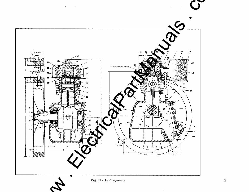
f PIPE AIR DISCHARGE
Fig. 13 - Air Compressor
1 1
•:''''�10
11
\� 48 'W' I 39
to:) <0
www . El
ectric
alPar
tMan
uals
. com

www . El
ectric
alPar
tMan
uals
. com
;II/){. � t{'6LA : PA"£5� -H- � ...,jf-- (
--. - - · � ' I
1/- POL.£ A V)( . sw.
M CP
-PS I I TB
liZ "i $r-�-c-��-- �-�l � s" \Z{)
7A � A5
TB�UA
HOGIS/H6 ('. v.)
3 1 . 3 2
I I �c
H -
www . El
ectric
alPar
tMan
uals
. com

www . El
ectric
alPar
tMan
uals
. com
\
www . El
ectric
alPar
tMan
uals
. com
www . El
ectric
alPar
tMan
uals
. com