integra 1630 low profile digital metering system · energy division integra 1630 low profile...
TRANSCRIPT
ENERGY DIVISION
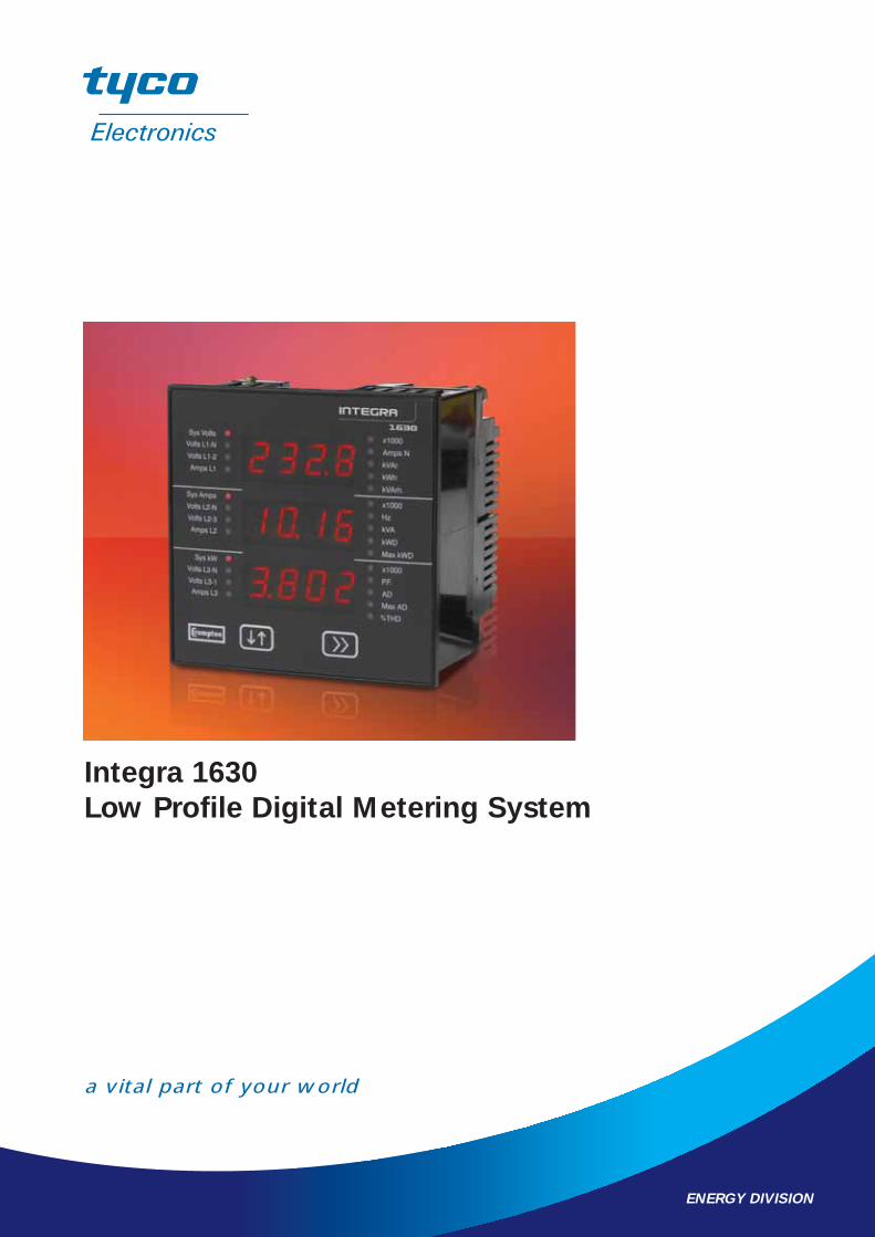
Integra 1630
Low Profile Digital Metering System
a vital part of your world
DIN Integra 1630 Series
OperationThe multifunction Integra 1630 digital metering system offers uncomplicated operationand high accuracy measurement of three-phase voltage, current, frequency, Watts, VAr,VA, energy, power factor, and total harmonic distortion measurement of both phaseand system, current and voltage.
3-phase 4-wire system line-to-line voltage measurements are often a vector calculationof the line-to-neutral voltage measurements. However, Integra 1630 digital meteringsystem includes true measurement of both line-to-neutral, and line-to-linemeasurements, ensuring accurate readings even with unusual wiring configurations(e.g. 4-wire open delta). To suit the requirements of individual power monitoringapplications, the Integra 1630 digital metering system offers simple programming anddisplay via the menu driven interface. Alternatively, an optional Windows-basedsoftware package can be used for remote configuration and monitoring. Onceconfigured by either method, simultaneous monitoring of up to 60 electrical and powerquality variables can be communicated to building management systems via pulsed ordigital communication options.
If customer requirements extend beyond the original specified capabilities, thefunctionality of this innovative product is easily enhanced to meet new clientexpectations. Integra plug-in option modules allow cost effective upgrades with anycombination of pulsed and digital communication outputs. The option module isinterchangeable without recalibration.
AccuracyIntegra 1630 digital metering systems utilise true rms measurement techniques up tothe 31st harmonic. An exceptional tolerance to high harmonic frequencies is achievedfrom a robust frequency detection method, which is able to detect the fundamentalfrequency on any phase. For safe maintenance, the system indicates CT current in theabsence of voltage signals.
System Input
Designed for all low, medium and high voltage switchgear and distribution systems, theIntegra 1560 and 1580 digital metering system offer programmable VT and CT ratiocapability. Direct connection up to 480V AC with 5A CT inputs is standard, and 1A CTinputs are optional.
FeaturesLow profileHigh contrast LED displayLED annunciators for each measuredparameter
User programmable system configuration(4-wire default)Fully programmable VT and CT ratiosCurrent demand per phaseElapsed time counter for connected loadsRemovable bezel for very low profileapplications
Benefits
True rms measurementHigh accuracy <0.2% on somemeasurementsConfigurable via software package ormenu-driven interfaceImport and export monitoring
Applications
Switchgear distribution systemsControl panelsEmbedded generationEnergy managementBuilding managementUtility power monitoringProcess controlMotor monitoring
Compliant
IEC1010-1 (BSEN 61010-1 – 2001)
1
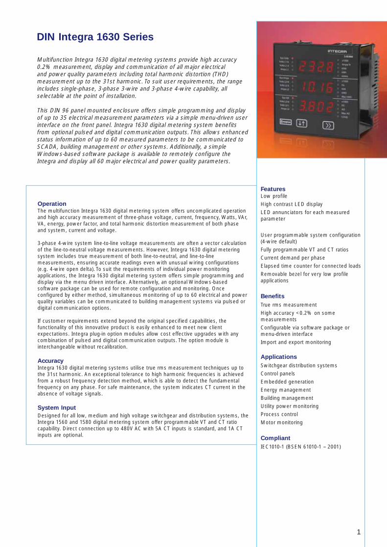
Multifunction Integra 1630 digital metering systems provide high accuracy0.2% measurement, display and communication of all major electrical and power quality parameters including total harmonic distortion (THD)measurement up to the 31st harmonic. To suit user requirements, the rangeincludes single-phase, 3-phase 3-wire and 3-phase 4-wire capability, allselectable at the point of installation.
This DIN 96 panel mounted enclosure offers simple programming and displayof up to 35 electrical measurement parameters via a simple menu-driven userinterface on the front panel. Integra 1630 digital metering system benefitsfrom optional pulsed and digital communication outputs. This allows enhancedstatus information of up to 60 measured parameters to be communicated toSCADA, building management or other systems. Additionally, a simpleWindows-based software package is available to remotely configure theIntegra and display all 60 major electrical and power quality parameters.
2
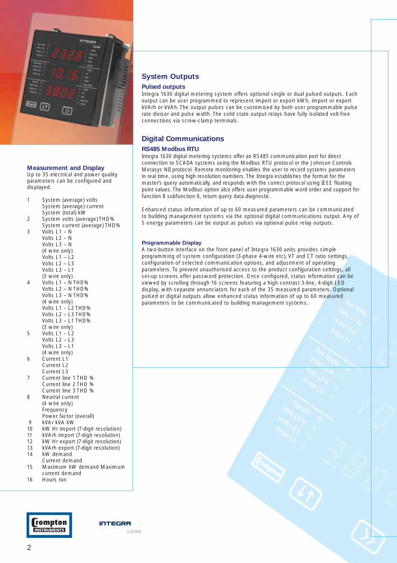
Measurement and DisplayUp to 35 electrical and power qualityparameters can be configured anddisplayed.
1 System (average) voltsSystem (average) currentSystem (total) kW
2 System volts (average) THD%System current (average) THD%
3 Volts L1 – NVolts L2 – NVolts L3 – N(4 wire only)Volts L1 – L2Volts L2 – L3Volts L3 – L1(3 wire only)
4 Volts L1 – N THD%Volts L2 – N THD%Volts L3 – N THD%(4 wire only) Volts L1 – L2 THD%Volts L2 – L3 THD%Volts L3 – L1 THD%(3 wire only)
5 Volts L1 – L2Volts L2 – L3Volts L3 – L1 (4 wire only)
6 Current L1Current L2Current L3
7 Current line 1 THD %Current line 2 THD %Current line 3 THD %
8 Neutral current(4 wire only)FrequencyPower factor (overall)
9 kVAr kVA kW 10 kW Hr import (7-digit resolution) 11 kVArh import (7-digit resolution) 12 kW Hr export (7-digit resolution) 13 kVArh export (7-digit resolution) 14 kW demand
Current demand15 Maximum kW demand Maximum
current demand16 Hours run
System Outputs
Pulsed outputsIntegra 1630 digital metering system offers optional single or dual pulsed outputs. Eachoutput can be user programmed to represent import or export kWh, import or exportkVArh or kVAh. The output pulses can be customised by both user programmable pulserate divisor and pulse width. The solid state output relays have fully isolated volt-freeconnections via screw-clamp terminals.
Digital Communications
RS485 Modbus RTUIntegra 1630 digital metering systems offer an RS485 communication port for directconnection to SCADA systems using the Modbus RTU protocol or the Johnson ControlsMetasys NII protocol. Remote monitoring enables the user to record systems parametersin real time, using high resolution numbers. The Integra establishes the format for themaster’s query automatically, and responds with the correct protocol using IEEE floatingpoint values. The Modbus option also offers user programmable word order and support forfunction 8 subfunction 0, return query data diagnostic.
Enhanced status information of up to 60 measured parameters can be communicatedto building management systems via the optional digital communications output. Any of5 energy parameters can be output as pulses via optional pulse relay outputs.
Programmable Display
A two-button interface on the front panel of Integra 1630 units provides simpleprogramming of system configuration (3-phase 4-wire etc), VT and CT ratio settings,configuration of selected communication options, and adjustment of operatingparameters. To prevent unauthorised access to the product configuration settings, allset-up screens offer password protection. Once configured, status information can beviewed by scrolling through 16 screens featuring a high contrast 3-line, 4-digit LEDdisplay, with separate annunciators for each of the 35 measured parameters. Optionalpulsed or digital outputs allow enhanced status information of up to 60 measuredparameters to be communicated to building management systems.
3
Outputs (optional)
RS485 communications: Two wire half duplex Baud rates: 4800, 9600, 19200, 38400Pulsed: Solid state relaysPulse duration: 60, 100 or 200 milliseconds Contact rating 50mA max at 250V AC max.Pulsed outputs: 1 or 2
Auxiliary
Standard nominal supply 100V – 250V AC or DC voltage: (85V – 287V AC absolute limits)
(85V – 312V DC absolute limits) AC supply frequency range: 45–66Hz AC supply burden: 6VA Optional auxiliary DC supply: 12V–48V DC
(10.2V–60V DC absolute limits) DC supply burden: 6VA
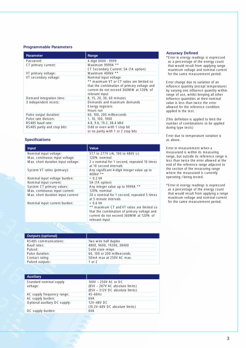
Parameter Range
Password: 4 digit 0000 - 9999 CT primary current: Maximum 9999A **
CT Secondary Current: 5A (1A option)VT primary voltage: Maximum 400kV **VT secondary voltage: Nominal input voltage
** maximum VT or CT ratios are limited so that the combination of primary voltage and current do not exceed 360MW at 120% of relevant input
Demand integration time: 8, 15, 20, 30, 60 minutes 3 independent resets: Demands and maximum demands
Energy registersHours run
Pulse output duration: 60, 100, 200 milliseconds Pulse rate divisors: 1, 10, 100, 1000 RS485 baud rate: 4.8, 9.6, 19.2, 38.4 kBd RS485 parity and stop bits: Odd or even with 1 stop bit
or no parity with 1 or 2 stop bits
Programmable Parameters
Input Value
Nominal input voltage: 57.7 to 277V L-N, 100 to 480V L-L Max. continuous input voltage: 120% nominal Max. short duration input voltage: 2 x nominal for 1 second, repeated 10 times
at 10 second intervalsSystem VT ratios (primary): Any significant 4-digit integer value up to
400kV **Nominal input voltage burden: < 0.2 VA Nominal input current: 5A (1A option) System CT primary values: Any integer value up to 9999A ** Max. continuous input current: 120% nominal Max. short duration input current: 20 x nominal for 1 second, repeated 5 times
at 5 minute intervalsNominal input current burden: < 0.6 VA
** maximum CT and VT ratios are limited sothat the combination of primary voltage andcurrent do not exceed 360MW at 120% of relevant input
Specifications
Accuracy Defined*Error in energy readings is expressedas a percentage of the energy countthat would result from applying rangemaximum voltage and nominal currentfor the same measurement period.
Error change due to variation of aninfluence quantity (except temperature)by varying one influence quantity withinrange of use, whilst keeping all otherinfluence quantities at their nominalvalue is less than twice the errorallowed for the reference conditionapplied in the test.
(This definition is applied to limit thenumber of combinations to be appliedduring type tests)
Error due to temperature variation is as above.
Error in measurement when ameasurand is within its measuringrange, but outside its reference range isless than twice the error allowed at theend of the reference range adjacent tothe section of the measuring rangewhere the measurand is currentlyoperating / being tested.
*Error in energy readings is expressedas a percentage of the energy countthat would result from applying a rangemaximum voltage and nominal currentfor the same measurement period.
4
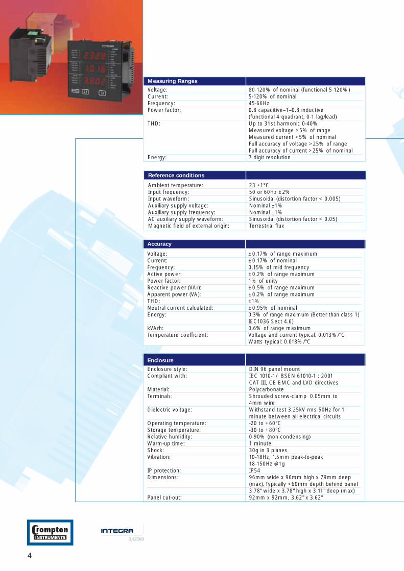
Enclosure
Enclosure style: DIN 96 panel mount Compliant with: IEC 1010-1/ BSEN 61010-1 : 2001
CAT III, CE EMC and LVD directives Material: Polycarbonate Terminals: Shrouded screw-clamp 0.05mm to
4mm wireDielectric voltage: Withstand test 3.25kV rms 50Hz for 1
minute between all electrical circuitsOperating temperature: -20 to +60°C Storage temperature: -30 to +80°C Relative humidity: 0-90% (non condensing) Warm-up time: 1 minute Shock: 30g in 3 planes Vibration: 10-18Hz, 1.5mm peak-to-peak
18-150Hz @1g IP protection: IP54 Dimensions: 96mm wide x 96mm high x 79mm deep
(max). Typically <60mm depth behind panel3.78" wide x 3.78" high x 3.11" deep (max)
Panel cut-out: 92mm x 92mm, 3.62" x 3.62"
Reference conditions
Ambient temperature: 23 ±1°C Input frequency: 50 or 60Hz ±2% Input waveform: Sinusoidal (distortion factor < 0.005) Auxiliary supply voltage: Nominal ±1% Auxiliary supply frequency: Nominal ±1% AC auxiliary supply waveform: Sinusoidal (distortion factor < 0.05) Magnetic field of external origin: Terrestrial flux
Accuracy
Voltage: ±0.17% of range maximum Current: ±0.17% of nominal Frequency: 0.15% of mid frequency Active power: ±0.2% of range maximum Power factor: 1% of unity Reactive power (VAr): ±0.5% of range maximum Apparent power (VA): ±0.2% of range maximum THD: ±1% Neutral current calculated: ±0.95% of nominal Energy: 0.3% of range maximum (Better than class 1)
IEC1036 Sect 4.6) kVArh: 0.6% of range maximum Temperature coefficient: Voltage and current typical: 0.013%/°C
Watts typical: 0.018%/°C
Measuring Ranges
Voltage: 80-120% of nominal (functional 5-120%) Current: 5-120% of nominal Frequency: 45-66Hz Power factor: 0.8 capacitive–1–0.8 inductive
(functional 4 quadrant, 0-1 lag/lead) THD: Up to 31st harmonic 0-40%
Measured voltage >5% of rangeMeasured current >5% of nominalFull accuracy of voltage >25% of range Full accuracy of current >25% of nominal
Energy: 7 digit resolution
5
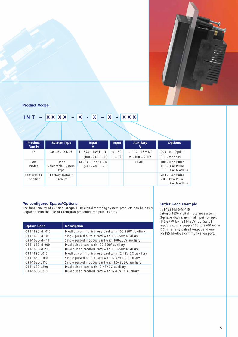
Option Code Description
OPT-1630-M- 010 Modbus communications card with 100-250V auxiliaryOPT-1630-M-100 Single pulsed output card with 100-250V auxiliaryOPT-1630-M-110 Single pulsed modbus card with 100-250V auxiliaryOPT-1630-M-200 Dual pulsed card with 100-250V auxiliaryOPT-1630-M-210 Dual pulsed modbus card with 100-250V auxiliaryOPT-1630-L-010 Modbus communications card with 12-48V DC auxiliaryOPT-1630-L-100 Single pulsed output card with 12-48V DC auxiliaryOPT-1630-L-110 Single pulsed modbus card with 12-48VDC auxiliaryOPT-1630-L-200 Dual pulsed card with 12-48VDC auxiliaryOPT-1630-L-210 Dual pulsed modbus card with 12-48VDC auxiliary
Pre-configured Spares/OptionsThe functionality of existing Integra 1630 digital metering system products can be easilyupgraded with the use of Crompton preconfigured plug-in cards.
Product Codes
Order Code Example
INT-1630-M-5-M-110 Integra 1630 digital metering system, 3-phase 4-wire, nominal input voltage,140-277V L-N (241-480V) L-L, 5A CTinput, auxiliary supply 100 to 250V AC orDC, one relay pulsed output and oneRS485 Modbus communication port.
I N T – X X X X – X - X – X - X X X
Product Codes
I N T – X X X X – X - X – X - X X X
Product System Type Input Input Auxiliary Options
Family V I V
16 30–LED DIN96 L - 57.7 - 139 L - N 5 – 5A L – 12 - 48 V DC 000 - No Option
(100 - 240 L - L) 1 – 1A M - 100 – 250V 010 - Modbus
Low User M - 140 - 277 L - N AC/DC 100 - One PulseProfile Selectable System (241 - 480 L - L) 110 - One Pulse
Type One Modbus
Features as Factory Default 200 - Two PulseSpecified - 4 Wire 210 - Two Pulse
One Modbus
6
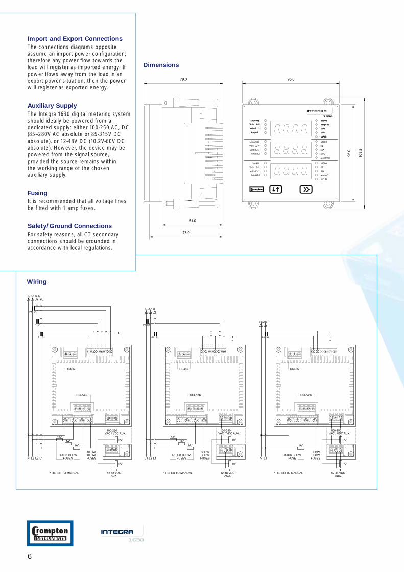
Dimensions
Import and Export Connections
The connections diagrams oppositeassume an import power configuration;therefore any power flow towards theload will register as imported energy. Ifpower flows away from the load in anexport power situation, then the powerwill register as exported energy.
Auxiliary Supply
The Integra 1630 digital metering systemshould ideally be powered from adedicated supply: either 100-250 AC, DC(85–280V AC absolute or 85-315V DCabsolute), or 12-48V DC (10.2V-60V DCabsolute). However, the device may bepowered from the signal source,provided the source remains within the working range of the chosenauxiliary supply.
Fusing
It is recommended that all voltage linesbe fitted with 1 amp fuses.
Safety/Ground Connections
For safety reasons, all CT secondaryconnections should be grounded inaccordance with local regulations.
Wiring
7
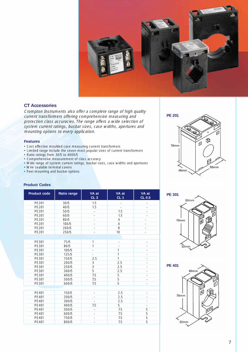
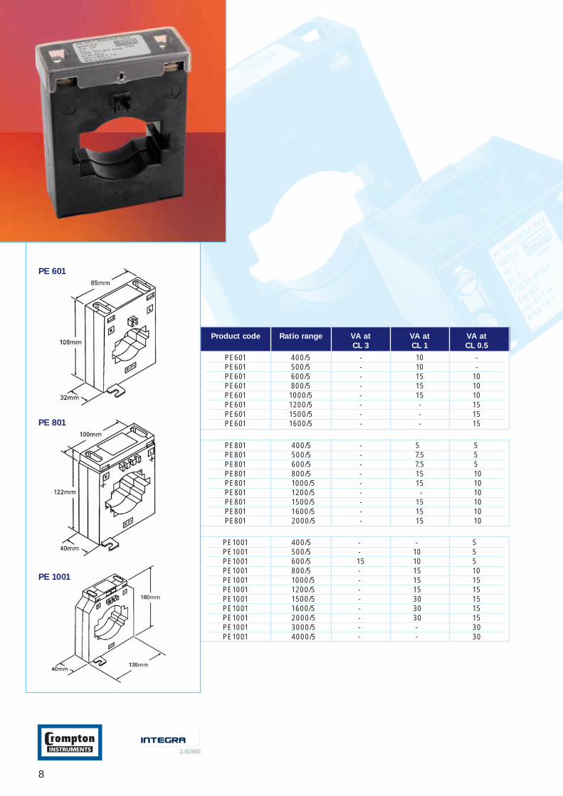
CT Accessories
Crompton Instruments also offer a complete range of high qualitycurrent transformers offering comprehensive measuring andprotection class accuracies. The range offers a wide selection ofsystem current ratings, busbar sizes, case widths, apertures andmounting options to every application.
Features
• Cost effective moulded case measuring current transformers• Limited range include the seven most popular sizes of current transformers• Ratio ratings from 30/5 to 4000/5• Comprehensive measurement of class accuracy• Wide range of system current ratings, busbar sizes, case widths and apertures • Wire sealable terminal covers• Feet mounting and busbar options
Product code Ratio range VA at VA at VA at
CL 3 CL 1 CL 0.5
PE201 30/5 1.5 - -PE201 40/5 1.5 - -PE201 50/5 - 1.5 -PE201 60/5 - 1.5 -PE201 80/5 - 4 -PE201 100/5 - 4 -PE201 200/5 - 8 -PE201 250/5 - 10 -
Product Codes
PE301 75/5 1 - -PE301 80/5 1 - -PE301 100/5 - 1 -PE301 125/5 - 1 -PE301 150/5 2.5 1 -PE301 200/5 3 2.5 -PE301 250/5 3 2.5 -PE301 300/5 5 2.5 -PE301 400/5 7.5 5 -PE301 500/5 7.5 5 -PE301 600/5 7.5 5 -
PE401 150/5 - 2.5 -PE401 200/5 - 2.5 -PE401 300/5 - 2.5 -PE401 400/5 7.5 5 -PE401 500/5 - 7.5 5PE401 600/5 - 7.5 5PE401 750/5 - 7.5 5PE401 800/5 - 7.5 5
PE 201
PE 301
PE 401
8
Product code Ratio range VA at VA at VA at
CL 3 CL 1 CL 0.5
PE601 400/5 - 10 -PE601 500/5 - 10 -PE601 600/5 - 15 10PE601 800/5 - 15 10PE601 1000/5 - 15 10PE601 1200/5 - - 15PE601 1500/5 - - 15PE601 1600/5 - - 15
PE801 400/5 - 5 5PE801 500/5 - 7.5 5PE801 600/5 - 7.5 5PE801 800/5 - 15 10PE801 1000/5 - 15 10PE801 1200/5 - - 10PE801 1500/5 - 15 10PE801 1600/5 - 15 10PE801 2000/5 - 15 10
PE1001 400/5 - - 5PE1001 500/5 - 10 5PE1001 600/5 15 10 5PE1001 800/5 - 15 10PE1001 1000/5 - 15 15PE1001 1200/5 - 15 15PE1001 1500/5 - 30 15PE1001 1600/5 - 30 15PE1001 2000/5 - 30 15PE1001 3000/5 - - 30PE1001 4000/5 - - 30
PE 601
PE 801
PE 1001

Tyco Electronics UK Limited, Crompton InstrumentsFreebournes Road, Witham, Essex, CM8 3AH, UKPhone: ++44 (0) 870 870 7500 Fax: ++44 (0) 870 240 5289
a vital part of your world
© Tyco Electronics CI-EPP-Integra1630-05/06
All of the above information, including drawings, illustrations and graphic design, reflects our present understanding and is to thebest of our knowledge and belief correct and reliable. Users, however, should independently evaluate the suitability of each productfor the desired application. Under no circumstances, does this constitute an assurance of any particular quality or performance. Suchan assurance is only provided in the context of our product specifications or explicit contractual arrangements. Our liability for theseproducts is set forth in our standard terms and conditions of sale. Tyco is a trademark. CROMPTON is a trademark of CromptonParkinson Ltd. and is used by Tyco Electronics under licence. Other trademarks or company names used herein are the property ofrespective owners.
Energy Division –economical solutions for the electrical power industry: cable accessories,connectors & fittings, electrical equipment, instruments, lighting controls, insulators &insulation enhancement and surge arresters.