integration of commercial mobile satellite services into
TRANSCRIPT


DUDLEY KNOX LIBRARYNAVAL POvSTGRaDUATE SCHOOLMONTEREY CA 93943-5101


NAVAL POSTGRADUATE SCHOOLMonterey, California
THESIS
INTEGRATION OF COMMERCIAL MOBH-E SATELLITESERVICES INTO NAVAL COMMUNICATIONS
by
Gary Reese Stone
September, 1997
Thesis Advisor:
Second Reader: Donald v
Brij Agrawal
Z. Wadsworth
Approved for public release; distribution is unlimited


REPORT DOCUMENTATION PAGE=-=
Form Approved
OMBNo. 0704-0188
Public reporting burden for this collection of information is estimated to average 1 hour per response, including the time for reviewing instruction, searching
existing data sources, gathering and maintaining the data needed, and completing and reviewing the collection of information. Send comments regarding
this burden estimate or any other aspect of this collection of information, including suggestions for reducing this burden, to Washington headquarters
Services, Directorate for Information Operations and Reports, 1 21 5 Jefferson Davis Highway, Suite 1204, Artington, VA 22202-4302, and to the Office of
Management and Budget, Papenwork Reduction Project (0704-0188) Washington DC 20503.
1. AGENCY USE ONLY (Leave blank) 2. REPORT DATESeptember 1997
3. REPORT TYPE AND DATES COVEREDMaster's Thesis
4. TITLE AND SUBTITLE Integration of Commercial Mobile Satellite Services into Naval
Communications
S. FUNDING NUMBERS
6. AUTHOR(S)
Stone, Cary Reese
7. PERFORMING ORGANIZATION NAME(S) AND ADDRESS(ES)
Naval Postgraduate School
Monterey, CA 93943-5000
8. PERFORMINGORGANIZATION REPORTNUMBER
9. SPONSORING / MONITORING AGENCY NAME(S) AND ADDRESS(ES) 10. SPONSORING/MONITORINGAGENCY REPORT NUMBER
11. SUPPLEMENTARY NOTES
The views expressed in this thesis are those of the author and do not reflect the ofificial policy or position of the Department of
Defense or the U.S. Government.
12a. DISTRIBUTION / AVAILABILITY STATEMENT
Approved for public release; distribution is unlimited.
12b. DISTRIBUTION CODE 11
ABSTRACT (maximum 200 words)
Mobile Satellite Services (MSS) need to be integrated into Naval Cominunications. DoD SATCOM military-
owned systems fall well short of meeting DoD SATCOM requirements in general and mobile SATCOM specifically.
This thesis examines DoD SATCOM requirements, especially those affecting communications on the move. From these
requirements, three systems ~ Inmarsat, Iridium and Globalstar ~ are identified and evaluated for potential use in Naval
Communications. An overview of space communications and each of the three systems is provided to identify general
operational capabilities, system strengths and system weaknesses. The Naval narrowband functional requirements
process is explored and DoD SATCOM and Commercial MSS ability to satisfy those requirements is assessed.
Potential Naval MSS communications missions are examined and possible DoD enhancements are considered for each
system as well as the impact these enhancements will have on each system. Recommendations are provided as to which
Naval communications missions are best suited for these enhanced MSS.14. SUBJECT TERMSMSS, PCS, Naval Narroband Functional Requirements, Space Communications, Inmarsat, Iridium,
Globalstar. DoD SATCOM, LEO, MEO, GEO
15. NUMBER OFPAGES
168
16. PRICE CODE
17. SECURITY CLASSIFICATION OFREPORTUnclassified
18. SECURITY CLASSIFICATION OFTHIS PAGEUnclassified
19. SECURITY CLASSIFI- CATIONOF ABSTFfACT
Unclassified
20. LIMITATIONOF ABSTRACT
UL
NSN 7540-01-280-5500
Form 298 (Rev. 2-89)
by ANSI Std. 239-18
Standard
Prescribed

u
Approved for public release; distribution is unlimited
INTEGRATION OF COMMERCIAL MOBILE SATELLITE SERVICESINTO NAVAL COMMUNICATIONS
Gary Reese Stone
Lieutenant, United States Navy
B.S., University of Mississippi, 1992
Submitted in partial fulfillment of the
requirements for the degree of
MASTER OF SCIENCE IN SPACE SYSTEMS OPERATIONS
from the
NAVAL POSTGRADUATE SCHOOLSeptember 1997

//^^//J
.#

DUDLEY KNOX LIBRARYNAVAL POSTGRADUATE SCHOOL
ABSTRACT MONTEREY CA 93943-6(ij(
Mobile Satellite Services (MSS) need "to be integrated into Naval
Communications. DoD SATCOM military-owned systems fall well short of
meeting DoD SATCOM requirements in general and mobile SATCOM
specifically. This thesis examines DoD SATCOM requirements, especially those
affecting communications on the move. From these requirements, three systems ~
Inmarsat, Iridium and Globalstar ~ are identified and evaluated for potential use in
Naval Communications. An overview of space communications and each of the
three systems is provided to identify general operational capabilities, system
strengths and system weaknesses. The Naval narrowband functional requirements
process is explored and DoD SATCOM and Commercial MSS ability to satisfy
those requirements is assessed. Potential Naval MSS communications missions are
examined and possible DoD enhancements are considered for each system as well
as the impact these enhancements will have on each system. Recommendations are
provided as to which Naval communications missions are best suited for these
enhanced MSS.

VI

TABLE OF CONTENTS
I. INTRODUCTION 1
A. BACKGROUND 1
B. PURPOSE 4
C. ORGANIZATION 4
1
.
Chapter II . Naval Narrowband Functional Requirements 4
2. Chapter III. Overview of Commercial Mobile Satellite Services .. 4
3. Chapter IV. Integration of Commercial Mobile Satellite Services
into Naval Communications Architecture 5
4 Chapter V. Conclusions and Recommendations 5
n. NAVAL NARROWBAND FUNCTIONAL REQUIREMENTS 7
A. NAVAL OPERATIONS 7
1. Forward ...From the Sea 7
2. Peacetime Forward Presence Operations 7
3. Naval Operations — Other than War 8
4. Sealift 9
5. Naval Operations in War 9
6. Joint Operations 10
B. DOD SATCOM FUNCTIONAL REQUIREMENTS DOCUMENT 11
1. Requirements Databases 11
2. Requirements Characteristics and Functional Areas 12
3. Operational Deployment Scenarios 14
a. Peacetime Scenario 15
vii

b. CombinedMajor Regional Conflict Scenario (CMRC) .... 1
5
c. Multiple Lesser Regional Conflict Scenario (MLRC) 16
4. Capacity Estimates 17
a. Composite Capacity 17
b. Highly Protected Capacity 18
c. Protected Capacity 19
d. Minimally Protected Capacity 20
e. Terminal Capacity 20
C. DOD SATCOM SYSTEM LIMITATIONS 21
1. Replenishment ofDoD-Owned Capability 22
2. Connectivity 23
3. Protection 24
4. Access and Control 24
5. Interoperability 25
6. Flexibility 25
7. Quality of Service 26
D. MOBILE USER STUDY REQUIREMENTS (MUS) WORKINGINTEGRATED PRODUCT TEAM (WIPT) 26
1. MUS WIPT Overview 27
2. MUS WIPT Requirements 27
3. MSS Satisfying MUS WIPT Requirements 28
E. SELECTION OF MSS FOR FURTHER STUDY 29
F. DOD UHF SYSTEMS VS MSS 30
viii

III. OVERVffiW OF COMMERCIAL MOBILE SATELLITE SERVICES 33
A. SPACE COMMUNICATIONS 33
1. Space Segment 33
2. Ground Segment 37
3. Multiple Access Methods 38
a. Frequency Division Multiple Access (FDMA) 39
h. Time Division Multiple Access (TDK4A) 40
c. Code Division Multiple Access (CDMA) 41
B. INMARSAT 43
1. System Overview 43
a. Space Segment 44
b. Ground Segment 47
2. System Strengths 51
3. System Weaknesses 54
C. IRIDIUM 56
1. System Overview 56
a. Space Segment 58
h Ground Segment 62
2. System Strengths 66
3. System Weaknesses 67
D. GLOBALSTAR 70
1. System Overview 70
IX

a. Space Segment 73
b. Ground Segment 77
2. System Strengths 83
3. System Weaknesses 86
IV. INTEGRATION OF COMMERCIAL MOBILE SATELLITE SERVICESINTO NAVAL COMMUNICATIONS 89
A. MSS POTENTIAL NAVAL COMMUNICATIONS MISSIONS 89
1. Polar Communications 90
2. VIP/Flag Communications 91
3. GBS Orderwire Communications 92
4. Combat Search and Rescue (CSAR) Communications 93
5. Command and Control (C2) of Tactical Forces Communications. 94
6. Maritime Operations Command Communications 95
7. Special Operations Communications 96
8. Naval Surface Fire Support (NSFS) Ship-to-Shore
Communications 97
9. Logistics Support Communications 98
10. Moral Support Communications 99
1 1
.
Peace Keeping and Humanitarian Operations Communications. . 1 00
12. Military Support to Civilian Authorities Communications 101
B. POTENTIAL DOD ENHANCEMENTS TO COMMERCIALMOBILE SATELLITE SERVICES 102
1. Inmarsat 102
2. Iridium 104

3. Globalstar 108
C. DOD UHF SYSTEMS AND DOD-ENHANCED MSS ABILITY TOSATISFY DOD/NAVAL REQUIREMENTS Ill
D. INTEGRATION OF INMARSAT INTO NAVALCOMMUNICATIONS 113
E. INTEGRATION OF IRIDIUM INTO NAVAL COMMUNICATIONS115
F. INTEGRATION OF GLOBALSTAR INTO NAVALCOMMUNICATIONS 119
V. CONCLUSIONS AND RECOMMENDATIONS 123
A. CONCLUSIONS 123
B. RECOMMENDATIONS 125
APPENDIX A UHF SATCOM'S ABILITY TO SATISFY MRC REQUIREMENTS127
APPENDIX B. ACRONYMS 131
APPENDIX C. GLOSSARY 135
LIST OF REFERENCES 139
INITIAL DISTRIBUTION LIST 143
XI

xu

LIST OF FIGURES
Figure 2-1. Current MILSATCOM Life Expectancy 22
Figure 3-L Typical GEO Satellite Coverage Area 34
Figure 3-2. Numerous LEO Coverage Areas within GEO Footprint 35
Figure 3-3. Frequency Division Multiple Access 40
Figure 3-4. Time Division Multiple Access 41
Figure 3-5. Code Division Multiple Access 42
Figure 3-6. FDMA, TDMA and CDMA in the Time-Frequency Plane 43
Figure 3-7. Inmarsat Satellite Coverage Areas 45
Figure 3-8. Inmarsat III Spot Beams 46
Figure 3-9. Inmarsat A and B Standard Configuration 49
Figure 3-10. Comsat Fiber Relay Network 53
Figure 3-11. Overview of Iridium System 58
Figure 3-12. Iridium Instantaneous Coverage Areas 59
Figure 3-13. Iridium Satellite Constellations 59
Figure 3-14. Iridium Satellite 60
Figure 3-15. Iridium Satellite Links 61
Figure 3-16. Iridium Handheld Phone and Pager 64
Figure 3-17. How Iridium Handles a Handset to PSTN Phone Call 65
Figure 3-18. Globalstar System Architecture 73
Figure 3-19. Globalstar Satellite Architecture 74
Figure 3-20. Globalstar's Satellite Orbital Paths 75
xiii

Figure 3-21. Globalstar's Satellite Coverage 76
Figure 3-22. Globalstar's Frequency Plan 77
Figure 3-23. Globalstar's Data Network 78
Figure 3-24. Artist Conception of a Globalstar Gateway 80
Figure 3-25. Globalstar's Personal Subscriber Units 81
Figure 3-26. Globalstar's Registration and Authentication Procedure 82
Figure 3-27. Globalstar's Billing Procedure 83
Figure 3-28. Globalstar's Path Diversity 85
Figure 4-1. Inmarsat Naval Communications Missions 115
Figure 4-2. Iridium Naval Communications Missions 119
Figure 4-3. Globalstar Naval Communications Missions 122
XIV

LIST OF TABLES
Table 1-1. Other Mobile Satellite Services Providers 3
Table 2-1. Operational Threats and Mitigation Techniques 14
Table 2-2. CMRC Force Structure 16
Table 2-3. MLRC Force Structure 16
Table 2-4. CMRC/MLRC Force Structure Comparison 16
Table 2-5. Narrowband Composite Capacity (2005-2010) 17
Table 2-6a. Narrowband Highly Protected Capacity (2005-20 10) 18
Table 2-6b. Highly Protected Capacity Break-out (2005-2010) 18
Table 2-7a. Narrowband Protected Capacity (2005-2010) 19
Table 2-7b. Protected Capacity Break-out (2005-2010) 19
Table 2-8. Narrowband Minimally Protected Capacity (2005-2010) 20
Table 2-9a. Narrowband (Netted) Capacity by Terminal (2005-2010) 21
Table 2-9b. Narrowband (Point to Point) Capacity by Terminal (2005-2010) 21
Table 2-10. DoD SATCOM UHF Unfulfilled Requirements 24
Table 2-11. Required Capabilities Voting Results 28
Table 2-12. MSS Ability to Satisfy Required Capabilities 28
Table 2-13. Reasons for MSS Exclusion 30
Table 2-14. Using MSS WIPT Requirements to compare DoD UHF Systems & MSS .31
Table 3-1. Satellite Subsystems 33
Table 3-2. Free Space Loss for a GEO and LEO Satellite 36
Table 3-3. Radio Frequency Bands Used for Satellite Communications 37
XV

Table 3-4. Ground Segment Terminals 38
Table 3-5. Access Method Advantages and Disadvantages 39
Table 3-6. Inmarsat III Characteristics 47
Table 3-7. Inmarsat A and B SES services 48
Table 3-8. Navy Requirements Satisfied by Inmarsat 54
Table 3-9. Inmarsat A and B Service Costs 55
Table 3-10. Iridium SatelHte Frequency Bands 62
Table 3-11. Example of Iridium Costs for Netted Communications 68
Table 3-12. Strategic Partners System Component Responsibilities 71
Table 3-13. Gateway Features 79
Table 3-14. Example of Globalstar Costs for Netted Communications 86
Table 4-1. MSS Mission Requirements Defined 90
Table 4-2. Polar Communications Mission Requirements 91
Table 4-3. VTP/Flag Communications Mission Requirements 92
Table 4-4. GBS Orderwire Communications Mission Requirements 93
Table 4-5. CSAR Communications Mission Requirements 94
Table 4-6. C2 Tactical Forces Communications Mission Requirements 95
Table 4-7. Maritime Operations Command Communications 96
Table 4-8. Special Operations Communications 97
Table 4-9. NSFS Ship-to-Shore Communications 95
Table 4-10. Logistics Support Communications 99
XVI

Table 4-11. Morale Support Communications 100
Table 4-12. Peace Keeping and Humanitarian Operations 101
Table 4-13. Military Support to Civilian Authorities 102
Table 4-14. Inmarsat versus DoD-enhanced Inmarsat 1 04
Table 4-15. Iridium versus DoD-enhanced Iridium 108
Table 4-16. Globalstar versus DoD-enhanced Globalstar Ill
Table 4-17. DoD UHF Systems versus DoD-enhanced MSS in satisfying DoD/Naval
Functional Requirements 113
xvii

XVIU

EXECUTIVE SUMMARY
Current DoD Satcom Systems cannot deliver sufficient UHF services to support
today's widely dispersed mobile forces information intensive needs. By utilizing existing
and soon-to-be-realized commercial MSS capabilities, information flow to the Navy's
highly mobile and dispersed forces can be greatly increased. Comparing Naval Space
Command's SATCOM Functional Requirements Document's requirements for a Naval
force operating in a one-MRC scenario to UFO's capacity, Iridium's capacity and
Globalstar' s capacity highlights the potential gains in overall UHF communications
capacity that can be gained by integrating commercial MSS. The figure below depicts the
orders of magnitude of additional, untapped, commercial MSS capacity that can go a long
way to satisfying existing as well unforeseen UHF communications requirements.
AMin -
3500-
3000 -
2500 -
2000 -
1500 -
1000 -
500-
n .
Hmi Required
UFO
D Iridium
n Globalstar
mull^^^B^^^^^^^^^^K
^^^^^^^^^^^^B
I^^HfJHilliii
Required UFO Iridium Globalstar
Naval One-MRC UHF Requirements Versus UFO, Iridium and Globalstar Capacities
The three commercial MSS which provide the greatest potential for integration
into Naval communications are Inmarsat, Iridium and Globalstar. Inmarsat is already
XIX

integrated into half the fleet with the remaining half to have Inmarsat capability by the end
of FY 97 and can provide Naval ships with up to 64 kbps communications connectivity.
Iridium will be the first to market to provide cellular phone Uke satellite service and the
only MSS to provide crosslinks between its satellites giving it truly world-wide
communications capabilities. Globalstar will soon follow Iridium to market and has
advantages in its use of CDMA technologies which will provide greater signal security as
well as better operating characteristics in a tactical environment.
DoD enhancements will be necessary to increase the utility of integrating these
three commercial MSS into Naval communications. DoD enhancements will take the
form of contractual and technical techniques. These enhancements are necessary to satisfy
requirements which are unique to military communications such as assured access and
secure communications. Possible DoD enhancements for Inmarsat, Iridium and Globalstar
are summarized in the table below.
XX

MSS Potential DoD Enhancements
Inmarsat • STU III and KG-84 - secure communications.
• Contracting a lease for transponders - increase assured access.
Iridium • DoD gateway - increases call security, potential for netted service and
improves assured access among DoD users.
• Condor an NSA developed STU III device - secure communications.
• Integration of GPS and Microburst technology - CSAR missions and
remote sensor reporting.
• Use of highly directional antenna - strategic and polar operations.
• Contracting - priority preference, guaranteed call access and a surge
provision - increase assured access.
Globalstar • Combination of fixed and transportable DoD Gateway - increases call
security and assured access among DoD users.
• Condor an NSA developed STU III device - secure communications.
• Integration ofGPS and Microburst technology - CSAR missions and
remote sensor reporting.
• Group Services - enable broadcast and networking capabilities.
• Contracting - priority preference, guaranteed call access and a surge
provision - increase assured access.
Each of the DoD-enhanced MSS under discussion provide certain characteristics
which make them attractive for certain missions with some mission overlap. DoD-
enhanced Inmarsat provides Naval forces afloat with a larger two-way data rate capability
which can be used for bandwidth-intensive functions such as BDA, GCCS, and
Tomahawk MDU. Additionally, Inmarsat can support multiple, lower-data-rate services
such as SALTS, multiple secure phone sessions and morale and welfare services. DoD-
enhanced Iridium with its crosslinks and single DoD gateway is well-suited for missions
which require world-wide connectivity. World-wide missions which could be undertaken
by Iridium include certain VIP/Flag Travel, Logistic, CSAR, Polar,
Peacekeeping/Humanitarian, and Military Support to Civilian Agencies communications.
DoD-enhanced Globalstar with its CDMA technology, deployable DoD gateway and
XXI

Group Services can provide tactical mobile communications services in-theater. In-theater
missions for which DoD-enhanced Globalstar is well-suited include GBS Orderwire,
Logistics Support, C2 of Tactical Forces, Special Operations, and NSFS Ship-to-Shore
communications. The figure below summarizes the areas that best suit these DoD-
enhanced MSS.
DoD Enhanced
Inmarsat
' Maritime C2GCCS
' GBS Orderwire
' Secure Voice
' Tomahawk MDU' PSTN Access
' MWR, SALTS
DoD Enhanced
Iridium
' CSAR Operations
' VIP/Flag Travel
' Polar Operations
' Anti-Drug Operations
' Logistics Tracking
' Peacekeeping/Humanitarian Missions
• Military Support to Civilian Agencies
DoD Enhanced
Globalstar
' C2 of Tactical Forces
' Special Operations
' Naval Surface Fu-e Support
' GBS Orderwire
' Logistics Support
' Tactical Netted Services
' Unit ID and Tracking Capabilities
By capitalizing on each of the DoD-enhanced MSS strengths, DoD-enhanced MSS
communications can provide the missing mobile communications piece in the Naval
communications puzzle. In the long run, whether or not the Navy chooses to actively
integrate commercial MSS into its communications infrastructure, the Navy needs to
understand the implications of adversaries who will utilize commercial MSS.
xxii

ACKNOWLEDGMENT
The author would like to acknowledge the financial, academic and morale support
provided to him throughout the thesis process. The financial support of Naval Space
Command, Code N52, which allowed for travel to collect information vital to the
development of this thesis. The academic guidance and assistance of Professor Agrawal
and Professor Wadsworth in developing the final product. The morale support of my wife
Nora and my daughter Kara which enabled me to complete my thesis on time.
xxiu


I. INTRODUCTION
A. BACKGROUND
The Navy has made extensive use of commercial communications satellites since
commercial satellite services first became available. Since the early seventies, the Navy
has leased the services of commercial communications satellite systems such as Leasat to
provide narrowband UHF communications capability to its widely dispersed forces
worldwide. Even though numerous military communications satellites have been deployed
since that time, there still exists a great gulf between the Navy's demand for narrowband
satellite communications and the ability of Department of Defense (DoD) owned systems
to meet that demand. Being a global force operating on all the Earth's major oceans and
with information dominance becoming increasingly important, the Navy needs to expand
its ability for two-way global narrowband communications. Commercial narrowband
satellites can help provide that capability.
Narrowband communication is defined as low data rate communications providing
voice and data communications of less than 64 kbps. Those narrowband commercial
satellite communications systems operating in the UHF portion of the electromagnetic
spectrum allow for the use of smaller user terminals. These smaller terminals vary from
very small aperture terminals (VSAT) for geostationary (GEO) satellites and small
handheld omnidirectional antennae for low earth orbiting (LEO) satellites. The
narrowband commercial satellites providing these types of services are referred to as
Mobile Satellite Services/Systems (MSS). The small size and portability ofMSS terminals

are ideal for providing narrowband communications worldwide to the Navy who has
hundreds of diverse platforms of varying size spread across the globe. The ability of two
way Narrowband communications with any Navy platform anywhere in the world would
greatly enhance the Navy's ability to coordinate between widely dispersed forces, pass
time critical data, decrease response time to the National Command Authority's needs and
increase situational awareness throughout the Navy's global forces.
Every other day it seems as if another company is entering the MSS market.
Inmarsat, for one, has been providing ocean going vessels MSS for 10 to 15 years and
currently, provides virtually the entire Navy with ship fixed Inmarsat terminals capable of
up to 56 kbps MSS. Newly proposed MSS are focusing on the personal communication
services (PCS) portion of the market that provides a mobile individual user voice and data
service of up to 9.6 kbps. Iridium and Globalstar are two such satellite systems that
promise to provide worldwide or virtually worldwide hand held PCS. There are other
proposed MSS (summarized in Table 1-1) , however, industry and DoD analysts have
found Iridium and Globalstar to be the two MSS providers which will have the largest
impact on the PCS market in the near term. Inmarsat, Iridium and Globalstar are or will
soon be available for Naval use and their impact on the Navy's communications
architecture must be analyzed.

Parameter Skycell ICO Ellipso Odyssey
Primary Owner AMSC (Hughes
Communications)
ICO Global
Communications
Mobile
Communications
Holdings
TRW
Orbit Type GEO MEG MEG MEGOrbit Shape(s) Synchronous Circular Circular &
Elliptic
Circular
Orbit Alt (circular) km 35,786 10,400 8,068 10,355
Orbit Alt (ellipse) km N/A N/A Apogee - 7,486
Perigee - 5,000
N/A
Orbit Planes (number) 1 2 3 3
Inclination($) deg 0-1 45 1 @ 0° & 2 @116.6°
50
No of Sats (with spares) 2 12 17 14
Min Elev Angle (N.
Lat)
10 20 25 20
Primary Coverage Lats US & Parts S/A 70°N-55°S 70°N-47°S 70°N-55°S
Primary Coverage
Longs
US & Parts S/A All (Gaps over
far northern
latitudes and over
ocean)
All (Gaps over
far northern
latitudes and over
ocean)
All (Gaps over
far northern
latimdes and
over ocean)
Unique Design GEO Cellular Complex
anteima, onboard
processing
Travels through
Van Allen Belts/
New Solar Arrays
Satellite tracks
earth service
areas
Modulation/Handset TDMA TDMA CDMA CDMAAntenna
Beams/Satellite
23 121 37&61 61
Capacity, Hand-Held 6300 4500 2043 3000
Freq Band, Sat to User 1500-1600 MHz 2200 MHz 2483-2500 MHz 2483-2500
Freq Band, User to Sat 1500-1600 MHz 2000 MHz 1610-1626 MHz 1610-1626
Service Date IOC 1995 4Q 1999 3Q 1998 3Q 2000
Service Date FOC 1998 3Q 2000 2Q 1999 2Q2001
No. Earth Stations 1 > 12 >20 >7
Space Segment Cost
$M674 2600 (including
earth stations)
900 3200 (including
earth stations)
User Data Rates (kbps) 9.6 2.4, 4.8 0.3-9.6 2.4, 4.8, 9.6
Standard Handset
Costs
500-700 1000 1000 500-700
Usage cost, $ per
minute
0.50 1-2 0.20-0.40 1-2
Table 1-1. Other Mobile Satellite Services Providers. After Ref.[l].

B. PURPOSE
The Navy's narrowband functional requirements are examined to identify what, if
any, Naval narrowband requirements can be best satisfied using which MSS. The MSS
under consideration are Inmarsat, Iridium and Globalstar. Each system is described,
strengths assessed, weaknesses identified and DoD enhancements considered. An analysis
of the integration of these three MSS into the Naval Communications Architecture is
performed.
C. ORGANIZATION
1. Chapter II. Naval Narrowband Functional Requirements
The Navy's future narrowband functional requirements are summarized based on
Naval Operations, including material drawn from the DoD SATCOM Functional
Requirements Document and DoD SATCOM system limitations and the Mobile User
Study Requirements Working Integrated Product Team.
2. Chapter HI. Overview of Commercial Mobile Satellite Services
An overall examination of space communications is provided with three
commercial MSS providers being examined in detail ~ Inmarsat, Iridium and Globalstar.
In addition to an overview of each system, the strengths and weaknesses of each MSS are
evaluated in terms of satisfying the Navy's narrowband communications needs.

3. Chapter FV. Integration of Commercial Mobile Satellite Services into
Naval Communications
Potential methods for integrating Inmarsat, Iridium and Globalstar into the Navy's
communications architecture are examined. A review of potential Naval communications
missions and proposed DoD enhancements to these three MSS is included.
4. Chapter V. Conclusions and Recommendations
The relative advantages and disadvantages of a Naval communications architecture
based on DoD-owned MSS versus DoD-enhanced MSS are presented based on the
examination of three commercial MSS. Recommendations concerning future research
areas are provided.


n. NAVAL NARROWBAND FUNCTIONAL REQUIREMENTS
Naval Narrowband Functional Requirements (NNFR) have been developed by
examining Naval Operations, DoD SATCOM Functional Requirements Document,
examining DoD SATCOM system limitations and committee meetings such as the Mobile
User Study Requirements Working Integrated Product Team. The requirements process is
a cyclical process. There is no true beginning or end. What is produced after each
iteration, is a snapshot in time. The MILSATCOM requirements generated is used for
planning and implementation of next generation military satellite communications system
which will best be able to satisfy those requirements within physical and fiscal constraints.
A. NAVAL OPERATIONS
1. Forward ...From the Sea
Forward ...From the Sea is a strategic concept adopted by the Navy and Marine
Corps September 1992. ...From the Sea is a ftindamental shift from the blue water, open
ocean, large naval engagement strategy to a brown water, littoral regions which provides
support for land based joint operations. Although the strategy has changed, the purpose
of the Navy remains to project the United States' power and influence across the seas to
foreign waters and shores in both peace and war. [Ref 2; pp. 1-3]
2. Peacetime Forward Presence Operations
Naval Forces operate forward in peacetime to promote national influence, maintain
access to critical areas, provide stability, deter aggression and provide an initial crisis-

response capability. Forward deployed naval forces alone are a tangible symbol of U.S.
political commitments and military strength. They also promote peace through overseas
engagements and partnership with U.S. allies which increases regional stability and
decreases the need to fight in defense of our vital interests. Crisis response is the
emergent and timely dispatch of naval forces to a specific area to render assistance or
exert military force. Naval forces' forward deployment is essential to permit the United
States to act quickly in meeting any crises that may affect our security. [Ref 3: pp. 20]
3. Naval Operations — Other than War
As part of crisis response, Naval Operations ~ Other than War may require naval
forces to conduct such contingency activities as show of force, fi^eedom-of-navigation
operations, short duration combat intervention operations and post-combat security
restoration operations. The National Command Authority directs naval forces to protect
the United States' international right to perform the following duties:
Conduct contingency operations.
Evacuate noncombatant personnel.
Combat terrorism.
Aid host nations through security assistance and foreign internal
defense.
Assist other nations in defending themselves.
Enforce United Nations' economic sanctions.
Participate in peace-support operations.
Intercept vessels to prevent uncontrolled immigration.
Plan and conduct disaster relief, humanitarian assistance, and civil
support operations.
Coordinate public health operations.
Assist interagency counterdrug operations.

These activities maintain a visible and credible capability to fight and exercises many of the
wartime capabilities which may be needed to defend our nation in time of war. [Ref 3: pp.
21-23]
4. Sealift
Sealift is pivotal to supporting any large-scale deployment, reinforcement, and
resupply. Historically, sealift has accounted for 90-95% of the total cargo delivered
during military operations overseas. In order to provide this type of support, strategic
sealift employs ships in three broad categories:
• Prepositioning - This capability allows the U.S. to place sustainment
supplies near crisis areas for delivery to contingency forces.
• Surge - the initial deployment of U.S. based equipment and supplies in
support of a contingency, transported in rapid-reinforcement shipping.
• Sustainment - Shipping that transports resupply cargoes to build up
theater reserve stock levels.
Protecting logistical lines has always been a major factor in any successfiil campaign.
Sealift provides the U.S. with a logistical edge in any overseas operation. [Ref 3; pp. 24]
5. Naval Operations in War
The Navy's fiindamental role is sea control. Sea control protects naval forces'
ability to project power ashore by controlling the entire battlespace: subsurface, surface,
and airspace, both in the open ocean and littoral regions of the world. Sea control allows
the U.S. to:
• Protect sea lines of communications.
• Deny the enemy commercial and military use of the seas.
• Establish an area of operations for power projection ashore and support
of amphibious operations.
• Protect naval logistic support to forward deployed battle forces.

Control of the sea is accomplished through the following operations:
• Destroying or neutralizing enemy ships, submarines, aircraft, or mines.
• Disabling or disrupting enemy command and control.
• Destroying or neutralizing the land-based infrastructure that supports
enemy sea control forces.
• Seizing islands, choke points, peninsulas, and coastal bases along the
littorals.
• Conducting barrier operations in choke points that prevent enemy
mobility under, on, and above the sea.
Control of the sea does not imply absolute control over all areas of the sea. Rather,
complete sea control is only required of specific regions for particular periods of time, to
allow unencumbered naval operations. [Ref 3: pp. 26]
6. Joint Operations
Throughout the 20th century, naval forces have been operating in concert with the
Army and Air Force with great success. Coherent joint doctrine has been and is continuing
to be developed as a catalyst in developing ever increasing joint capabilities. Joint training,
education and experience is being developed during frequent joint operations and
exercises. A cornerstone to future joint operations is the development ofjoint C4I systems
which have the following characteristics:
• Interoperable - must possess the interoperability necessary to ensure
success in a joint and combined operations environment.
• Flexible - ability to meet changing situations and diversified operations
with a minimum of disruption or delay.
• Responsive - system must be reliable, redundant and timely.
• Mobile - systems must be as mobile as the forces they support.
• Disciplined - ensure that limited system resources are used to the best
advantage.
• Survivable - systems should be as survivable as the survival potential of
the associated command centers and weapon systems.
10

• Sustainable - economical design and employment of C4 systems
without sacrificing operational capability or survivability.
The future promises even greater integration between the services allowing the services to
further complement each others' unique capabilities in time of conflict. [Ref 4: pp. 5-9]
B. DOD SATCOM FUNCTIONAL REQUIREMENTS DOCUMENT
The Department of Defense (DoD) has a continuing need to utilize satellite
communications (SATCOM) to provide for its information transfer needs in a global
threat environment. The Defense Information Systems Agency (DISA) developed the
DoD's SATCOM Functional Requirements Document (DSFRD) in 1996 to describe a
user's needs for satellite communications service in the post-2005 time frame. The
technical approach was to derive requirements from two separate databases, the
Integrated Communications Data Base (ICDB) and the Emerging Requirements Data
Base (ERDB) within the context of three operational scenarios: peacetime, multiple lesser
regional conflict (MLRC), and combined major regional conflict (CMRC). The DSFRD
intended use was for planning and study purposes.
1. Requirements Databases
The ICDB is a comprehensive data base of present day communications
requirements for DoD and selected non-DoD Government agencies maintained by DISA.
Contains terrestrial and commercial SATCOM data. Military SATCOM requirements are
submitted by the CINCs/Agencies and are validated by the Joint Staff. The ERDB
contains far-term requirements data not addressed by the ICDB. Additional factors
contributing to the ERDB are force structure changes, new technologies, weapons
11

systems information and doctrinal changes. Emerging requirements are submitted to
DISA and approved by the Joint Staff for planning and analysis purposes. The ERDB is
completely compatible with the ICDB. [Ref 5: pp. 1.2-1.3]
2. Requirements Characteristics and Functional Areas
Requirements characteristics apply in varying degrees to different classes of users
and missions and across five functional areas. The requirements are unconstrained and
independent of architectural solutions. The mobile and deployed warfighter's information
transfer needs are the focus of the following requirements characteristics:
• Connectivity - The geographical coverage of the satellite
communications system in reference to the users of that system and the
capacity of the system relative to data throughput.
• Protection - The ability to avoid, prevent, negate, or mitigate the
degradation, disruption, denial, unauthorized access, or exploitation of
communications services by adversaries or the environment.
• Access and control - Access means immediate accessibility and
availability when needed. Control refers to the ability to effectively
plan, operate, manage and manipulate the available SATCOMresources.
• Interoperablity- The ability of varying forces to communicate with
one another quickly and effectively.
• Flexibility - The ability to support the full dynamic range of military
operations and missions.
• Quality of Service - The ability to transfer information in a timely and
accurate manner.
These requirements characteristics have been mapped into five functional areas to describe
DoD SATCOM needs in various operational deployment scenarios. [Ref 5: pp. 2.1-2.26]
Functional areas describe the type of SATCOM services available to the user
community and the employment of SATCOM resources in supporting those services. The
five functional areas are:
12
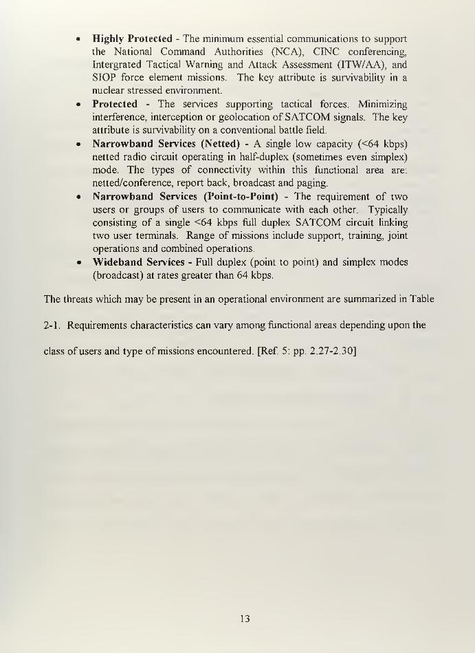
• Highly Protected - The minimum essential communications to support
the National Command Authorities (NCA), CINC conferencing,
Intergrated Tactical Warning and Attack Assessment (ITW/AA), and
SIOP force element missions. The key attribute is survivability in a
nuclear stressed environment.
• Protected - The services supporting tactical forces. Minimizing
interference, interception or geolocation of SATCOM signals. The key
attribute is survivability on a conventional battle field.
• Narrowband Services (Netted) - A single low capacity (<64 kbps)
netted radio circuit operating in half-duplex (sometimes even simplex)
mode. The types of connectivity within this functional area are:
netted/conference, report back, broadcast and paging.
• Narrowband Services (Point-to-Point) - The requirement of two
users or groups of users to communicate with each other. Typically
consisting of a single <64 kbps full duplex SATCOM circuit linking
two user terminals. Range of missions include support, training, joint
operations and combined operations.
• Wideband Services - Full duplex (point to point) and simplex modes
(broadcast) at rates greater than 64 kbps.
The threats which may be present in an operational environment are summarized in Table
2-1 . Requirements characteristics can vary among functional areas depending upon the
class of users and type of missions encountered. [Ref 5: pp. 2.27-2.30]
13

Operational Threat Mitigation Technique
High Altitude Electromagnetic Pulse (HEMP)A sudden very large surge of current produced by
a nuclear detonation at high altitude.
HEMPThe hardening and shielding of
electronics to mitigate EMP effects.
Scintillation
The collection of effects on the propagation
medium caused by nuclear detonations.
Anti-Scintillation (AS)
Techniques used to minimize effects
of scintillation
SIGEVTThe intercept and the collection signals
intelligence.
Low Probability of Intercept (LPI)
The protection from intercept and the
collection signals intelligence.
Detecting and Direction Finding
Detecting a signal and following its direction back
to its source.
Low Probability of Detection
(LPD)
The ability to transmit a
communications signal while denying
its detection and source location to
maintain covertness of operations.
JammingThe deliberate interference with electromagnetic
energy for the purpose of preventing or reducing
someone else's use of the electromagnetic
spectrum.
Anti-Jam (AJ)
Using methods and techniques to
decrease the likelihood of
communications disruption due to
jamming.
Table 2-1. Operational Threats and Mitigation Techniques. From Ref [5].
3. Operational Deployment Scenarios
DoD SATCOM requirements were presented in the context of three operational
scenarios: Peacetime, CMRC, and MLRC. These scenarios provided the framework used
to evaluate fiiture DoD SATCOM system capabilities in an operational setting. Because it
was impossible to predict where future conflicts would occur, the scenarios are
independent of geographic regions and the size of the theater of operations vary from
14

250,000 square miles for the smallest MLRC scenario and to 5,000,000 for the largest
CMRC scenario. [Ref 5: pp. 3.1]
a. Peacetime Scenario
Normal day-to-day operations fall into this category. U.S. Forces are not
engaged in any crisis operations or conflict. The majority of these requirements represent
the background SATCOM requirements necessary in the more stressful warfighting
environments. Strategic forces deployed worldwide, VIP travel, forward deployed forces,
afloat forces performing global operations, joint operations, combined operations and
training all fall into the Peacetime Scenarios category. [Ref 5: pp. 3. 1-3.2]
b. Combined Major Regional Conflict Scenario (CMRC)
The CMRC Scenario represents the use of a large force in two
geographically separate regions. In this worst-case scenario, the U.S. and her allies are
engaged in near-simultaneous major regional conflicts (MRCs). Table 2-2 shows the
distribution of forces for each Areas of Responsibility (AOR) used for the CMRC
Scenario. Concentration of significant forces in two limited geographical areas could
potentially place a severe strain on the ability of the DoD SATCOM systems to adequately
satisfy DoD needs in a CMRC environment. This problem would be exacerbated if forces
in each AOR are competing for satellite resources within the same satellite region. [Ref 5:
pp. 31-3.4]
15

Region\.Battle
GroupReady
GroupCorps Division Expeditionary
Force
''*''Flpter''''^
WingEquivalent
Theater 1 5 2 2 7 1+ 7
Theater 2 4 1 1 3 1 9
Total 9 3 3 10 2+ 16
Table 2-2. CMRC Force Structure. From Ref. [5].
c Multiple Lesser Regional Conflict Scenario (MLRC)
MLRC involves use of medium size forces into a localized area in support
of U.S. interests. The MLRC scenario analyzes DoD SATCOM architecture options in
accommodating the needs of dispersed users in a combat environment. To develop this
scenario, forces where dispersed to four regions to support various operations including
peacekeeping, humanitarian and conflict missions. Two of the regions utilize sizable
forces under operational command of a CfNC and two regions use smaller forces under
the command of a Commander, Joint Task Force. Table 2-3 shows the apportionment of
MLRC forces and Table 2-4 Compares CMRS and MLRC force structures. [Ref 5: pp.
3.4-3.5]
Region^N.
'Carrieir""''
Battle
Group
i^^LmpKibiMisi
Ready
GroupCorps Division Expeditionary
Force
'"''''fipter'"'"
WingEquivalent
Theater 1 2* 1 1 2 1 4
Theater! 2* 1 3 1 4
Theater 3 2* 1 1 2
Theater 4 1 1 1 0.5 1
Total 7 3 2 7 2+ 11
* One CVGB in the AOR with the second in transit.
Table 2-3. MLRC Force Structure. From Ref [5].
16

"'~"~*"*"-'~-—__^^^^ Scenario
Unit ^"^""^"^^------^CMRC MLRC
Army Corps 3 2
Army Division 10 7
Carrier Battle Group 9 7
Amphibious Ready Group 3 3
Marine Expeditionary Force 2+ 2+
Fighter Wing equivalent 16 11
Table 2-4. CMRC/MLRC Force Stmcture Comparison. From Ref. [5].
4. Capacity Estimates
Using data from the requirements databases and the operational scenarios
described above, an analysis was made and tables created to reflect each operational
scenarios' capacity by composite, highly protected, protected, minimally protected and by
terminal categories.
a. Composite Capacity
Table 2-5 presents the minimum estimated narrowband SATCOM
throughput requirements in the 2005-1010 time frame for each of the three scenarios
discussed earlier. [Ref 6: pp. 4.9 - 4.10]
^"^^^ Scenario
Circuit Type ^^\^
Peacetime CMRC;.,:^^^,..;;,,. ,:,
.MLi^c
Mbps Circuits Mb^s Circuits Mbps Circuits
Narrowband (Netted) 2.5 900 6.5 1500 7.0 1500
Narrowband (Point to
Point)
115 2550 125 3200 135 3600
Total Narrowband 117.5 3450 131.5 4700 142 5100
Note: For netted service. 'circuits" column eqiials num 3er of "netv/orks"
Table 2-5. Narrowband Composite Capacity (2005-2010). After Ref [6].
17

b. Highly Protected Capacity
The United States nuclear forces, ITW/AA and the NCA all require global
high level of protection capable of operating in a nuclear trans- and post-attack
environment. Table 2-6a describes the highly protected narrowband capacity requirements
and Table 2-6b breaks those requirements into requisite protection mitigation measures.
[Ref 6:pp. 4.11 -4.12]
^^\^ Scenario
Circuit Type ^^--v^
Peacetime CMRC MLRC
Mbps Circuits Mbps Circuits Mbps Circuits
Narrowband (Netted) 0.4 165 2.0 210 2.0 210
Narrowband (Point to
Point)
1.6 115 1.6 130 1.6 130
Total Narrowband 2 280 3.6 340 3.6 340
Note: For netted service,
'
'circuits" column eqilals num ber of "networks".
Table 2-6a. Narrowband Highly Protected Capacity (2005-2010). After Ref [6].
""^'">-^,.^^^ Scenario
Mitigation Technique^
Peacetime CMRC MLRC
Mbps Circuits Mbps Circuits Mbps Circuits
Anti-Jam 20 300 20 350 20 350
Anti-scintillation 22 300 22 350 22 350
HEMP 16 250 16 280 16 280
LP! 4.5 40 5 50 4.0 35
LPD 5 40 5 50 4.0 35
Note: Includes wideband and most circuits require a combination of these features.
Table 2-6b. Highly Protected Capacity Break-out (2005-2010). After Ref [6].
18

c. Protected Capacity
The United States needs a robust anti-jam, LPI, and LPD protection for
many in-theater tactical forces to include maritime and amphibious battle group. These
forces operate in close proximity to hostile forces and must be able to protect their most
critical SATCOM links. Table 2-7a provides the narrowband protected capacity and
Table 2-7b breaks the protected capacity into its constituent parts. [Ref 6: pp. 4.12 -
4.13]
^^\^^ Scenario
Circuit Type ^'"^^
Peacetime CMRC MLRC
Mbps Circuits Mbps Circuits Mbps Circuits
Narrowband (Netted) 1.0 440 3.0 780 3.0 800
Narrowband (Point to
Point)
12 420 13 480 24 700
Total Narrowband 13 860 16 1260 27 1500
Note: For netted service,
'
'circuits" column eqilals numi3er of "netv/orks".
Table 2-7a. Narrowband Protected Capacity (2005-2010). After Ref [6].
y^^ Sc:enario
Mitigation Technique^
Peacetime CMRC ,,:.,,,,: MLRC
Mbps Circuits Mbps Circuits Mbps Circuits
Anti-Jam 600 1300 1346 2150 1600 2500
im 25 330 300 700 250 750
iXPD,.,.,,:V.,_^^^^^^^^^^ 40 330 300 700 250 750
Note: Includes wideband and most circuits requiring LPI/LPD also require AJ.
Table 2-7b. Protected Capacity Break-out (2005-2010). After Ref [6].
19

d. Minimally Protected Capacity
The minimal protected group of SATCOM are those communications that
do not require any AJ/LPI/LPD capabilities. This category satisfies a subset of the users
whose requirements who are separately covered in highly survivable and protected service
categories who may also desire to operate in a non-protected mode until the mission or
threat dictate otherwise. Logistics and administrative coordination communications are
examples of minimally protected communications. Table 2-8 depicts minimally protected
capacity estimates. [Ref 6: pp. 4.13 - 4.14]
"^"^^^^ Scenario
Circuit Type ^\,
Peacetime ::::.:m,::^^ MLRC
Mbps Circuits Mbps Circuits Mbps Circuits
Narrowband (Netted) 1 300 1.5 500 2.0 500
Narrowband (Point to
Point)
100 2000 110 2600 110 2750
Total Narrowband 101 2300 111.5 3100 112 3250
Note: For netted service. 'circuits" column eqiials num )er of "networks".
Table 2-8. Narrowband Minimally Protected Capacity (2005-2010). After Ref [6].
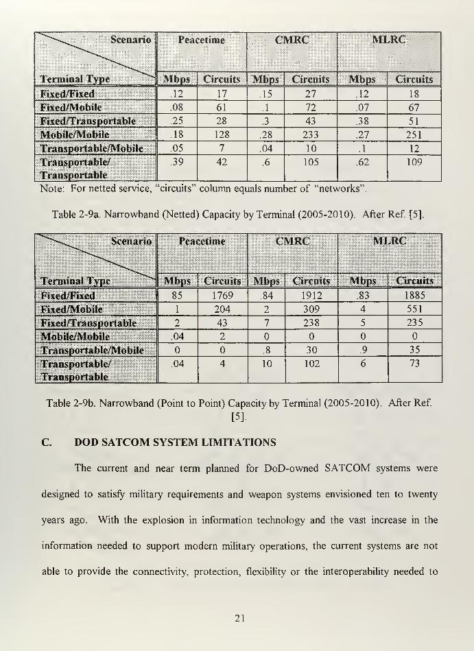
e. Terminal Capacity
DoD SATCOM terminal capacity requirements for the three operational
scenarios are depicted in Table 2-9a for Narrowband (netted) and Table 2-9b for
Narrowband (point to point). Both tables summarize the capacity between the following
categories of terminals: fixed to fixed (F/F); fixed to mobile (F/M); fixed to transportable
(F/T); mobile to mobile (M/M); transportable to mobile (T/M); and transportable to
transportable (T/T). [Ref 5: pp. 4.6 - 4.8]
20
^^'""-v^^^^^^ Scenario
Terminal Type ^^
Peacetime CMRC MLRC
Mbps Circuits Mbps Circuits Mbps Circuits
Fixed/Fixed .12 17 .15 27 .12 18
Fixed/Mobile .08 61 .1 72 .07 67
Fixed/Transportable .25 28 .3 43 .38 51
Mobile/Mobile .18 128 .28 233 .27 251
Transportable/Mobile .05 7 .04 10 .1 12
Transportable/
Transportable
.39 42 .6 105 .62 109
Note: For netted service, 'circuits" column equals number of "networks".
Table 2-9a. Narrowband (Netted) Capacity by Terminal (2005-2010). After Ref. [5].
^""*^>-,,.^^^^ Scenario
Terminal Type ^^
Peacetime CMRC MLRC
Mbps Circuits Mbps Circuits Mbps Circuits
Fixed/Fixed 85 1769 .84 1912 .83 1885
Fixed/Mobile 1 204 2 309 4 551
Fixed/Transportable 2 43 7 238 5 235
Mobile/Mobile .04 2
Transportable/Mobile .8 30 .9 35
Transportable/
Transportable
.04 4 10 102 6 73
Table 2-9b. Narrowband (Point to Point) Capacity by Terminal (2005-2010). After Ref.
[5].
C. DOD SATCOM SYSTEM LIMITATIONS
The current and near term planned for DoD-owned SATCOM systems were
designed to satisfy military requirements and weapon systems envisioned ten to twenty
years ago. With the explosion in information technology and the vast increase in the
information needed to support modem military operations, the current systems are not
able to provide the cormectivity, protection, flexibility or the interoperability needed to
21

support today's requirements let alone support tomorrow's even greater needs. In staying
within the scope of this thesis, discussion of capabilities or lack thereof will be confined to
narrowband mobile UHF communications. The capabilities which will be discussed are
replenishment of DoD SATCOM systems, connectivity, protection, access and control,
interoperability, flexibility and quality of service.
1. Replenishment of DoD-Owned Capability
DoD SATCOM systems even with planned upgrades will be unable to support the
CMRC scenario in the 2003-2008 time fi-ame, when they are finally scheduled for
replacement. The legacy systems of that time are expected to meet less than 25 percent of
DoD's forecasted need. Figure 2-1 depicts DoD SATCOM systems' anticipated life
expectancies. [Ref 6: pp. 3.1 - 3.2]
Milstar II DSCS UFO
Figure 2-1. Current MILSATCOM Life Expectancy. After Ref [6].
22

2. Connectivity
Connectivity, as discussed previously, includes both coverage and capacity. All of
DoD-owned systems are geosynchronous satellites which limits their coverage to
everywhere between 65° North and 65° South latitudes. Effectively no polar coverage is
available. And in some areas, the capacity available is insufficient to meet U.S. needs and
maintain continuous connectivity to all forces. Concerning capacity, current DoD
SATCOM systems lack the capability to meet rapidly growing capacity requirements of
tomorrow's information hungry, dynamic, flexible and mobile forces Of particular
interest, these systems cannot now and will not in the near future be able to provide the
required information throughput to small SATCOM terminals/antennas required for on-
the-move or at-the-pause communications required for battlefield information dominance.
DoD owned systems that can be used for mobile narrowband UHF communications are
MCLSTAR and UFO. Table 2-10 compares the total number of UHF circuits these
systems can support at full strength with the Peacetime Scenario Narrowband mobile
circuit requirements provided in Tables 2-9a and 2-9b. The results of this exercise shows
that DoD mobile UHF satellite capability falls well short of meeting user demands of even
the least stressful scenario. DoD SATCOM shortfall in the UHF area becomes more
pronounced if operations are concentrated in one part of the world. [Ref 6: pp. 3.2 - 3.4]
23

Calculations Totals
UHFMnSATCOM MTT,STAR (4 sat * 4 Circuits/sat) +
UFO (8 sat * 21 Circuits) =184
Narrowband Mobile
( Netted and Point to Point)
F/M(6 1+206) + M/M(128 + 2) +
T/M (7 + 0) =397
Unfulfilled Requirements1Capabilities (184) - Requirements
(397) -213
3.
Table 2-10. DoD SATCOM UHF Unfulfilled Requirements.
Protection
DoD current generation of SATCOM does not adequately protect its
communications circuits fi"om disruption or exploitation. The UHF signals used for mobile
narrowband on the move communications is extremely susceptible to jamming, detection
and interception. Satellite terminal and control segments are also not well protected
against all probable threats both physical and electronic, especially those segments that are
located abroad. [Ref 6; pp. 3.4-3.5]
4. Access and Control
DoD SATCOM system has significant force structure dedicated to managing and
control. Shortcomings do exist, however, new management techniques are being
employed to ensure that the time needed to identify, validate and support new or changed
requirements is greatly reduced. A system is in place to ensure access to SATCOM
resources on a priority basis. DoD control allows for dynamic allocation of resources to
meet changing needs. [Ref 6: pp. 3.5 - 3.6]
24

5. Interoperability
Interoperability was not considered when DoD SATCOM systems were initially
developed. Developed and optimized for specific user communities needs, DoD
SATCOM has only limited joint/combined communications interoperability. Many DoD
SATCOM systems use different frequency bands, waveforms, protocols, control concepts
and terminals. With no inter-system interoperablity, operational flexibility is limited among
users of the different systems and even the same SATCOM system because the network
resources are parceled out in fixed allocations. Finally, DoD SATCOM systems have
little if any interoperability and access to terrestrial systems as they have not yet been fijlly
integrated into the Defense Information Infrastructure (DII). [Ref 6: pp. 3.6-3.7]
6. Flexibility
Flexibility is defined as the use of SATCOM while U.S. forces are engaged in
mobile, dynamic operations across the full spectrum of conflict. Communication on-the-
move with current DoD SATCOM systems is exceedingly difficult. Today's DoD
SATCOM systems are not always optimized for the user and platform. With the diverse
types of terminals needed for use of diverse frequency bands, a warfighter would be
required to transport multiple terminals into the combat or install them on the same
platform. The current mobile terminal infrastructure is not "user friendly". Most of the
current terminals were designed to be operated by dedicated, specially trained personnel.
Finally, warfighters will out run their communications as the throughputs to ships, aircraft
25

and portable terminals will quickly overtax the current satellite constellations. [Ref. 6: pp.
3.7]
7. Quality of Service
Current systems will not meet future requirements for voice recognition and
intelligibility. DoD SATCOM systems are already beyond totally committed. Any
additional users will only exacerbate communications delays and blockages. Quality
problems, system delays and blockages greatly diminishes situational awareness and
dominant battlespace knowledge. Lack of communication will, in effect, greatly reduce
combat efficiency and threaten mission success. [Ref 6: pp. 3.7 - 3.8]
D. MOBILE USER STUDY REQUIREMENTS (MUS) WORKINGINTEGRATED PRODUCT TEAM (WIPT)
1. MUS WIPT Overview
Naval Space Command facilitated the first MUS WIPT meeting 18 March 1997
with continuing MUS meetings being scheduled periodically throughout 1997. The MUS
WIPT was tasked by the Deputy Under Secretary of Defense for Space (DUSDS), to
develop and prioritize mobile user requirements sets for a follow-on UFO architecture to
be implemented around 2005 - 2015 timeframe and to discuss commercial and military
options. Once completed, the MUS WIPT will forward requirements sets and
recommendations to an engineering committee which will explore architectural options
which will address those recommendations. The WIPT team is composed of numerous
experts in the field of requirements, military SATCOM and commercial SATCOM. Of
those experts, six members are considered voting members. Those voting members.
26
representing the Navy, Air Force, Army, Marine Corps, DISA and Joint Chiefs Staff, vote
on any items of contention throughout the meeting. The 16-17 April 1 997 meeting led to
a prioritized list of requirements and how commercial MSS stacks up against those
requirements. [Ref 7]
2. MUS WEPT Requirements
From the numerous requirements discussed, the following eight MUS WIPT
requirements were agreed upon during the April meeting:
• Assured Access - The assurance that SATCOM access will be
available when needed.
• Netted Comms - Communications, normally half duplex, which allows
all users to receive from and send to all other users. Critical to C2.
• Comms On-The-Move - Communications to highly mobile and/or
disadvantaged users that requires a small terminal to include hand held
terminals and small platform terminals (ships, boats, trucks and
aircraft).
• Joint Interoperable - The ability to exchange information services
satisfactorily between joint forces in a timely and efficient manner.
• World Wide Coverage - Communications coverage between
approximately 65° North and 65° South Latitudes.
• Point to Point Comms - Communications link from one specific node
to another specific node. Can be duplex or simplex.
• Broadcast - Simplex communications. One way transmission from a
single uplink source to an earth coverage downlink listening area. "A
one to many topology".
• Polar Coverage - Coverage that extends to the extreme northern and
southern polar regions (above 65° N and below 65° S).
Table 2-11 records the voting members rankings of the requirements listed above. [Ref 7]
27

Voting IVfembers
Required Capabilities USA USN USAF USMC JCS DISA AVG RANKAssured Access 1 1 1 2 1 1 1.17 1
Netted Comms 2 2 2 1 2 2 1.83 2
Comms On The Move 3 3 6 3 3 4 3.67 3
Joint Interoperable 4 4 7 5 4 6 5.00 4
World Wide coverage 5 5 5 7 6 3 5.17 5
Point to Point Comms 6 8 4 6 7 8 6.50 6
Broadcast 6 8 4 6 7 8 6.50 7
Polar 7 7 8 8 8 7 7.50 8
Table 2-11. Required Capabilities Voting Results. From Ref. [7].
3. MSS Satisfying MUS WIPT Requirements
Upon agreement on the eight most important requirements, multiple briefings on
current and future commercial mobile satellites were delivered to the MUS WIPT. After
lengthy discussion among the entire group, the various MSS under consideration were
rated on a red, yellow and green scale against the eight MUS WIPT requirements. Red is
for total nonsatisfaction, yellow for partial satisfaction and green for total satisfaction.
Table 2-12 lists the MSS which have been discussed previously in chapter one or will be
discussed in chapter three, and their rating versus the eight requirements. [Ref 7]
Mobile Satellite Services
Required Capabilities Imnarsat SkyceJI Globalstar Iridium ICO Eliipso Odyssey
Assured Access Red Red Ylw Red Red Red Red
Netted Comms Red Red Ylw Red Red Red Red
Comms On The Move Ylw Ylw Gm Gm Gm Gm GmJoint Interoperable Ylw Ylw Ylw Ylw Ylw Ylw Ylw
World Wide coverage Gm Red Ylw Gm Ylw Ylw Ylw
Point to Point Comms Gm Gm Gm Gm Gm Gm GmBroadcast Gm Ylw Ylw Ylw Red Red Red
Polar Red Red Red Gm Ylw Red Ylw
Table 2-12. MSS Ability to Satisfy Required Capabilities. From Ref [7].
28

E. SELECTION OF MSS FOR FURTHER STUDY
By examining Naval Doctrine, DoD FRX), DoD SATCOM shortcomings and MUS
WIPT's grading of MSS, the author has identified three systems for potential integration
into Naval Communications. Those three systems are Inmarsat, Iridium and Globalstar.
The primary reasons that Skycell, Ellipso, ICO and Odyssey were not selected for further
study is that none of them currently provide for a capability of world wide
communications coverage between 70° N and 70° S latitudes and the desire to keep the
scope of this thesis within manageable bounds. Skycell only intends on providing
coverage for North and South Amereica. The three MEO systems do not choose to
provide coverage over open ocean and polar areas. Instead, they have operational policies
which require them to concentrate the beams of their satellites on the land masses at the
expense of nonpopulated areas, such as the ocean and polar regions. If these three
systems change these policies, DoD's use of their services should be reconsidered. Table
2-13 provides further clarification why these systems where excluded. The three systems
selected will be discussed in detail in subsequent sections to include their strengths,
weaknesses, possible enhancements and potential integration into Naval communications.
29

MSS Reasons for Exclusion
Skycell • Fails to satisfy four out of eight MUS requirements.
• Fully meets only the Comms on the Move requirement.
• Most notable failure - World Wide Coverage. Initial plan is to
concentrate only on North and South America.
• Navy requires open ocean coverage.
ICO • Fails to satisfy three out of eight MUS requirements.
• Fully meets only Comms on the Move requirement and Point to Point
Comms.
• Most notable failure - listed as yellow for World Wide coverage,
however, has no current plan to provide open ocean or polar coverage
• Navy requires open ocean coverage
Ellipso • Fails to satisfy four out of eight MUS requirements.
• Fully meets only Comms on the Move requirement and Point to Point
Comms.
• Most notable failure - listed as yellow for World Wide coverage,
however, has no current plan to provide open ocean or polar coverage.
• Navy requires open ocean coverage.
Odyssey • Fails to satisfy three out of eight MUS requirements.
• Fully meets only Comms on the Move requirement and Point to Point
Comms.
• Most notable failure - listed as yellow for World Wide coverage,
however, has no current plan to provide open ocean or polar coverage.
• Navy requires open ocean coverage.
F.
Table 2-13. Reasons for MSS Exclusion. From Ref [7].
DOD UHF SYSTEMS VS MSS
DoD UHF Systems (Milstar and UFO) as discussed before cannot meet the
demand for their services. Secondly, being UHF systems they inherit that frequency bands
limitations, specifically, its vulnerabilities to jamming, detection and exploitation. These
systems also require more powerful specialized transceivers requiring dish antennae or
other directional antennae limiting its mobility. Finally, using the MSS WTPT required
capabilities, DoD UHF systems do not fully meet all of the MSS WIPT requirements with
30

the assured access being a yellow because DoD does control the satellites, but the
satellites UHF capacities are severely limited. Table 2-14 compares DoD UHF Systems
versus MSS systems overall against the MSS WIPT required capabilities. The results
indicate that though MSS is no panacea, DoD UHF Systems cannot fully meet all of the
MUS WIPT requirements either. Most notably, true communications on the move is a
problem area and DoD UHF Systems totally fail to meet Joint Interoperable and Polar
requirements.
Required Capabilities DoD UHFSystems
MSS Totals
Assured Access Yellow Yellow
Netted Comms Green Yellow
Comms On The Move Yellow Green
Joint Interoperable Red Yellow
World Wide coverage Green Green
Point to Point Comms Green Green
Broadcast Green Yellow
Polar Red Green
Table 2-14. Using MSS WIPT Requirements to compare DoD UHF Systems & MSS.
31

32

in. OVERVIEW OF COMMERCIAL MOBILE SATELLITE SERVICES
A. SPACE COMMUNICATIONS
1. Space Segment
The space segment of a satellite system is composed of a satellite's subsystems,
orbit and the frequency bands in which it operates. A satellite consists of seven main
subsystems which affect the overall performance and design life of a satellite. As with all
complex systems, performance and design issues must be addressed by making necessary
trades between the various subsystems. The subsystems from which trades must be made
are described in Table 3-1. [Ref 8: pp. 2-2]
1^ Subsystem Function |
Antenna Enables Transmission and Reception ofRadio Signals
Transponder Converts Uplink Signal to Downlink Signal
Attitude Maintains Acceptable Orientation of Satellite
Propulsion Maintains Satellite within Acceptable Orbital Tolerances, Assists in
Maintaining Attitude
Electrical Power Generates, Stores, and Distributes Electricity Throughout the
Satellite
Telemetry,
Tracking, and
Control (TTi&C)
Enables Ground Control of Subsystems, Monitoring of Subsystems,
and Satellite Tracking
Thermal Control Maintains Requisite Operating Temperatures of Subsystems
Table 3-1. Satellite Subsystems. From Ref [8]
A satellite's orbital regime directly affects coverage area, size of each satellite, cost
of each satellite, the number of satellites necessary to provide similar services and the size
of the antenna necessary to receive equivalent signals. Geostationary orbits (GEO) are
33
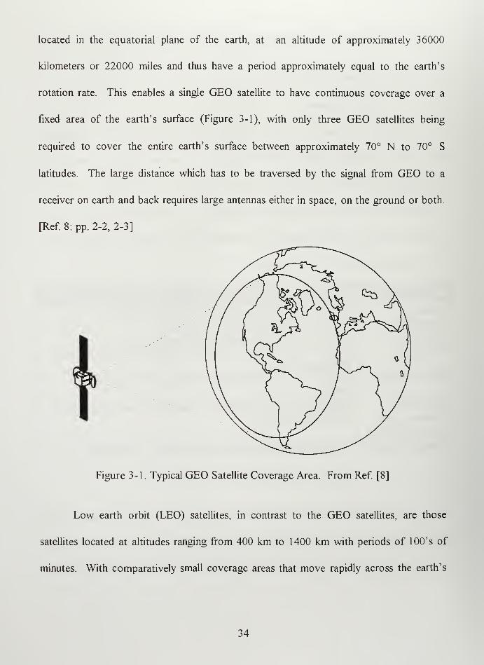
located in the equatorial plane of the earth, at an altitude of approximately 36000
kilometers or 22000 miles and thus have a period approximately equal to the earth's
rotation rate. This enables a single GEO satellite to have continuous coverage over a
fixed area of the earth's surface (Figure 3-1), with only three GEO satellites being
required to cover the entire earth's surface between approximately 70° N to 70° S
latitudes. The large distance which has to be traversed by the signal from GEO to a
receiver on earth and back requires large antennas either in space, on the ground or both.
[Ref 8: pp. 2-2, 2-3]
Figure 3-1. Typical GEO Satellite Coverage Area. From Ref [8]
Low earth orbit (LEO) satellites, in contrast to the GEO satellites, are those
satellites located at altitudes ranging from 400 km to 1400 km with periods of lOO's of
minutes. With comparatively small coverage areas that move rapidly across the earth's
34

surface, LEOs require a greater number of satellites to obtain the same coverage as a GEO
satellite (Figure 3-2). However, given the correct number of satellites with the
appropriate inclination, a LEO system can provide continuous worldwide coverage even at
the poles.
Figure 3-2. Numerous LEO Coverage Areas within GEO Footprint.
LEO satellite signals suffer a much lower free space loss (FSL) than GEO signals. In
satellite communications, FSL represents the communications link loss in free space
(vacuum). The lower FSL experienced by LEO satellites enables LEO terminals to be
much more compact when compared to GEO terminals. Finally, there is a signal delay
which increases with a satellite's distance from earth. This delay is approximately 0.018
seconds for round trip communications via a LEO satellite and about 0.5 second delay for
35

round trip communications via a GEO satellite. The FSL for various satellite frequencies
at typical GEO and LEO altitudes are presented in Table 3-2. [Ref. 8: pp. 2-10, 2-11]
Free Spi^e Loss
Band Name Frequency GEOSatellites
(35,800 km)
LEOSateliites
(750 km)
L 1.5 GHz 187.0 dB 153.5 dB
S 3.0 GHz 193.1 dB 159.5 dB
C 6.0 GHz 199.1 dB 165.5 dB
X 10.0 GHz 203.5 dB 169.9 dB
Ku 15.0 GHz 207.0 dB 173.5 dB
K 25.0 GHz 211.5 dB 177.9 dB
Table 3-2. Free Space Loss for a GEO and LEO Satellite. After Ref [8].
The satellite frequency bands listed in Table 3-2 are set by the International
Telecommunications Union (ITU). Each frequency band is associated with particular type
of services authorized by the ITU (Table 3-3). Among these services are fixed satellite
services (FSS) which refer to large fixed antenna terminals, mobile satellite services (MSS)
referring to low data rate mobile terminals and broadcast satellite services which are high
data rate one-way broadcasts to very small aperture terminals. For the three systems
analyzed in this thesis, L-Band and S Band will be utilized. The advantages of these
bands are the small to moderate antenna size required and the negligible atmospheric
effects. Disadvantages include moderate-to-low data capacity and susceptibility to
jamming. [Ref 9: pp. 5-26]
36

BandDesignation
Frequency
RangeServices M
L - Band 1 GHz - 2 GHz FSS, MSS, BSS and Microwave Communications
S - Band 2 GHz - 4 GHz FSS, MSSC - Band 4 GHz - 8 GHz FSS, MSS - terrestrial radio relay microwave
systems
X - Band 8 GHz - 12 GHz FSS, MSS - terrestrial mobile services.
Government and Military services especially USand Russia
Ku - Band 12 GHz- 18
GHzFSS, MSS, BSS
K - Band 18 GHz -27
GHzFSS
Table 3-3, Radio Frequency Bands Used for Satellite Communications. After Ref [9].
2. Ground Segment
The ground segment is a complex system which is comprised of three categories of
earth terminals ~ fixed, mobile and earth terminal centers. Feederlink, hub, gateway, base
and remote antennas are examples of fixed terminals. Included in the mobile terminals
category are vehicle mounted, portable, handheld, messaging, remote data and paging.
Earth terminal center supports various fianctions of the satellite system. Typical earth
terminal processing centers are Network Control Center, TT&C Center and the Data
Communications Center. Table 3-4 summarizes the different terminal and system center
types, their fijnctions, and their characteristics.
37
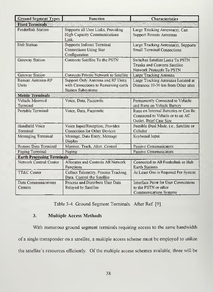
Ground Segment Types | Function | Characteristics
Fixed Terniinals
Feederlink Station Supports all User Links, Providing
High Capacity Communications
Link.
Large Tracking Antenna(sj, Can
Support Remote Antennas
Hub Station Supports Indirect Terminal
Cormections Using Star
Configuration
Large Tracking Antenna(s), Supports
Small Terminal Connections
Gateway Station Connects Satellite To the PSTN Switches Satellite Links To PSTNTrunks and Converts Satellite
Network Protocols To PSTNGateway Station Connects Private Network to Satellite Large Tracking Antenna
Remote Antenna-RF
Units
Support Only Antenna and RF Units
with Connections to Remaining earth
Station Subsvstems
Large Tracking Antennas Located at
Distances 10-30 km from Other sites
Mobile Terminals
Vehicle Mounted
Terminal
Voice, Data, Facsimile Permanently Connected to Vehicle
and Rims on Vehicle Battery
Portable Terminal Voice, Data, Facsimile Runs on Internal Batteries or Can Be
Coimected to Vehicle or to an ACOuUet. Briefcase Size
Handheld Voice
Terminal
Voice Input/Reception, Provides
Connection for Other Devices
Possible Dual Mode, i.e.. Satellite or
Cellular
Messaging Terminal Message, Data Entry, Message
Display
Keyboard Input
Remote Data Terminal Monitor, Track, Alert, Control Passive Communicators
Paging Terminal Paging Passive Communicators
Earth Processmg Terminals
Network Control Center Allocates and Controls All Network
Functions
Connected to All Feederlink or Hub
Earth Stations
TT&C Center Collect Telemetry, Process Tracking
Data, Control the Satellite
At Least One is Required Per System
Data Communications
Centers
Process and Distribute User Data
Relayed by Satellite
Interface Point for User Connections
to the PSTN or other
Communications Systems
Table 3-4. Ground Segment Terminals. After Ref. [9].
3. Multiple Access Methods
With numerous ground segment terminals requiring access to the same bandwidth
of a single transponder on a satellite, a multiple access scheme must be employed to utilize
the satellite's resources efficiently. Of the multiple access schemes available, three will be
38

considered ~ Frequency Division Multiple Access (FDMA), Time Division Multiple
Access (TDMA) and Code Division Multiple Access. Table 3-5 briefly describes
advantages and disadvantages of FDMA, TDMA and CDMA which will be discussed in
more detail in the following subsections. [Ref 8: pp. 2-18]
Access Methods Advantages Disadvaotages
CDMA Allows ranging, multipath mitigation,
random access, soft hand-off, LPl/LPD,
jam resistant, high frequency reuse
Complex, hardware, needs accurate
power controls, high data rates are
difficult
FDMA Simple hardware, no synchronization
needed between channels
Multiple carriers can cause
intermodulation distortion, reallocations
difficult, low reuse, hard hand-offs,
fading sensitive
TDMA Efficient use of power All channels must be synchronized,
complex hardware, low reuse, hard hand-
offs, fading sensitive
Table 3-5. Access Method Advantages and Disadvantages. From Ref [8].
a. Frequency Division Multiple Access (FDMA)
FDMA is characterized by frequency separation of signals. A satellite's
transponder's available bandwidth is divided into frequency band segments where each
segment is assigned to a user. Each earth station is assigned a specific uplink and
downlink frequency. The number of segments can vary from one, where an entire
transponder is assigned to a single user, to literally hundreds of segments. To avoid
cochannel interference and intermodulation problems between multiple users, a network
manager has to 'balance" the power and ensure proper spacing between carriers. Figure
3-3 demonstrates the concept ofFDMA. [Ref 10: pp. 394]
39

^^ A^^^^^^ A Data
AData.
Data- -
B B BData
C
Data Data
sData C^^ Data CData
Data
^.
Data
Frequency
Channel One
Frequency
Channel Twc
Frequency
Channel
Three
Figure 3-3. Frequency Division Multiple Access.
b. Time Division Multiple Access (TDMA)
TDMA allows many users to communicate on the same frequency but at
different times. In TDMA, a single user is allowed to send a single signal to the satellite in
a time interval called a time slot. At the end of this slot, another user repeats the process
in the next time slot. This continues until all users have used at least one time slot. The
aggregate total of these time slots is called a time frame, and this frame is then repeated.
In this way, multiple users communicate on the same frequency, and avoid interference
with each other by communicating at slightly different times. Figure 3-4 demonstrates the
concept ofTDMA. [Ref 8: pp. 2-18, 2-19]
40

Figure 3-4. Time Division Multiple Access.
c. Code Division Multiple Access (CDMA)
CDMA the signals of multiple users access the satellite simultaneously.
Each signal uses the same carrier frequency and occupies the full carrier bandwidth, but
the individual carriers are identified by means of a unique code assigned to them. The data
is superimposed onto a specific coded address waveform. The combined signal is
modulated onto a radio frequency carrier, producing signals that are 'Spread" across the
41

frequency bandwidth of the transponder. The CDMA receiving earth station is
programmed to ignore all but signals carrying the correct code. CDMA's "spread"
spectrum characteristics give it a distinct advantage in applications requiring LPI/LPD and
jam protection. Figure 3-5 demonstrates CDMA and is followed by Figure 3-6 which
compares the three multiple access schemes. [Ref 9: pp. 5-31]
Figure 3-5. Code Division Multiple Access.
42

FDMAtw
-T
^ f
W
Frame length
Time frequency
plane CDMAtw
-T
Figure 3-6. FDMA, TDMA and CDMA in the Time-Frequency Plane. From Ref. [10].
B. INMARSAT
1. System Overview
International Mobile Satellite Organization (Inmarsat) is a 79 member-state co-
operative which operates a satellite system providing world wide (approximately 70° N
latitude to 70° S latitude) telephone, telex, data and fax services to international shipping,
aviation, offshore and land mobile industries. Inmarsat began in 1979 with the investment
share of each member nation to be related to both the tonnage of ships registered and the
volume of communications to and from it. The investment shares are adjusted yearly to
43

reflect the actual use of the system. In recent years, the major shares have been about 25
percent for the United States, 14 percent for the United Kingdom, 12 percent for Norway,
and 9 percent for Japan. Comsat Corporation is the US representative in Inmarsat. Since
Inmarsat began global operations, over 46,000 Inmarsat terminals have been sold and the
demand is still rising. The Inmarsat system can be broken down into two segments —
space and ground. [Ref 11 : pp. 116]
a. Space Segment
Inmarsat provides world wide satellite communications coverage from
approximately 70° N to 70° S latitudes. Inmarsat's space segment is composed of a
constellation of eight satellites in geosynchronous orbit located approximately at 55.5° W,
15.5° W, 64.5° E and 180° E longitude. The satellite coverage areas are the Atlantic
Ocean Region West (AOR-W), Atlantic Ocean Region East (AOR-E), Indian Ocean
Region (lOR), and Pacific Ocean Region (POR). The eight satellites are equally
subdivided between the four operational areas with one active satellite and one on station
spare at each location (Figure 3-7). [Ref 12: pp. 313]
44

Figure 3-7. Inmarsat Satellite Coverage Areas. After Ref. [12].
Inmarsat's spare satellites are mainly composed of Inmarsat II satellites.
Inmarsat II satellites uses L-Band for communication with ships and C-band for
communication with shore stations. Inmarsat II satellites use a hexagonal array of 61
elements to provide a global L-Band beam which can compensate for losses, which
increase as the ship terminal elevation to the satellite decreases. For C-Band, each satellite
has two seven-element arrays one for transmission and one for reception. One C/L-Band
channel is used for shore to ship communications with 16 MHz bandwidth and four L/C-
Band channels being used for ship to shore communications at 4.5 MHz bandwidths with a
minimum of 25 dBW. The total capacity per satellite is 250 two-way voice circuits.
Launched from between 1990 and 1992 each satellite has an estimated lifetime of 10
years, but with the introduction of the Inmarsat Ills, Inmarsat lis are being relegated to
the roll of "hot spares". [Ref 1 1: pp. 1 1 1-1 12]
45

Inmarsat III satellites were not rushed into production because of the
lifetime limitation of Inmarsat II, but by Inmarsat IPs capacity limitations. With the
interest in mobile communications on the rise, Inmarsat III satellites were developed to
provide a capacity ten times that of Inmarsat II. Global, high power multiple spot beams
will continue to support Inmarsat III types of services as well as provide newer mobile
personal communications services and L-band to L-band communications via laptop size
and smaller terminals. These spot beams will cover the majority of North America, South
America, the Atlantic Ocean, Africa, Europe and the Far East (Figure 3-8).
Figure 3-8. Inmarsat III Spot Beams. After Ref [11].
A global spot beam was included to provide coverage between the spot beam coverage
gaps and to provide to continued support for transoceanic users. The satellhes will be
able to re-allocate power and bandwidth between the five spot beams and the single global
beam to dynamically meet changing traffic requirements. Each Inmarsat III satellite has a
46

design life of 1 3 years. Three Inmarsat Ills are on station with the last satellite scheduled
for launch late 1997. Inmarsat Ill's characteristics are described in Table 3-6. [Ref 1 1
:
pp. 113-115]
Configuration Transmitter Receiver Antenna if
- C-band to L-band -C-Band. 3600 to 3629 -C-Band: 6435 to 6454 - C-band: Two global
forward channel, 19 MHz (L to C, and C to MHz (C to L, C to C), coverage horns (1
bands with a total 64.5 C), 3629.4 to 361.6 6454.4 to 6456.6 MHz transmit, 1 receive),
MHz bandwidth MHz (Nav). solid state (Nav). G/T-13dB/K each with dual circular
- L-band to C-band power amplifiers. EIRP -L-band: 1626 to polarization.
retiim channel, 19 27 dBW (1 to C, and C 1630.5 MHz and 1631.5 - L-band: two offset fed
bands with a total 64.5 to C), dBW (Nav) to 1660.5 MHz (L to C, deployed reflectors for
MHz bandwidth - L-band: 1525 to 1529 L to L). One low-noise global and spot beams- C-band to C-band MHz and 1530 to 1559 amplifier per antenna (1 transmit, 1 receive).
administrative channel. MHz (C to L, L to L), feed. G/T-11.5dB/K approximately 7.5ft
0.9 MHz bandwidth. 1574.4 to 1576.6 MHz (global beam), -5.5 diameter, each with 22
- L-band to L-band (Nav). Twenty-two dB/K (spot beam) cup-helix feeds, > 24.3
mobile channel. 1 MHz solid state power dB edge of coverage
bandwidth amplifiers, 440 W total gain for spot beams (C
- C-band to C-band and output (C to L, L to L). to L) and > 19.2 dB
L-band navigation Redundant 17 W solid peak gain for global
channel, 2.2 MHz state amplifiers (Nav). beam (C to L, L to L),
bandwidth EIRP 48 dBW split in circular polarization;
any proportion between one 27 inch diameter
spot and global (C to L, center fed parabolic
L to L), 27.5 dBW(Nav) reflector (nav), 15.8 dB
edge of coverage gain
Table 3-6. Inmarsat III Characteristics. After Ref [U].
b. Ground Segment
The ground segment can be broken down into Sliip Earth Stations (SES),
Land Earth Stations (Gateways), Network Coordination Stations (>JCS) and a Network
Operations Center (NOC). The SES used by the Navy for shipboard mobile satellite
services are Inmarsat A and Inmarsat B. Gateways are owned and operated by Inmarsat
members, however Navy contracts exclusively with US owned and operated Comsat for
47

Inmarsat A and B services and routes its calls through one of Comsat's four Gateways.
NCS are owned located at Fucino, Italy; Southbury, Connecticut; Santa Paula, California
and Beijing, China. The NOC is located in London, UK [Ref 1 1 : pp. 116]
The main difference between Inmarsat A and Inmarsat B is that A is an
analog system and B is a digital system. The digital difference enables Inmarsat B to
provide a substantial cost savings when compared to Inmarsat A. Additionally, Inmarsat
B provides a path for future interoperability with Integrated Services Digital Network
(ISDN). Both terminals perform similar functions, provide similar services and are of
comparable size. The functions performed by Navy SES are reception and transmission of
signaling messages, duplex telephony service, reception of Inmarsat Service
Announcements, acknowledgment of shore-originated simplex call service, automatic
distress testing capability, and priority request for establishing distress calls. Services
provided by Inmarsat A and B are summarized in Table 3-7.
SERVICE DATARAIE
NUMBERPOSSIBLE
Voice 9.6 kbps 5
Facsimile 9.6 kbps 5
Telex 75 bps 740
Low Speed Data 9.6 kbps 5
High Speed Data 56 kbps 1
Video
Teleconferencing
56 kbps 1
Compressed Video 56 kbps 1
Paging 1200 kbps 45
Broadcast/Group
Calls
9.6 kbps 5
Table 3-7. Inmarsat A and B SES services. After Ref [13]
48

Standard Maritime equipment for Inmarsat A and B SES include a 1016 mm stabilized
parabolic directional antennae housed in a 1244 mm by 1350 mm radome, inside maritime
equipment and the users equipment ~ fax machines, PBX, phones, encryption devices,
computers ... (Figure 3-9). [Ref 14: pp. 3 ]
1350 mm
1244mm
FAXTelex/Printer
Maritime Equipment
Phone Personal Computer
Figure 3-9. Inmarsat A and B Standard Configuration. After Ref [14].
Gateways process requests received from ships over a ship-to-shore
'i^equest" channel and from shoreside parties over the terrestrial trunks. For ship
originated single channel per carrier (SCPC) calls the SES request message is received by
the addressed Gateway which relays the request to the NCS for channel assignment; the
NCS thereby assigns a channel in the appropriate satellite spot beam is available or a
global beam channel is assigned if the appropriate spot beam frequency is not available.
The NCS transmits the channel assignment to both the Gateway and SES. For shore
49

originated SCPC calls the Gateway requests the NCS to transmit a call announcement
message to the required SES which then responds to the NCS. The NCS thereby assigns
a channel in the appropriate satellite spot beam is available or a global beam channel is
assigned if the appropriate spot beam frequency is not available. The NCS transmits the
channel assignment to both the Gateway and SES. For ship originated TDMA calls, the
SES request message is received by the addressed Gateway which then performs the
assignment function and transmits the assignment message to the SES and NCS. For
shore originated TDMA calls, the Gateway requests the NCS to transmit a call
announcement message to the SES which then responds to the NCS. The NCS relays the
SES response information to the Gateway which then performs the assignment function
and transmits the assignment message to the SES and NCS. The Gateway provides
support of duplex telephony, telex, transmission and reception of signaling messages,
priority establishment, time slot assignments, requests frequency assignments, interstation
signaling with the NCS, maintaining access control tables, commissioning SES
installations, data reporting to Inmarsat and stand alone capability option in case of NCS
failure. [Ref 15: pp. F-3]
Network Coordination Stations (NCS) are located at designated
(collocated Gateway's and interface with the space segment at C-band and L-band for the
purpose of signaling with SES and Gateways as appropriate and for overall network
control and monitoring. NCS provides assignments for SCPC services and acts as back-
up to Gateways handling ship originated distress calls. NCS monitors all signaling
50

channels received by the SESs. For spot beam operation the NCS carrier and spot beam
identification are provided by the NCS bulletin board to permit spot beam identification
for signaling units establishing calls. NCS transmits the NCS carrier for each spot beam to
enable the SES to determine the appropriate spot beam identity. NCS determines the SES
EIRP level on a call by call basis depending on the operational satellite; channel
assignment in the spot or global beam and transmits the EIRP level in the assignment
message. For TDMA channels the Gateway performs a similar function. The NCS
processes all signaling messages (to Gateway and SES) on a first-come first-serve basis
except those associated with priority distress calls. NCS fiinctions include transmission
and receptions of signaling messages, interstation signaling, channel assignment for SCPC,
network monitoring. Maintain telephone and High Speed Data Service (HSD) list which
indicates which charmels are in uses as well as Gateway and SES using each channel. [Ref
15:F-4]
The Network Operations Center (NOC) is located at Inmarsat
Headquarters located in London, UK. At that facility the capability exists for centralized
monitoring provided by the monitor and test capabilities of Inmarsat's NCSs. NOC
typically provides resource allocation of the space segment resources to NCS and
Gateway earth stations where required. [Ref 15: pp. F-5 ]
2. System Strengths
The Navy has contracted Inmarsat services through US signatory Comsat since
1990. Article 3(3) of the Inmarsat Convention states that Inmarsat Organization '^hall act
51

exclusively for peaceful purposes". While at first glance 'peaceful purposes" may seem to
preclude military use of Inmarsat services, it has been determined that 'peaceful purposes"
does not exclude military activities so long as those activities are consistent with the UN
Charter. This interpretation has allowed Inmarsat to install SES aboard warships
Currently, Inmarsat SESs are installed in over 150 Navy ships. In the near future, every
ship in the Navy from FFGs to CVNs will be outfitted with at least one Inmarsat SES.
Inmarsat SESs have proven their usefulness in providing direct dial phone services, high
quality images, video teleconferencing, video products, BDA reports and weapons
targeting in numerous Navy operations from the Gulf War to operations in Bosnia and
beyond. [Ref 16: pp. 1]
COMSAT earth ground stations are located in Santa Paula CA (Pacific Ocean and
Western Atlantic satellite), Southbury, CT (Western and Eastern Atlantic satellites),
Anatolia, Turkey (Eastern Atlantic and Indian Ocean satellites) and Eurasia, Thailand
(Indian Ocean and Pacific Satellites). The COMSAT ground stations are all linked via
fiber optic cables. A Navy vessel's Inmarsat SES call is routed through one of these
COMSAT owned ground stations, relayed via fiber optic cable to another Comsat owned
gateway, over another Inmarsat satellite if the vessel is making a ship to ship call, relayed
on to a Conus gateway where call will be routed either to a leased line or the public
switched telephone network depending on the calls ultimate destination (Figure 3-10).
[Ref 13: pp. 3-5]
52

^_z
Figure 3-10. Comsat Fiber Relay Network. After Ref. [17].
The closed network formed by the Comsat fiber relay network provides the Navy
with a more secure mode of communications between its widely dispersed forces rather
than having to rely on numerous foreign owned Gateways. The Navy is the single largest
user of Inmarsat services and is allied with Comsat, Inmarsat's largest shareholder. These
two factors reflect positively on the Navy obtaining new services and being able to modify
existing services to better meet its needs. For example, the Navy has been encrypting data
passed over Inmarsat utilizing a STU III encryption device connected to the analog
Inmarsat A something it would not be able to do over the new all digital Inmarsat B. At
no additional research cost to the Navy, Comsat identified the problem and began work
with governmental agencies to ensure STU III technology would be incorporated in
53

Inmarsat Bs. Table 3-8 describes a number of requirements which Comsat helped the
Navy satisfy with existing, modified or new services. [Ref 17: pp. 4-5]
Requirement Service
Netted Communications Group Calls
Telemedicine High Speed Data Service (HSD)
Battle Damage Assessments HSDVideo Teleconferencing Compressed Video via HSD
GENSUR & SI Message Rebroadcast Broadcast
Situation Awareness Rebroadcast Compressed Video ofCNNLogistics Support Low Data Rate Service used for SALTSWeapons Data HSD
Moral Welfare Recreation AFRTS Radio Beast/Sailor Phone
Table 3-8. Navy Requirements Satisfied by Inmarsat.
3. System Weaknesses
Inmarsat's weaknesses are inherent in most commercial systems. Those
weaknesses are cost of service, assured access and system vulnerabilities. The cost of
Inmarsat's services depends on data rate and on whether you are calling ship to ship, ship
to Conus or ship to out of Conus. Naturally, the higher the data rate the more bandwidth
you need so the more you pay. A ship to ship direct call will add the greatest cost as it
involves at least one gateway and two satellite hops ~ ship to satellite to gateway to
satellite to ship. A ship to out of Conus is the next highest on the cost scale as Comsat
fiber network brings the call back to the US and into the public switched network for one
fee with an additional charge being added for the international call from Conus. Finally, a
ship to Conus call will be the lowest flat rate with no hidden charges as once the call is in
54

the US no additional charge will be assessed. The cost of Inmarsat A's all analog services
is substantially higher than the cost for Inmarsat B's all digital services and is a driving
factor in the Navy's decision to replace all Inmarsat As over the next five years. Table 3-9
compares the costs associated with Inmarsat A and B services. [Ref 18: pp. 2-5]
PRODUCT INMARSAT ACOST
INMARSATBCOST
DIFFERENCE:!
Voice /Low Data Rate/Fax Service (* add cost of long distance if overseas call)
Ship to Conus $5.90/min * $2.85/min* $3.05/min*
Ship to Ship $11.90/min $4.35/min* $7.55/min
High Speed Data Service (* add cost of long distance if overseas call)
Simplex Ship to Conus $7.90/min* $5.95/min* $1.95/min*
Simplex Ship to Ship $15.80/min $11.90/min $3.90/min
Duplex Ship to Conus $11.25/min* $9.00/min* $2.25/min*
Duplex Ship to Ship $22.50/min $18.00/min $4.00/min
Table 3-9. Inmarsat A and B Service Costs.
Access with Inmarsat as with all commercial systems can be a potential problem
unless you lease or buy a transponder. Otherwise, you must compete for access on an
equal basis with other paying Inmarsat customers. If the satellite or Comsat Gateway are
overloaded the caller will get a busy signal until a channel becomes available to them.
Over open ocean, access is readily available. However near a busy coastline or in a
remote hot spot with little terrestrial infrastructure assured access is tenuous at best.
Inmarsat historically has had a very good access rate, meaning when you want to make a
call you can, of between 95 and 98 percent in off areas and 85 to 93 percent in congested
areas. These rates will become even better over the next few months as the remaining
55

Inmarsat Ills come on line with their fixed spot beams and ability to reallocate bandwidth
and power dependent on traffic patterns. [Ref 9: pp. 30-33]
Commercial satellites are vulnerable to threats of hostile jamming, detection
interception and geolocation because the commercial world trades protection for
bandwidth. Jamming of a geosynchronous satellite can be done with components obtained
from a local electronics store as was proven when a gentleman in the US jammed an cable
company satellite channel using a microwave and a trash can lid. Detecting a TDMA and
FDMA signal can be easily done with the correct location, a little knowledge and a
spectrum analyzer. With a little more effort, interception can also be accomplished,
however, STU III encrypted information would be unintelligible. Finally, geolocation
would take much more skill and effort on the part of an adversary, but remains well within
the abilities of many. In fact, Inmarsat provides additional help for the adversary
attempting to geolocate or track Navy ships at sea. If a ship leaves their Inmarsat on after
completion of a call, the ship can be geolocated to under a hundred miles simply by
someone calling the ship and receiving a ring back. [Ref. 8: pp. 2-18 , 2-19]
B. IRIDIUM
1. System Overview
Motorola pioneered the idea of a Low Earth Orbit (LEO) system which would
provide worldwide telephone service providing a dial tone anywhere at anytime. The
original concept as visualized in 1988 contained 77 Satellites. Hence the name 'Iridium"
was selected, since the element iridium is the periodic table has the atomic number 77.
56

The name has stuck even though the number of active satellites has been reduced to 66
with a System Control Segment, gateways, intersatellite links and handheld phones
completing the system. Iridium Inc. is an international corporation with US based
corporation Motorola maintaining the largest share (18%) with the remaining shares
(83%) divided between other corporations in the United States, Africa, Canada, China,
India, Middle Ease, South America, Russia, South Korea, Japan, Taiwan, Italy, Thailand
and Germany. Iridium was granted a full Federal Communications Commission (FCC)
license in January, 1995 for operations in the United States with landing rights around the
world being successfully negotiated separately with host nations. Launch services are
being provided by China, Russia and U.S. based launch facilities. Motorola, Lockheed-
Martin, Raytheon COM DEV, Bechtel, Scientific Atlanta and Siemens are producing
Iridium system components. Initial launch dates have slipped until the spring of 1998.
Projected initial operational capability (IOC) is the fall of 1999 with full operational
capability not expected until fall 2000. [Ref 19: pp. 1-2, 5-6]
The Iridium system uses Groupe Special Mobile (GSM) telephony architecture to
provide a digitally switched telephone network enabling global roaming. A subscriber will
be assigned a personal phone number. The Iridium system determines the user's location
and in turn the network charges at the appropriate rate for that location will be levied on
that personal phone number. Besides voice traffic. Iridium will support paging data traffic
and facsimile. Iridium's key system design feature is a constellation of low earth orbiting
satellites interconnected with four crosslinks per satellite creating a call routing network in
57
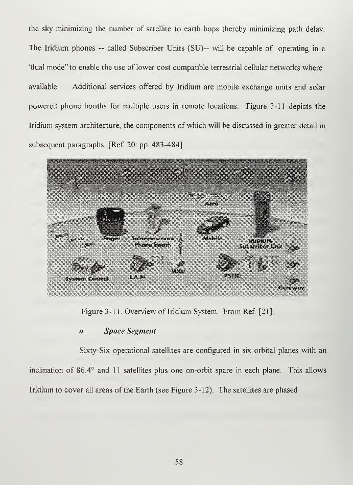
the sky minimizing the number of satellite to earth hops thereby minimizing path delay.
The Iridium phones — called Subscriber Units (SU)— will be capable of operating in a
"dual mode" to enable the use of lower cost compatible terrestrial cellular networks where
available. Additional services offered by Iridium are mobile exchange units and solar
powered phone booths for multiple users in remote locations. Figure 3-11 depicts the
Iridium system architecture, the components ofwhich will be discussed in greater detail in
subsequent paragraphs. [Ref 20: pp. 483-484]
*3RSWm 'C^wiinsJ
Ocstew«3v
Figure 3-11. Overview of Iridium System. From Ref [21].
a. Space Segment
Sixty-Six operational satellites are configured in six orbital planes with an
inclination of 86.4° and 1 1 satellites plus one on-orbit spare in each plane. This allows
Iridium to cover all areas of the Earth (see Figure 3-12). The satellites are phased
58

Figure 3-12. Iridium Instantaneous Coverage Areas. After Ref [22].
appropriately in co-rotating planes up one side of the earth, across the poles, and down
the other side of the earth. These co-rotating planes are separated by 3 1.6 degrees. The
satellites orbit at a mean altitude of 780 km (see Figure 3-13).
Figure 3-13. Iridium Satellite Constellations. From Ref [23].
59

Full Earth coverage is enabled by three L-band antennas which form a honeycomb pattern
of48 beams below each satellite. As the satellite beam footprint moves over the ground,
the subscriber signal is switched from one beam to the next or from one satellite to the
next in a hand-off process. As the satellites approach the poles, their footprints converge
and the beams overlap. [Ref 24: pp. 4. 15-4. 16]
All routing is done completely by the space network enabled by Iridium's
crosslink technology. Iridium is the first mobile satellite system to incorporate
sophisticated digital onboard processing on each satellite and the crosslink capability
between satellites (see Figure 3-14).
"-iiw^
Sfruciu««
'CotEftmu nioafioB"s Sedion
Ooteway Aaieftftfits
Figure 3-14. Iridium Satellite. From Ref [21]
The four crosslinks, and the feeder links connecting satellites to gateways, operate at K-
Band frequencies. These intersatellite links together with the gateway links operate in
packetized Time Division Multiplexing mode. The service links connecting subscriber
60

units to the satellites operate in L-Band frequencies in the narrowband TDMA/FDMA
mode (see Figure 3-15).
Figure 3-15. Iridium Satellite Links. From Ref. [21].
The L-Band communication service links operate in the 1610-1626.5 MHz
band. The total occupied bandwidth is 5.15 MHz. Modulation is quadrature phase shift
key (QPSK). With 80 circuits per beam 48 beams per satellite 3,840 circuits are possible
per satellite. With a total of 66 satellites in the system 253,440 channels are possible with
1.2 Gbps being the total system throughput possible. Both uplinks and downlinks operate
in the L-band, using Time Division Duplexing (TDD). All K-Band links—uplink,
downlink, and crosslinks—are packetized TDM/FDMA using QPSK modulation. Coded
data rates for the gateways and satellite control facility links are 6.25 Mbps, with the
crosslinks operating at a higher data rate of 25 Mbps. Crosslinks allow for reduced ground
infrastructure requirements, enable least cost routing, and permit fiill global coverage
(including the oceans). Iridium's satellite frequency bands are described in Table 3-10.
[Ref 24: pp. 4.20-4.25]
.61

Type ofLink Frequency Bands
K-Band Down-Links 18.8-20.2 GHzK-Band Up-Links 27.5-30.0 GHzK-Band Crosslinks 22.55-23-55 GHz
L-Band Service Links 1610-1626.5 MHz
Table 3-10. Iridium Satellite Frequency Bands.
b. Ground Segment
The ground segment consists of system control segment, gateway segment
and user segment. The system control segment is composed of the mission control facility
(MCF), the system engineering control facility (SCF) and the system control sites (SCS).
The mission control facility is responsible for operation and control of the Iridium's
satellites. Initially, Chandler, Arizona will handle MCF responsibilities for the first 40
satellites before transferring control to Lansdowne, Virginia. Chandler, Arizona will then
revert to its primary mission as a SCF responsible for providing engineering support and
anomaly resolution. The final portion of the system control segment, SCS, functions as
the conduit between the satellite and the MCF. Iridium satellites will always remain in
contact with one of the SCSs in the network. Telemetry data will be sent directly from the
satellite to an SCS which will then relay the data to the MCF. There are two primary
SCSs in Canada one of which provides the additional function as Iridium's main gateway
keeping track of all Iridium's billing information. A SCS located in Waimea, Hawaii will
be used by the SCF during the launch phase. Other SCSs include Rome, Italy which also
62

functions as a backup MCF and additional deployable SCSs are available in Iceland [Ref
20: pp. 485-486]
The gateway segment is designed to interconnect the constellation with the
Public Switched Telephone Network (PSTN). A gateway is intended to handle call set-
up, caller location and collection of necessary data to support billing. Caller location is
necessary because an Iridium SU can be carried anywhere in the world. The SU, when
powered on, is being designed to communicate to the nearest satellite which will then
notify the access control processor which updates updates the location register of the
home gateway. Access to the system is to be controlled geographically to help prevent
communications between locations that are barred by the controlling regulatory
administration. This access is to be controlled by determining the user's location during
the call set up process and correlating it with the user's home and call destination. This
process is transparent to the user but is necessary for regulatory purposes. Connection to
the PSTN allow calls to be placed not only from one Iridium subscriber to another, but
also to and from any Iridium SU to any PSTN connected device. Gateways will use two
to four 3.3 meter antennas. At least two antenna terminals are needed with one always
acquiring the next spacecraft with additional antennas being used for backup. GSM
telephone architecture and Iridium's geographic-controlled system permits backup
arrangements between gateways to safeguard against catastrophic events. The Iridium
system could provide service with only one Gateway worldwide. However, when fully
63

implemented, the Iridium system will have over 20 gateways distributed around the globe.
[Ref. 24:pp. 4.15-4.25]
IRIDIUM PHONE
IRIDIUM PAGER
Figure 3-16. Iridium Handheld Phone and Pager. From Ref. [21].
Subscriber units will come in a variety of shapes and sizes depending upon
their functions (see Figure 3-16). Initial development includes the handheld unit, mobile
unit to be installed in autos, planes, boats... and a variety of paging products with an
estimated cost of between $2,000.00 and $3,000.00. The services provided by these SUs
will be voice/data, paging and fax. Through dual-mode handheld telephones, an Iridium
subscriber has use of both a local terrestrial system (where available) and an Iridium
satellite overhead a user can transmit high quality voice, data and fax at 2.4 kbps 24 hours
a day from anywhere on earth. Iridium pagers are an even smaller SU which will be able to
receive and store alphanumeric messages on a global scale. These SUs are currently
designed to operate for 24 hours on a single recharge with a combination of standby (able
64

to ring) and active modes. Access to the Iridium satellite constellation will cost
approximately $3.00/min and will be through L-Band cellular links using FDMA/TDMA
techniques and a low profile antenna which receives and transmits at power levels
comparable to those of handheld cellular telephones. The quality of voice communication
is directly related to the vocoder (digital voice encoder) selected. Currently, several high-
quality vocoder's can be used to produce voice recognition quality though not emotion
sensitive transmissions at a data rate of 2.4 kbps. Figure 3-17 demonstrates how Iridium
would handle an Iridium SU to PSTN call. [Ref 25: pp. 1-10]
Figure 3-17. How Iridium Handles a Handset to PSTN Phone Call. After Ref [25].
65

2. System Strengths
Iridium's strengths are tiieir handsets (cost, portabihty, temporary terminal ID and
dual mode) crosslinks (global coverage and failure resistant) geolocation and head start in
the PCS market. The cellular phone size and weight of Iridium's handset provide the user
with unlimited mobility allowing them to be carried to any where in the world. Even at
the high end of $3,000.00 per handset, terminal costs are more than reasonable when
compared to military and other commercial terminals which cost upwards of $40,000.00
apiece. Handsets also do not broadcast their terminal ID's over open frequency which
could be intercepted and spoofed by others. Instead, Iridium handsets use a complicated
cryptographic system which assigns each user a new temporary ID every time the phone is
used. The temporary ID is then correlated at the user's gateway who identifies the user as
a valid caller to the Iridium network and the call set up process proceeds unhindered. The
dual mode of Iridium handsets allows the user the flexibility to use a cheaper terrestrial
network when within its service area and to use the more expensive Iridium network when
no terrestrial network is available. [Ref 24: pp. 4.30]
Iridium's crossUnks provide the unique capability of being able to call from any
point on the face of the earth and reach any other corresponding point without the call
ever intervening terrestrial links. Figure 3-17 demonstrates the process. The only
information passed to the various ground sites only concern the call setup, not the call
content. An additional benefit to Iridium's crosslinks and onboard switching capabilities is
66

the ability to withstand a satellite failure. Traffic can be routed around satellites which fail
due to natural or unnatural causes, keeping the network viable. [Ref 25: pp. 5]
Geolocation, which is buih into Iridium, can provide a useful service to Navy
users. The geolocation will have to be accurate enough to identify what country a user is
calling from in order to pay that country's portion of the Iridium usage fee. The
granularity of geolocation will have to be less than five miles. At that level of accuracy,
the Navy could develop uses for the system such as geolocating downed pilots at sea.
[Ref 25: pp. 6]
Iridium has been working the PCS issue since 1988, has built a good portion of its
ground infrastructure, has secured enough financing for IOC, has developed various
subscriber units, negotiated landing rights worldwide and has secured its first successflil
launch of its first five satellites on May 5, 1997. Even with launch setbacks and other
unexpected occurrences. Iridium should be providing worldwide cellular services by 1999.
This head start gives them the edge in developing a strong customer base before its
competitors enter the market.
3. System Weaknesses
Iridium shares weaknesses with most other commercial satellite systems - assured
access, cost of service and system vulnerabilities. Assured access with Iridium cannot be
guaranteed. The system supports only 253,440 total channels worldwide. Only 3840
circuits are available in a satellite footprint the approximate size of the United States.
Within that footprint, each the approximate size of Arizona, are 48 cells which can handle
67

up to 80 circuits. Consider the UN operations in Bosnia, Given that Bosnia's size is
comparable to Arizona's, the thousands of peace keeping forces operating there would
have access to no more than 80 circuits which, by the way, they must share with anyone
else in the area equipped with a valid Iridium SU.
Cost of service at the standard rate of $3.00/min would be cost prohibitive for a
number of potential Naval uses. If netted communications were possible, using Iridium
for any but the most critical networks would be difficult to justify due to the excessive
cost. Table 3-11 presents a sample scenario for using Iridium in a netted mode, assuming
one network and varying the number of users from 2 - 10 for a 24 hour operation:
Number of
Users
Cost/min Number
Hours
Total Cost
2 3.00 24 $8,640.00
4 3.00 24 $17,280.00
6 3.00 24 $25,920.00
8 3.00 24 $34,560.00
10 3.00 24 $43,200.00
Table 3-11. Example of Iridium Costs for Netted Communications.
Considering that in a theater of operations you would have hundreds of networks which
would have to be established, the cost for netted communications alone would be
prohibitive. For a 30 day operation with only 100 networks and a limit of 10 per network,
a total cost of $129,600,000.00 would be incurred just for those maintaining those
networks using Iridium. [Ref 24; pp. 4.50]
System vulnerabilities include high probability of detection and interception,
jamming, unencrypted data interception, exploitation of gateways and use of geolocation
68

data by adversaries. Iridium relies on TDMA and FDMA for access to its satellites. Both
access methods are easy to detect and intercept. TDMA and FDMA produce signals
which can easily be exploited by utilizing spectrum analyzers readily available from
numerous commercial sources. The Iridium system out-of-the-box only encrypts the
temporary ID, not the voice/data being passed by the systems. Again, in order to intercept
the unencrypted signals, all that would be required is to be within line of sight of the
Iridium emitters and to obtain a few components from the local electronics store. In order
to jam a cell, an adversary would require a jammer capable ofjamming across 845 kHz
range which is not technically challenging [Ref 24: pp. 4.55]
The multiple gateways through which the call setup data must pass (see Figure 3-
17) represent a number of potential vulnerabilities. The billing information, which includes
geolocation data, call source/destination and call duration, could be exploited and prove to
be detrimental to Naval forces. Geolocation data could be intercepted at a gateway and
used to geolocate Naval forces. Call source/destination combined with call duration
information could be exploited using traffic analysis techniques to provide Navy
adversaries with vital intelligence on Naval forces structure and disposition. Control of
one of the gateways which a user's call setup approval must pass could enable an
adversary to prevent connection by a valid user by falsifying or corrupting call setup data.
[Ref 24: pp. 4.56]
69

C. GLOBALSTAR
1. Overview
Originally proposed in 1986 by Ford Aerospace to provide mobile satellite
communications services to automobiles, Globalstar, founded in 1991, has evolved into a
world-sparming wireless mobile and fixed voice, data and facsimile telecommunications
system. Globalstar is a low-earth-orbit (LEO) satellite based mobile communications
system which provides quality LDR wireless communications (voice and/or data)
anywhere in the world fi"om 70°S to 70°N latitudes except areas without gateways. The
Globalstar system is composed of 48 "bent pipe" satellites local gateways, Ground
Operations Control Centers(GOCC), Satellite Operations Control Centers SOCC,
Globalstar Data Network (GDN) and Subscriber Units (SU). Globalstar LP is an
international limited partnership who will sell access to a worldwide network of regional
and local service providers. Loral Space and Communications a U.S. based company
maintains the largest share at 33% international strategic partners fi"om United States,
France, Germany, Italy and South Korea maintain a 49% share with the remaining 18%
held publicly. Globalstar was granted a full FCC license in November 1996 and
worldwide feeder and user link fi^equencies being approved by the International
Telecommunications Union in November 1995. Launch Services will be provided by
McDonnell Douglas, St. Louis, Missouri, will launch eight Globalstar satellites aboard two
Delta II rockets, NPO Yuzhnoye, Kiev, Ukraine, will launch a total of 36 Globalstar
satellites on three Zenit-2 launch vehicles and, Starsem, Sureness, France, will launch 12
70

Globalstar satellites aboard three Soyuz launch vehicles. Table 3-12 describes component
responsibilities. Projected IOC of 24 satellites is projected for fall 1999 with fUU
operational capability not expected until fall 2000. [Ref 26: pp. 1-10]
Strategic Partner Globalstar System Compotient
Alcatel Satellite Communications Equipment
Alenia Final Assembly, Integration and Testing of Satellites
DASA Satellite Power Propulsion Elements and Solar Arrays
Hyundai Satellite Electronic Components
Loral Space &Communications
Overall Management, design construction and operations.
Qualcomm Design and Manufacture of SUs and GOCCs (provides proprietary
CDMA and position location technologies)
Space Systems Loral Construction of Satellite Constellation
AirTouch Service Provider for US, Indonesia, Japan, Malaysia, Portugal
Austria Netherlands, Switzerland and Belgium
DACOM Service Provider for Taiwan, India Thailand, Pakistan, South
Korea, North Korea, Hungary, Chile and Finland
France Telecom Service Provider for Venezuela, Peru, Uruguay, Argentina,
Columbia, France, Poland, Czech Republic, Spain, Morocco,
Algeria Tunisia, Egypt, Lebanon, Vietnam, Cameroon, Central
African Republic, Congo, Gabon, Ivory Coast and Senegal
Vodafone Group Service Provider for Australia, Sweden, South Africa, Greece,
Denmark, Malta, Hong Kong and UKElsag Baily Service Provider for Italy, Serbia, Slovenia, Croatia, Albania,
Romania, Bulgaria, Ukraine, Moldavia and Macedonia
Local and Regional
Service Providers
Provide Remaining Services to Respective Localities (China,
Russia...)
Table 3-12. Strategic Partners System Component Responsibilities. After Ref [26].
The Globalstar System uses CDMA technology for efficient power and spectrum
usage bent pipe satellite transponders, multi satellite user links (3 optimum) and soft hand-
off between satellites to provide worldwide mobile service. The SUs have a dual mode
capabilities to enable the use of lower cost compatible terrestrial cellular networks where
71

available. Where not available, a satellite (or multiple satellites) will relay the SU's signal
to a local Gateway in the same footprint who will handle the users call and add additional
PSTN usage costs. Key capabilities provided by Globalstar are low cost usage
(approximately .60 cents/min), CDMA (increased quality and privacy) link, position
location and multiple satellite coverage (path diversity which is resistant to blockage). The
Globalstar system will provide voice, data, fax, and other telecommunications services to
users worldwide. The Globalstar system is designed to complement and extend, not
replace, existing Public Switch Telephone Network (PSTN) and Public Land Mobile
Network (PLMN) infrastructure. Users of Globalstar will make or receive calls using
hand-held or vehicle mounted terminals similar to today's cellular phones. Calls will be
relayed through the Globalstar satellite constellation to a ground station, and then through
local terrestrial wireline and wireless systems to their end destinations. Figure 3-18
depicts the Globalstar system architecture, the components of which will be discussed in
greater detail in subsequent paragraphs. [Ref 27: pp. 1-6]
72

Globalstar
Space
Segment
•48 Leo Satellites
•Bent Pipe Relay
•No On Board
Proccesing
Globalstar
User
Segment
•Dual Mode
•Data messaging
•Position Location
Globalstar
GroundSegment
GOCC\ Globalstar
\ Gateway
Existing
Public and
Private
Networks
Public
Networks
Cellular
Networks
Globalstar
Gateway
•Processing
Hardware on
Ground at Gatewa'
'
•Exetnsion of
Cellular
International
Carrier
PSTNSwitch
Wireline
TelcoLong Distance
Carrier
•Utilize Existing
Infrastructure
•Interface at
Gateway to PSTN
Private
Networks
Wireline
Telco rT&CLink - . -
Figure 3-18. Globalstar System Architecture. After Ref. [27].
a. Space Segment
The Globalstar satellite is a simple low cost satellite. Globalstar contain no
onboard processing or crosslink technology instead they use bent pipe relays. Bent pipe
relay communications connect a user and a gateway. The party being called will be
connected with the Gateway through the Public Switch Telephone Network or back
through a satellite if the party is another Globalstar user in the same geographic area. The
satellite is there axis stabilized and uses GPS to keep track of its orbital location and
attitude as well as sun, earth and magnetic sensors. Momentum wheels and magnetic
torquers are used for attitude control. Five hydrazine thrusters are used for orbit raising,
73

station-keeping and attitude control. Electrical power is provided by two sun tracking
solar arrays and batteries which provide power during eclipse periods. Communications is
provided by phased array antennas. There are C-band antennas for communications with
gateways, and L- and S-Band antennas for communications with user terminals. These
antennas produce a pattern of 16 spot beams on the Earth's surface covering a footprint of
several thousand kilometers in diameter. Figure 3-19 provides additional information on
the satellites structure.
Figure 3-19. Globalstar Satellite Architecture. From Ref [28].
The space segment is composed of 56 Globalstar satellites, 48 of which will
be operational. The satellites are organized in a 48/8/1 Walker constellation (eight planes
with six satellites per plane), with a 1414 km altitude and 52 degrees inclination. The
orbital period is 114 minutes. The walker constellation simplifies orbital control and
74

concentrates the satellite density over the more highly populated temperate zones. The
altitude was chosen to be below the Van Allen Belt, above the "debris" belt, low enough
to minimize space loss and transit delay, and high enough to permit broad (5760 km) beam
coverage, the orbital inclination was chosen to provide 100% coverage by at least two
satellites from 70°N to 70° S. Figure 3-20 depicts the satellite orbital paths above the
earth while Figure 3-21 illustrates the coverage provided by Globalstar. [Ref. 27: pp. 4]
Figure 3-20. Globalstar's Satellite Orbital Paths. From Ref. [28].
75

.fx^^. ,.
Figure 3-21. Globalstar's Satellite Coverage. From Ref. [28],
Globalstar's receives user signals at L-Band (1610-1626.5 MHz). It
amplifies the signal, converts it to C-Band (6875-7055 MHz) and relays it to a gateway.
This is called the reverse link. The signal from the gateway is also in C-band (5091-5250
MHz) is received by the satellite, amplified, converted to S-Band (2483.5-2500) and
transmitted to the user. This is called the forward link. The allocated bandwidth is
divided into thirteen 1.25 MHz channels. The L- and S- band antennas use a sophisticated
phased array design to divide the user coverage into 16 beams that collectively fill the
5760 km diameter circle on the earth visible to an individual satellite. The beams, for the
S-Link, form a honeycomb pattern with one beam in the center surrounded by a circle of
six beams, which are in turn surrounded by a circle of nine beams. For the L-link, one
beam is in the center with the remaining 1 5 surrounding the one. The multibeam antenna
design serves two critical fiinctions. First the individual beams provide high gain than a
76

single antenna spanning the entire coverage area. Second, the entire L- and S-Band
frequency band allocated to Globalstar is used in each of the 1 6 beams (CDMA enables),
which increases system capacity. The Gateway links, in C-band operate through satellite
antennas that use a single beam to cover the 5760 km satellite coverage footprint. The
frequency spectrum from each of the beams is combined using FDMA into a single broad
spectrum. Figure 3-22 delineates Globalstar's frequency plan. [Ref 27: pp. 7-8]
muut
Figure 3-22. Globalstar's Frequency Plan. From Ref [28].
b. Ground Segment
The ground segment consists of system control segment, gateway segment
and user segment. The system control segment is composed of the Ground Operations
Control Centers (GOCC), the Satellite Operations Control Center (SOCC) and the
Globlstar Data Network. The GOCCs are responsible for planning and controlling
77

satellite utilization by gateway terminals, and for coordinating this utilization with SOCC.
GOCCs plan the communications schedules for the Gateways and control the allocation of
satellite resources to each Gateway. The Gateways then process real time traffic within
these assigned resources. The SOCC manages the Globalstar satellite constellations,
satellite launch and deployment activities. The SOCC, in conjunction with redundant
SOCC facilities, tracks the satellites, controls the orbits and provides Telemetry and
Command (T&C) services for the satellite constellation. Finally, the Globalstar Data
network (GDN) is the connective network providing wide-area intercommunications
between the Gateways, the GOCCs and the SOCCs using PSTN (Figure 3-23). [Ref 29:
pp. 1-2]
Figure 3-23. Globalstar's Data Network. From Ref [29].
78

A Gateway are the interconnection point between the Globalstar satellite
constellations and existing land-based telecommunications networks. A Gateway can be
connected to existing PSTN and to cellular networks (GSM and AMPS). Each Gateway
will contain up to four tracking antennas and radio frequency front ends that track the
satellites orbiting in their view. Gateways are expected to cost from $3 million to $6
million, depending upon the number of subscribers being serviced by the Gateway and
assuming that the Gateway will be located at the site of existing cellular or other
appropriate telecommunications switch. Gateway features are listed in Table 3-13.
mmmmmmmStandard Tl/El interfaces to existing PSTN/PLMNProgrammable signaling interface for interconnection to local infrastructure
Rl, R2 and SS7 signaling
Fire wall to ensure security between gateway sharing service providers
Seamless services for global roamers, GSM and AMPSCellular AMPS and GSM feature sets at all sites
Unmanned operation with remote monitoring and operations
Encryption for voice and signaling security
Diversity available for all calls
Table 3-13. Gateway Features. After Ref [30]
Each nation with at least one Gateway within its borders will have complete control over
system access by users within its territory. A single Gateway is expected to be able to
provide fixed coverage over an area larger than Saudi Arabia and mobile coverage over an
area almost as large as Western Europe. Thus, full global land-based coverage of virtually
all inhabited areas of the globe could be theoretically achieved with as few as 1 00
Gateways. Figure 3-24 is an artists conception of a typical Gateway. [Ref 26: pp. 7]
79
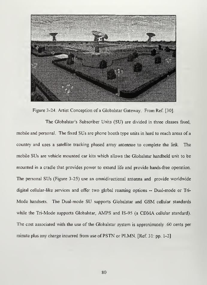
Figure 3-24. Artist Conception of a Globalstar Gateway. From Ref. [30].
The Globalstar's Subscriber Units (SU) are divided in three classes fixed,
mobile and personal. The fixed SUs are phone booth type units in hard to reach areas of a
country and uses a satellite tracking phased array antennae to complete the link. The
mobile SUs are vehicle mounted car kits which allows the Globalstar handheld unit to be
mounted in a cradle that provides power to extend life and provide hands-fi*ee operation.
The personal SUs (Figure 3-25) use an omnidirectional antenna and provide worldwide
digital cellular-like services and offer two global roaming options ~ Dual-mode or Tri-
Mode handsets. The Dual-mode SU supports Globalstar and GSM cellular standards
while the Tri-Mode supports Globalstar, AMPS and IS-95 (a CDMA cellular standard).
The cost associated with the use of the Globalstar system is approximately .60 cents per
minute plus any charge incurred fi-om use ofPSTN or PLMN. [Ref 31: pp. 1-2]
80

Figure 3-25. Globalstar's Personal Subscriber Units. From Ref. [31].
All three SU classes' capabilities revolve around Qualcomm's revolutionary
CDMA vocoder design. Qualcomm's vocoder takes advantage of the fact that in a typical
full duplex two-way voice conversation the average duty cycle of each voice is typically
only 35% to 40%. With the CDMA system, the transmitted data rate is reduced when
there is less speech activity allowing a corresponding reduction in transmitter power and
therefore a substantial reduction in interference to others. Decrease the interference you
can increase capacity by a factor of two or more and the energy efficiency by a factor of
three. TDMA and FDMA can not produce these results because each signal operates in a
separate time slot or frequency channel. Qualcomm's vocoder design uses a 20 msec
frame interval and produces four different data rates which can vary every 20 msec frame.
The terrestrial rates are 9600, 4800, 2400 and 1200 bits per second (actual data
transmission is slightly lower because of overhead bits). The vocoder rate will vary each
81

frame in response to voice/data activity. When no activity is detected, the rate drops to
1200 bps. The CDMA system automatically reduces transmission power when lower rate
vocoder frames are produced. This reduces average interference to others and allows
proportionately higher capacity. [Ref. 32: pp. 14]
Globalstar's basic operations have been discussed previously and depicted
in Figure 3-18 without actually discussing how Globalstar registers, authenticates and bills
its users. Globalstar uses CDMA bilateration which is cooperative ranging between the
SU and the Gateway. This is accomplished by a one time or sequential round-trip
transmissions with an accuracy of 10 km for caller assignment and 300 m for billable
services. The user position is not stored within the system. The registration and
authentication procedures is described in Figure 3-26.
rp) Subcriber Turns on hand set. Registration request sent to Gateway with ID.
(2) Gateway Checks ID list to check, if active. If YES, wait for call or page otherwise:
(3) Signalling message sent to subscriber's home network to request user profile and authentication.
(4) HLR requests random challenge data from AuC.
(£) AuC provides requeSsted data.
{£) HLR passes random challenge data and user profile back to Gateway.
k2) Gateway forwards the random challenge (RAND) to the handset and compares its responses with the
expected authentication signature to verify handset's authenticity.
Vuthenticatio
Center
n Home Location
Registar
1
©^ ^
AuC HLR Gateway
© ©(Existing) (Existing) ©
Figure 3-26. Globalstar's Registration and Authentication Procedure. After Ref [27].
82

Globalstar's billing procedure is demonstrated in Figure 3-27. [Ref. 27: pp. 11-12]
•When a call is tenninated, standard protocols will be used to determine satellite air time at the
gateway (.60 cents per minute).
•Accounting for the terrestrial portion of the call will be established by the carrer (?$).
•A single consolidated bill statement will be sent by the Globalstar Service Provider to the Globalstar
user.
I
Y
Wireline
Wireless
Provider<. — . — Globalstar
Gateway
S Satellite Portion
$ Terrestrial
Portion
iGlobalsta
Service
Provider
'^ Consolidated
Billing
Figure 3-27. Globalstar's Billing Procedure. After Ref. [27].
2. System Strengths
Globalstar's strengths are their handsets (cost, portability, multiple modes and
vocoder), CDMA signal, geolocation, proven satellite technology, path diversity and low
usage costs. Globalstar's handsets are even less expensive than Iridium's handsets. Priced
around $700.00, the low cost would enable spare sets to be bought as ready replacements.
The cellular phone size and weight of a Globalstar handsets provides the user with
unlimited mobility allowing them to be used in most parts of the world (on land between
70°N to 70° S latitudes). The multiple mode options available with Globalstar's handsets
83

allow access to any terrestrial cellular phone system enhancing the systems overall
flexibility. The vocoder ability to produce four different rates every 20 msec to
compensate for low usage reduces transmission power which would increase battery life,
produce a less detectable signal and increase overall system capacity. [Ref 33: pp. 3-4]
CDMA, as discussed in previous sections, provides many benefits. CDMA
provides spectrum-efficient, economical and high quality signals. CDMA signals are
harder to detect as they use a psuedorandom number (PN) to encode the signal which is
spread throughout the allotted frequency spectrum (Figure 3-6). Even when detected, the
entity bent on exploitation of a CDMA signal would have to break the PN code first.
Jamming a CDMA signal is also more diflficuh to accomplish as the CDMA signal is
spread over an entire frequency channel. Finally, CDMA allows for multiple path
diversity. [Ref 33: pp. 4-5]
Geolocation, which is built into Globalstar, can provide a useful service to Navy
users. The geolocation will be accurate to 300 meters for billing purposes. At that level of
accuracy, the Navy could develop uses for the system such as geolocating and monitoring
friendly forces. [Ref 33: pp. 6]
Globalstar satellite technology is well proven. All the subsystems have been
successfully employed on previous satellites. The bent pipe transponder system has
proven to be highly reliable and efficient. Finally, the phased array antennas are
electronically steerable eliminating the need for mechanical steering of antenna removes
84

potential mechanical failures and is much less demanding on the attitude control system.
[Ref. 27: pp. 12]
Globalstar provides path diversity by using CDMA, using a rake receiver and
providing several satellites in view of one mobile terminal at one time. Globalstar provides
the user the opportunity to transmit and receive by way of the satellite with the best
available signal, or to (rake receiver) combine all available signals to produce an even
better signal. In situations where a particular user-satellite path may be blocked by a
structure or foliage, Globalstar's path diversity will provide the user access to a second or
third satellite in view. This diversity scheme will achieve a high degree of circuit
availability and will allow each mobile user terminal to operate at a lower power level
Figure 3-28 demonstrates the concept of path diversity. [Ref 33: pp. 5-6]
Globalstar Gateway
Decoder
and *
Vocoder
Combiner
Receiver 1
RfOf'ivpr ."?
Building or
Other
Obstruction
Figure 3-28. Globalstar's Path Diversity. After Ref [27].
85

Globalstar's low cost of .60 cents per minute is very attractive especially when
considering using Globalstar as major part of a regional network. If netted
communications are possible, Globalstar looks extremely affordable. Table 3-14 presents a
sample scenario for using Globalstar in a netted mode, assuming one network and varying
the number of users from 2-10 for a 24 hour operation.
Number of
Users
''''""'''"OoiMn'"''''"^'^'''''^" Number of
Hours
Total Cost
2 .6 24 $1,728.00
4 .6 24 $3,456.00
6 .6 24 $5,184.00
8 .6 24 $6,912.00
10 .6 24 $8,640.00
Table 3-14. Example of Globalstar Costs for Netted Communications.
Even when considering that in a theater of operations you would have potentially
hundreds of networks which would have to be established, the Globalstar's cost for netted
communications still looks attractive. For a 30 day operation with only 100 networks, a
limit of 10 per network operating 24 hours a day, a total cost of $259,200.00.
Significantly better than the $129,600,000.00 it would cost to run the same operation with
Iridium.
3. System Weaknesses
In addition to the standard commercial weaknesses shared by all commercial
systems— assured access and system vulnerabilities, Globalstar major weakness is its
inability to provide truly worldwide access. The system supports a total of 130,368 full
86
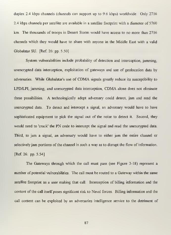
duplex 2.4 kbps channels (channels can support up to 9.6 kbps) worldwide. Only 2716
2.4 kbps channels per satellite are available in a satellite footprint with a diameter of 5760
km. The thousands of troops in Desert Storm would have access to no more than 2716
channels which they would have to share with anyone in the Middle East with a valid
Globalstar SU. [Ref 26: pp. 5.50]
System vulnerabilities include probability of detection and interception, jamming,
unencrypted data interception, exploitation of gateways and use of geolocation data by
adversaries. While Globalstar's use of CDMA signals greatly reduce its susceptibility to
LPD/LPI, jamming, and unencrypted data interception, CDMA alone does not eliminate
these possibilities. A technologically adept adversary could detect, jam and read the
unencrypted data. To detect and intercept a signal, an adversary would have to have
sophisticated equipment to pick the signal out of the noise to detect it. Second, they
would need to 'crack' the PN code to intercept the signal and read the unencrypted data.
Third, to jam a signal, an adversary would have to either jam the entire channel or
selectively jam portions of the channel in such a way as to disrupt the flow of information.
[Ref 26: pp. 5.54]
The Gateways through which the call must pass (see Figure 3-18) represent a
number of potential vulnerabilities. The call must be routed to a Gateway within the same
satellite footprint as a user making that call. Interception of billing information and the
content of the call itself poses significant risk to Naval forces. Billing information and the
call content can be exploited by an adversaries intelligence service to the detriment of
87

Naval operations. The geolocation data, which could also be intercepted at the local
Gateway, could be used to target Naval forces. Control of any of the nodes or links of the
registration and authentication process could be used by an adversary to prevent
connection by a valid user by falsifying or corrupting call setup data. [Ref 26: pp. 5.57]
Globalstar's greatest weakness is the coverage it provides. With an inclination of
52°, Globalstar can provide no (or extremely limited) polar coverage. Globalstar's
coverage of the rest of the world between 70°N and 70° S latitudes is confined to to areas
with terrestrial gateways. In general, that limits Globalstar to land masses with limited
ocean coverage (littoral areas). Globalstar has no onboard processing or crosslink
capabilities. In order to use a Globalstar SU, a SU and a Gateway must be within the
same satellite footprint. If there is no Gateway in the Globalstar satellite footprint of a
Globalstar user, the user would have better luck communicating with smoke signals
because Globalstar won't be able to provide a connection.
88

IV. INTEGRATION OF COMMERCIAL MOBILE SATELLITE SERVICESINTO NAVAL COMMUNICATIONS
A. MSS POTENTIAL NAVAL COMMUNICATIONS MISSIONS
Potential naval communications MSS missions considered are narrowband
communications <64 kbps on the move. These missions are based on the DoD
Communications FRD and discussions with DoDAJSN personnel as described in
preceding sections. Inmarsat provides mobile communications services, up to 64 kbps, to
ships at sea while Globalstar and Iridium provide personnel communication services, at 2.4
to 4.8 kbps, to a mobile individual. The 12 Naval/DoD missions are:
Polar Communications
VTP/Flag Communications
GBS Orderwire Communications
Combat Search and Rescue Communications
Command and Control of Tactical Forces Communications
Maritime Operations Command Communications
Special Operations Communications
Naval Surface Fire Support (NSFS) Ship-to-Shore Communications
Logistics Support Communications
Morale Support Communications
Peacekeeping and Humanitarian Operations Communications
Military Support to Civilian Authorities Communications
Each mission listed above will be discussed in greater detail in the subsequent
sections. A brief description will be made and the mission requirements, defined in Table
4-1, provided. The minimum and the optimum requirement will be provided. [Ref 34: pp.
F.l -F.2]
89

Mission Requirement Definition
Communications Services Voice, Data, Fax (rates) and DISN access (Yes/No)
Area of Operation (Latitudes which must have coverage or Global)
Platforms (Aircraft, Ships, Submarine, Vehicular and/or Ground)
Security Confidentiality (SI, Top Secret, Secret or None), Anti-Jam
(High, Med, Low or None), LPI/LPD (High, Med, Low or
None).
Operations Service Density (High, Med or Low), Assured Access
(High, Med, Low or None), Priority Calling (Yes or No)
1.
Table 4-1. MSS Mission Requirements Defined.
Polar Communications
Polar Communications are those communications Unking deployed forces
operating between 65°N to 90°N with the DIL Examples of Polar Communications
include SSN in the polar region providing status reports, medical emergency requests or
Tomahawk Mission Data Update (MDU). Polar Communications mission requirements
are summarized in Table 4-2. [Ref 34:pp.F.2-F.3]
90

Mission Requirements Minimum Optimum
Communications Services
Voice 2400 bps 2400 bps
Data 2400 bps 2400 bps
Fax 2400 bps 2400 bps
DISN Access No NoArea of Operation 65°N to 90°N 65°N to 90°N
Platforms Aircraft, Ships, Submarines, Aircraft, Ships, Submarines,
Ground Ground
Security
Confidentiality Secret Top Secret
Anti-Jam High High
LPI/LPD High High
Operations
Service Density Low LowAssured Access Med NonePriority Calling No Yes
Table 4-2. Polar Communications Mission Requirements. After Ref. [34]
2. VIP/Flag Communications
The VTP/Flag Communications are those communications which provide Flag
Officers and VIPs the ability to communicate effectively while on travel. An example of
this mission is how CINCPAC would need to remain up to date as she travels from
California to South Korea in response to escalating tensions in the area. VIP/Flag
Communications mission requirements are depicted in Table 4-3. [Ref 34: pp. F.3 - F.4].
91

Mission Requirements Minimum Optimum
Communications Services
Voice 2400 bps (voice recognition) 4800 bps
Data 4800 bps 9600 bps
Fax 4800 bps 9600 bps
DISN Access Yes Yes
Area of Operation 70°N to 70°S Global
Platforms Aircraft, Ships, Veliicular, Aircraft, Ships,
Ground Vehicular, Ground
Security
Confldentiality Secret Top Secret
Anti-Jam High High
LPI/LPD None LowOperations
Service Density Low LowAssured Access High High
Priority Calling No Yes
Table 4-3. VTP/Flag Communications Mission Requirements. After Ref. [34]
3. GBS Orderwire Communications
The Global Broadcast Service (GBS) will provide high capacity broadcast
capability to support the timely dissemination of high capacity information products
worldwide (70°N to 70°S). GBS Orderwire Communications are those communications
which would allow deployed forces to access the source of the information products to
allow a user to tailor information requirements for delivery via GBS. An example of this
mission is an artillery officer who calls back to GBS operators requesting updated battle
damage assessment photos be sent via GBS broadcast. GBS Orderwire Communications
mission requirements are depicted in Table 4-4. [Ref 34: pp. F.4 - F.5]
92

Mission Requirements Minimum Optimum
Communications Services
Voice 2400 bps 2400 bps
Data 4800 bps 4800 bps
Fax No NoDISN Access No Yes
Area of Operation 70°N to 70°S 70°N to 70° S
Platforms Aircraft, Ships, Vehicular, Aircraft, Ships, Vehicular,
Ground Ground
Security
Confidentiality Secret Top Secret
Anti-Jam None LowLPI/LPD None Low
Operations
Service Density Low LowAssured Access Med High
Priority Calling No Yes
Table 4-4. GBS Orderwire Communications Mission Requirements. After Ref. [34]
4. Combat Search and Rescue (CSAR) Communications
DoD requirements ft^r CSAR radio include that it provide highly accurate position
inft)rmation, over the horizon data communications, and line of sight voice
communications. In addition, it must be a small ruggedized hand-held unit able to survive
salt water immersion, aircrew ejection and support editable, canned data messages. An
example of this mission is a downed pilot who edits and sends a reformatted message
providing his precise status and location using integrated GPS receiver. CSAR
Communications mission requirements are depicted in Table 4-5. [Ref. 34: pp. F.5 - F.6]
93

Mission Requirements Minimum OptimumCommunications Services
Voice
Data
Fax
DISN Access
2400 bps
2400 bps
NoNo
2400 bps
4800 bps
NoNo
Area of Operation 70°N to 70°S Global
Platforms Ground Ground
Security
Confidentiality
Anti-Jam
LPI/LPD
NoneHigh
High
NoneHigh
High
Operations
Service Density
Assured Access
Priority Calling
LowHigh
Yes
LowHigh
Yes
Table 4-5. CSAR Communications Mission Requirements. After Ref. [34]
5. Command and Control (C2) of Tactical Forces Communications
C2 of Tactical Forces Communications is for providing connectivity both between
high level commanders and highly mobile tactical forces. This mission's main importance
lies in providing a surge capacity during the initial entry into a region before standard
telecommunications services can be established. For example, a Joint Task Force entry
team would need voice and data services immediately to coordinate the build-up of forces
in a particular area of interest. C2 of Tactical Forces Communications mission
requirements are depicted in Table 4-6. [Ref 34: pp. F. 6 - F. 7]
94
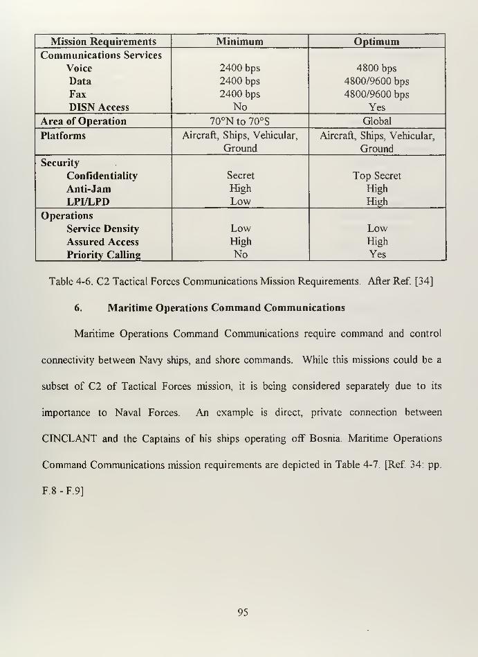
Mission Requirements Minimum OptimumCommunications Services
Voice 2400 bps 4800 bps
Data 2400 bps 4800/9600 bps
Fax 2400 bps 4800/9600 bps
DISN Access No Yes
Area of Operation 70°N to 70° S Global
Platforms Aircraft, Ships, Vehicular, Aircraft, Ships, Vehicular,
Ground Ground
Security
Confidentiality Secret Top Secret
Anti-Jam High High
LPI/LPD Low High
Operations
Service Density Low LowAssured Access High High
Priority Calling No Yes
Table 4-6. C2 Tactical Forces Communications Mission Requirements. After Ref. [34]
6. Maritime Operations Command Communications
Maritime Operations Command Communications require command and control
connectivity between Navy ships, and shore commands. While this missions could be a
subset of C2 of Tactical Forces mission, it is being considered separately due to its
importance to Naval Forces. An example is direct, private connection between
CINCLANT and the Captains of his ships operating off Bosnia. Maritime Operations
Command Communications mission requirements are depicted in Table 4-7. [Ref 34: pp.
F.8-F.9]
95

Mission Requirements Minimum Optimum
Communications Services
Voice
Data
Fax
DISN Access
2400 bps
2400 bps
2400
Yes
4800 bps
56 kbps*
4800 bps
Yes
Area of Operation 70°N to 70°S Global
Platforms Ships, Submarines Ships, Submarines
Security
Confidentiality
Anti-Jam
LPL1.PD
Secret
High
None
Top Secret
High
High
Operations
Service Density
Assured Access
Priority Calling
LowHigh
No
LowHigh
Yes
*Note: Requirement to Connect to the Global Command and Control System.
Table 4-7. Maritime Operations Command Communications. After Ref. [34]
7. Special Operations Communications
Special Operations Communications missions would provide for cormectivity to
deployed special forces units. The desire is to provide higher level commanders
connectivity to their highly mobile special forces units. An example is a special forces
team deployed in a foreign country calling their commander to confirm their operation is a
go. Special Operations Communications mission requirements are depicted in Table 4-8.
[Ref. 34:pp. F9-F.10]
96
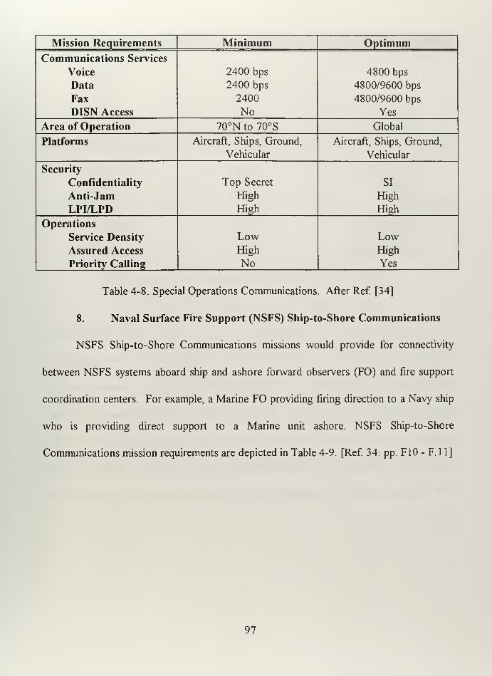
Mission Requirements Minimum Optimum
Communications Services
Voice
Data
Fax
DISN Access
2400 bps
2400 bps
2400
No
4800 bps
4800/9600 bps
4800/9600 bps
Yes
Area of Operation 70°N to 70° S Global
Platforms Aircraft, Ships, Ground,
Vehicular
Aircraft, Ships, Ground,
Vehicular
Security
Confidentiality
Anti-Jam
LPI/LPD
Top Secret
High
High
SI
High
High
Operations
Service Density
Assured Access
Priority Calling
LowHigh
No
LowHigh
Yes
Table 4-8. Special Operations Communications. After Ref. [34]
8. Naval Surface Fire Support (NSFS) Ship-to-Shore Communications
NSFS Ship-to-Shore Communications missions would provide for connectivity
between NSFS systems aboard ship and ashore forward observers (FO) and fire support
coordination centers. For example, a Marine FO providing firing direction to a Navy ship
who is providing direct support to a Marine unit ashore. NSFS Ship-to-Shore
Communications mission requirements are depicted in Table 4-9. [Ref. 34: pp. FIO - F. 11]
97

Mission Requirements Minimum Optimum
Communications Services
Voice 2400 bps 2400 bps
Data 4800 bps 9600 bps
Fax No NoDISN Access No Yes
Area of Operation 70°N to 70°S Global
Platforms Ships, Ground, Vehicular Ships, Ground, Vehicular
Security
Confidentiality None Secret
Anti-Jam High High
LPI/LPD Low High
Operations
Service Density High High
Assured Access High High
Priority Calling No Yes
Table 4-9. NSFS Ship-to-Shore Communications. After Ref. [34]
9. Logistics Support Communications
Logistics Support Communications missions provide connectivity between
logistics commands and the logistics personnel of deployed forces and perhaps an
automated cargo tracking system. This service would provide for transfer of logistics
reports, tracking of items in transit, manual transfers and maintenance information
transfer. An example might be a forward deployed unit running low on ammunition could
query a U.S. based logistics command for status of next shipment. Logistics Support
Communications mission requirements are depicted in Table 4-10. [Ref 34: pp. Fll -
F.12]
98

Mission Requirements Minimum Optimum
Communications Services
Voice 2400 bps 4800 bps
Data 2400 bps 4800/9600 bps
Fax No Yes
DISN Access No Yes
Area of Operation 70°N to 70°S Global
Platforms Ships, Ground, Vehicular Ships, Ground, Vehicular
Security
Confidentiality None Secret
Anti-Jam None LowLPI/LPD None Low
Operations
Service Density Low LowAssured Access Med High
Priority Calling No No
Table 4-10. Logistics Support Communications. After Ref. [34]
10. Morale Support Communications
Morale Support Communications missions allow PSTN calls through the DISN
from remote locations around the world. This mission allows remotely located personnel
to phone home thereby enhancing unit morale. The capability would be provided by the
unit with the unit personnel calling home at their own expense. For example, personnel
stationed upon a FFG in the middle of the Pacific could place calls home to family
members. Morale Support Communications mission requirements are depicted in Table 4-
11. [Ref 34:pp. F12-F.13]
99

Mission Requirements Minimum Optimum
Communications Services
Voice
Data
Fax
DISN Access
2400 bps
2400 bps
2400 bps
Yes
4800 bps
4800 bps
4800 bps
Yes
Area of Operation 70°Nto70°S Global
Platforms Ships, Ground Ships, Ground
Security
Confidentiality
Anti-Jam
LPI/LPD
NoneNoneNone
NoneNoneLow
Operations
Service Density
Assured Access
Priority Calling
LowLowNo
LowLowNo
Table 4-11. Morale Support Communications. After Ref. [34]
11. Peace Keeping and Humanitarian Operations Communications
Peace Keeping and Humanitarian Operations Communications mission requires
connectivity of national and international tactical forces deployed in support of
peacekeeping or humanitarian missions. For example, UN forces operating in Bosnia
separated by mountains which prevent LOS communications. Peace Keeping and
Humanitarian Operations Communications mission requirements are depicted in Table 4-
12. [Ref 34:pp. F13-F.14]
100

Mission Requirements Minimum Optimum
Communications Services
Voice
Data
Fax
DISN Access
2400 bps
2400 bps
2400 bps
Yes
4800 bps
4800 bps
4800 bps
Yes
Area of Operation 70°N to 70° S 70°N to 70°S
Platforms Aircraft, Ships, Ground,
Vehicular
Aircraft, Ships, Ground,
Vehicular
Security
Confidentiality
Anti-Jam
LPI/LPD
Secret
LowNone
Secret
LowLow
Operations
Service Density
Assured Access
Priority Calling
LowHigh
No
High
High
Yes
Table 4-12. Peace Keeping and Humanitarian Operations. After Ref. [34]
12. Military Support to Civilian Authorities Communications
Military Support to Civilian Authorities Communications mission requires
connectivity between the military forces and civilian authorities such as FEMA, FBI, Coast
Guard or DEA. An example is the coordination necessary between the Navy, Coast
Guard and DEA agents in the apprehension of a drug runner on the high seas Military
Support to Civilian Authorities Communications mission requirements are depicted in
Table 4-13. [Ref 34: pp. F13-F. 14]
101

Mission Requirements Minimum Optimum
Communications Services
Voice 2400 bps 4800 bps
Data 4800 bps 9600 bps
Fax 4800 bps 9600 bps
DISN Access Yes Yes
Area of Operation 70°N to 70°S 70°N to 70°S
Platforms Aircraft, Ships, Ground, Aircraft, Ships, Ground,
Vehicular Vehicular
Security
Confidentiality None Secret
Anti-Jam Low LowLPI/LPD None High
Operations
Service Density Low High
Assured Access High High
Priority Calling Yes Yes
B.
Table 4-13. Military Support to Civilian Authorities. After Ref. [34]
POTENTIAL DOD ENHANCEMENTS TO COMMERCL^L MOBILESATELLITE SERVICES
1. Inmarsat
DoD enhancements to Inmarsat include using existing encryption devices, leasing
transponders and centralizing control. The Navy is currently using STU III encryption
devices for 9.6 kbps communications and KG-84's for up to 64 kbps data rate encryption.
Communications terminals which utilize these encryption devices are approved by the
National Security Agency (NSA) to transmit Top Secret SI level communications. They
all but assure that, when used properly, these devices will render the communications
unreadable even to the most sophisticated adversary.
102

Leasing Inmarsat satellite transponders will cost the Navy less and increase Navy
control. The Navy spent over $3,000,000.00 dollars in 1995 on Inmarsat calls with only
125 ships with Inmarsat capability. The Navy will have 250 ships Inmarsat capable by the
end of 1997 and will be relying even more on Inmarsat communications capabilities. For
the same cost in 1995 the Navy could have leased transponders on each of the Inmarsat
satellites worldwide. A leased transponder would enable the Navy to provide assured
access, prioritize calls and control costs. No high priority caller would have to get a busy
signal from an overtaxed satellite. The Navy could prioritize its users and bump who they
needed to make room for the higher priority. The bumped individual could wait for access
to the Navy's transponder or choose to use the pay-as-you-go standard Inmarsat service.
[Ref 35]
Centralized control of Navy Inmarsat services would allow for greater flexibility
and cost savings. Statistics could be compiled which would provide a basis for studying
usage patterns and lead to increasing Inmarsat's utility to the Navy. A central Naval
control would facilitate Navy wide broadcasts, setting up connections with other DoD
agencies and provide a single connection point for GCCS. Netted communications would
be possible as the Navy would own the transponder and with centralized control could set
up communications nets with a portion of each transponders allotted bandwidth. A cost
savings would be had by reducing the overhead that is necessary to maintain a more
decentralized control system. Additionally, centralized billing, as opposed to each unit
103

paying for Inmarsat services, would decrease COMSAT'S administrative costs which
would be reflected as lower service charges to the Navy. [Ref 35]
The enhancements discussed above along with an increase in operational diligence
greatly increase Inmarsat's utility to the Navy. Table 4-14 compares Inmarsat with the
DoD-enhanced Inmarsat using the required capabilities identified by the MUS WIPT
discussed earlier.
Required Capabilities Inmarsat DoD-enhanced
Inmarsat
Assured Access Red Grn
Netted Comms Red Grn
Comms On the Move Ylw Ylw
Joint Interoperable Ylw Ylw
World Wide Coverage Gm GmPoint to Point Comms Gm Gm
Broadcast Gm GmPolar Red Red
2.
Table 4-14. Inmarsat versus DoD-enhanced Inmarsat. After Ref [7]
Iridium
DoD potential enhancements to Iridium include a secret key system, NSA
developed STU III encryption capability, specializing terminals, a single government
owned and operated gateway and contracting additional services. Iridium has
incorporated features to prevent fraudulent use of the system like "cloning a cellular
phone". To accomplish this, the users unique number is never transmitted. The user is
assigned a new temporary ID to use on at least a daily basis. The phone number of the
user does not change. The gateway stores the temporary ID for each user. An
104

authentication process using a secret key and cryptographic algorithm is performed prior
to the call set up. The secret key is virtually impossible to break as the algorithm uses a
64 bit random challenge, 32 bit signed response and finally, a 128 bit secret key. [Ref. 36:
pp. 13 14]
Condor is a NSA sponsored program intent on providing modular security to
mobile phones including rnobile satellite service phones. Condor will provide a sleeve
which will attach to the back of Iridium's cellular handset with the battery attaching to the
back of the sleeve. The sleeve will accommodate a cryptographic PCMCIA card which
will provide STU-III capable communications. When connected to the Iridium handset,
Condor will create a trusted handset capable of communicating securely anywhere in the
world. [Ref 37]
The terminals provided by Iridium will fit most missions. However, ruggedized
terminals will have to be developed for shipboard use and field use. Shipboard use, to
include CSAR missions, will require ruggedized and specialized terminals. To operate in a
ship environment, the terminals will have to be able to be salt water resistant. To be of
use for CSAR mission, the terminals will have to be salt water proof and shock resistant.
Similar requirements will be necessary for operating under the physically stressfiil
environment of military operations ashore. Shore terminals will have to be weather and
shock resistance. Finally, GPS like capabilities can be incorporated into certain terminals
such as remote sensor terminals and CSAR terminals to assist in providing position
105

location data. DoD has extensive experience in ruggedizing and specializing commercial
equipment to meet its own unique needs making these requirements imminently attainable.
A single government owned and operated gateway greatly increases Iridium's
utility for Navy and DoD operations. As discussed in Chapter Three, a commercial
Iridium call's information passes through numerous foreign gateways which pose
significant security risks to DoD users. By using a government gateway, foreign
involvement in a DoD call can be eliminated. The government gateway would function as
the home, visiting and distribution gateway. No foreign government need ever see DoD
access requests, signaling information or billing information. Government users must use
the government gateway which will provide a number of additional utilities. Control of
DoD caller access and priority schemes can be established. DoD callers could be
prioritized according to the needs and desires of the regional commander and the
government gateway managers would be able to implement that plan among the callers
under their control. Pseudo netted communications could be enabled by combining calls
at the gateway in a way similar to conference calling. Direct interface into the DISN along
with the ability to originate calls from the gateway to an Iridium user will increase
Iridium's Joint Interoperable capabilities. Finally, consolidation in billing will significantly
reduce costs. [Ref 38]
Additional services which can be contracted fi"om Iridium are priority preference,
guaranteed call access and a surge provision. The government gateway can only prioritize
DoD calls. Furthermore, the gateway can only provide assured access among DoD users;
106

meaning they cannot remove callers other than DoD callers to make room for a higher
priority caller. If a satellite is busy, subsequent calls made to said satellite are queued in a
first come first serve basis. DoD could pay for the privilege of going to the top of the
queue when a satellite is busy and obtaining the next available circuit. DoD could also pay
for a number of circuits on each satellite to be reserved exclusively for DoD use. For
example, a satellite over a particular hot spot is overwhelmed by commercial users, but
with the guaranteed access clause, DoD would still have a number of circuits available for
its exclusive use. Finally, CNN and other commercial information entities pay
communications satellite companies a contingency fee for the privilege of being able to up
their demand upon a moments notice. DoD could work out similar terms. DoD could pay
a contingency fee for the ability to increase the number of guaranteed circuits over a
particular hot spot during a crisis. This ability would increase DoD's surge capacity and
greatly increase Iridium's utility during times of crisis.
The enhancements discussed above in conjunction with Iridium's truly world wide
coverage would greatly increase Iridium's utility to the Navy. Table 4-15 compares
Iridium with the DoD-enhanced Iridium using the required capabilities identified by the
MUS WIPT discussed earlier.
107

Required Capabilities Iridium DoD-enhanced
Iridium
Assured Access Red GrnNetted Coraras Red Ylw
Comms On the Move Grn Grn
Joint Interoperable Ylw GrnWorld Wide Coverage Grn GmPoint to Point Comms Grn Grn
Broadcast Ylw Ylw
Polar Grn Gm
Table 4-15. Iridium versus DoD-enhanced Iridium. After Ref. [7]
3. Globalstar
DoD potential enhancements to Globalstar include a NSA developed STU III
encryption capability, specialized terminals, government worldwide fixed and transportable
gateways, group services and contracting additional services. Condor is a NSA sponsored
program intent on providing modular security to mobile phones including mobile satellite
service phones. Condor will provide a sleeve which will attach to the back of Globalstar'
s
cellular handset with the battery attaching to the back of the sleeve. The sleeve will
accommodate a cryptographic PCMCIA card which will provide STU-III capable
communications. When connected to the Globalstar handset. Condor will create a trusted
handset capable of communicating securely anywhere in the world. [Ref 37]
The terminals provided by Globalstar will fit most missions. However, ruggedized
terminals will have to be developed for shipboard use and field use. Shipboard use, to
include CSAR missions, will require ruggedized and specialized terminals. To operate in a
ship environment, the terminals will have to be able to be salt water resistant. To be of
108

use for CSAR mission, the terminals will have to be salt water proof and shock resistant.
Similar requirements will be necessary for operating under the physically stressful
environment of military operations ashore. Shore terminals will have to be weather and
shock resistance. Finally, GPS like capabilities can be incorporated into certain terminals
such as remote sensor terminals and CSAR terminals to assist in providing position
location data. DoD has extensive experience in ruggedizing and specializing commercial
equipment to meet its own unique needs making these requirements imminently attainable.
Globalstar's shortcomings in regard to world wide coverage and foreign gateway
interaction with DoD calls was discussed in Chapter III. One proposal to greatly increase
world wide coverage while decreasing dependence on foreign gateways for DoD calls is a
combination of fixed and transportable DoD gateways. The fixed gateways would be
placed strategically around the world to minimize coverage gaps specifically over the open
ocean and higher latitudes. Transportable DoD gateways could be flown into any AOR to
establish a DoD only gateway eliminating the need to use a foreign gateway during a
sensitive operation. Control of these gateways provide many of the same benefits
mentioned above in the section on Iridium ~ control of DoD caller access, information,
establishing priority schemes and increasing joint interoperability. [Ref 39]
Group services, which can be provided by Globalstar, will enable broadcast and
networking capabilities. Work group services work on a defined group of services and
provide for one talker with many listeners. The system allocates broadcast channels
dynamically based on the users. A single phone number activates the service which can
109

operate within the Globalstar system or a terrestrial system. Group services are five to
twenty times more efficient than normal telephone conferencing. Services provided are
voice, data, multiple work groups, text messaging, voice mail and security. Features
include push-to-talk ,for netted communications on demand, selection of security modes,
and system notifications on who's talking, workgroups active, conventional calls, voice
mail availability, text messaging and paging/alerting functions. [Ref 40]
Additional services which can be contracted from Globalstar are priority
preference, guaranteed call access and a surge provision. A government gateway can
only prioritize DoD calls. Furthermore, a gateway can only provide assured access among
DoD users. Meaning they cannot remove callers other than DoD callers to make room for
a higher priority caller. If a satellite is busy, subsequent calls made to said satellite are
queued in a first come first serve basis. DoD could pay for the privilege of going to the
top of the queue when a satellite is busy and obtaining the next available circuit. DoD
could also pay for a number of circuits on each satellite to be exclusively reserved for DoD
use. For example, a satellite over a particular hot spot is overwhelmed by commercial
users, but with the guaranteed access clause, DoD would still have a number of circuits
available for its exclusive use. Finally, CNN and other commercial information entities
pay communications satellite companies a contingency fee for the privilege of being able
to up their demand upon a moments notice. DoD could work out similar terms. DoD
could pay a contingency fee for the ability to increase the number of guaranteed circuits
110

over a particular hot spot during a crisis. This ability would increase DoD's surge
capacity and greatly increase Globalstar's utility during times of crisis.
DoD-enhanced Globalstar MSS would have significant impact on the manner in
which Naval forces communicate. Table 4-16 compares Globalstar with the DoD-
enhanced Globalstar using the required capabilities identified by the MUS WIPT discussed
earlier.
Required Capabilities Globalstar DoD-enhanced
Globalstar
Assured Access Ylw Ylw/Grn
Netted Comms Ylw GrnComms On the Move Gm Grn
Joint Interoperable Ylw GrnWorld wide Coverage Ylw Ylw/Grn
Point to Point Comms Gm GmBroadcast Ylw Grn
Polar Red Ylw
c.
Table 4-16. Globalstar versus DoD-enhanced Globalstar. After Ref [7]
DOD UHF SYSTEMS AND DOD-ENHANCED MSS ABILITY TOSATISFY DOD/NAVAL REQUIREMENTS
DoD UHF systems and DoD-enhanced Mobile Satellite Services (MSS) can be
compared against the DoD fiinctional requirements which where discussed in Chapter II.
These functional requirements are delineated below:
• Connectivity - The geographical coverage of the satellite
communications system in reference to the users of that system and the
capacity of the system relative to data throughput.
• Protection - The ability to avoid, prevent, negate, or mitigate the
degradation, disruption, denial, unauthorized access, or exploitation of
communications services by adversaries or the envirormient.
Ill

• Access and control - Access means immediate accessibility and
availability when needed. Control refers to the ability to effectively
plan, operate, manage and manipulate the available SATCOMresources.
• Interoperablity- The ability of varying forces to communicate with
one another quickly and effectively.
• Flexibility - The ability to support the full dynamic range of military
operations and missions.
• Quality of Service - The ability to transfer information in a timely and
accurate manner.
DoD UHF systems underachieve in the areas of geographical coverage (limited to 65° N
to 65° S latitudes), capacity (210 unfulfilled requirements described in Table 2-10),
protection (has all ofUHF vulnerabilities), interoperability (specialized service unique
terminals), flexibility (inability to support omnidirectional antennas limit utility man mobile
communications) and quality of service (over taxed systems impact adversely on quality).
DoD UHF systems provide much greater access and control as the systems are completely
under DoD control. DoD-enhanced MSS (Inmarsat, Iridium, and Globalstar), on the
other hand, provide marginal access and control as only a portion of the system and
certain user segments are under direct DoD control. Protection is another problem area
for DoD-enhanced systems. Although the communications can be secured using
encryption devices, UHF communications are inherently vulnerable to a skilled adversary.
Furthermore, the civil ownership of these systems increase the possibility of security
problems. DoD-enhanced MSS taken together do satisfy many of DoD/Naval functional
requirements. DoD-enhanced MSS provide greater coverage (with Iridium's worldwide
coverage), capacity (thousands of circuits versus hundreds for DoD UHF systems),
interoperability (with DoD owned gateways and connection into DISN), flexibility
112

(operational doctrine could be developed to cover full range of military operations and
missions) and finally, quality of service (MSS will push for ever higher quality of service to
support commercial interests as well as DoD). Table 4-17 uses a red (no satisfaction),
yellow (partial satisfaction) and green (full satisfaction) to compare DoD UHF systems
versus DoD-enhanced MSS.
DoD/Naval Functional
Requirements
DoD UHFSystems
DoD-EnhancedMSS
Connectivity Red/Yellow Yellow/Green
Protection Yellow Yellow
Access and Control Green Yellow
Interoperability RedA'ellow Yellow/Green
Flexibility Yellow Yellow/Green
Quality of Service Red/Yellow Yellow/Green
D.
Table 4-17. DoD UHF Systems Versus DoD-Enhanced MSS in Satisfying
DoD/Naval Functional Requirements.
INTEGRATION OF INMARSAT INTO NAVAL COMMUNICATIONS
Inmarsat is already well on its way to being completely integrated into Naval
Communications. As discussed in Chapter III, Inmarsat will be installed on every Naval
combatant afloat by the end on 1998. Due to its fixed-to-the-ship nature and inherent
vulnerabilities, Inmarsat main utility to Naval Communications will be in open water and
outer littoral regions of the world. Naval communications missions for which Inmarsat is
well-suited are C2 of Tactical Forces Communications, Maritime Command and Control
of Tactical Forces Communications, GBS Orderwire Communications, Logistics Support
Communications, Moral Support Communications, Peacekeeping and Humanitarian
113

Operations Communications and Military Support To Civilian Authorities
Communications. [Ref. 35]
Inmarsat is extremely well-suited for C2 of Tactical Forces Communications,
Maritime Command and Control of Tactical Forces Communications on the open ocean
and early entry into a region of instability. The Global Command and Control System
(GCCS) and Joint Maritime Command Information System (JMCIS) are the future of both
C2 and Maritime operations. Both require a relatively large two way pipe to operate
effectively. Inmarsat, with a capability of up to 64 kbps, meets GCCS and JMCIS
requirements which greatly increase its utility for use in C2 and Maritime Operations
communications.
GBS Orderwire, Logistical Support Communications and Moral Support
Communications can all be provided by Inmarsat simultaneously. By multiplexing a
number of 9.6 kbps links, a ship at sea can order a large image file from a GBS broadcast
provider, connect to logistical support in CONUS via a 9.6 kbps using SALTS program
and still have a number of pay-as-you-use phone calls to mom, providing moral support to
the troops.
Inmarsat was the first company to provide commercially available mobile
communications world wide. As such, many nations, organizations, government agencies,
and DoD entities purchased quite a few Inmarsat terminals. Having such a large and
varied install base currently makes Inmarsat a natural for Peacekeeping and Humanitarian
Operations Communications and Military Support To Civilian Authorities
114

Communications. In the near term, as many as 10,000 Inmarsat terminals as small as a
notebook computer have been sold world-wide, making the likelihood relatively high that
all parties concerned during a Peacekeeping, Joint or Interagency action will have access
to an Inmarsat terminal. Figure 4-1 depicts a number of Naval communications missions
for which DoD-enhanced Inmarsat appears well-suited.
INMARSATUFO/GBS
PSTN : Logistic,
MWR & Official
Phone calls.
GCCS:
Figure 4-1. Inmarsat Naval Communications Missions.
E. INTEGRATION OF IRIDIUM INTO NAVAL COMMUNICATIONS
Iridium will be used by DoD and the Navy in some capacity. Iridium as already
begun launching satellites and developing its infrastructure. DISA is actively pursuing
Iridium services. A site has been chosen and work begun on a DoD Iridium gateway.
NSA is producing, in cooperation with Iridium, a Condor sleeve to enable STU-III
115

capable handsets. Additional research is being done on netted services and contracting for
additional services. With DoD enhancements and world wide capabilities, Iridium will be
able to satisfy a number ofNaval communications missions. Naval missions which Iridium
is particularly well suited for include Polar Communications, VTP/Flag Communications,
GBS Orderwire Communications, Combat Search and Rescue Communications, Special
Operations Communications, Logistics Support Communications, Peacekeeping and
Humanitarian Operations Communications and Military Support to Civilian Authorities
Communications. [Ref 41]
Iridium is the only MSS under discussion which can cover the polar regions. As
such, Iridium can satisfy many of the polar communications requirements with some
additional modification. Naval forces which are operating in the North and South pole
research stations can use Iridium as is for communications which up to now have been
relegated to land lines and repeater stations. To provide services to Naval strategic forces,
additional research will need to be undertaken to develop LPI/LPD directional antenna
which will decrease the risk of geolocation of those assets. An Iridium tracking paraboUc
dish or phased array antenna would significantly reduce the likelihood of detection.
VIP/Flag Communications require a worldwide capability to support VIP/Flag
travel which can easily be accomplished using DoD-enhanced Iridium. With STU-III
capable communications and a DoD gateway, Iridium can provide secure links for
VTP/Flag travelers which would be extremely difficult for an adversary to exploit. By
using Iridium for a good portion of VTP/Flag travel communication, current tasking of
116

tactical MLLSATCOM assets could be significantly reduced fi-eeing them for tactical
forces.
GBS Orderwire could be satisfied by Iridium in all but the most strenuous
operational scenarios. Given Iridium's use ofTDMA/FDMA in the UHF frequency range,
Iridium should not be used in a tactical environment in which Naval forces could be
endangered by jamming or geolocation of their Iridium handsets. However, Naval forces
operate worldwide in numerous capacities. In those situations where the forces are safe
fi-om exploitation, Iridium could be used to order broadcast data to be delivered by GBS.
Combat Search and Rescue Communications (CSAR) can be accomplished using
Iridium with some additional DoD enhancements to the system. With its worldwide
capabilities, Iridium can provide an extremely valuable service by providing CSAR
services to the Navy's widely dispersed forces. Modifications which would enhance
Iridium's utility in CSAR include contracting guaranteed circuits, ruggedizing the handset,
integrating GPS and microburst communications. As discussed previously, a number of
circuits could be reserved for a cost worldwide ensuring a circuit would be available for
CSAR. Ruggedizing the handset would include salt waterproofing and providing shock
resistance capable of withstanding aircraft ejection. GPS has been integrated into
numerous applications and could be integrated into Iridium handsets to reduce Iridium's
geolocation capabilities from hundreds of meters to tens of meters. Finally, using existing
cellular digital messaging standards, microburst preformated messages could be used to
minimize the likelihood a CSAR communication could be located by an adversary.
117

Iridium cannot satisfy all of the Navy's Special Operations Communications needs
due to its use ofTDMA/FDMA. However, Iridium's worldwide capability combined with
the DoD-controlled gateway make it an attractive communications option for startup
actions or other initial covert operations. First, in an urban environment, differentiating an
Iridium phone from other cell phones would be next to impossible. Second, using
microburst communications, special operations Iridium communications would be difficuh
to geolocate. Finally, if the adversary is not expecting covert operations, short term
Iridium usage would more than likely go unnoticed.
Logistics Support Communications can be satisfied by Iridium in a number of
ways. The logistical software SALTS can be supported by the data rates provided by
Iridium to assist logisticians in making logistical requests. Iridium could also satisfy some
of the Strategic Airlift requirements by providing low data rate information to enhance
coordination of aircraft routing, passenger data, crew scheduling, etc. Finally, Iridium
friendly devices could send logistic shipment location data which could be used to track
supplies as they transit from CONUS to their final destination.
Iridium can become a cornerstone for Peacekeeping and Humanitarian Operations
Communications and Military Support to Civilian Authorities Communications. Given the
DoD controlled gateway. Iridium can provide secure and reliable communications which
will facilitate peacekeeping/humanitarian operations and military support to civilian
authorities. Iridium handsets could be issued for these missions to provide a standard
communications facility which will be inherently interoperable thereby greatly reducing the
118

communications planning and overhead. Figure 4-2 depicts a number of Naval
communications missions which DoD-enhanced Iridium appears to be well suited.
CJ-«sODDDoD Gateway
Figure 4-2. Iridium Naval Communications Missions.
F. INTEGRATION OF GLOBALSTAR INTO NAVAL COMMUNICATIONS
DoD-enhanced Globalstar possesses a number of characteristics which make it
extremely attractive for use by Naval forces. While Globalstar' s bent pipe characteristics
and lack of worldwide coverage limit its day to day usefulness, Globalstar' s use ofCDMA
and Group Services makes it particularly attractive for more extensive use by Naval
tactical forces. CDMA communications are inherently more difficult for an adversary to
exploit and Group Services allow tactical forces to operate in a networked mode. Naval
communications missions which Globalstar is particularly well suited for include GBS
119

Orderwire, Logistics Support Communications, C2 of Tactical Forces Communications,
Special Operations Communications, and NSFS Ship-to-Shore Communications. [Ref. 40]
Globalstar's CDMA communications signal would allow for GBS Orderwire and
Logistics Support Communications by tactical users in the field. An adversary would be
hard pressed to geolocate or interfere with these short requests by a Globalstar user for a
GBS broadcast tailored for their needs. With a tactical gateway deployed in theater, a
Globalstar user could request logistical assistance from the rear where the request could
be taken care of or relayed to a logistical support center out of theater.
C2 Tactical Forces Communications rely on networks for situational awareness
and to pass C2 information to units in the field. Globalstar's ability to provide a secure
communications path combined with Group Services allow the theater commander the
flexibility to establish Globalstar C2 nets as needed. In addition to networks provided by
Globalstar's Group Service, Globalstar's broadcast capabilities enable commanders to
push C2 information and guidance to units deployed in the field virtually eliminating the
possibility of individual unit detection. Finally, units could use Globalstar fiiendly devices
and random microburst transmissions of unit status information enhancing the tactical
commanders view of the battlefield.
Special Operations Communications involving incursions deep into adversarial
territory can be accomplished using Globalstar in conjunction with a Globalstar gateway
deployed in theater. Globalstar's CDMA communications makes detection and
geolocation difficult for all, but the most sophisticated adversary. Special operational
120

techniques such as microburst communications in conjunction with push broadcast
decrease an adversaries ability to disrupt communications even further. Globalstar's
additional ability to combine multiple signals from all satellites in view further enhance
Special Forces ability to operate in a wide range of areas from a cluttered urban
environment to a heavily forested region.
Naval forces using NSFS Ship-to-Shore Communications to direct Naval gun fire
can rely on Globalstar. Again, CDMA greatly reduces the possibility of detection while a
forward observer directs naval gun fire or calls for naval air support in support of tactical
operations ashore. Furthermore, Globalstar's ability to operate on the move in a cluttered
environment would allow the forward observer to communicate while remaining
concealed from view. Figure 4-2 depicts a number of Naval communications missions
which DoD-enhanced Globalstar appears to be well suited.
121

GLOBALSTAR UFO/GBS
Figure 4-3. Globalstar Naval Communications Missions.
122

V. CONCLUSIONS AND RECOMMENDATIONS
A. CONCLUSIONS
As discussed in Appendix A, DoD Satcom Systems cannot deliver enough UHF
services to support today's widely dispersed mobile forces information intensive needs.
By utilizing existing and soon-to-be-realized commercial MSS capabilities, information
flow to the Navy's highly mobile and dispersed forces can be greatly increased. By
capitalizing on each of the DoD-enhanced MSS strengths, DoD-enhanced MSS
communications can provide the missing mobile communications piece in the Naval
communications puzzle for the next five to ten years. Greater military control and
additional cost savings could be realized if the DoD developed a MSS-compatible in-
theater tactical arena mobile communications system (TAMCS). Given the inherent
vulnerabilities of commercial MSS and the cost of service, DoD should explore military
MSS options which would decrease dependence on commercial systems. In the long run,
whether or not DoD chooses to actively integrate commercial MSS into its
communications infi-astructure, DoD needs to understand the implications of adversaries
who will utilize commercial MSS.
As discussed in Chapter IV, each of the MSS under discussion provide certain
characteristics which make them attractive for certain missions with some mission overlap.
DoD-enhanced Inmarsat provides Naval forces afloat with a larger two-way data rate
capability which can be used for bandwidth-intensive functions such as BDA, GCCS, and
Tomahawk MDU. Additionally, Inmarsat can support multiple, lower data-rate services
123

such as SALTS, multiple secure phone sessions and morale and welfare services. DoD-
enhanced Iridium with its crosslinks and single DoD gateway is well-suited for missions
which require world-wide connectivity. World-wide missions which could be undertaken
by Iridium include certain VTP/Flag Travel, Logistic, CSAR, Polar,
Peacekeeping/Humanitarian, and Military Support to Civilian Agencies communications.
DoD-enhanced Globalstar with its CDMA technology, deployable DoD gateway and
Group Services can provide tactical mobile communications services in-theater. In-theater
missions for which DoD-enhanced Globalstar is well-suited for include GBS Orderwire,
Logistics Support, C2 of Tactical Forces, Special Operations, and NSFS Ship-to-Shore
communications.
The weaknesses of commercial MSS include cost of service, assured access, and
vulnerability issues. As the commercial MSS mature, demand for their services by the
commercial sector will increase. The military will also begin to increase usage as these
systems are integrated into DoD's communications infrastructure. This increase in
demand by the commercial sector will reduce the availability of circuits. It will make it
more difficult and costly to contract for assured services with the various commercial
MSS as DoD's usage becomes less important to the commercial MSS financially. DoD
needs to investigate the development of a DoD-owned MSS to offset these trends and to
maintain its mobile communications capabilities at an affordable cost and performance
level.
124

B. RECOMMENDATIONS
Research into integrating commercial MSS into Naval communications raises a
great many questions which beg to be answered. Questions concerning technical
implementation of the DoD enhancements recommended herein, and under study at this
time by other agencies, still require additional research. A few such technical items which
need further study are:
• Multimode MSS Handsets - Research into a handset which could
communicate with Global star, Iridium and a tactical cellular system.
• Globalstar Deployable DoD Gateway - Research into increasing the
deployability of Globalstar Deployable DoD Gateway.
• LPI/LPD Iridium Unit - Research into developing a LPI/LPD Iridium
Unit for strategic operations.
• Iridium CSAR Unit - Research into an Iridium unit which will
enhance CSAR operations without sacrificing personnel safety.
• Tactical Arena Mobile Communications System (TAMCS)-
Research into a TAMCS which would utilize both terrestrial and
airborne assets.
• Logistic Tracking Unit - Research into the feasibility that a MSS unit
could assist in tracking supplies in transit.
• Battlefield Management Unit - Research into the use of a MSS and
TAMCS unit in a manner, such as SABER, to assist in overall
battlefield management.
• DoD-Owned MSS - Research into various DoD-owned MSS options
such as LEO, MEO and GEO DoD-Owned MSS constellations.
With the explosion of communications satellite technology, it is not a question of "if but
"when" world-wide mobile communications will be integrated into Naval communications,
and what form it will take.
125

126

APPENDIX A
UHF SATCOM'S ABILITY TO SATISFY MRC REQUIREMENTS
The following analysis relies heavily upon information provided in Naval Space
Command's Naval 1996 Satellite Communications Functional Requirements Document
(Naval SATCOM FRD). In this document, C4I requirements were assessed for Naval
forces involved in a single MRC. The Naval forces composition for one MRC was defined
as follows:
• Carrier Battle Force
1 Fleet Flagship
4-5 Carriers
8-10 Aegis Cruisers
12-15 Destroyers
12-15 Guided Missile Frigates
12-15 Attack Submarines
4-5 Fast Combat Logistics Support Ships
4-5 Tenders
8-10 T-AGOS Ships
28-32 Mine Warefare Ships
Amphibious Task Force
• 4-5 Amphibious Assault Ships
• 4-5 Amphibious Transport Dock Ships
• 4-5 Landing Ship Dock Ships
• 8-10 Escort Ships
• 4-5 Additional Ships
Marine Expeditionary Force
• Command Element
• SRIG• Force Recon Group
127

• Radio Battalion
• Intel Company
• Comm Battalion
• Ground Combat Element = One Division
• Communications Company• Air Combat Element = One Wing
• Communications Squadron
• Combat Service Support Element = One FSSG• Communications Company
The summaries provided by the Naval SATCOM FRD were broken down into
voice, data and video requirements. Of these categories, only voice and data requirements
were considered as viable UHF SATCOM candidates. Within the voice and data
requirements under consideration, the analysis excludes highly protected communications,
as they are better suited to DoD-owned SHF and EHF satellite circuits. The data
requirements were further restricted to low data rate (LDR) communications.
Naval one-MRC UHF SATCOM requirements were broken down into
COMNAVFOR, CVBG, ARG, MARFOR, MEF and MEU circuit requirements in theater,
taking the excluded items into account, and did not include ships in transit or support units
held in reserve. Table A- 1 below summarizes those circuit requirements.
TATFOORY voir'F DATA TOTALT \_rX\^ILl
COMNAVFOR 57 12 69
CVBG 294 162 456
ARG 120 75 195
MARFOR 71 10 81
MEF 250 60 310
MEU 30 17 47
TOTAL REQUIREMENTS 822 336 1158
Table A-1. Naval One MRC UHF Requirements.
128

The Navy's main UHF SATCOM resource will be DoD-owned UFO satellites.
There will be two UFO satellites covering each AOR where a single MRC might occur.
Each satellite has seventeen 25 kHz channels which can support up to four 2.4 kHz
voice/data channels and one 5 kHz channel which can support one 2.4 kHz voice/data
channel. UFO can therefore only satisfy a total of 138 of the 1 158 LDR requirements of
Naval forces in a one-MRC scenario. Commercial MSS could handle much of the
remaining requirements Iridium can support up to 3840 circuits and Globalstar can
support up to 2716 circuits in a MRC area of operations. The integration of commercial
MSS with DoD-owned UHF satellite systems offers an order of magnitude increase in
satellite communications capabilities as is depicted in Figure A- 1
.
4000
3500
3000
2500
2000
1500
1000
500
D Required
UFO
Iridium
M Globalstar
Required UFO Iridium Globalstar
Figure A-1. Naval UHF Requirements Versus UFO, Iridium and Globalstar.
129

130

APPENDIX B
ACRONYMS
ADCS Attitude Determination and Control SubsystemAJ Anti-Jam
AMPS Advanced Mobile Phone Service
AOR Area of Responsibility
AOR-W Atlantic Ocean Region WestAOR-E Atlantic Ocean Region East
AS Anti-Scintillation
BER Bit Error Rate
CDMA Code Division Multiple AccessCMRC Combined Major Regional Conflict
COMSEC Communications Security
COTS Commercial Off the Shelf
CSAR Combat Search and RescueC2 Command and Control
dB Decibels
DII Defense Infoiniation Infrastructure
DISA Defense Infoimation Systems AgencyDSFRD DoD's SATCOM Functional Requirements DocumentDISN Defense Information Systems NetworkDoD Department of Defense
DUSDS Deputy Under Secretary of Defense for SpaceEHF Extremely High FrequencyEMI Electromagnetic Interference
EMP Electromagnetic Pulse
EPS Electrical Power SubsystemERDB Emerging Requirements DatabaseFCC Federal Communications CommissionFDMA Frequency Division Multiple AccessF/F Fixed to Fixed
F/M Fixed to MobileFO Forward Observer
FSL Free Space LossFSS Fixed Satellite Service
F/T Fixed to Transportable
Gateway Land Earth Station
GBS Global Broadcast Service
GCCS Global Command and Control SystemGDN Globalstar Data NetworkGEO Geostationary Earth Orbit
GHz Gigahertz
GOCC Ground Operational Control Center
GPS Global Positioning SystemGSM Global System for Mobile Communications
Groupe System MobileHEMP High Altitude Electromagnetic Pulse
HLR Home Location Register
131

HSDICDBINMARSATIOClORISDNITUITW/AAJMCISkbps
LEOLOSLPDLPIMCFMDUMEOMHzMILSATCOMMLRCM/MMRCMSSMUSWIPTNCANCSNOCNNFRNSFSNSAORDPCSPLMNPNPORPSTNQPSKRFSATCOMSCFSCOCSCPCscsSESSHFSNRSOCCSUTAMCSTDDTDMA
High Speed Data Service
Integrated Communications DatabaseInternational Maritime Satellite Organization
Initial Operational Capability
Indian Ocean RegionIntegrated Services Digital NetworkInternational Telecommunication UnionIntergrated Tactical Warning and Attack AssessmentJoint Maritime Command Information SystemKilobit per second
Low Earth Orbit
Line of Sight
Low Probability of Detection
Low Probability of Intercept
Mission Control Facility
Mission Data UpdateMedium Earth Orbit
MegahertzMilitary Satellite CommunicationMuhiple Lesser Regional Conflict
Mobile to Mobile
Major Regional Conflict
Mobile Satellite Service/System
Mobile User Study Working Integrated Product TeamNational Command Authority
Network Coordination Station
Network Operations Center
Naval Narrrowband Functional Requirements
Naval Surface Fire Support
National Security AgencyOperational Requirements DocumentPersonal Communications SystemPublic Land Mobile NetworkPsuedorandom NumberPacific Ocean RegionPublic Switched telephone NetworkQuadrature Phase Shift KeyingRadio Frequency
Satellite CommunicationsSystem Engineering Control Facility
Satellite Control Operations Center
Single Channel Per Carrier
System Control Site
Ship Earth Station
Super High Frequency
Signal to Noise Ratio
Satellite Operational Control Center
Subsriber Unit
Tactical Arena Mobile Communications SystemTime Division Duplexing
Time Division Multiple Access
132

T/M Transportable to Mobile
T&C Telemetry and CommandT/T Transportable to Transportable
TT&C Telemetry, Tracking, and Control
UHF Ultra High Frequency
VHF Very High Frequency
VSAT Very Small Aperture Terminal
133

134

APPENDIX C
GLOSSARY
Access Control . A technique used to define or restrict the rights or capabilities ofindividuals or application programs to communicate with other individuals or application
programs and/or to obtain data from, or place data onto, a storage device. [Ref 4]
Apogee . The point in a satellite's orbit that is farthest from Earth. [Ref 8]
Attenuation . The reduction in strength of a radio signal. [Ref 8]
Authentication . The process of verifying the identity of a user, terminal, application
program, or service provider. This is a security measure designed to protect a
communication system against acceptance of fraudulent transmission or simulation by
establishing the validity of a transmission message or originator. [Ref 4]
Bandwidth . The range of frequencies over which a system operates. [Ref 8]
Bent-pipe . A satellite that receives a signal and retransmits it with no intervening
processing. [Ref 8]
Confidentiality . Assurance that information is protected against disclosure to
unauthorized persons, programs, or systems. [Ref 4]
Cover . To convert the transmitted waveform into an unusable form by means of
communications and information security and cryptographic techniques. [Ref 4]
Data Encryption Standard (PES) . A cryptographic algorithm for the protection of
unclassified computer data, issued as Federal Information Processing Standard Publication
46-1 and intended for public and Government use. [Ref 4]
Demodulate . To separate an information signal from an RF carrier signal. [Ref 8]
Demultiplex . The process of separating multiple bit streams from a single bit stream
source. [Ref 8]
Denial of Service . The prevention of authorized access to system assets or services, or
the delaying of time-critical operations. [Ref 4]
Downlink The signal path from the satellite to the Earth. [Ref 8]
Dual Mode . Describes a mobile terminal that interfaces with local telephone cellular
networks and, if no local cellular network is available, the terminal interfaces directly with
a satellite. [Ref 8]
135

Eavesdropping . The unauthorized interception of information-bearing emanationsthrough the use of methods other than wiretapping. [Ref 4]
Eccentricity . The degree to which an orbit deviates from a circle. [Ref 8]
Encrypt To convert plain text into a form unintelligible to entrusted individuals or
processes by means of a crypto system. Encryption also supports authentication and maysupport information integrity and access control. [Ref 4]
Gateway Station An earth station that interfaces with the satellite network throughsome other network, such as the PSTN. [Ref 8]
Information Integrity . Assurance that information, data, programs, and other systemresources are protected against malicious or inadvertant modification or destruction byunauthorized persons, programs, or systems. [Ref 4]
Intrusion . The act of joining a communications circuit without permission or authority,
usually with the intention of causing a distraction or disrupting communications. [Ref 4]
Landing Rights . Permission to operate a satellite in a country. This is granted by the
affected country with possible ITU input. [Ref 8]
Masquerading . Assuming the identity of another party that has authorization to perform
operations not authorized for some parties. [Ref 4]
Mobile Satellite Systems/Service . Systems/services that allow subscribers direct access
to a satellite. Mobile satellite systems/services range from fixed GEO satellite service to
individuals to service from nonstationary, LEO satellites. [Ref 4]
Modulate . To combine an information signal with an RF signal so that the transmitted RFsignal "carries" that information to an intended receiver. [Ref 8]
Monitoring . The observation of information passing between users over a
communications channel. [Ref 4]
Multipath . A situation in which a receiver simultaneously receives at least two delayed
radio signals from reflections that interfere with each other. [Ref 8]
Multiplex . The process of creating a single bit stream from multiple bitstream sources.
[Ref 8]
Noise Undesired signals affecting the communications channel; usually random in
behavior. [Ref 8]
Null . A point at which signal cancellation occurs. [Ref 8]
Orbital Window . There are two usages for this term. In the case of an operational GEOsatellite, this refers to the maintenance of that satellite within the tolerances of its assigned
136

location. In the case of a non-GEO satellite, it refers to the time period in which that
satellite is in view above a minimum elevation angle of an earth terminal. [Ref 8]
Paging Service . A one-way wireless radio service to provide a message to the subscriber
[Ref 4]
Perigee . The point in a satellite's orbit that is closest to Earth. [Ref 8]
Period The time required for a satellite to make one revolution about the earth. [Ref 8]
Privacy . The ability to control or influence access to user information and protect suchinformation from disclosure. [Ref 4]
Propagation . The travelling of a radio signal outward from its source. [Ref 8]
Scintillation . The rapid fluctuation of radio signals due to variations in propagation
media. [Ref 8]
Secure Telephone Unit (STU) . A U.S. Government-approved telecommunications
terminal designed to protect the transmission of sensitive or classified information in the
voice, data, and facsimile modes. [Ref 4]
Security . The condition achieved when designated information, material, personnel,
activities, and installations are protected against espionage, sabotage, subversion, and
terrorism as well as against loss or unauthorized disclosure. The term is also applied to
those measures necessary to achieve this condition. [Ref 4]
Shadowing . A situation where a radio signal is blocked by physical objects in the
path. [Ref 8]
Shaped Beam . A beam shaped to cover a desired contour. [Ref 8]
Spot Beam . A concentrated narrow beam with a relatively small footprint. [Ref 8]
Spread Spectrum . A signal-structuring technique that employs direct sequence,
frequency hopping, or a hybrid of these, which can be used for multiple access and/or
multiple functions. This technique decreases the potential interference to other receivers
while achieving privacy and increasing the immunity of spread-spectrum receivers to noise
and interference. Spread spectrum generally makes use of a sequential noise-like signal
structure to spread the normally narrowband information signal over a relatively wideband of frequencies. The receiver correlates the signals to the original information signal.
[Ref 4]
Traffic Flow Analysis . The analysis of traffic and signalling patterns over time, in the
hope that pattern changes may indicate identifiable changes in operations or provide
intelligence about a target individual or organization. [Ref 4]
137

Transponder . The electronic device on a satellite that transforms the received signal into
a form suitable for retransmission. [Ref 8]
Uplink . The signal path from the Earth to the satellite. [Ref 8]
Window . The time period in which a satellite is in view of a site on Earth (also called
orbital window). [Ref. 8]
Zone Beam . A shaped beam to cover a specific area. [Ref 8]
138

LIST OF REFERENCES
1
.
Wisloff, Tor E., Tor E. Wisloffs Tabulated Overview ofBig LEO 's,
http://www.idt.unit.no/~torwi/tables.html, 15 May 1997.
2. Dalton, John H., Forward ...From the Sea, The Department of the Navy, Washington,
D.C., 1994.
3. Naval Doctrine Command, Naval Warfare, Naval Doctrine Publication 1, The
Department of the Navy, Washington DC, 28 March 1994.
4. Joint Chiefs of Staff, Doctrinefor Command, Control, Communications, andComputer (C4) Systems Support to Joint Operations, Joint Pub 6-0, Washington, DC.30 May 1995.
5. D8, DoD Satcom Functional Requirements Document, Defense Information Systems
Agency, 7 February 1996.
6. United States Space Command, DoD Advanced Satellite Communications Capstone
Requirements Document (Draft), USSPACCOM, 10 June 1996.
7. Boyd, Austin, Mobile Users Study Requirements Working Integrated Product Team,
Naval Space Command, 16-17 April 1997.
8. Eppink, James, Morris, Michelle and McRae, Lymuel, Mobile Satellte
Communications: An Overview ofSystems and Concepts, U.S. Department of
Defense, January 26, 1996.
9. Naval Space Command (N52), Commercial Satcom, Satisfying Naval Requirements,
August 1996.
10. Freeman, Roger L., Telecommunication Transmission Handbook, 3rd Edition, John
Wiley & Sons, Inc., 1991.
11. Martin, Donald H., Communications Satellites 1958-1995, Aerospace Corporation,
May 1996.
12. Wilson, Andrew, Janes Space Directory Eleventh Edition, Janes Information Group
Ltd., 1995.
13. COMSAT,^ WorldApart a World Connected, COMSAT, 1996
139

14. Ziegler, Michael, Enhancing the Naval Warfighter's Communications: Rapid
Emergence in Use ofCommercial Satellite Communicaitons on Navy Ships at Sea,
AIAA 1995 Space Programs and Technologies Conference, September, 26-28 1995.
15. COMSAT Team, Commercial Satellite Communications Initiatives Volume II, MSSSystem Engineering Studies and Capabilities, DISA, February 1, 1993.
16. Mandsager, D.L., Use ofINMARSATDuring Armed Conflict, Office of the Judge
Advocate General, 14 January 1991.
17. D'Ambrosio, Wayne, Digital INMARSAT Contract Services and Prices, COMSAT,July 1996.
18. Santiano, Aurora, The Turning Point, INMARSAT Competitive Systems, INMARSAT,24 September 1996.
19. Windolph, John, Iridium Background Information, Iridium Inc., August 1996.
20. Maine, Kris, Devieux, Carrie and Swan, Pete, Overview ofIridium Satellite Network,
IEEE Potentials, August 1995.
2 1
.
Cutler, Dave, Global Telecommunications Gets Personal, Iridium Today Volume 2
Number 4, Iridium Incorporated, June 1996.
22. Wood, Loyd, Iridium.html, http://www.ee.surrey.ac.uk/Personal/L.Wood/constellation,
May 7, 1997.
23. Savi Project, Contellations.html, http://www.geom.umn.edu/~worlfolk/SaVi/,
University of Minnesota, March 1, 1996.
24. AT&T, Mobile Satellite Viability Assessment, September 1996.
25. Putz, Neil L., Mobile Satellite Services, Enabling Global Leaders, Joint Chiefs OfStaff, May 1996.
26. Globalstar, Globalstar Backgrounder, Globalstar LP, 6 December 1996.
27. Long, Steven, Globalstar Overview Brief Globalstar LP, 16 April 1997.
28 Globalstar, satellite.htm, http://www.globalstar.com/system/, Globalstar LP, 11 June
1997.
29. Globalstar, gcc./i??w, http://www.globalstar.com/system/, Globalstar LP, 11 June 1997.
140

30. G\oba\star, gateway. htm, http://www.globalstar.com/system/, Globalstar LP, 11 June
1997.
31. Globalstar, user.htm, http://www.globalstar.com/system/, Globalstar LP, 11 June
1997.
32. Schindall, Joel, Concept and Implementation of the Globalstar Mobile Satellite
System, Inemational Mobile Satellite Conference, Ottowa, Canada, 1995.
33. Henderickson, Rich and Penwarden, Kent, Globalstar for the Military, Globalstar LP.,
SanJose, California, 1 996.
34. Naval Security Group Command, Project Starcross: Mobile Satellite Systems
Assessment: Phase II October 1996.
35. D'Ambrosio, Wayne, Thesis Meeting with INMARSATNavy Sales Manager,
COMSAT, 15 Dec 1996.
36. Indium LLC, Iridium Backgroimd Information, August 1996.
37. Strategic Secure Voice Systems, The Condor Wireless Initiative, National Security
Agency, March 1997.
38. Putz, Neil, General Officer 's Mobile Satellite Services Brief Joint Staff, November
1996.
39. Hendrickson, Rich, Globalstarfor the Military, Globalstar LP., 1996.
40. Long, Steven, Secure Netted Broadcast Communicationsfor the Digital Battlefield,
Qualcomm, 15 April 1997.
41. Kerrigan, Don, Thesis Meeting with J6T, Joint Staff, 4 December 1996.
141

142

INITIAL DISTRIBUTION LIST
1. DefenseTechnical Information Center 28725 John J. Kingman Rd., STE 0944Ft. Belvoir, Virginia 22060-6218
2. Dudley Knox Library 2Naval Postgraduate School
411 DyerRd.Monterey, California 93943-5101
3. DoD Space Architect 2Attn: CDR David A. Baciocco2461 Eisenhower Ave, Suite 164
Alexandria, Virginia 2233 1-0900
4. Dr. Rudolf Panholzer 1
Code SPNaval Postgraduate School
Monterey, California 93943-5101
5. Professor Donald Wadsworth 1
Code ECAVDNaval Postgraduate School
Monterey, California 93943-5101
6. Professor Brig Agrawal 1
Code AA/AgNaval Postgraduate School
Monterey, California 93943-5101
7. Office of the Chief ofNaval Operations 1
OPNAVN633, Attn: LCDR J.J. ShawWashington, DC. 20350
8. Office of the Joint Staff 1
J-6T, Attn: CDR Don Kerrigan
PentagonWashington, DC. 20350
9. Commander, Naval Space Command 2
N-5 Attn: CDR Austin BoydDahlgren, Virginia 22448-5170
10. LT Cary Reese Stone 2
1009 Waite Ave
Eldersburg, Maryland 21784
143


BG =--37251
11/99 22527-lDE - , ill


