integration of wake impact alleviation control system into
TRANSCRIPT

Integration of Wake Impact Alleviation Control System into Control System Architecture of Modern Fly-by-Wire Aircraft
Jana Schwithal1, Nicolas Fezans, Dominik Niedermeier2
Abstract Wake vortices can represent a serious disturbance for encountering air-craft because they can cause sudden, unexpected aircraft reactions like strong roll-ing motions. This paper presents a control system, called Online Wake Identifica-tion and Impact Alleviation (OWIDIA), which has the particular purpose to alleviate these wake-induced aircraft reactions and is applied in addition to the regular flight control laws of the aircraft. The OWIDIA system uses the infor-mation of an airborne forward-looking Doppler lidar sensor about the wake vortex wind velocities in front of the aircraft. On the basis of these measurements, an online wake identification algorithm characterizes a potential wake vortex and a control module determines the control surface deflections that countervail the wake-induced aircraft response. The present paper shows the undesired interac-tions that can occur when combining the OWIDIA system with the basic control laws of the aircraft and demonstrates how these interactions can be prevented.
1 Introduction
Wake vortices can pose a serious safety risk for encountering aircraft. Wake vorti-ces inevitably occur whenever an aircraft generates lift. Due to the pressure differ-ence between the upper and lower side of the wing, the air circulates around the wing tip and rolls up to a pair of two counter-rotating air masses, the so-called wake vortex. This wake vortex is potentially dangerous for surrounding aircraft flying into the wake because it may cause critical aircraft reactions like a sudden rapid rolling motion, undesired accelerations, and deviations from the flight path. This increases the workload of the pilot and may, in extreme cases, lead to struc-
Jana Schwithal ([email protected])
Nicolas Fezans ([email protected])
Dominik Niedermeier ([email protected])
DLR (German Aerospace Center), Institute of Flight Systems, Lilienthalplatz 7, 38108 Braun-
schweig, Germany.
Citation Info:Schwithal, Jana; Fezans, Nicolas; Niedermeier, Dominik; "Integration of Wake Impact Alleviation System into Control System Architecture of Modern Fly-by-Wire Aircraft," 5th CEAS Conference on Guidance, Navigation and Control (EuroGNC 2019), 3-5 April 2019, Milano, Italy.

2
tural damages and injuries of the passengers and crew. The ICAO (International Civil Aviation Organization) introduced minimum separation distances for subse-quent aircraft during approach and departure [1] in order to minimize the risk of dangerous wake vortex encounters. This separation is considered to be safe. Nev-ertheless, it can, of course, not guarantee a 100% prevention of critical encounters and they still occur occasionally as indicated, for instance, by 190 wake-vortex-related events in the United States in the period of January 1983 through Decem-ber 2000 including 14 fatal accidents and 20 accidents with serious injuries [2]. Furthermore, the separation minima have the disadvantage that they limit the ca-pacity of the airspace. It would thus be desirable to have a system that could en-sure at least the same safety standard as with current separation minima while en-abling a reduction of the minimum spacing between subsequent aircraft.
A candidate solution enabling a safe reduction of separation minima is the ap-plication of a specific control system for wake vortex encounters as it is presented in this paper. The presented approach includes a remote Doppler lidar sensor, which measures the wind velocities in a relatively short distance ahead of the air-craft (several tens of meters and with a field-of-view in the order ±15-30° laterally and ±10° vertically). This information is used to identify the parameters of a wake vortex disturbance model and to minimize the induced aircraft response by appro-priate control commands. The original concept was developed at DLR [3][4]. In this concept the wake-induced aircraft reaction is computed on the basis of the measured disturbance wind velocities and a combination of control surface deflec-tions that countervail this aircraft reaction is commanded. The first investigations of this concept thereby assumed that the lidar sensor could provide a 3D wind pro-file in front of the aircraft. The current state-of-the-art of the Doppler lidar tech-nology suggests, however, that Doppler lidar sensors in the near future will only be able to detect the relative wind velocities in the so-called Line-of-Sight (LoS) direction, i.e. in the direction of the measurement beam. In this case the infor-mation of the direct lidar measurements is not sufficient to directly compute con-trol commands to countervail the wake vortex disturbance. The inclusion of a wake identification algorithm, as suggested in [5] [6], represents a possible way to overcome this challenge as it interprets the Doppler lidar measurements using ad-ditional assumptions of the shape of the flow field in form of the wind vortex models. The overall shape of the wind velocity distribution in a pair of wake vor-tex is well-known [7][8] and assuming this velocity distribution scarcely leads to a loss of generality in practice. The fully coupled implementation and application of this concept was presented in [9] and [10].
For the sake of completeness, it shall be noted that, besides this wake impact alleviation approach, other control concepts for the purpose of wake impact allevi-ation as well as approaches for the evasion of the wake vortex could be applied and have also already been studied in the past. Systems to detect hazardous wake vortex areas and to assist the aircraft to evade the wake vortex (either by a sug-gested flight path for the pilot for by automatically steering the aircraft around the wake vortex) have for instance been developed by DLR in terms of the Wake En-

3
counter Avoidance and Advisory (WEAA) [11], or by MITRE Corporation’s Cen-ter for Advanced Aviation System Development [12]. For these systems infor-mation provided by a lidar sensor is helpful but not mandatory because other data sources such as positions of surrounding aircraft via ADS-B and wind information already allow an adequate estimation of the wake position for this purpose. If lidar measurements are included a significant different measurement geometry with larger measurement ranges in needed in comparison to the application for a wake impact alleviation control system as mentioned above. The required information about the wake vortex needs to be less precise (i.e. the exact vortex flow field is not required) but available a slightly longer time in advance. Note that if the loca-tion of the wake vortex is precisely known, small path variations in the order of 10 m in altitude will already permit to avoid the most dangerous regions of the vortex. While very small scale evasion (much smaller than for the WEAA system) are interesting to investigate, the WIAC function considered in the present paper focuses on the alleviation of the impact of the wake for the aircraft trajectory that is being flown, regardless of the sequence of events and decisions leading to that trajectory.
Different control strategies for the alleviation of the aircraft reaction during the encounter have been suggested by Kloidt [13], Looye et al. [13] and Rafi and Steck [15]. Kloidt [13] proposed a model predictive / preview control strategy for the last part of the wake impact alleviation (i.e. the control function itself or WIAC as shown in the following) and demonstrated it with simulations, in which the wake-induced forces and moments were assumed to be known. Looye et al. [13] and Rafi and Steck [15] included wake vortices in their overall flight control design. They designed a feedback control system for which wake vortices repre-sent one of the disturbances that it should be able to handle.
When an aircraft flies through a wake vortex it encounters rapidly changing disturbance moments of alternating signs. The design of feedback laws to deal with this, as suggested for instance in [14] and [15], tends to provide high feed-back gains, which might be undesirable from a structural loads point of view, es-pecially near and around the control surfaces. In the presence of gust and turbu-lence, the high feedback gains would induce relatively strong control surface reactions, leading to actuator cycles/wear and additional local fatigue loads. De-pending on the structure sizing of the aircraft, this might be undesirable to keep such high feedback gains throughout the entire flight time only to cope with the rare and relatively short wake vortex encounter events. This could be prevented by adapting the feedback gains for the rapidly changing disturbance of the wake vor-tex only during a potential wake vortex encounter. Such an adaptation of the feed-back gains of the general control system represents a sensible extension of wake impact alleviation control system presented in [9]. Before this is approached, the optimal integration of the current wake impact alleviation control system into the overall control system architecture of a modern fly-by-wire aircraft shall be stud-ied in detail in a first step. This represents the focus of the present paper.

4
2 Wake Impact Alleviation Control System
The wake impact alleviation control system is designed specifically for the pur-pose to alleviate the wake-induced aircraft reaction during wake vortex encoun-ters. The present concept is called OWIDIA (Online Wake Identification and Im-pact Alleviation) and has already been described in detail in [9]. It is based on a remote lidar measurement and consists of two main modules, the Online Wake Identification (OWI) module and the Wake Impact Alleviation Control (WIAC) module, as illustrated in Fig. 1. Note that the OWIDIA system is meant as an add-on to the regular flight control laws or autopilot (if any of those would be active) and consequently it produces “Δ Control Commands’’, which should be added to the control laws or autopilot commands.
Fig. 1 Concept of wake impact alleviation control system OWIDIA [9]
The Doppler lidar sensor measures the relative wind velocities in line-of-sight
direction at several positions in a rectangular pattern in a short distance (i.e. in the order of 60 – 100 m) in front of the aircraft with a field-of-view in the order ±15-30° laterally and ±10° vertically as displayed exemplarily in the lidar block in Fig. 1 for a measurement grid with 3x5 measurement positions (detailed studies with varying sensor configurations including different measurement ranges, fields-of-view, and number of measurement axes can be found in [8] - [10]). During shallow wake vortex encounters, as they are typical during approach, the opening angle between the wake vortex centerline and the flight path of the encountering aircraft is relatively small, such that the relevant wake-induced wind velocities happen to be perpendicular to the direction of flight. The LoS measurements of the lidar sensor consequently only contain a small portion of the actual disturbance wind velocity (i.e. the sine of the angles between the measurement beam and the plane perpendicular to the wake vortex wind vector).
Depending on the measurement frequency, the number of stored measurements is thus adapted such that the buffer covers the last 4 s. As pointed out in [8], in ad-dition to the pure line-of-sight measurements, the buffer also contains correspond-ing metadata for each measurement. These include relevant information about the measurement locations, the line-of-sight direction, and the velocity of the sensor itself (i.e. the aircraft velocity) at the measurement time. During the identification

5
process the OWI compares the stored wake vortex measurements with simulated line-of-sight wind velocities of an internal wake vortex model and estimates the parameters of the internal wake vortex model in order to find the best match of these velocities. In the present implementation a Burnham-Hallock wake vortex model [16] is used as a basis for the parameter estimation, but other analytical wake vortex models would be suitable as well [17]. In order to increase the ro-bustness of the identification and to avoid strong deviations of the estimated wake vortex parameters from the true values, an activation criterion and a plausibility check of the identification result are included in the OWI module. The activation criterion ensures that the estimation process is only started if the stored lidar measurements provide evidence pointing towards a possible presence of a wake vortex within the volume of air where the measurements were performed. The plausibility check evaluates a posteriori if the estimated wake vortex parameters lie within a physically plausible range and only releases the parameters as an out-put of the OWI module if this is the case. Details about the wake identification process in the OWIDIA system can be found in [8] and [9].
In the next step, the identified wake vortex parameters of the OWI module are passed to the WIAC module. The wake impact alleviation control determines the wake-induced aircraft response on the basis of the identified wake vortex and a low-order aerodynamic method. This low-order aerodynamic method is called Aerodynamic Interaction Model (AIM) [18] and is based on the discretization of the airframe geometry into a set of discrete strips as illustrated in Fig. 2. It is a simplified version of the lifting line theory and determines the additional (delta) forces and moments induced by the wake vortex disturbance wind velocities.
The position of each strip is predicted for that moment at which the control sur-face deflections will reach the commanded values. This way, the wake impact al-leviation control can take account for time delays due to processing times and ac-tuator delays. A Burnham-Hallock wake vortex model [16] is used to compute the wake-induced wind velocities at each predicted strip position. This relatively sim-ple wake vortex model has some intrinsic parameters (e.g. circulation, core radius, etc.) and a location and orientation in space: the corresponding numerical values are provided by the OWI (previous step). As the update rate of the OWI module is much lower than the update rate of the wake impact alleviation control, the wake vortex parameters are buffered whereupon the relative position and orientation of the wake (with respect to the aircraft) is constantly updated to reflect the relative motion between aircraft and wake vortex. On the basis of the determined local wind velocities at each strip, the aerodynamic interaction model determines the lo-cal forces and moments at each strip and sums them up to provide the total wake-induced forces and moments. These forces and moments shall then be compen-sated by analytically inverting the aerodynamic control surface efficiency matrix. As the disturbance can be present in six degrees whereas the control surface de-vices of common aircraft (i.e. ailerons, elevator, and rudder) can only control three degrees of freedom (i.e. roll, pitch, and yaw) an entire compensation of the wake-induced disturbance is generally not possible. The approach chosen here is to

6
compensate for the wake-induced moments because these represent the main dis-turbance influence of the wake vortex. The task of the WIAC is therefore to de-termine the control surface deflections required to compensate for the wake-induced rolling, pitching, and yawing moments. They represent the output of the WIAC module and thus also of OWIDIA system and are added to the control sur-face deflections commanded by the basic control system of the aircraft.
Fig. 2 Workflow of wake impact alleviation control module [9]
3 Interaction of WIAC with Basic Control System
The majority of the recent airliners are equipped with a fly-by-wire system as well as some form of flight augmentation [19] which improves the flight dynamics and handling qualities of the aircraft and is usually permanently active during flight. The wake impact alleviation control system, in contrast, does not aim to influence the handling qualities or general flight dynamic behavior of the aircraft but has the specific purpose to reject the wake vortex disturbance during encounters, in a feedforward manner. It will thus not replace the basic control system of the air-craft but will be used on top of it. It should therefore be analyzed how the wake impact alleviation control can successfully be integrated in the overall control ar-chitecture of the aircraft and how the basic control system and the WIAC system interact (i.e. work together or possibly against each other).
3.1 Basic Control Laws
Manual control laws, which are similar to the Airbus “Normal Law” of an A320, will be considered here to be part of the electronic flight control system of the air-craft. The control system is designed according to the Airbus flight control system philosophy with corresponding flight modes and logics. The behavior of the con-
7
troller is not identical to the original Airbus Normal Law, but should behave very similarly and – based on experience and evaluations by Airbus type-rated pilots – can be considered as a representative manual control system. An autopilot is not considered in the present analysis. During all wake encounters, only the manual control laws are active. These control laws comprise a load factor command mode with a control law structure according to Favre [20] in the pitch axis, a roll rate command / bank angle hold mode in the roll axis and a sideslip angle command in the yaw axis. The design of the lateral control system, consisting of the roll and yaw control loops, contains a decoupling of the roll and yaw motion in presence of external disturbances according to Farineau [21]. The sideslip angle used for the lateral controller is estimated on the basis of the lateral acceleration measure-ments. The yaw controller used here is based on a sideslip angle command and, among others, on a sideslip feedback: this differs from the original A320 yaw con-troller, where the pilots pedal input corresponds to a rudder deflection. The side-slip-based yaw controller used here is rather closer to more recent Airbus or Boe-ing models than from the A320 yaw controller.
3.2 Combined Application of WIAC and Basic Control Laws
As a first approach, the wake impact alleviation controller and the basic control laws are implemented as two separate elements of the overall control system ar-chitecture. Both control systems are simultaneously active during the encounter. The control commands generated by the basic control laws and the wake impact alleviation controller are summed up and handed to the actuators.
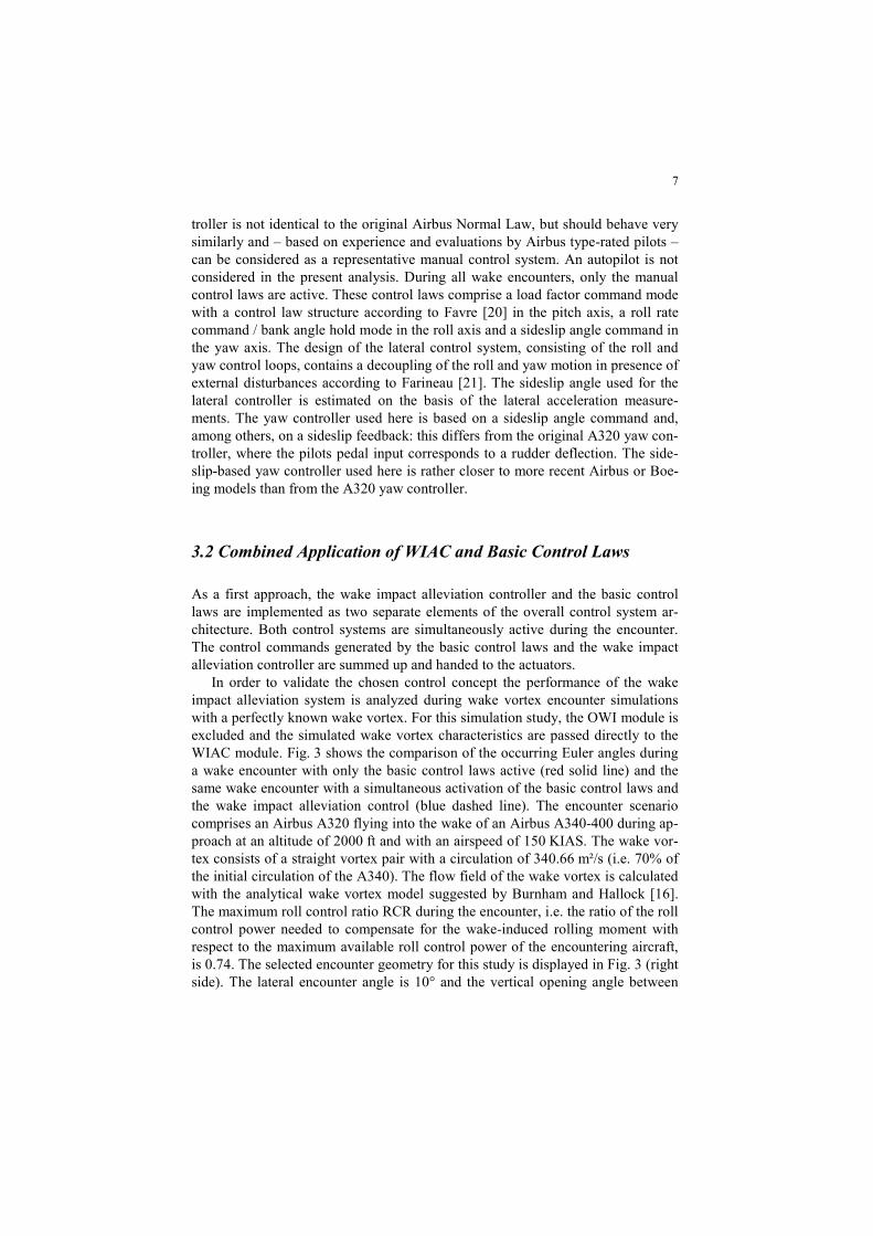
In order to validate the chosen control concept the performance of the wake impact alleviation system is analyzed during wake vortex encounter simulations with a perfectly known wake vortex. For this simulation study, the OWI module is excluded and the simulated wake vortex characteristics are passed directly to the WIAC module. Fig. 3 shows the comparison of the occurring Euler angles during a wake encounter with only the basic control laws active (red solid line) and the same wake encounter with a simultaneous activation of the basic control laws and the wake impact alleviation control (blue dashed line). The encounter scenario comprises an Airbus A320 flying into the wake of an Airbus A340-400 during ap-proach at an altitude of 2000 ft and with an airspeed of 150 KIAS. The wake vor-tex consists of a straight vortex pair with a circulation of 340.66 m²/s (i.e. 70% of the initial circulation of the A340). The flow field of the wake vortex is calculated with the analytical wake vortex model suggested by Burnham and Hallock [16]. The maximum roll control ratio RCR during the encounter, i.e. the ratio of the roll control power needed to compensate for the wake-induced rolling moment with respect to the maximum available roll control power of the encountering aircraft, is 0.74. The selected encounter geometry for this study is displayed in Fig. 3 (right side). The lateral encounter angle is 10° and the vertical opening angle between
8
the flight path of the generator aircraft and the encountering aircraft is 0° where-upon the vortex core is located 2 m above the center of gravity of the encountering aircraft. This corresponds to the reference encounter scenario of [10], whereupon the terms and definitions of the encounter geometry defined in [10] are adopted here. The pilot does not apply any control inputs during the encounter. Conse-quently any control actions result from the basic control feedback loops and/or the wake impact alleviation control system. All encounter simulations are space-fixed. That means that the wake vortex has a fixed location and the disturbance affecting the aircraft depends on the aircraft trajectory through the vortex, which corre-sponds to a realistic wake vortex encounter. In contrast to time-fixed encounter simulations, which induce the same time-dependent wake disturbance on the air-craft (which are also often used for wake vortex comparison studies), the disturb-ance acting on the aircraft with and without active WIAC is different because the control actions coming from WIAC influence the flight path. This approach is se-lected deliberately in order to include all physical effects in the analysis and to be able to allow a final evaluation which control law leads to the lowest wake impact during the encounter. Note that a complete evaluation of WIAC requires a high number of encounters with different encounter geometries, wake vortices, etc. as shown in [6][8][9][10]. However, in order to illustrate and discuss the effects shown hereafter in the present paper the encounter scenario considered here is suf-ficient.
Fig. 3 shows that the additional activation of the WIAC strongly reduces the wake-induced aircraft response compared to the same encounter when only the basic control laws are active. It can be noticed as well that even with active wake impact alleviation control there are still significant Euler angle deviations present, which was not expected for a case in which the wake vortex is perfectly known (same vortex in the simulation as used as input of the WIAC).
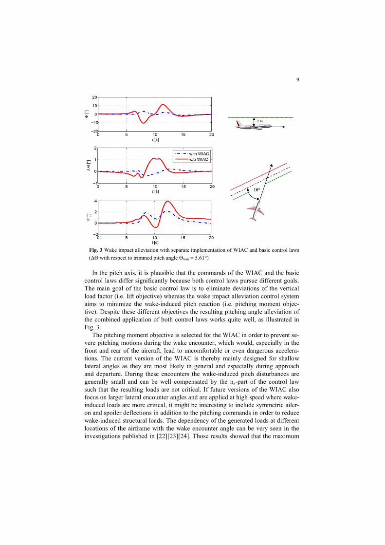
The unsatisfying performance of the WIAC system for this idealized case can-not be caused by a lack of control authority, since no actuator limit was reached. The actuator dynamics are not directly taken into account in the WIAC but the bandwidth of the actuators is significantly above the frequencies excited in the scenario shown: the poor performance observed also cannot be explained by the actuator dynamics. The fact that the WIAC system can only (directly) act upon three of the six degrees of freedom of the airplane is not the cause of the observed poor performance either since the main deviations are observed on the degrees of freedom which can be controlled. The reason for the suboptimal performance of the wake impact alleviation control was found to originate from the suboptimal combination of WIAC and the basic control laws. In order to compensate for the wake-induced rolling moments, it is necessary that the control surface commands commanded by WIAC correspond to the control surface deflections that the actua-tors finally realize. The time histories of the actuator deflections in Fig. 4 demon-strate that the actual control surface deflections differ from the WIAC commands because the latter are summed up with the commands of the basic control laws which sometimes conflict the WIAC commands.
9
Fig. 3 Wake impact alleviation with separate implementation of WIAC and basic control laws
(ΔΘ with respect to trimmed pitch angle Θtrim = 5.61°)
In the pitch axis, it is plausible that the commands of the WIAC and the basic control laws differ significantly because both control laws pursue different goals. The main goal of the basic control law is to eliminate deviations of the vertical load factor (i.e. lift objective) whereas the wake impact alleviation control system aims to minimize the wake-induced pitch reaction (i.e. pitching moment objec-tive). Despite these different objectives the resulting pitching angle alleviation of the combined application of both control laws works quite well, as illustrated in Fig. 3.
The pitching moment objective is selected for the WIAC in order to prevent se-vere pitching motions during the wake encounter, which would, especially in the front and rear of the aircraft, lead to uncomfortable or even dangerous accelera-tions. The current version of the WIAC is thereby mainly designed for shallow lateral angles as they are most likely in general and especially during approach and departure. During these encounters the wake-induced pitch disturbances are generally small and can be well compensated by the nz-part of the control law such that the resulting loads are not critical. If future versions of the WIAC also focus on larger lateral encounter angles and are applied at high speed where wake-induced loads are more critical, it might be interesting to include symmetric ailer-on and spoiler deflections in addition to the pitching commands in order to reduce wake-induced structural loads. The dependency of the generated loads at different locations of the airframe with the wake encounter angle can be very seen in the investigations published in [22][23][24]. Those results showed that the maximum
10
loads for the wing and the horizontal tailplane occurred at an encounter angle of 90° whereas the maximum loads on the vertical tailplane results from a combina-tion of perturbation frequency and disturbance amplitude. The shallower the en-counter angle is, the lower is the frequency of the perturbation. With very shallow angles the aircraft directional stability continuously turn the aircraft “into the wind” which reduces the loads at the vertical tailplane. The steeper the encounter angle is, the lower is the wake-induced sideslip angle and therefore the disturb-ance amplitude. The encounter angle value at which the critical vertical tail loads are obtained depends on various factors of the aircraft, of the current flight point, etc. For instance, on the A400M configuration investigated in [23] the critical en-counter angles were between 32° (at 180 kt IAS) and 19° (at 300 kt IAS).
Fig. 4 Control commands of WIAC and the basic control laws as well as actual control surface
deflections for separate implementation of WIAC and basic control laws [10] In the roll axis, both control systems principally pursue the same goal of mini-
mizing deviations of the rolling motion. The basic roll control law follows the roll command of the pilot. In the present case with no pilot input this means that it aims to keep the roll rate to zero. The WIAC likewise tries to prevent a rolling motion by countervailing the wake-induced rolling moment. The effect that the two controllers nevertheless mutually impair their performance results from the fact that the sideslip-angle-induced rolling moment of the wake vortex is compen-sated by both control laws, which leads to a slight oversteering in the roll axis. Due to the specific design of the basic lateral control law with the decoupling of the roll and yaw axis response to external disturbances, a sideslip angle feedback signal is included in the roll controller of the basic control laws. This corresponds to an artificial modification of the aerodynamic dihedral effect derivative Clβ (i.e.

11
the derivative of the rolling moment coefficient Cl with respect to the sideslip an-gle β) and allows the elimination of the natural coupling of the roll axis due to sideslip. The problem of the combination of the WIAC and the basic control laws is that the WIAC does not account for this decoupling of the yaw and roll axis in the basic control laws. Instead, the aileron command of the WIAC contains a component to compensate for the roll response induced by the sideslip disturbance of the wake vortex as if the natural yaw-roll coupling of the aircraft would still ex-ist. As a consequence the WIAC (in that version) implicitly commands a decou-pling of the yaw and roll axis again. This leads to the observed oversteering in the roll axis.
As this oversteering occurs as a result of the artificial decoupling of roll and yaw axis, it is dependent on the design of the basic control laws. For different roll control laws without this decoupling the observed conflict in the roll axis with the WIAC system does not occur.
In the yaw axis, a conflict of the goals of the two control systems is more obvi-ous again than in the roll axis. The purpose of the basic control laws is to follow the reference sideslip angle commanded by pedal inputs of the pilot. As the pilot rarely commands sideslip angles (only in special maneuvers such as a decrab ma-neuver during a crosswind landing for instance), this corresponds to the minimiza-tion of sideslip angle excursions during the majority of the flight. The wake im-pact alleviation control, in contrast, tries to minimize the yaw rate. This provokes that the two controllers in the yaw axis work against each other because the basic control laws support the aircraft’s tendency to turn its nose into the wind whereas the WIAC tries to keep the aircraft nose straight. In order to prevent this behavior, a smarter combination of both control commands than a simple summation is re-quired. In fact, the conflict in the yaw axis is equivalent to the conflict observed in the pitch axis. In that case the nz control law (load factor) of the basic controller also tries to turn the aircraft into the wind by minimizing nz deviations, which are by a constant factor correlated to the angle of attack α, and the WIAC aims to prevent any pitch rotations. The difference just seems to be that the bandwidth of the dis-turbance in the yaw axis is larger than in the pitch axis. In the pitch axis, the per-formance of the WIAC is not significantly impaired by the control commands of the nz control loop. In the case of the present control system, the nz control loop of the basic control laws is far less aggressive than the sideslip control loop. This ef-fect is strongly dependent on the specific tuning of control gains and might be dif-ferent for a different control design.
4 Improved Integration of WIAC and Basic Control Laws
After the simple summation of the control commands of the WIAC and basic control system has shown potential for improvement, an improved integration of

12
the two control systems is proposed. As already mentioned in the previous section, the interaction of the basic control system and WIAC is strongly dependent on the specific design of the basic control laws. The presented approach suggests a modi-fication of the control architecture and possibly of the tuning of the basic control law used in this work.
The focus is thereby on the improved combination of the lateral directional control because the disturbance and hence the resulting aircraft reaction during the wake vortex encounter is much stronger in the lateral directional than in the longi-tudinal axis. In the longitudinal axis, even without the WIAC system the pitch an-gle deviation during the wake vortex encounter stays in the order of 1°, which can be considered as uncritical. Furthermore, the current implementation of the com-bined application of the WIAC and the basic control law in the longitudinal axis already works acceptably well. Despite the different control objective of the basic control law, which interacts with the WIAC command (cf. Fig. 4), the resulting control surface deflection leads to a significant additional reduction of the occur-ring pitch angle (cf. Fig. 3) and the remaining pitch angle deviation is negligibly small. Further adaptations of the longitudinal control are thus not stringently need-ed.
The approach taken for the improved integration of the WIAC in the lateral di-rectional control architecture corresponds to the concept presented in the patent [25]. The main performance improvement of a combined application of the WIAC and the basic control laws can be achieved by the avoidance of the overcompensa-tion in the roll axis due to the double consideration of the wake-induced rolling moment component resulting from the wake-induced sideslip angle in both control laws. In order to prevent this, the consideration of this rolling moment component needs to be excluded from one of the two control laws. In the basic control law, it can be excluded by removing the artificial decoupling of the roll and yaw motion in terms of the feedback of the sideslip angle to the roll controller. The disad-vantage of this approach is that disabling the (estimated) sideslip angle feedback in the basic control law would lead to a different overall behavior of the basic con-trol law and would thus also influence the dynamic behavior of the aircraft throughout the flight. This is the reason why the second alternative of excluding the wake-induced rolling moment component resulting from the wake-induced sideslip angle from the WIAC module is preferred here. For this purpose, the side-slip-angle-induced component of the wake-induced rolling moment is retrospec-tively subtracted from the entire wake-induced rolling moment ���� determined by means of the AIM:
Δ�����,��� = Δ���� − �� ∙ � ∙ � ∙ ��� ∙ ���,
whereupon �����,��� is the resulting rolling moment used for the command generation within WIAC, ��� the rolling moment coefficient derivative with re-
spect to the sideslip angle, ��� the equivalent wake-induced sideslip angle,� is wing area,� the half span of the wing and �� the dynamic pressure. The fictitious

13
parameter ��� describes an equivalent sideslip angle at the center of gravity, which would cause the same resulting forces and moments as the inhomogeneous wind field of the wake vortex. Ignoring the negligible interaction with the longitu-dinal axis and the influence of the sideslip angle on the roll and yaw moment, ��� can easily be derived from the wake-induced side force ���� provided by the AIM by inverting the aerodynamic model of the aircraft:
��� = ����
�� ∙ � ∙ ��� ∙ ���
,
whereupon ��� represents the aerodynamic side force coefficient derivative
with respect to the sideslip angle. The effect of this adaptation of the WIAC implementation on the wake impact
alleviation performance is demonstrated in Fig. 5.
Fig. 5 Impact of wake encounter on Euler angles for different variants of the WIAC integration
with basic control laws (ΔΘ with respect to trimmed pitch angle Θtrim = 5.61°)
The red solid line and the blue dash-dot line are identical to Fig. 3 and illustrate
the aircraft response when only the basic control laws are active (red solid line) and when the original WIAC is applied in combination with the basic control laws (blue dash-dot line). The green dotted line shows the aircraft response for the air-craft with the basic control laws and the modified WIAC system without the side-slip-angle-induced component of the wake-induced rolling moment considered in the command generation for the rolling moment. It can be noticed that this modifi-cation leads to a significant reduction of the bank angle (Φ) excursion and also to a slight improvement of the heading deviation (Ψ) compared to the application of the original the WIAC in combination with the basic control laws.

14
A further improvement of the heading excursion can be achieved by additional-ly avoiding the described conflict of WIAC and the basic control laws with respect to the pursued goals in the yaw axis. This can be achieved by a modification of the command value of the yaw control loop of the basic control law. Instead of using the pure pedal input commanded by the pilot as a reference value for the yaw con-trol, the wake-induced sideslip angle is added to the commanded pedal input to form the new reference value as shown in Fig. 6. When the commanded sideslip angle from the pilot is zero, as it is assumed for the present study and usually the case during flight, the basic yaw control law receives the wake-induced sideslip angle ��� as a reference value.
The way the control commands of WIAC δrudder,WIAC (which corresponds to the blue solid line in Fig. 4) and the command of the basic control law δrudder,basic ctrl (which corresponds to the green dashed line in Fig. 4) are summed up to form the resulting control surface command δrudder,cmd remains unchanged.
Fig. 6 Modification of yaw controller command value
The control structure shown in Fig. 6 thereby assumes that the basic yaw con-
trol law does not possess an individual gain in the feedforward branch of the commanded sideslip angle. If such a gain exists and different gains are applied for the feedforward and the feedback branches, it has to be ensured that the wake-induced sideslip angle command is assigned to the feedback gains as shown in Fig. 7. The feedforward gain KFFβ is, in this case, tuned to achieve the desired air-craft response to pedal inputs. The purpose of adding ��� to the commanded val-ue ������ is to exclude this component from the control error that is compensated
by the feedback. It thus needs to be applied with the corresponding feedback gains KPβ and KIβ for the feedback signal of the sideslip angle (in this case the feedback signal of the estimated sideslip angle ����).
15
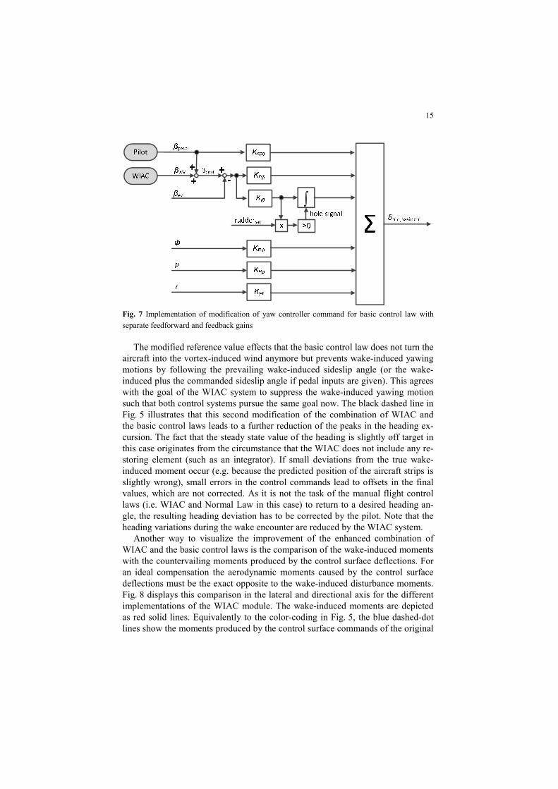
Fig. 7 Implementation of modification of yaw controller command for basic control law with
separate feedforward and feedback gains
The modified reference value effects that the basic control law does not turn the
aircraft into the vortex-induced wind anymore but prevents wake-induced yawing motions by following the prevailing wake-induced sideslip angle (or the wake-induced plus the commanded sideslip angle if pedal inputs are given). This agrees with the goal of the WIAC system to suppress the wake-induced yawing motion such that both control systems pursue the same goal now. The black dashed line in Fig. 5 illustrates that this second modification of the combination of WIAC and the basic control laws leads to a further reduction of the peaks in the heading ex-cursion. The fact that the steady state value of the heading is slightly off target in this case originates from the circumstance that the WIAC does not include any re-storing element (such as an integrator). If small deviations from the true wake-induced moment occur (e.g. because the predicted position of the aircraft strips is slightly wrong), small errors in the control commands lead to offsets in the final values, which are not corrected. As it is not the task of the manual flight control laws (i.e. WIAC and Normal Law in this case) to return to a desired heading an-gle, the resulting heading deviation has to be corrected by the pilot. Note that the heading variations during the wake encounter are reduced by the WIAC system.
Another way to visualize the improvement of the enhanced combination of WIAC and the basic control laws is the comparison of the wake-induced moments with the countervailing moments produced by the control surface deflections. For an ideal compensation the aerodynamic moments caused by the control surface deflections must be the exact opposite to the wake-induced disturbance moments. Fig. 8 displays this comparison in the lateral and directional axis for the different implementations of the WIAC module. The wake-induced moments are depicted as red solid lines. Equivalently to the color-coding in Fig. 5, the blue dashed-dot lines show the moments produced by the control surface commands of the original

16
WIAC and basic control laws, the green dotted lines refer to these moments for the WIAC implementation without the consideration of the sideslip-angle-induced rolling moment component in the command generation (and the original basic control laws) and the black dashed lines illustrate these moments for the WIAC implementation without the consideration of the sideslip-angle-induced rolling moment component in the command generation in combination with the modified yaw command value in the basic control law.
Fig. 8 Comparison of moments (L: rolling moment, N: yawing moment) resulting from the wake
vortex and the control surface deflections for different variations of WIAC / control law integration
It can be noticed in Fig. 8 that the removal of the sideslip-angle-induced rolling
moment component from the command generation of the WIAC leads to an im-proved match of the rolling moment of the wake vortex (red solid line) and of the control surface deflections (green dotted line). This match can be further improved if the wake-induced sideslip angle is added to the command value of the yaw loop of the basic control laws (black dashed line). In the yaw axis, only little benefit can be noticed due to the first modification of the WIAC (green dotted line), but the addition of the wake-induced sideslip angle to the command value of the yaw controller (black dashed line) provokes a noticeable improvement of the match of the yawing moments. Nevertheless, the first peak of the wake-induced yawing moments is not well matched by the moments generated by the control surfaces. This explains the slight offset in the steady state heading angle in Fig. 5. The rea-son for this imperfect match is expected to result from the imprecisions in the pre-

17
dicted positions of the aircraft strips, which in turn impact the wake-induced dis-turbance velocities based on which the AIM determines the wake-induced forces and moments. Such small deviations can occur because the predicted strip position is determined by a simple propagation of the current steady aircraft motion (ne-glecting aircraft accelerations) for a fixed timespan of 0.1 s. The 0.1 s approxi-mately correspond to the actuator delays whereupon the actual actuator delay can slightly differ from this value depending on the particular actuator dynamics. Er-rors resulting from these simplifications do, however, not have a significant influ-ence and therefore do not justify a more complex modelling. The underlying idea of the 0.1 s propagation is to anticipate the moments that need to be compensated in 0.1 s from now and to already command the required control surface deflections for compensating those moments, because these commands will only be effective in 0.1 s from now. As the magnitude of the wake-induced yawing moment is much smaller than the disturbance in the rolling axis, the absolute deviations of the yaw-ing moments are still comparably small though and still allow a good wake impact alleviation performance.
4 Conclusions and Outlook
The present paper demonstrates a successful approach to mitigate the aircraft reaction during wake vortex encounters. It presents a specific control system, called OWIDIA (Online Wake IDentification and Impact Alleviation), that com-bines the onboard wake identification on basis of remote lidar measurements in a short distance in front of the aircraft with a control module which determines and compensates the corresponding wake-induced aircraft reaction. The paper de-scribes the different components of the OWIDIA system and focuses on the inte-gration of this system into the overall flight control system architecture of the air-craft. A simple summation of the control commands of the wake impact alleviation control system and the aircraft’s basic control laws is found to impair the wake impact alleviation performance. Due to conflicting goals of the two con-trol systems and a double consideration of specific components, the commands of the basic control laws unfavorably interfere with the required control surface de-flections of the OWIDIA system that would lead to the compensation of the wake-induced disturbance moments. This problem is successfully addressed by the pre-sented improved integration concept, which prevents these undesired interactions and thereby allows achieving a significantly better wake impact alleviation per-formance.
Concerning the wake impact alleviation performance of the basic control laws it needs to be considered that the wake vortex disturbance does not represent a particular design requirement for this control system. Here the idea would be to steer the scheduling of the feedback controller that determines handling qualities

18
and load alleviation function towards higher rejection of the disturbances affecting the rigid body motion when a wake vortex has been detected.
Thanks to the OWIDIA system the information of an upcoming wake vortex encounter is available and could be used for a gain adaptation of the basic control laws. This combined application of the current feedforward disturbance rejection of the OWIDIA system and an additional specific feedback control is expected to further improve the wake impact alleviation and should therefore by analyzed in future studies. In cases of an imperfect wake characterization this extension would additionally increase the robustness of the wake impact alleviation performance because the feedback control could still successfully alleviate the wake-vortex-induced aircraft response even for imperfect feedforward disturbance cancellation by the OWIDIA system.
Another potential issue for future studies is the analysis of the exact objective of the wake impact alleviation system. The current control approach of the OWIDIA system assumes that wake-induced rotational accelerations should be compensated. To what extend other impacts of the wake vortex such as vertical accelerations or flight path deviations should also be considered by the control laws would be worth investigating in a future study. Concerning the prevention of the wake-induced yawing motion, as it is currently the goal of the WIAC, it should be ensured that the total loads on the vertical stabilizer remain within the design load envelope. In addition to the loads induced by the wake vortex and due to the inertial accelerations, aggressive pilot inputs can be triggered by the wake vortex encounter and eventually could lead to a vertical separation as in the accident of American Airlines flight 587 in 2001 [27]. A rulemaking task has been started by the EASA [28] following the observation that potentially dangerous rudder pilot inputs do occur during upset conditions and it appears likely that the certification requirements for the vertical tailplane structure are likely to become more strin-gent in the near future.
Acknowledgements
The presented work was generated within the DLR-internal projects “Wetter & Fliegen” (English translation: Weather & Flying) and WOLV (Wetteroptimierter Luftverkehr, English translation: weather-optimized air traffic). Parts of the source code were developed for gust load alleviation purposes within CleanSky Smart Fixed Wing Aircraft under the Grant Agreement Number CS2JU-AIR-GAM-2014-2015-01 and adapted for the application with wake vortices.
19
References
[1] ICAO, “Procedures for Air Navigation Services - Air Traffic Management”, Technical re-port, Doc 4444 ATM/501, ICAO, 2007.
[2] Flight Safety Digest, Vol. 21 No. 3-4, “Data Show That U.S. Wake-turbulence Accidents Are Most Frequent at Low Altitude and During Approach and Landing”, Flight Safety Foundation, March-April 2002.
[3] Hahn, K.-U., “Coping with Wake Vortex”, International Congress of Aeronautical Scienc-es, Toronto, Canada, 2002, pp. 732.1–732.14.
[4] Schwarz, C. W., Hahn, K.-U., “Automated Pilot Assistance for Wake Vortex Encounters”. Aerospace Science and Technology 15 (5 2011), pp. 416–421, DOI: 10.1016/j.ast. 2010.09.008.
[5] Fischenberg, D., “Strömungsermittlungsverfahren/Flow Determination Method/Procédé de détermination d’écoulement”, Patent No. EP 2 340 438 B1, European Patent Office 2013.
[6] Ehlers, J., Niedermeier, D., Fischenberg, “Wake Impact Alleviation Control Based on Wake Identification”, Journal of Aircraft 52.6 (2015), pp. 2077–2089, DOI: 10.2514/1.C033157.
[7] Luckner, R.: “Modeling and Simulation of Wake Vortex Encounters: State-of-the-Art and Challenges”, AIAA-2012-4633, AIAA Modeling and Simulation Technologies Conference, Minneapolis, MN, USA, August 2012, DOI: 10.2514/6.2012-4633.
[8] Fezans, N., Schwithal, J., Fischenberg, D., “In-flight remote sensing and identification of gusts, turbulence, and wake vortices using a Doppler LIDAR”, CEAS Aeronautical Journal 8 (2017), pp. 313-333, DOI: 10.1007/s13272-017-0240-9.
[9] Ehlers, J., Fezans, N., “Airborne Doppler LiDAR Sensor Parameter Analysis for Wake Vortex Impact Alleviation Purposes”, EuroGNC 2015, 13-15 April 2015, Toulouse, France, in “Advances in Aerospace Guidance, Navigation and Control”, Springer, pp. 433-453, Toulouse, April 2015, ISBN 978-3-319-17517-1.
[10] Schwithal , J., “Lidar-based Wake Identification and Impact Alleviation”, DLR research re-port ISSN: 1434-8454 / ISRN: DLR-FB--2017-59, PhD thesis, Technische Universität Braunschweig, 2017.
[11] Bauer, T., Vechtel, D., Abdelmoula, F., Immisch, T.: “In-Flight Wake Encounter Prediction with the Wake Encounter Avoidance and Advisory System”, AIAA Atmospheric and Space Environments Conference, Atlanta, GA, USA, 2014, DOI: 10.2514/6.2014-2333.
[12] Estes, S. L., Koch, M. E., Lunsford, C. R., Mendolia, A. S., “Wake Turbulence Avoidance Automation: Evaluation of Feasibility and Impact”, Digital Avionics Systems Conference, Seattle, Washington, USA, 2011, DOI: 10.1109/DASC.2011.6096094.
[13] Kloidt, S., “Beiträge zum Entwurf eines Flugregelungssystems zur Reduktion des Wir-belschleppeneinflusses” (English: Contributions to the Design of a Flight Control System for the Reduction of the Wake Vortex Impact), PhD Thesis, TU Berlin, Germany, 2007.
[14] Looye, G., Lombaerts, T., Kier, T., “Design and Flight Testing of Feedback Control Laws”, In: DLR research report ISSN: 1434-8454 / ISRN: DLR-FB--2012-02, The DLR Project Wetter & Fliegen, ed. Gerz. T., Schwarz, C., pp. 162-170, 2012.
[15] Rafi, M., Steck, J., “Reponse and Recovery of an MRAC Advanced Flight Control System to Wake Vortex Encounters”, AIAA Infotech@Aerospace, Boston, MA, USA, 2013.
[16] Burnham, D.C., Hallock, J. N., “Chicago Monoacoustic Vortex Sensing System, Vol. IV: Wake Vortex Decay”, Tech. rep. DOT-TSC-FAA-79-18, IV, NIS, 1982.
[17] Fischenberg, D., “Bestimmung der Wirbelschleppencharakteristik aus Flugmessdaten (Eng-lish: Determination of Wake Vortex Characteristics from Flight Test Data)”, Deutscher Luft- und Raumfahrtkongress, Stuttgart, Germany, 2002.
[18] Fischenberg, D., “A method to validate wake vortex encounter models from flight test da-ta”, International Congress of the Aeronautical Sciences, Nice, France, 2010.
20
[19] Niedermeier, D. and Lambregts, A. A., “Fly-by-wire augmented manual control – basic de-sign and considerations“, International Congress of the Aeronautical Sciences, Brisbane, Australia, 2012.
[20] Favre, C., “Fly-by-Wire for Commercial Aircraft: The Airbus Experience”, International Journal of Control 59.1 (1994), pp. 139–157, DOI: 10.1080/00207179408923072.
[21] Farineau, J., “Lateral Electric Flight Control Laws of A Civil Aircraft Based Upon Eigen Structure Assignment Technique”, Guidance, Navigation and Control Conference, Boston, MA, USA, 1989, DOI: 10.2514/6.1989-3594.
[22] Hesse, H. and Palacios, R., “Dynamic Load Alleviation in Wake Vortex Encounters”, Jour-nal of Guidance, Control, and Dynamics, Vol. 39, No. 4, pp. 801-813, January 2016. DOI: 10.2514/1.G000715.
[23] Torralba, M.A., et al. “Wake Vortex Encounter Loads. Flight Tests and Numerical Simula-tions”, International Congress of the Aeronautical Science, St. Petersburg, Russia, 2014.
[24] Kier, T. M., “An Integrated Loads Analysis Model for Wake Vortex Encounters”, In Pro-ceedings of the IFASD 2013, Bristol, UK, June 2013. ISBN: 978-1634391023.
[25] Schwithal, J. and Niedermeier, D., “Verfahren zur Reduzierung des Einflusses von Luft-strömungsverwirbelungen auf Luftfahrzeuge und Luftfahrzeugregelungseinheit (English: procedure for the reduction of the influence of airstream turbulence on aircraft and aircraft control unit)”, Patent DE 10 2013 112 059. 2017.
[26] Ossmann, D. and Poussot-Vassal, C., “Minimal Order Disturbance Estimator Design for Aircraft Load Alleviation Control”, IEEE CCTA 2018, Copenhagen, Denmark, 2018.
[27] NTSB, “In-Flight Separation of Vertical Stabilizer; American Airlines Flight 587 Airbus Industrie A300-605R, N14053, Belle Harbor, New York, November 12, 2001”, Aircraft Accident Report NTSB/AAR-04/04. Washington, DC, USA, 2004.
[28] EASA, “Notice of Proposed Amendment 2017-18: Unintended or inappropriate rudder us-age – rudder reversals”, EASA-RMT.0397, Nov. 2017.