intel® rapid boot toolkit · intel® rapid boot toolkit . user guide . for intel ® server boards...
TRANSCRIPT
Intel® Rapid Boot Toolkit User Guide
For Intel® Server Boards S3000AH, S3000PT, S5000AL and S5000SL
April 11, 2007
Reference Number: D96629-001

Legal Statements INFORMATION IN THIS DOCUMENT IS PROVIDED IN CONNECTION WITH INTEL PRODUCTS FOR THE PURPOSE OF SUPPORTING INTEL DEVELOPED SERVER BOARDS AND SYSTEMS. NO LICENSE, EXPRESS OR IMPLIED, BY ESTOPPEL OR OTHERWISE, TO ANY INTELLECTUAL PROPERTY RIGHTS IS GRANTED BY THIS DOCUMENT. EXCEPT AS PROVIDED IN INTEL'S TERMS AND CONDITIONS OF SALE FOR SUCH PRODUCTS, INTEL ASSUMES NO LIABILITY WHATSOEVER, AND INTEL DISCLAIMS ANY EXPRESS OR IMPLIED WARRANTY, RELATING TO SALE AND/OR USE OF INTEL PRODUCTS INCLUDING LIABILITY OR WARRANTIES RELATING TO FITNESS FOR A PARTICULAR PURPOSE, MERCHANTABILITY, OR INFRINGEMENT OF ANY PATENT, COPYRIGHT OR OTHER INTELLECTUAL PROPERTY RIGHT. Intel products are not intended for use in medical, life saving, life sustaining, critical control or safety systems, or in nuclear facility applications.
Intel may make changes to specifications and product descriptions at any time, without notice. Designers must not rely on the absence or characteristics of any features or instructions marked "reserved" or "undefined." Intel reserves these for future definition and shall have no responsibility whatsoever for conflicts or incompatibilities arising from future changes to them. The information here is subject to change without notice. Do not finalize a design with this information.
Intel® Active Management Technology requires the platform to have an Intel® AMT-enabled chipset, network hardware and software, as well as connection with a power source and a corporate network connection. With regard to notebooks, Intel AMT may not be available or certain capabilities may be limited over a host OS-based VPN or when connecting wirelessly, on battery power, sleeping, hibernating or powered off. For more information, see http://www.intel.com/technology/iamt.
The products described in this document may contain design defects or errors known as errata which may cause the product to deviate from published specifications. Current characterized errata are available on request.
Contact your local Intel sales office or your distributor to obtain the latest specifications and before placing your product order.
Copies of documents which have an order number and are referenced in this document, or other Intel literature, may be obtained by calling 1-800-548-4725, or by visiting Intel's Web Site.
Intel, the Intel logo, and Xeon are trademarks of Intel Corporation in the U.S. and other countries.
*Other names and brands may be claimed as the property of others.
Copyright © 2007, Intel Corporation. All rights reserved.
Revision History Date Revision Reference # Description
April 11, 2007 1.0 D96629-001 Initial release.
ii Intel® Rapid Boot Toolkit User Guide Ref# D96629-001

Contents Legal Statements...............................................................................ii
Revision History ................................................................................ii
Contents ...........................................................................................iii
1 Introduction................................................................................1 Overview......................................................................................................... 1 What’s in the Toolkit?........................................................................................ 1 What is the Payload Size in Flash?....................................................................... 1 About the Tools ................................................................................................ 2
2 Toolkit Installation......................................................................3
3 Using the Toolkit .........................................................................7 Creating a BIOS Flash Payload............................................................................ 7 Creating a USB Flash Payload............................................................................. 7 BIOS System Recovery...................................................................................... 7
BIOS system recovery for DP systems......................................................... 8 BIOS system recovery for UP systems......................................................... 8
4 Intel® Rapid Boot BIOS ...............................................................9 System BIOS Versions....................................................................................... 9 What’s in the BIOS?.......................................................................................... 9 What’s not in the BIOS? ...................................................................................12
5 Payload Creation .......................................................................15
6 Sample Payloads .......................................................................17 Generic Payload ..............................................................................................17
Commands supported by Generic Payload ..................................................17 How To Build the Generic Payload .............................................................18
Launcher Payload ............................................................................................20 Modes of Operation .................................................................................20
Direct mode...............................................................................20 Scan mode ................................................................................20
How To Build the Launcher Payload ...........................................................20
7 The Tools...................................................................................23 Intel® One Boot Flash Update............................................................................23
Sample Intel® OFU Configuration File.........................................................23 Configuration File Automation ...................................................................24
Menu Command .........................................................................24 Prompt Command.......................................................................24 Frufield Command ......................................................................25
Ref# D96629-001 Intel® Rapid Boot Toolkit User Guide iii
RMM Update Automation..........................................................................25 Intel® System Configuration Utility (SysCfg)........................................................25
SMI Driver .............................................................................................26 pyFlash ..........................................................................................................26 Power Console ................................................................................................26
jQ (Simple Job Queuing) ..........................................................................27 Qadmin Usage........................................................................................28 Qfeed Usage ..........................................................................................28
8 Glossary ....................................................................................29
9 Tips and Tricks ..........................................................................31 Quick Start Guide ............................................................................................31 Payload Development.......................................................................................31
A. Appendix ..................................................................................33 Linux* Compilation ..........................................................................................33 Kboot 34 NFS Server Setup ............................................................................................34 DHCP Server Configuration for Generic Example Payload.......................................35 POST Codes....................................................................................................35 SOAP Error Codes............................................................................................37
iv Intel® Rapid Boot Toolkit User Guide Ref# D96629-001
11 Introduction Introduction
Overview The Intel® Rapid Boot Toolkit (Release 1) is a collection of tools for the administrators and programmers supporting High Performance Computing (HPC) clusters of Intel® server boards. With this toolkit, you can boot the HPC nodes using the Intel® Rapid Boot BIOS, and then launch a flash-based payload that supports your HPC provisioning needs. By using the Intel Rapid Boot Toolkit, you can boot your entire HPC cluster faster and then provision it in a fraction of the time required by the conventional BIOS and PXE provisioning method.
What’s in the Toolkit? Intel Rapid Boot Toolkit includes the following components:
• Intel® Rapid Boot BIOS • Sample Payloads • Tools
o To create payloads (Payload Tool Chain) o BIOS, BMC Update (Intel® One Boot Flash Update) o BIOS, BMC Configuration (Intel® System Configuration Utility–SysCfg) o Payload Update (pyFlash) o Remote Power Management (Power Console) o Job Distribution Mechanism (jQ)
What is the Payload Size in Flash? The payload area in the BIOS flash area is 1.28 MB.
Intel® Server Boards S5000AL and S5000SL have a 4 MB BIOS flash chip, while Intel® Server Boards S3000AH and S3000PT have a 2 MB BIOS flash chip. In systems with the 4 MB BIOS flash area, the flash area is divided into two banks – Primary and Secondary. This is to provide failover support if one bank becomes corrupted.
Out of the 2 MB BIOS flash area, 12 blocks (64K each) are used by the Intel Rapid Boot BIOS while the remaining 20 blocks (totaling 1.28 MB) are available for a payload (a user customizable embedded kernel). The Rapid Boot payload can support any Operating System that is EFI aware and fits into the allotted space. It does not support legacy Operating Systems.
Ref# D96629-001 Intel® Rapid Boot Toolkit User Guide 1

About the Tools Intel Rapid Boot Toolkit uses open source tools like kboot, eLilo and GNU EFI tool chain. Original sources and the required patches are provided. The patches are provided under the GPL License.
Intel Rapid Boot Toolkit provides capabilities for creating payloads, adding the payload to the BIOS flash area, and passing control of the system to the payload early in the system boot process.
2 Intel® Rapid Boot Toolkit User Guide Ref# D96629-001
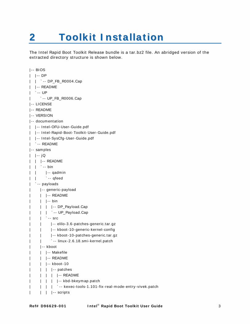
22 Toolkit Installation Toolkit InstallationThe Intel Rapid Boot Toolkit Release bundle is a tar.bz2 file. An abridged version of the extracted directory structure is shown below.
|-- BIOS
| |-- DP
| | `-- DP_FB_R0004.Cap
| |-- README
| `-- UP
| `-- UP_FB_R0006.Cap
|-- LICENSE
|-- README
|-- VERSION
|-- documentation
| |-- Intel-OFU-User-Guide.pdf
| |-- Intel-Rapid-Boot-Toolkit-User-Guide.pdf
| |-- Intel-SysCfg-User-Guide.pdf
| `-- README
|-- samples
| |-- jQ
| | |-- README
| | `-- bin
| | |-- qadmin
| | `-- qfeed
| `-- payloads
| |-- generic-payload
| | |-- README
| | |-- bin
| | | |-- DP_Payload.Cap
| | | `-- UP_Payload.Cap
| | `-- src
| | |-- elilo-3.6-patches-generic.tar.gz
| | |-- kboot-10-generic-kernel-config
| | |-- kboot-10-patches-generic.tar.gz
| | `-- linux-2.6.18.smi-kernel.patch
| |-- kboot
| | |-- Makefile
| | |-- README
| | |-- kboot-10
| | | |-- patches
| | | | |-- README
| | | | |-- kbd-bkeymap.patch
| | | | `-- kexec-tools-1.101-fix-real-mode-entry-vivek.patch
| | | |-- scripts
Ref# D96629-001 Intel® Rapid Boot Toolkit User Guide 3

| | | `-- utils
| | |-- patches
| | | |-- kboot-10
| | | `-- linux-2.6.18
| | | `-- linux-2.6.18.smi-kernel.patch
| | `-- src
| | `-- kboot-10-orig.tar.gz
| |-- launcher-payload
| | |-- README
| | |-- bin
| | | |-- DP_Payload.Cap
| | | `-- UP_Payload.Cap
| | `-- src
| | |-- elilo-3.6-patches-launcher.tar.gz
| | |-- kboot-10-launcher-kernel-config
| | `-- kboot-10-patches-launcher.tar.gz
| `-- patches
| `-- linux-2.6.18.efi-kernel-memmap.patch
`-- tools
|-- OFU
| |-- README
| |-- bin
| | |-- chaff2l
| | |-- enus
| | |-- flashupdt
| | `-- mmconfig
| `-- src
| `-- Chaff2l
| |-- Chaff2l.c
| `-- Makefile
|-- SysCfg
| |-- README
| |-- bin
| | `-- syscfg
| `-- src
| `-- driver
| |-- Makefile
| |-- Makefile-2.4
| |-- Makefile-2.6
| |-- smi.c
| `-- smi.h
|-- payload-tool-chain
| |-- Makefile
| |-- README
| |-- elilo-3.6
| |-- gnu-efi-3.0c
4 Intel® Rapid Boot Toolkit User Guide Ref# D96629-001

| | `-- lib
| |-- patches
| | |-- elilo-3.6
| | | |-- README-elilo-3.6-patches
| | | |-- elilo-3.6-Make.defaults.patch
| | | |-- elilo-3.6-embeddedtiano.patch
| | | |-- elilo-3.6-fixes.patch
| | | |-- elilo-3.6-format.patch
| | | |-- elilo-3.6-inselinux
| | | |-- elilo-3.6-mkelinux
| | | `-- elilo-3.6-patches.lst
| |-- payload
| | `-- cmdline
| |-- src
| | |-- elilo-3.6-orig.tar.gz
| | `-- gnu-efi-3.0c-orig.tar.gz
| `-- tools
|-- power-console
| |-- README
| `-- bin
| `-- power
`-- pyFlash
|-- README
`-- bin
`-- pyFlash
The BIOS directory will contain the Intel Rapid Boot BIOS capsule files for UP and DP platforms.
The documentation directory will hold the product user guides.
The samples directory will hold kboot, a generic payload, the launcher payload, and a simple job queuing mechanism. For each of the payloads, the bin directory will hold the capsule files while the src directory will hold the kboot/eLilo patches and the .config file for kernel build. The SMI driver patch (for a 32-bit kernel) along with Makefiles for 2.4, 2.6 kernels will be present in the SysCfg/src/driver directory. The sample job queuing tools will be inside the jQ bin directory.
The tools directory will hold OFU, SysCfg, pyFlash; Power Console and the payload build chain.
Ref# D96629-001 Intel® Rapid Boot Toolkit User Guide 5

6 Intel® Rapid Boot Toolkit User Guide Ref# D96629-001

33 Using the Toolkit Using the Toolkit
Creating a BIOS Flash Payload The installation procedure for a Linux* based payload targeted for embedding in flash is outlined below:
Note
Please ensure that the BIOS update operation is not interrupted. If interrupted, the system might go into an unusable state.
1. Download the Intel Rapid Boot Toolkit Release 1 bundle.
2. Identify the EFI-bootable Operating System to be used as the payload base, then prepare a minimal kernel and file system. The example payloads can be used as a starting point.
3. Use the payload tool chain to create a capsule file from the bzImage and initrd.
4. Use Intel® One Boot Flash Update (Intel® OFU) to upload Intel Rapid Boot BIOS into the BIOS flash area. Please do NOT reboot before flashing the payload (next step).
5. Use pyFlash to flash the payload on the flash area.
6. Reboot into the Intel Rapid Boot BIOS path.
Creating a USB Flash Payload In the USB payload scenario, the user will have to flash the launcher payload in the flash. The launcher payload will automatically pick up the kernel if GRUB is the bootloader or the user has to put the kernel, initrd images along with an optional cmdline in a specified location in the USB/SATA storage on FAT/VFAT/NTFS/EXT2/EXT3 filesystem.
BIOS System Recovery You will need to do a BIOS system recovery in three different situations:
• During a BIOS update the BIOS becomes corrupted (the possibility of this happening is minimal)
• During a payload update, payload becomes corrupted
• Due to an unforeseen reason, the payload does not boot
In each case, you will need to do a BIOS system recovery.
Ref# D96629-001 Intel® Rapid Boot Toolkit User Guide 7

BIOS system recovery for DP systems
The dual-processor based platforms have a 4 MB flash part that includes a Primary and Secondary flash bank. During the BIOS update process, if the BIOS gets corrupted, the system will automatically switch from the Primary flash area to the secondary area during the next boot. No other recovery action is needed.
If the payload does not boot or is corrupted, change the recovery jumper and boot from the other bank. Now you can update with a new payload.
BIOS system recovery for UP systems
To recover from corrupt BIOS on a UP system, do the following:
1. Make a DOS* bootable USB key. Place the contents of the latest production BIOS (R39 onwards) in the USB key which includes the DOS iFlash32.exe and the fv_main.fv.
2. Power off the system.
3. Plug in the USB key and remove jumper J1B3.
4. Power on the server, choose the USB disk as the boot device if required, the recovery boot block in the BIOS will automatically boot using the fv_main.fv file and will boot to the DOS image on the USB key.
5. Flash the production BIOS that you have in the USB using iFlash32.exe.
6. Remove the USB key.
7. Power off the server and replace the jumper back in its original position.
8. Power on the server and reboot the system.
8 Intel® Rapid Boot Toolkit User Guide Ref# D96629-001

44 Intel® Rapid Boot BIOS ®Intel Rapid Boot BIOSThe Intel Rapid Boot BIOS significantly reduces the system boot time by removing features which do not add value in the HPC environment.
System BIOS Versions The System BIOS comes in two variants: the production BIOS and the Intel Rapid Boot BIOS. The production BIOS is the standard Intel System BIOS that ships with the server board. The Intel Rapid Boot BIOS, as discussed already, is available in this toolkit.
The BIOS versions are also different for single processor (Intel Server Boards S3000AH and S3000PT) and dual-processor (Intel Server Boards S5000AL and S5000SL) platforms. The Intel Rapid Boot versions for the supported platforms can be found in the BIOS directory of the package.
What’s in the BIOS? The Intel Rapid Boot BIOS performs the initialization of processors and chipsets, enables devices and buses, and then hands over the system to the user-created payload in flash. The Intel Rapid Boot BIOS also generates ACPI tables with the necessary system information that are handed off to the payload for the Operating System boot.
The features that Intel Rapid Boot BIOS supports include:
• CPU
o Intel Server Boards S5000AL and S5000SL - Dual-Core Intel® Xeon® processor 5100 and Quad-Core Intel® Xeon® processor 5300 are supported.
o Intel Server Boards S3000AH and S3000PT - Dual-Core Intel® processor E6000 series and Quad-Core Intel® processor Q6000 series are supported.
o Multiple Processor Initialization
If multiple processors are present in the system, Rapid Boot BIOS initializes all of them.
o Intel dual-core and quad-core support
Intel Rapid Boot BIOS initializes all processor cores, installs all NMI handlers for all dual/quad core processors, leaves initialized AP in CLI/HLT loop and initializes stack for all APs.
o Microcode support
Intel Architecture 32-bit processors can correct specific errata by loading an Intel-supplied data block, known as a microcode update. The BIOS stores the update in non-volatile memory and loads it into each processor during POST.
Ref# D96629-001 Intel® Rapid Boot Toolkit User Guide 9

• Memory Initialization
o The Intel 5000 sequence MCH supports fully-buffered DIMM (FBDIMM) technology. The integrated Memory Controller Hub on the Intel 5000 sequence MCH divides the FBDIMMs on the board into two autonomous sets called branches. Each branch has two channels. In dual-channel mode, FBDIMMs on adjacent channels work in lock-step to provide the same cache line data, and a combined ECC. In the single-channel mode, only Slot 0, Channel 0 is active.
BIOS is able to configure the memory controller dynamically in accordance with the available FBDIMM population.
o The Intel 3000 MCH integrates a system memory DDR2 controller with two 64-bit wide interfaces. The integrated System Memory Controller directly supports one or two channels of memory. The memory channels could be asymmetric (i.e. single-channel mode or dual-channel asymmetric mode), or interleaved. The dual-channel interleaved mode provides better bandwidth. The MCH supports ECC DDR2 DIMMs.
BIOS is able to configure the memory controller dynamically in accordance with the available DIMM population.
• POST Codes
o During the system boot process, BIOS executes several platform configuration processes, each of which is assigned a specific hex POST code number. As each configuration routine is started, the BIOS will display the POST code on the POST code diagnostic LEDs found on the back edge of the server board.
Each POST code is represented by a combination of colors from the four LEDs. The LEDs are capable of displaying three colors: green, red, and amber. The POST codes are divided into an upper nibble and a lower nibble. Each bit in the upper nibble is represented by a red LED and each bit in the lower nibble is represented by a green LED. If both bits are set in the upper and lower nibbles then both red and green LEDs are lit, resulting in an amber color. If both bits are clear, then the LED is off.
In the below example, BIOS sends a value of ACh to the diagnostic LED decoder. The LEDs are decoded as follows:
Red bits = 1010b = Ah
Green bits = 1100b = Ch
Since the red bits correspond to the upper nibble and the green bits correspond to the lower nibble, the two are concatenated to be ACh.
Appendix has a detailed listing of the POST Codes.
o BIOS uses beep codes to inform users on error conditions. The beep code is followed by a user visible code on POST Progress LEDs.
• A 5 long and 5 short beep sequence indicates payload is corrupted or
10 Intel® Rapid Boot Toolkit User Guide Ref# D96629-001
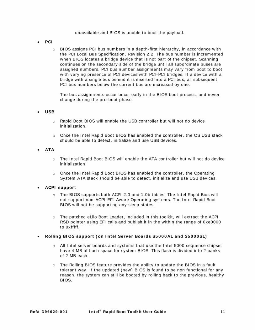
unavailable and BIOS is unable to boot the payload.
• PCI
o BIOS assigns PCI bus numbers in a depth-first hierarchy, in accordance with the PCI Local Bus Specification, Revision 2.2. The bus number is incremented when BIOS locates a bridge device that is not part of the chipset. Scanning continues on the secondary side of the bridge until all subordinate buses are assigned numbers. PCI bus number assignments may vary from boot to boot with varying presence of PCI devices with PCI-PCI bridges. If a device with a bridge with a single bus behind it is inserted into a PCI bus, all subsequent PCI bus numbers below the current bus are increased by one.
The bus assignments occur once, early in the BIOS boot process, and never change during the pre-boot phase.
• USB
o Rapid Boot BIOS will enable the USB controller but will not do device initialization.
o Once the Intel Rapid Boot BIOS has enabled the controller, the OS USB stack should be able to detect, initialize and use USB devices.
• ATA
o The Intel Rapid Boot BIOS will enable the ATA controller but will not do device initialization.
o Once the Intel Rapid Boot BIOS has enabled the controller, the Operating System ATA stack should be able to detect, initialize and use USB devices.
• ACPI support
o The BIOS supports both ACPI 2.0 and 1.0b tables. The Intel Rapid Bios will not support non-ACPI-EFI-Aware Operating systems. The Intel Rapid Boot BIOS will not be supporting any sleep states.
o The patched eLilo Boot Loader, included in this toolkit, will extract the ACPI RSD pointer using EFI calls and publish it in the within the range of 0xe0000 to 0xfffff.
• Rolling BIOS support (on Intel Server Boards S5000AL and S5000SL)
o All Intel server boards and systems that use the Intel 5000 sequence chipset have 4 MB of flash space for system BIOS. This flash is divided into 2 banks of 2 MB each.
o The Rolling BIOS feature provides the ability to update the BIOS in a fault tolerant way. If the updated (new) BIOS is found to be non functional for any reason, the system can still be booted by rolling back to the previous, healthy BIOS.
Ref# D96629-001 Intel® Rapid Boot Toolkit User Guide 11

• Front Panel
o In DP systems, the platform supports a power button, a reset button, and an NMI button on the control panel.
• The BIOS supports the front control panel power button. Pressing the power button initiates a request that the BMC forwards to the ACPI power state machines in the chipset. It is monitored by the BMC and does not directly control power on the power supply.
• Pressing the platform reset button initiates a request that is forwarded by the BMC to the chipset. The BIOS does not affect the behavior of the reset button.
• The BIOS supports the front control panel NMI button. The NMI button may not be provided on all front panel designs. Pressing the NMI button initiates a request that causes the BMC to generate an NMI (non-maskable interrupt). The NMI is captured by the BIOS during boot services time, and by the operating system during Runtime. During boot services time, the BIOS halts the system upon detection of the NMI.
o In UP systems, the platform supports a power button and a reset button.
• The BIOS supports a front control panel power button. Pressing the power button initiates a request to the chipset.
• The platform supports a front control panel reset button. Pressing the reset button initiates a request to the chipset.
• Console Redirection
o BIOS supports redirection of both video and keyboard via a serial link (serial port). When console redirection is enabled, the keyboard input and console output are passed to the remote console through the serial link.
o To use console redirection the user has to configure the Console redirection parameters such as Baud Rate, Flow control, Terminal Type and the port number. This can be done through the Intel SysCfg utility.
o The Intel Rapid Boot BIOS will not support redirection of Legacy Consoles.
What’s not in the BIOS? The Intel Rapid Boot BIOS speeds-up the boot time and frees-up space in the BIOS flash by cutting down on features that do not add value in the HPC environment.
The features that the Intel Rapid Boot BIOS does not support include:
• Processor RAS (Reliability, Availability and Serviceability)
o Intel Rapid Boot BIOS will not report an error if mixed processor families, mixed FSB speeds or mixed processor cache sizes are used. The system behavior is unpredictable under such circumstances.
12 Intel® Rapid Boot Toolkit User Guide Ref# D96629-001

• Hyper-Threading Technology (HT Technology)
o The Intel Rapid Boot BIOS will not support HT Technology.
• Enhanced Intel SpeedStep® Technology
o Enhanced Intel SpeedStep® Technology enables decreased average power consumption and decreased average heat production by dynamically adjusting processor voltage and core frequency.
o The Intel Rapid Boot BIOS will not support Enhanced Intel SpeedStep® Technology.
• Intel Virtualization Technology (Intel VT)
o The Intel Rapid Boot BIOS will not support Intel VT.
o Inside a Payload, Intel VT can be enabled by sending a VMXON instruction to each of the cores.
• BIOS Setup Screen
o The Intel Rapid Boot BIOS will not support the BIOS setup screen.
o BIOS configuration should be done using the Intel SysCfg tool.
• Boot Device Selection (BDS)
o The Intel Rapid Boot BIOS will not support Boot Device Selection. The BIOS will always boot the payload embedded in Flash.
o Boot Device Selection can be done in the payload using open source tools like Kboot.
• Memory
o The Intel Rapid Boot BIOS will not support Memory RAS (Reliability, Availability and Serviceability) features like error correcting code, sparing and mirroring.
• Snoop Filter
o The Intel Rapid Boot BIOS will not support Snoop Filter.
• Acoustics
o The Intel Rapid Boot BIOS will not be issuing any commands to the BMC through out its life cycle. Hence BIOS will not be updating the Tcontrol offset and Tcontrol base required to calculate and regulate the fan speed. BMC will take its default Tcontrol base and Tcontrol offset to control and regulate the fan speed.
• Secure Mode – Admin and User passwords
o The Intel Rapid Boot BIOS will not support BIOS Admin and User passwords.
Ref# D96629-001 Intel® Rapid Boot Toolkit User Guide 13

• Option ROMs
o The Intel Rapid Boot BIOS will not execute Option ROMs. An important impact due to this will be the lack of Video support.
o For devices like SCSI, NIC and RAID, the payload kernel (if support is added) will execute the option ROMs.
• SMBIOS Tables
o The Intel Rapid Boot BIOS will not support SMBIOS Tables.
o Newer Kernels may flag an ACPI blacklist error if SMBIOS Type 0 is not available. Give an “acpi=force” kernel boot parameter to override this check.
• BIOS messages in System Event Log
o The Intel Rapid Boot BIOS will not support logging BIOS messages in the System Event Log.
• BIOS – BMC Communication
o The Intel Rapid Boot BIOS will not support BIOS – BMC communication.
o BMC is present only in DP platforms.
• Intel Active Management Technology (Intel AMT)
o The Intel Rapid Boot BIOS will not support the Intel AMT GUI on Intel Server Boards S3000AH and S3000PT.
o Once Intel AMT is configured in the normal production BIOS, and the system shifts to an Intel Rapid Boot BIOS, remote access using Intel AMT APIs will continue to work.
14 Intel® Rapid Boot Toolkit User Guide Ref# D96629-001

55 Payload Creation Payload CreationYou can use the Payload Tool Chain to create capsule files from a bzImage and Initrd which can then be flashed using the pyFlash tool.
During the payload creation process, eLilo is statically linked against the kernel and Initramfs or initrd (by generating header files from the binary images) to generate the eLinux.efi binary. From eLinux.efi, using the CIT tools, we get a capsule file.
The Toolkit user must identify the kernel, build the kernel image, and generate an initrd. Once this is done, these images must be placed inside the payload directory of the payload tool chain.
Issue a make clean command followed by a make command to generate two capsule files (one for DP and one for UP) inside the current directory. This can now be flashed using pyFlash to put the kernel in the flash area.
Note: The EFI Memory Map (published by the Rapid Boot BIOS) gets overwritten by the Linux kernel while uncompressing the initrd. There is a patch for this (against the 2.6.18 kernel) in the samples/payloads/patches folder. This patch must be applied to all payloads.
Ref# D96629-001 Intel® Rapid Boot Toolkit User Guide 15

16 Intel® Rapid Boot Toolkit User Guide Ref# D96629-001

66 Sample Payloads Sample PayloadsThe payload is an EFI object file which combines an EFI bootable Operating System (a minimal kernel and a file system) and a boot loader. The Intel Rapid Boot Toolkit includes two example payloads: a generic example payload; and a launcher payload. Familiarity with Linux is recommended in order to understand the example payload flow.
The example payloads are included to serve as a starting point for toolkit users. New users should start by flashing the Intel Rapid Boot BIOS and the generic payload. This should be followed by re-creating the generic payload (using instructions below) to get a better understanding of the payload creation process. Sources are provided for the bzImage (.config) and initrd for both the payloads.
Once the user is familiar with the payload creation and installation process, the user can begin making payloads that solve their business needs.
Note: By design, Rapid Boot BIOS does not support SMBIOS tables. In Linux Kernel versions 2.6.17 and above, this will trigger an ACPI blacklist panic while booting through kexec. An acpi=force kernel parameter will force the kernel to ignore this and continue booting (with ACPI subsystem initialized).
Generic Payload Generic Payload is an example payload packaged along with the toolkit. It has support for the Intel Gigabit 1000 network controller with support for integrated EFI boot, ACPI 2.0, NFS, SATA, Proc/Sys filesystem, EXT3 and Kexec. The initrd includes a ssh server (Drop Bear), busy box shell, kboot, proc file system, dhcp client, chroot and other commands (see full list below).
The .config used for building the generic example kernel is present in the src directory of generic payload. The kboot patches are also present in the same directory.
At the end of the boot process, the generic payload picks up its IP and the NFS server address from the dhcp server (a sample dhcp configuration is documented in the appendix) on the NIC1 port. The NFS location, /nfs/, is mounted. The payload then searches for a /payload/<IP> directory. If found and an executable payload.sh is present inside this directory, it is executed. Otherwise payload searches for an executable payload.sh script within the main payload directory. If found this script is executed.
If the payload is not able to find the script, then it boots to a kboot prompt. Applications must be executed from the shell prompt (and not from the kboot prompt).
Commands supported by Generic Payload The commands supported are listed below.
ash
bunzip2
busybox
bzcat
cat
chroot
cp
date
dd
df
du
echo
Ref# D96629-001 Intel® Rapid Boot Toolkit User Guide 17

env loadkmap reboot test
expr ls rm tftp false md5sum rmdir touch
fdisk mkdir route true free mknod sh udhcpc
gunzip more sha1sum umount halt mount sort uname
head mv switch_root wc hwclock ping sync wget
ifconfig pivot_root tail which
ln poweroff tar zcat
How To Build the Generic Payload
Use the following procedure to build the Generic payload.
Note
Compilation will take approximately 15 minutes (varies with your system's configuration).
Compilation will involve downloading of files from the internet. Approximately 100 MB disk space will be needed for the downloaded files and a further 500 MB will be needed during the Compilation process.
1. Copy the samples/payloads/generic-payload/src/kboot-10-generic-kernel-config as samples/payloads/kboot/kboot-10/config/kernel-config. a) Kboot will attempt to download the following files if you issue make:
i. binutils-2.16.1.tar.bz2 ii. busybox-1.1.1.tar.bz2 iii. busybox-1.2.2.tar.bz2 iv. dropbear-0.48.1.tar.gz v. gcc-core-3.4.6.tar.bz2 vi. gcc-core-4.0.3.tar.bz2 vii. kbd-1.12.tar.gz viii. kexec-tools-1.101.tar.gz ix. lilo-22.7.3.src.tar.gz x. linux-2.6.16.1.tar.bz2 xi. linux-2.6.18.tar.bz2 xii. uClibc-0.9.28.tar.bz2 xiii. udev-088.tar.bz2
b) If you want to avoid this (for example, if your corporate firewall blocks the download), do the following:
i. Create the samples/payloads/kboot/kboot-10/dl folder if necessary. Manually download the files from the respective websites and place them in the samples/payloads/kboot/kboot-10/dl folder.
18 Intel® Rapid Boot Toolkit User Guide Ref# D96629-001

ii. Create an .ok file for each of these by touching it. For example: For binutils-2.16.1.tar.bz2, use the command, touch binutils-2.16.1.tar.bz2.ok
2. Empty the samples/payloads/kboot/patches/kboot-10/ directory if present. If not present, create it.
3. Copy the samples/payloads/generic-payload/src/kboot-10-patches-generic.tar.gz to the samples/payloads/kboot/patches/kboot-10/ directory.
Change directory to samples/payloads/kboot/patches/kboot-10/ directory. Extract the kboot-10-patches-generic.tar.gz inside the current directory. These patches modify the kboot build environment before the build process starts.
Kernel patches must be copied to samples/payloads/kboot/kboot-10/patches folder. The name of the patch must be in the form *kernel*.patch
Two kernels patches are part of the toolkit.
- The EFI Memory Map (published by the Rapid Boot BIOS) gets overwritten by the Linux kernel while uncompressing the initrd. There is a patch for this (against the 2.6.18 kernel) in the samples/payloads/patches folder.
This patch must be applied for all payloads. Copy the patch to the samples/payloads/kboot/kboot-10/patches.
- The SMI driver patch is needed for the Intel SysCfg utility to communicate with
BIOS in the Linux environment. The SMI driver patch is present in samples/payloads/generic-payload/src directory.
This patch is applicable for all payloads in which the Intel Syscfg utility is expected to be run. If applicable, copy the patch to the samples/payloads/kboot/kboot-10/patches.
4. Go to samples/payloads/kboot/, issue the make clean command first and then make.
5. Answer the questions asked by kboot as follows: a) No config/fstab. Use /etc/fstab (and copy to config/fstab) ? [Y/n] n b) Access configuration files on root file system ? [Y/n] n c) Enable TCP/IP networking ? [Y/n] y d) Configure IP addresses with DHCP ? [y/n] y e) Also configure a static IP address, as fallback ? [y/N] n f) Allow outbound SSH ? [Y/n] n g) Allow inbound SSH ? [y/n] y h) Copy host key(s) from /etc/ssh/ ? [y/N] y i) Support NFS-mounting ? [Y/n] y
Ref# D96629-001 Intel® Rapid Boot Toolkit User Guide 19

The bzImage and initrd will be ready in the current folder.
6. Copy the bzImage and initrd to the tools/payload-tool-chain/payload folder.
A sample cmdline file is already present in this directory.
7. Go to tools/payload-tool-chain directory and issue make.
The capsule files (DP_Payload.Cap and UP_Payload.Cap) will be ready in the current folder.
Launcher Payload Intel Rapid Boot BIOS will initialize the USB controller but will not do device detection. The Launcher payload can be put in Flash which has a Linux kernel with USB drivers compiled in. The Launcher payload, at the end of the boot process, will launch the user’s payload from the USB/SATA device.
Modes of Operation
The USB payload launcher is controlled by a configuration file (/etc/payload.conf). There are two modes of operation: direct mode and scan mode.
Direct mode
In direct mode, the configuration file will specify the device and absolute path of the kernel and initrd. If the direct mode boot path fails, the system will revert to scan mode.
Scan mode
All USB storage devices in the system will be detected using the following algorithm:
1. One device at a time, the partitions are scanned in sequence looking for the grub configuration file (/boot/grub/menu.lst or /grub/menu.lst). If the grub configuration file is found, the default choice is picked up and kernel is loaded via a kexec call.
2. If grub configuration file is not found, then the partitions are scanned in sequence looking for the bzImage and initrd in a pre-determined folder (/boot/payload). Once the bzImage and initrd are detected, the payload will do a kexec call to launch this kernel.
3. If no payload is detected, the intermediate payload will look for SATA devices and repeat the process.
4. If a boot path is not detected even after this, the system sleeps for a brief period and repeats the process.
In scan mode, a USB device can be hot plugged. The device will be detected in the next iteration and the payload will be booted.
How To Build the Launcher Payload
Use the following procedure to build the Launcher payload.
20 Intel® Rapid Boot Toolkit User Guide Ref# D96629-001

Note
Compilation will take approximately 15 minutes (varies with your system's configuration).
Compilation will involve downloading of files from the internet. Approximately 100 MB disk space will be needed for the downloaded files and a further 500 MB will be needed during the Compilation process.
1. Copy the samples/payloads/launcher-payload/src/kboot-10-launcher-kernel-config as samples/payloads/kboot/kboot-10/config/kernel-config. a) Kboot will attempt to download the following files if you issue make:
i. binutils-2.16.1.tar.bz2 ii. busybox-1.1.1.tar.bz2 iii. busybox-1.2.2.tar.bz2 iv. dropbear-0.48.1.tar.gz v. gcc-core-3.4.6.tar.bz2 vi. gcc-core-4.0.3.tar.bz2 vii. kbd-1.12.tar.gz viii. kexec-tools-1.101.tar.gz ix. lilo-22.7.3.src.tar.gz x. linux-2.6.16.1.tar.bz2 xi. linux-2.6.18.tar.bz2 xii. uClibc-0.9.28.tar.bz2 xiii. udev-088.tar.bz2
b) If you want to avoid this (for example, if your corporate firewall blocks the download), do the following:
i. Create the samples/payloads/kboot/kboot-10/dl folder if necessary. Manually download the files from the respective websites and place them in the samples/payloads/kboot/kboot-10/dl folder.
ii. Create an .ok file for each of these by touching it. For example: For binutils-2.16.1.tar.bz2, use the command, touch binutils-2.16.1.tar.bz2.ok
2. Empty the samples/payloads/kboot/patches/kboot-10/ directory if present. If not present, create it.
3. Copy the samples/payloads/launcher-payload/src/kboot-10-patches-launcher.tar.gz to the samples/payloads/kboot/patches/kboot-10/ directory.
Change directory to samples/payloads/kboot/patches/kboot-10/ directory. Extract the kboot-10-patches-launcher.tar.gz inside the current directory. These patches modify the kboot build environment before the build process starts.
Ref# D96629-001 Intel® Rapid Boot Toolkit User Guide 21

Kernel patches must be copied to samples/payloads/kboot/kboot-10/patches folder. The name of the patch must be in the form *kernel*.patch
Two kernels patches are part of the toolkit.
- The EFI Memory Map (published by the Rapid Boot BIOS) gets overwritten by the Linux kernel while uncompressing the initrd. There is a patch for this (against the 2.6.18 kernel) in the samples/payloads/patches folder.
This patch must be applied for all payloads. Copy the patch to the samples/payloads/kboot/kboot-10/patches.
- The SMI driver patch is not applicable for the launcher payload.
4. Go to samples/payloads/kboot/, issue the make clean command first and then make.
5. Answer the questions asked by kboot as follows:
i. No config/fstab. Use /etc/fstab (and copy to config/fstab) ? [Y/n] n
ii. Access configuration files on root file system ? [Y/n] n The bzImage and initrd will be ready in the current folder.
6. Copy bzImage and initrd to the tools/payload-tool-chain/payload folder.
A sample cmdline file is already present in this directory.
7. Go to tools/payload-tool-chain directory and issue make.
The capsule files (DP_Payload.Cap and UP_Payload.Cap) will be ready in the current folder.
22 Intel® Rapid Boot Toolkit User Guide Ref# D96629-001

77 The Tools The Tools
Intel® One Boot Flash Update The Intel® One Boot Flash Update (Intel® OFU) Utility updates the System BIOS, Baseboard Management Controller (BMC) firmware, Hot-swap Controller (HSC) firmware, Field Replaceable Unit firmware, and Sensor Data Record (SDR) firmware on the Intel server while the operating system is running. The utility is launched from a command prompt in the operating system. This utility can also update the optional Intel® Remote Management Module (Intel® RMM) firmware on Quad-Core Intel® Xeon® and Dual-Core Intel® Xeon® processor-based servers from Intel.
The BMC boot block, Intel® Local Control Panel, HSC, and FRU updates take effect immediately when the utility executes. The System BIOS, BMC Op Code, sensor data records (SDRs), and BMC Platform Information Area (PIA) updates are programmed into their respective secondary flash areas and the utility sets an internal flag in the BIOS and BMC to indicate that the update occurred. After a system reset, the newer version of the System BIOS, BMC, and SDRs are validated and activated.
This utility can be executed remotely through a secure network connection using a Telnet Client and Terminal Services in Windows* or using a Telnet Client and Remote Shell under Linux.
A special statically linked version of Intel OFU has been packaged along with the toolkit to ensure it will work in environments like the generic payload where the system shared libraries are not available.
Intel OFU requires production BIOS Version R0050 and above for Intel Server Board S5000AL and S5000SL, and R39 and above for Intel Server Boards S3000AH and S3000PT. To move from a version lower than R39 to R39, use the iFlash tool packaged with the production BIOS package.
Intel OFU requires Rapid Boot BIOS Version R02 and above for Intel Server Boards S5000AL and S5000SL and R03 and above for Intel Server Boards S3000AH and S3000PT.
Intel OFU requires BMC version 56 or above for Intel Server Boards S5000AL and S5000SL.
Please refer to the Intel One Boot Flash Update Utility User Guide for more details on usage.
Sample Intel® OFU Configuration File
The Intel OFU utility is driven by a configuration file. A sample configuration file which does BIOS, BMC and FRUSDR update is shown below. The BMC and FRUSDR updates are conditional and are only performed if the BMC exists.
Ref# D96629-001 Intel® Rapid Boot Toolkit User Guide 23
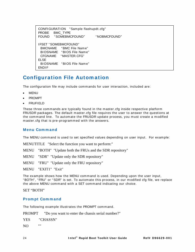
CONFIGURATION "Sample flashupdt.cfg" PROBE BMC_TYPE FOUND “SOMEBMCFOUND” “NOBMCFOUND”
IFSET “SOMEBMCFOUND” BMCNAME “BMC File Name” BIOSNAME “BIOS File Name” CFGNAME “MASTER.CFG” ELSE BIOSNAME “BIOS File Name” ENDIF
Configuration File Automation
The configuration file may include commands for user interaction, included are:
• MENU
• PROMPT
• FRUFIELD
These three commands are typically found in the master.cfg inside respective platform FRUSDR packages. The default master.cfg file requires the user to answer the questions at the command line. To automate the FRUSDR update process, you must create a modified master.cfg that is pre-programmed with the answers.
Menu Command
The MENU command is used to set specified values depending on user input. For example:
MENUTITLE "Select the function you want to perform:"
MENU "BOTH" "Update both the FRUs and the SDR repository"
MENU "SDR" "Update only the SDR repository"
MENU "FRU" "Update only the FRU repository"
MENU "EXIT1" "Exit"
The example shows how the MENU command is used. Depending upon the user input, “BOTH”, “FRU” or “SDR” is set. To automate this process, in our modified cfg file, we replace the above MENU command with a SET command indicating our choice.
SET “BOTH”
Prompt Command
The following example illustrates the PROMPT command.
PROMPT "Do you want to enter the chassis serial number?"
YES "CHASSN"
NO ""
24 Intel® Rapid Boot Toolkit User Guide Ref# D96629-001

To automate this process, in our modified cfg file, we replace the above PROMPT command with a SET command indicating our choice.
SET “CHASSN”
Frufield Command
The following example illustrates the FRUFIELD command:
FRUFIELD "S#" "@STDIN:ASCII" // Enter Chassis Serial Number
To automate this process, in our modified cfg file, we replace the above FRUFIELD command with the following one which tells Intel OFU to pick the answer from a FILE instead of STDIN,
FRUFIELD "S#" "@FILE:ASCII:answers.txt:1" // Enter Chassis Serial Number
Other redirection options include environmental variables (containing the value or the name of the file to pick the value from).
RMM Update Automation
When an RMM update is tried via the Intel OFU configuration file, it will prompt for a username or password. This makes it unsuitable for job distribution mechanisms where user interaction is not possible.
In such situations, the mmconfig tool (part of the Intel OFU package) can be invoked directly using the following syntax:
mmconfig –u <username> –p <password> -f <filename>
Intel® System Configuration Utility (SysCfg) The Intel SysCfg utility is a command-line utility that can be used to save and restore BIOS and firmware settings to a file, or to set and display individual settings. Intel SysCfg may be used in a script to automate the process of configuring multiple servers.
The general syntax is:
syscfg [{/|-}command [arguments]] […next_command [arguments]]
Multiple commands may be specified on a single line unless otherwise noted in the Command Reference description. The maximum line length is 127 characters.
A special statically linked version of Intel SysCfg has been packaged along with the toolkit to ensure in environments like the generic payload where the system shared libraries are not available.
Please refer to the Intel System Configuration Utility User Guide for more details on usage.
Ref# D96629-001 Intel® Rapid Boot Toolkit User Guide 25
SMI Driver
The SysCfg utility uses the System Management Interrupt (SMI) to communicate with BIOS in the Linux environment. For this, SysCfg uses an SMI driver whose sources are packaged along with the toolkit.
The Generic payload has the SMI module already inserted. Users interested in using SysCfg in a different environment need to compile the driver and insert the driver.
Kernel headers must already be installed. Kernel documentation should be consulted for understanding the gcc dependency.
The <toolkit>/tools/SysCfg/src/driver/ directory has the sources. Kernel headers must already be installed. A make will generate smi.ko which should be inserted (insmod smi.ko). A dmesg will give the mknod command which needs to be executed.
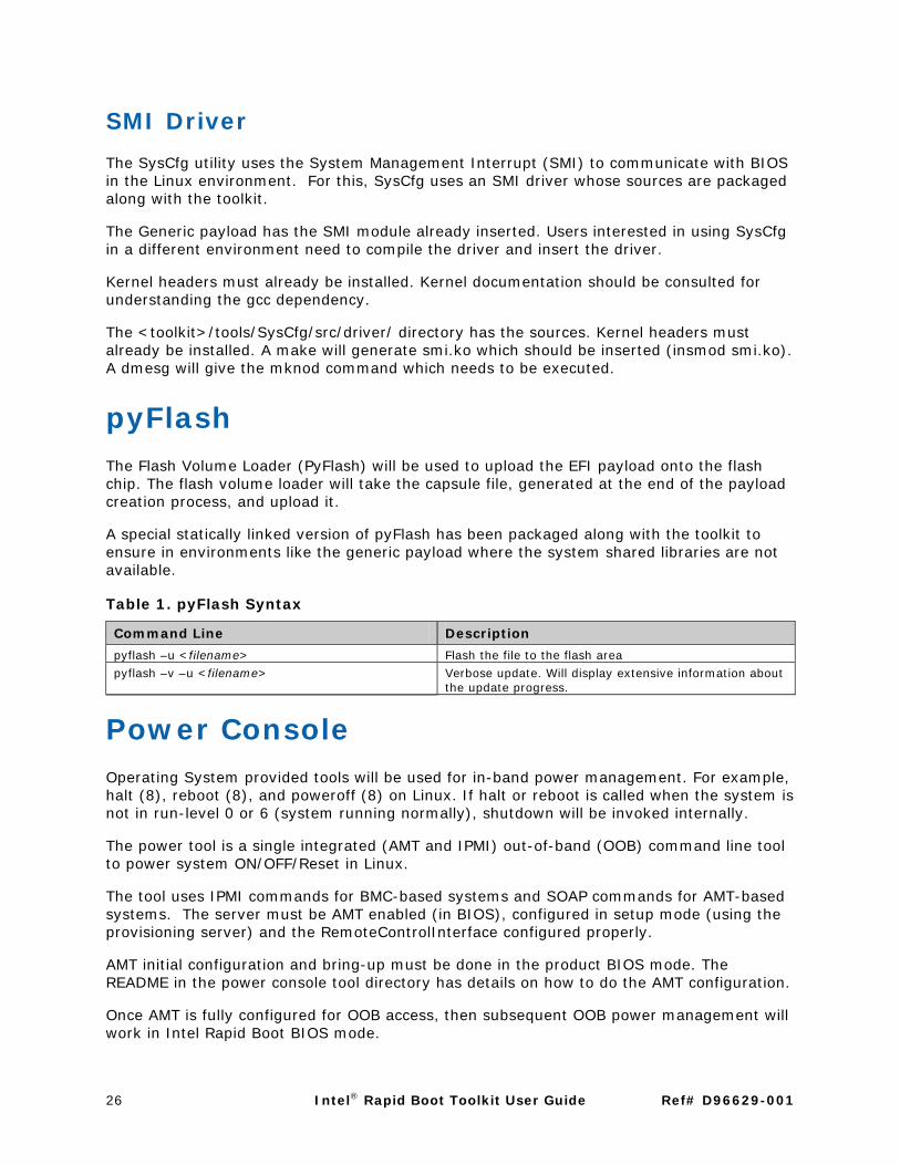
pyFlash The Flash Volume Loader (PyFlash) will be used to upload the EFI payload onto the flash chip. The flash volume loader will take the capsule file, generated at the end of the payload creation process, and upload it.
A special statically linked version of pyFlash has been packaged along with the toolkit to ensure in environments like the generic payload where the system shared libraries are not available.
Table 1. pyFlash Syntax
Command Line Description
pyflash –u <filename> Flash the file to the flash area
pyflash –v –u <filename> Verbose update. Will display extensive information about the update progress.
Power Console Operating System provided tools will be used for in-band power management. For example, halt (8), reboot (8), and poweroff (8) on Linux. If halt or reboot is called when the system is not in run-level 0 or 6 (system running normally), shutdown will be invoked internally.
The power tool is a single integrated (AMT and IPMI) out-of-band (OOB) command line tool to power system ON/OFF/Reset in Linux.
The tool uses IPMI commands for BMC-based systems and SOAP commands for AMT-based systems. The server must be AMT enabled (in BIOS), configured in setup mode (using the provisioning server) and the RemoteControlInterface configured properly.
AMT initial configuration and bring-up must be done in the product BIOS mode. The README in the power console tool directory has details on how to do the AMT configuration.
Once AMT is fully configured for OOB access, then subsequent OOB power management will work in Intel Rapid Boot BIOS mode.
26 Intel® Rapid Boot Toolkit User Guide Ref# D96629-001

Note
You must wait for a minimum of 15 seconds before issuing consecutive power commands (on/off/reset/status).
Table 2. power Syntax
Command Line Description
power -ip <ip[:port]> -user <username> -password <password> -operation on e.g. power –ip 10.224.210.15:16992 –user admin -password intel123 –operation on
Out-of-band power on
power -ip <ip[:port]> -user <username> -password <password> -operation off e.g. power –ip 10.224.210.15:16992 –user admin -password intel123 –operation off
Out-of-band power off
power -ip <ip[:port]> -user <username> -password <password> -operation reset e.g. power –ip 10.224.210.15:16992 –user admin -password intel123 –operation reset
Out-of-band power reset
power -ip <ip[:port]> -user <username> -password <password> -operation status e.g. power –ip 10.224.210.15:16992 –user admin -password intel123 –operation status
Out-of-band power status
jQ (Simple Job Queuing)
The toolkit includes a simple job queuing implementation which will help to get started on job queuing.
The job client downloads job information (and any needed collateral) from a NFS mounted priority job queue, executes the job and stores the result in the same location. The job could be a system update package along with Intel OFU, Intel SysCfg or even a Linux kernel (which is booted using Kboot) providing a full Linux environment for specialized operations.
The priority queue is a flat file, internally represented as a sqlite3 database. The table definition for a job would include an ID, an owner (the IP identifying the target for the job), the state (waiting, pending and completed), timestamps (for when the job was submitted, started and finished), the path (from where to pick up the executable) and the command line (with arguments). The two tools that are the primary interfaces into the priority queue are: an administrative tool (Qadmin), and a job client (Qfeed).
The Qadmin tool support operations for submitting jobs, displaying current status information for the jobs and other relevant tasks. Qfeed when launched, will poll the NFS mounted priority queue for jobs (for which it is set as the owner), execute them, and then store the results in the NFS location.
The job queuing implementation will not support interactive jobs.
Ref# D96629-001 Intel® Rapid Boot Toolkit User Guide 27

Table 3. Priority Queue Schema
Element Description
ID Job ID
Owner IP of the owner of the job. If this is set to 0.0.0.0, then it is an un-targeted job. Anyone can pick it up and execute it
State Current state of the job. Possible values:
Waiting Pending Completed
Submitted Time when the job was submitted
Started Time when the job execution was started
Finished Time when the job execution was finished
Path Path from where to pick the job
Command The job command
Stdout The output of the job
Stderr Error output of the job
Qadmin Usage
Note
The option selector in all commands below uses double hyphens (--).
Table 4. qadmin Syntax
Command Line Description
qadmin --create <job queue name> e.g. qadmin --create q
This command will create a new job queue at the specified location.
qadmin --queue <job queue name> --list e.g. qadmin --queue q --list
This command will list status information of jobs present in the job queue q.
qadmin --queue <job queue name> --add <IP or 0.0.0.0> <directory> “path to executable with command line options” e.g. qadmin --queue q --add 0.0.0.0 /files “./flashupdt –u master.cfg”
This command will add a job to the job queue q.
Qfeed Usage
Table 5. qfeed Syntax
Command Line Description
qfeed --queue <job queue name> --output <output directory> --delay <poll delay> e.g. qfeed --queue q --output /files/output --delay 10
This command will fetch a job from the queue every n seconds and execute the job.
28 Intel® Rapid Boot Toolkit User Guide Ref# D96629-001

88 Glossary GlossaryAcronym or Term Definition
BMC Baseboard Management Controller FRU Field Replaceable Unit SDR Sensor Data Record IPMI Intelligent Platform Management Interface UP Uni Processor DP Dual Processor SMI System Management Interrupt HPC/HDC cluster A collection of servers interconnected by a local high-speed
network. Compute node A single server in the HPC/HDC cluster, which will execute compute
jobs or provide other support services to the HPC/HDC cluster. Management console
The computer node of the HPC/HDC cluster which provides centralized management. The entire HPC/HDC cluster is managed via the management console, with a single coherent view of the cluster. On a HPC cluster, this capability may be provided on the “head node.”
HPC/HDC provisioning bootstrap
The combination of the Intel Rapid Boot Toolkit BIOS and the Payload.
Embedded Operating System
Intel Rapid Boot Toolkit Payload is Operating System agnostic. This could be a light weight Linux kernel, Win PE or any other customer preferred Operating System.
Deep Boot Conventional BIOS boot, as implemented in Intel Server products, where extensive board configuration, initialization, and diagnostics are performed, before any Operating System boot occurs.
Shallow Boot Early redirection of the BIOS boot process, after CPU, memory, and chipset initialization, to load an EFI Payload. See also Deep Boot.
Intel Rapid Boot BIOS
The board BIOS shipped to the OEM vendor, exclusive of 3rd-party code. The Intel Rapid Boot Toolkit BIOS is derived from an APTIO code base, and has the added ability to redirect the boot process at an early stage to an EFI Payload, either from Flash ROM, or from a USB based device (using an intermediate payload). This redirection path is called “shallow boot.”
“pre-boot” A bit of a misnomer, the term is used to denote the interception of boot via the shallow boot path, allowing the customer/end user to insert functionality in a manner analogous to extending the BIOS. For a “normal” scenario, one might catch the platform exiting the shallow boot path, boot a payload containing an Operating System running a queuing client, and have the queuing client actually load the “post-boot” operating system. Thus the “pre-boot”
Ref# D96629-001 Intel® Rapid Boot Toolkit User Guide 29

Acronym or Term Definition
environment will generally run a purposed Operating System package, rather than a general purpose Operating System. Another definition might be “after BIOS, before operational mode”.
30 Intel® Rapid Boot Toolkit User Guide Ref# D96629-001

99 Tips and Tricks Tips and Tricks
Quick Start Guide The recommended sequence for someone new to the toolkit is:
1. Read this User Guide.
2. Flash the Intel Rapid Boot BIOS and the Generic Payload Capsule.
• Intel OFU can be used to flash the Intel Rapid Boot BIOS. Intel OFU is driven by a configuration file. A sample configuration file can be found in the Intel OFU section of this document. A single command BIOSNAME with the file name will suffice for a BIOS update operation.
• Immediately after the BIOS update, a payload upload should be done with the pyFlash utility.
3. Try out various commands with the kboot shell prompt in Generic Payload. For example, try a kexec call to launch a second stage kernel from a network location.
4. Re-create the Generic Payload using the instructions in Section 6, “Sample Payloads.”
Payload Development While developing payloads, Intel recommends using the Launcher Payload along with the bzImage and initrd in a USB device. This ensures that the system will not be rendered unusable if the payload does not boot for some reason.
While developing payloads, where possible, use Intel Server Board S5000AL or S5000SL. These server boards have an additional layer of security called the “rolling BIOS” support which gives the ability to switch BIOS banks (with the recovery jumper (J3H1)) if one of the banks has a payload which will not boot. This feature was described in a previous section.
Ref# D96629-001 Intel® Rapid Boot Toolkit User Guide 31

32 Intel® Rapid Boot Toolkit User Guide Ref# D96629-001

A. Appendix
Linux* Compilation The Linux kernel sources can be downloaded from http://kernel.org.
The first step in the kernel compilation process is typically an edit of the default Makefile to change the EXTRAVERSION variable to a meaningful value.
The kernel make process is controlled by the .config file. In a typical scenario, one would copy over an existing .config file, make the required changes and save back. While using the Intel Rapid Boot Toolkit, using a standard .config file may not be of much use (as one would have to deselect most options to generate a minimal kernel). The package has the .config files used for building the generic as well as the launcher payloads. These can be found inside the respective src directories inside samples/payloads. These can serve as a good starting point.
The make configuration process is menu driven and can be started with make menuconfig. An ncurses based front-end will be launched which takes the user through a series of screens, each prompting for the user’s interest in particular features.
The different subsections include:
• Code maturity level options – This is where all the experimental features go in. • General setup – General setup like System V IPC, Message queues, Kernel .config
support can be configured using this screen. • Loadable module support – Using this screen, one can turn on/off loadable module
support. • Block layer – This screen controls the support of large block devices, support for large
single files, IO schedulers etc • Processor type and features – One can fine tune the processor support of the kernel
using this screen. • Power management options (ACPI, APM) – This screen controls power management
support in the kernel. • Bus options (PCI, PCMCIA, EISA, MCA, ISA) – This screen controls support of
system bus devices. • Executable file formats – This screen controls support of the executable file formats
supported by the kernel. • Networking – Networking support in the kernel is controlled using this screen. • Device Drivers – All device drivers configuration can be done via this screen. • File systems – Support for various file systems like ext2, ext3 and reiserfs can be
configured using this screen. • Instrumentation support – Profiling support (experimental) can be turned on using
this screen. • Kernel hacking – Kernel parameters like Kernel debugging, Debug filesystem can be
controlled using this screen. • Security options – All security options are grouped in here. • Cryptographic options – All cryptographic options are grouped in here.
Ref# D96629-001 Intel® Rapid Boot Toolkit User Guide 33

• Library routines – Various CRC routines are grouped in here.
The next step in the kernel compilation process is a make clean followed by a make bzImage to generate the compressed kernel image.
The mkinitrd utility can be used to create an initrd (initial ramdisk). Newer versions of the kernel have added support for Initramfs which is considered technically superior to initrd. Initramfs filesystem can be created using the mkinitramfs utility.
Kboot Kboot is a Linux boot loader based on the kexec system call. In Intel Rapid Boot BIOS, the BDS (the boot device selection) path is stripped down and this functionality could be added in the payload using Kboot. Kboot is a collection of shell scripts, acting as glue for various components. Kexec system call was added to the Linux 2.6 kernel providing support for loading a new kernel over a currently running one.
The kboot.conf will indicate the new kernel to be loaded along with the initrd and the command line. Busy box is a minimal shell, comprising basic utilities and linked against the uclibc libraries. DropBear is a SSH server, useful for remotely logging in and managing the node.
Kboot can be downloaded from the http://kboot.sf.net. The website has additional details about the project.
NFS Server Setup A NFS v4 server should be setup to store the tools and queue. NFS allows machines to mount a folder on a remote machine, allowing for access akin to a local folder.
NFS consists of five distinct daemons: rpc. nfsd (which is the main daemon), rpc.lockd together with rpc.statd (which implement the locking mechanisms), rpc.mountd (to support mounting), and rpc.rquotad (file quotas).
These daemons must be part of the startup scripts of the server. To verify whether these daemons are running, the rpcinfo (-p) command can be used.
The /etc/exports configuration file controls the directories which are served over NFS. A sample configuration is:
/nfs *(rw,no_root_squash,sync)
Where:
nfs is the directory which we are serving with NFS,
* indicates that all machines have access to this
rw indicates it is read write (ro can be used to indicate it is read-only)
no_root_squash indicates that the root of the client machines is treated as root on the server.
34 Intel® Rapid Boot Toolkit User Guide Ref# D96629-001
sync tells the NFS v2 server not to reply back until all the data is written (In V3, it replies back immediately with information on which data should be retained and which ones flushed out.)
Any change to /etc/exports must be followed by an exportfs -ra which makes the nfs daemon re-read the file.
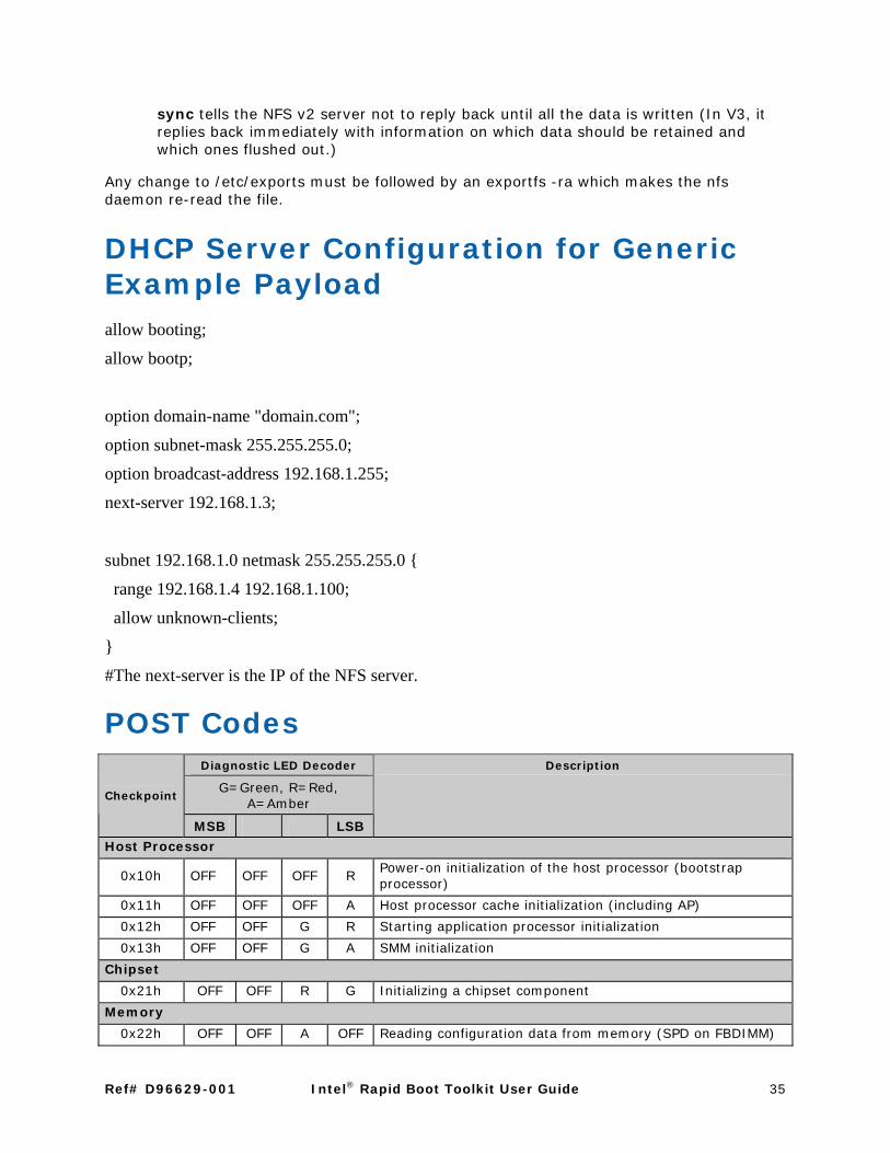
DHCP Server Configuration for Generic Example Payload allow booting;
allow bootp;
option domain-name "domain.com";
option subnet-mask 255.255.255.0;
option broadcast-address 192.168.1.255;
next-server 192.168.1.3;
subnet 192.168.1.0 netmask 255.255.255.0 {
range 192.168.1.4 192.168.1.100;
allow unknown-clients;
}
#The next-server is the IP of the NFS server.
POST Codes Diagnostic LED Decoder
G=Green, R=Red, A=Amber
Checkpoint
MSB LSB
Description
Host Processor
0x10h OFF OFF OFF R Power-on initialization of the host processor (bootstrap processor)
0x11h OFF OFF OFF A Host processor cache initialization (including AP)
0x12h OFF OFF G R Starting application processor initialization
0x13h OFF OFF G A SMM initialization
Chipset
0x21h OFF OFF R G Initializing a chipset component
Memory
0x22h OFF OFF A OFF Reading configuration data from memory (SPD on FBDIMM)
Ref# D96629-001 Intel® Rapid Boot Toolkit User Guide 35

Diagnostic LED Decoder
G=Green, R=Red, A=Amber
Description
Checkpoint
MSB LSB
0x23h OFF OFF A G Detecting presence of memory
0x24h OFF G R OFF Programming timing parameters in the memory controller
0x25h OFF G R G Configuring memory parameters in the memory controller
0x26h OFF G A OFF Optimizing memory controller settings
0x27h OFF G A G Initializing memory, such as ECC init
0x28h G OFF R OFF Testing memory
PCI Bus
0x50h OFF R OFF R Enumerating PCI busses
0x51h OFF R OFF A Allocating resources to PCI busses
0x52h OFF R G R Hot Plug PCI controller initialization
0x53h OFF R G A Reserved for PCI bus
0x54h OFF A OFF R Reserved for PCI bus
0x55h OFF A OFF A Reserved for PCI bus
0x56h OFF A G R Reserved for PCI bus
0x57h OFF A G A Reserved for PCI bus
USB
0x58h G R OFF R Resetting USB bus
0x59h G R OFF A Reserved for USB devices
ATA / ATAPI / SATA
0x5Ah G R G R Resetting PATA / SATA bus and all devices
0x5Bh G R G A Reserved for ATA
SMBUS
0x5Ch G A OFF R Resetting SMBUS
0x5Dh G A OFF A Reserved for SMBUS
Local Console
0x70h OFF R R R Resetting the video controller (VGA)
0x71h OFF R R A Disabling the video controller (VGA)
0x72h OFF R A R Enabling the video controller (VGA)
Remote Console
0x78h G R R R Resetting the console controller
0x79h G R R A Disabling the console controller
0x7Ah G R A R Enabling the console controller
Keyboard (PS2 or USB)
0x90h R OFF OFF R Resetting the keyboard
0x91h R OFF OFF A Disabling the keyboard
0x92h R OFF G R Detecting the presence of the keyboard
0x93h R OFF G A Enabling the keyboard
0x94h R G OFF R Clearing keyboard input buffer
0x95h R G OFF A Instructing keyboard controller to run Self Test (PS2 only)
Mouse (PS2 or USB)
36 Intel® Rapid Boot Toolkit User Guide Ref# D96629-001

Diagnostic LED Decoder
G=Green, R=Red, A=Amber
Description
Checkpoint
MSB LSB
0x98h A OFF OFF R Resetting the mouse
0x99h A OFF OFF A Detecting the mouse
0x9Ah A OFF G R Detecting the presence of mouse
0x9Bh A OFF G A Enabling the mouse
Pre-EFI Initialization (PEI) Core
0xE0h R R R OFF Started dispatching early initialization modules (PEIM)
0xE2h R R A OFF Initial memory found, configured, and installed correctly
0xE1h R R R G Reserved for initialization module use (PEIM)
0xE3h R R A G Reserved for initialization module use (PEIM)
Driver eXecution Enviornment (DXE) Core
0xE4h R A R OFF Entered EFI driver execution phase (DXE)
0xE5h R A R G Started dispatching drivers
0xE6h R A A OFF Started connecting drivers
DXE Drivers
0xE7h R A A G Waiting for user input
0xE8h A R R OFF Checking password
0xE9h A R R G Entering BIOS setup
0xEAh A R A OFF Flash Update
0xEEh A A A OFF Calling Int 19. One beep unless silent boot is enabled.
0xEFh A A A G Unrecoverable boot failure / S3 resume failure
Pre-EFI Initialization Module (PEIM) / Recovery
0x30h OFF OFF R R Crisis recovery has been initiated because of a user request
0x31h OFF OFF R A Crisis recovery has been initiated by software (corrupt flash)
0x34h OFF G R R Loading crisis recovery capsule
0x35h OFF G R A Handing off control to the crisis recovery capsule
0x3Fh G G A A Unable to complete crisis recovery.
SOAP Error Codes
Table 6. SOAP Error Codes
Error Codes Meaning
1 SOAP CLIENT FAULT
2 SOAP SERVER FAULT
3 SOAP TAG MISMATCH
4 SOAP TYPE
5 SOAP SYNTAX ERROR
6 SOAP NO TAG
7 SOAP IOB
Ref# D96629-001 Intel® Rapid Boot Toolkit User Guide 37

Error Codes Meaning
8 SOAP MUSTUNDERSTAND
9 SOAP NAMESPACE
10 SOAP USER ERROR
11 SOAP FATAL ERROR
12 SOAP FAULT
13 SOAP NO METHOD
14 SOAP GET METHOD
15 SOAP EOM
16 SOAP NULL
17 SOAP DUPLICATE ID
18 SOAP MISSING ID
19 SOAP HREF
20 SOAP UDP ERROR
21 SOAP TCP ERROR
22 SOAP HTTP ERROR
23 SOAP SSL ERROR
24 SOAP ZLIB ERROR
25 SOAP DIME ERROR
26 SOAP DIME HREF
27 SOAP DIME MISMATCH
28 SOAP DIME END
29 SOAP MIME ERROR
30 SOAP MIME HREF
31 SOAP MIME END
32 SOAP VERSION MISMATCH
33 SOAP PLUGIN ERROR
34 SOAP DATAENCODING UNKNOWN
35 SOAP REQUIRED
36 SOAP PROHIBITED
37 SOAP OCCURS
38 SOAP LENGTH
38 Intel® Rapid Boot Toolkit User Guide Ref# D96629-001