intelligent satellite teams for space · pdf fileintelligent satellite teams for space...
TRANSCRIPT

INTELLIGENT SATELLITE TEAMS FOR SPACE SYSTEMS
Final Report for the NASA Institute for Advanced Concepts Program
Contract Grant Number 07600-009 from the NASA Institute for Advanced Concepts (NIAC)through the University Space Research Association (USRA)
Principal Investigator: Dr. Mark E. Campbell ([email protected])
Co-Investigators: Dr. Karl F. Böhringer and Dr. Juris Vagners
Contributing Personnel:
Graduate Students: Joel Reiter Thomas SchetterBrian Tjaden Rob Grover
Undergraduate Students: Mark Hilstad John Kevin HalliganSeung Chung Michael PeytonDennis Titus Bill ShellGeorge Hwee Cindy Yeh
Collaborators:
The authors would also like to thank the scientists in the University of WashingtonAstronomy and Geophysics Departments for their interesting and timely discussions.

University of Washington NIAC Phase I Final Report 1Intelligent Satellite Teams (IST’s)
Abstract
This program examined the feasibility of developing of Intelligent Satellite Teams(IST’s) for complex space missions such as construction of space hardware, or Earth or spacescience. IST’s are composed of many nanosatellites (mass < 10kg) or picosatellites (mass <10g). IST development is a synergy of many disciplines, such as: intelligent control includingformation flying, collision avoidance, knowledge sharing, and adaptive reconfiguration;microtechnology including microelectromechanical systems (MEMS), microfabricated sensorsand actuators, nanotechnology, and integrated wireless communication; mission analysis – high-level planning and control of mission, satellites, and procedures. Recent rapid technologicaladvances in these fields open up exciting new possibilities for future space missions: spacescience missions such as testing gravitational variation, detecting and characterizing near-Earthasteroids and comets, and comprehensive exploration of the solar system; Earth science missionssuch as distributed measurements for assessment of climate processes. This report gives asummary of the results of a six-month study into the feasibility of IST’s, focusing on deriving thetypes of missions amenable to the IST concept, the integration of microtechnology into spacesystems, and the coordination of the individual satellites in a group. This systems-level studyshows that the IST concept is applicable to many missions, and while the technologies arecomplex, the development can be built on current trends in the fields and overcoming severalmajor issues in integration. These issues will be pursued in Phase II of the program.

University of Washington NIAC Phase I Final Report 2Intelligent Satellite Teams (IST’s)
Table of Contents
ABSTRACT ...................................................................................................................................1
CHAPTER 1: INTRODUCTION ................................................................................................3
CHAPTER 2: MISSIONS ............................................................................................................ 5
2.1. Space weather and warning system..................................................................................5
2.2. Autonomous Construction of a Space Facility. ................................................................7
2.3. Comet or Asteroid Science ...............................................................................................7
2.4. Deep Space Planetary Science .........................................................................................8
2.5. Autonomous Servicing and Repair ...................................................................................9
2.6. IST Missions Conclusions ..............................................................................................10
CHAPTER 3: MICRO-SUBSYSTEMS....................................................................................11
3.1. State of the Art in Small Satellites ..................................................................................11
3.2. MEMS Based Components .............................................................................................13
3.3. Systems-Level Integration of MEMS Based Components ..............................................20
3.4. Performance and Cost Benefits for MEMS ....................................................................22
3.5. Prototype MEMS Based Satellite for IST Missions........................................................24
3.6. Micro-Subsystem Conclusions .......................................................................................25
CHAPTER 4: AUTONOMY......................................................................................................27
4.1. Overview of Autonomy Concept for IST’s......................................................................27
4.2. State of the Art in Intelligent Agents and Autonomy ......................................................30
4.3. Performance and Cost Benefits for Autonomy...............................................................33
4.4. IST Design and Organization.........................................................................................37
4.5. Autonomy Conclusions ...................................................................................................41
CHAPTER 5: FEASIBILITY ISSUES AND CHALLENGES...............................................43
CHAPTER 6:APPLICATION OF IST’S – DEEP SPACE MISSION PROFILE...............45
6.1. Mission overview............................................................................................................45
6.2. Proposed IST configuration ...........................................................................................47
6.3. Discussion of the mission steps ......................................................................................47
6.4. Handling unanticipated events .......................................................................................51
CHAPTER 7: PHASE I RESULTS SUMMARY AND CONCLUSIONS.............................55
ACKNOWLEDGMENTS ..........................................................................................................62
BIBLIOGRAPHY .......................................................................................................................64
University of Washington NIAC Phase I Final Report 3Intelligent Satellite Teams (IST’s)
Chapter 1: Introduction
Space presents great potential for a wide range of activities including human space travel,and Earth and space science. An untapped potential still remains, however, because of a numberof factors, including launch vehicle size and cost, complexity and fragility of the facility, budgetconstraints, and remoteness for inspection and repair. Redundancy of space systems has beenvery high in order to prevent even small failures from undermining the mission. These factorshave lead to an increased usage of smaller satellites for concepts such as precision spacetelescopes, arbitrarily large antennas, and robotic assistance with the International Space Stationassembly. By controlling and coordinating these small satellites, a system is developed that ismore capable and redundant than a single satellite.
Technology is now envisioned that, coupled with the small satellite concept, willrevolutionize the range of space activities. The two most important technologies aremicrotechnology and intelligent control. Microelectromechanical systems (MEMS) have led tosignificant advances in actuator and sensor technology, especially in the fields of medicine,communication, and transportation. Intelligent control has long been used in roboticsdevelopment, and is now envisioned in the coordination of multi-element systems inmanufacturing, automated transportation, and precision control systems.
Intelligent Satellite Teams (IST’s) [1] is a concept of a focused, coordinated team effortinvolving tens, hundreds, or thousands of similar entities (nanosatellites – 10g-10kg orpicosatellites – 10mg-10g). A wide variety of technologies have matured to levels wherefeasibility studies of mission concepts can be made. The primary advantages of the IST conceptare distributed functionality, autonomy, and adaptability. Through a NASA Institute forAdvanced Concepts Grant, the UW has studied the requirements and technologies to enable theusage of IST’s. NASA missions, Intelligent Control, and MEMS subsystems were eachexamined concurrently, with the Mission development placing requirements and drivingtechnology in the other two areas. The program is inherently cross-disciplinary, as shown inFigure 1. IST’s would enable a wide variety of NASA missions that require a high degree ofautonomy for multiple tasks and distributed science measurements all at low costs.
This program has been designed to specifically address the NIAC and NASA goals: todevelop a system or architecture to enable future NASA missions. This program does notenhance current programs at UW or elsewhere. As such, the Phase I portion of the program wastreated as a derivation of the requirements and viability of the IST concept, while Phase II willexamine the major feasibility issues derived in Phase I. This report summarizes the Phase Iresults in terms of the IST concept and the Phase I goals.

University of Washington NIAC Phase I Final Report 4Intelligent Satellite Teams (IST’s)
ISTIntelligent Control– Aero/Astro– Computer Eng.
MEMS Subsystems– Electrical Eng.– Aero/Astro– Computer Eng.
NASA missions– Aero/Astro– Astronomy– Geophysics
Figure 1: Intelligent Satellite Teams (IST’s) are cross-disciplinary, and the missions feeddirection and requirements to Intelligent Control and MEMS Subsystems areas.
The outline of this report is as follows. Chapter 2 gives an overview of many applicablemissions for IST’s. This list was derived with collaboration from scientists in the Geophysics andAstronomy departments at the UW, as well as scientists at NASA JPL and Goddard. Chapter 3gives an overview of Micro-subsystems for satellites, focusing on components as well asintegrated systems. Chapter 4 discusses the coordination approaches and issues for the ISTorganization to work “greater than the sum of their parts.” Chapter 5 gives a summary of themajor feasibility issues and challenges to the IST concept. Chapter 6 explores the application ofthe IST concept for one mission, namely a deep space mission for planetary exploration. Manyissues are discussed in more detail to demonstrate the advantages of the IST concept. Chapter 7summarizes the results of the Phase I portion of the program in terms of the goals and questionslaid out in the Phase I proposal. It is very important to note that each one of the Phase I goals hasbeen met, while several complementary goals that developed during the program were also met.Note also that there is a direct link between these results presented in Chapters 5 and 7, and thePhase II proposal.

University of Washington NIAC Phase I Final Report 5Intelligent Satellite Teams (IST’s)
Chapter 2: Missions
The primary advantages of the IST concept is distributed functionality, autonomy, andadaptability. There are a wide variety of missions that could be enabled using these technologies.Figure 2 shows a summary of several of these missions, as a function of the intelligence andnumber of spacecraft (which is of course enabled by MEMS). The most enabling of these is adeep space remote sensing mission. This mission would have multiple tasks and requiredistributed science measurements. Because of this, and the use of large numbers of satellites, themission also requires high levels of autonomy. Other missions that can utilize these technologiesinclude a space weather and warning system, autonomous servicing, supply, and repair ofsatellites, any distributed Earth science mission, and finally, autonomous construction of a spacefacility. This figure is not meant to be an exhaustive list, only a list to show the broadapplicability of the IST concept. Many of the results from this chapter were derived withcollaboration from UW scientists in the Geophysics and Astronomy departments. Each of thesemissions is described next.
2.1. Space weather and warning system
As human activity in the solar system expands beyond Earth in the next century,detection of solar events and forecast of solar radiation will be important to the safety ofastronaut crews. Communication of information is limited by the speed of light, thus advancedwarning of high energy electromagnetic radiation is not possible. However particle radiationemitted by the sun travels at much slower speeds and thus lags electromagnetic radiation byhours. It is therefore possible to gain advanced knowledge of particle radiation characteristics.Deployment of a distributed system of nanosatellites in the inner solar system can serve as aradiation forecast network. Equipped with particle flux detectors, a distributed system ofnanosats can provide sample data that, when relayed at near light speed to forecast centers, canbe used in computer models to predict radiation levels at Earth and beyond hours ahead of thearrival of particle radiation. This would provide valuable information for astronaut crews andindustries on Earth affected by increased solar activity, such as communication and electricutilities, and LEO satellites and astronaut crews.

University of Washington NIAC Phase I Final Report 6Intelligent Satellite Teams (IST’s)
Individual SatelliteIntelligence
Number of Satellites
DS 1
GPS
20+ yearsMost enabling
AutonomousConstruction
DS 2
wide variety of remote sensing missions
AutonomousServicing
and Repair
10 years
DistributedEarth Sensing
Space Weatherand Warning
System
Figure 2: Trade space for IST missions as a function of the intelligence and number ofsatellites (driven by MEMS).
Ex: Solar Particle Detector Network
Particleradiation
Earth
Mars
Sun
Distributed nanosats
Figure 3: Space weather and solar flare warning system.

University of Washington NIAC Phase I Final Report 7Intelligent Satellite Teams (IST’s)
2.2. Autonomous Construction of a Space Facility.
Consider an IST consisting of tens of nanosatellites, each with on-board intelligence andthe ability to “adapt” to unexpected situations. This form of IST could be used to autonomouslybuild or service a space facility. For instance, plans for a new space facility, including parts andsupplies, would be drawn up electronically, encrypted in the on-board memory, and inserted intoprecision robotic nanosatellites. A rocket could be used for launch, possibly with modularsupplies built into the vehicle. Once in orbit, nanosats deploy and coordinate in an IST, as shownin Figure 4. Precision robotic satellites, serving as specialized workers, use collectiveintelligence to autonomously work on a specific portion of the facility. A leader satellitesupervises construction and relays information to human operators on Earth, or the roboticsatellites could be reconfigured into an antenna for communication. At the end of construction,the IST could be reconfigured in support of the space facility.
supply nanosatellite
precision robotic nanosatellites
intelligentlinkages leader satellite
space facility
Figure 4: Concept of IST’s for space construction.
2.3. Comet or Asteroid Science
Motivated by the potential of hundreds of picosats in an IST, many picosats could befabricated in a batch process, and launched (using a vehicle or non-conventional means) towardan asteroid or other object of scientific interest. Once in orbit, the IST would organize itself in agrid, and gather and share scientific information (Figure 5). For example, detected changes ofrelative position of the picosats due to the asteroid’s gravity would give a measurement that isvery difficult to obtain by other means. The IST could perform distributed measurements ofasteroid and comet surface and density, collect, analyze or return distributed samples of asteroidsurface, comet coma, comet tail matter, and place tracking beacons on Earth-crossing asteroids.
Consider a large number of satellites orbiting the Sun using optical and infrared sensorsto look for asteroids. The satellites share tracking data, and at least one spacecraft is sent torendezvous with each identified asteroid. After orbital insertion or during flyby, the satellite

University of Washington NIAC Phase I Final Report 8Intelligent Satellite Teams (IST’s)
releases a tracking beacon that impacts and sticks to the asteroid. The signals emitted by thebeacons are received at Earth, and are used to track individual asteroids. When possible,multiple satellites are sent to rendezvous with large or scientifically interesting asteroids tomeasure density and perform other distributed measurements.
picosatellites in an ISTintelligentlinkages
distributed measurement
communicationto Earth
asteroid
relay communication
Figure 5: Concept of IST’s for space science and communication.
2.4. Deep Space Planetary Science
Consider a mission to perform distributed measurements from orbit of planetary andmoon atmospheric composition, weather patterns, fluid and electromagnetic phenomena over arange of altitudes, atmospheric measurements during descent to the planetary surface, soil and/orocean sampling where appropriate upon landing, and seismic activity and local surface weathermonitoring until end of life. In addition to multiple science tasks, the IST could also be used forGPS, and to develop accurate distributed science models. It can handle uncertain events, such asthe loss of a part or uncertain atmosphere or terrain.
Small probes with aeroshells could be launched on low-energy trajectories to one ofmany planets or moons that have atmospheres. After orbital insertion at the target body, theprobes begin to collect science data in orbit and periodically transmit it to Earth. Atmosphericdrag degrades the orbits of the probes, pulling them into lower orbits and allowing for dataacquisition at different altitudes in each probe’s orbital plane. Probes use parachutes and airbagsto survive landing.
Incorporation of advanced MEMS technology would reduce mission cost, allow for moreprobes per mission, and allow greater flexibility in science objectives. A large number of probeswould allow for better spatial characterization of the quantities being measured. Probe artificialintelligence and inter-satellite communication could be used to reduce human operator workloadand broaden mission scope as new science opportunities arise.

University of Washington NIAC Phase I Final Report 9Intelligent Satellite Teams (IST’s)
High-levelcommands
Missiondata
Figure 6: Deep space planetary science mission using IST’s.
2.5. Autonomous Servicing and Repair
The use of IST’s for servicing yields the benefits of a small satellite that has the ability toautonomously inspect, service, and repair other satellites. IST’s have the potential to save boththe commercial and military satellite industries billions of dollars. An autonomous servicingsatellite would have many beneficial functions, such as closely inspecting malfunctioningsatellites. It will be able to approach and inspect an existing satellite that is either out of controlor damaged. Often, the visual information, attitude, and relative motion of the satellite canprovide necessary data for developing a solution. After the cause of a satellite malfunction hasbeen diagnosed, IST’s could repair problems such as mechanical and exterior damage. A verycommon mechanical problem present among many satellites is an undeployed solar array, whichreduces the power available to the satellite and introduces dynamic instabilities. Other commontypes of exterior damage that could be repaired by IST’s are thermal blanket and thermal coating.
For the new satellites that have been designed with consideration of maintenance andupgradability, IST’s can provide a wider variety of services. The Earth orbiting satellites may bemodular in design such that all sub-components may be upgraded or replaced upon failure.Modular sub-components include solar arrays, propulsion, communications, battery, processor,attitude determination and control, and science payload packages. Any of these sub-componentsmay be launched at a lower cost than an entire satellite.

University of Washington NIAC Phase I Final Report 10Intelligent Satellite Teams (IST’s)
2.6. IST Missions Conclusions
The Missions summary was intended to show the broad applicability of the IST concept.In order to understand how the IST concept could be applied as well as the limitations, UW Earthand space scientists were heavily drawn upon for this analysis. Although still quite general, thisdiscussion has lead to several of the major feasibility issues discussed in the following sections.In addition, if the scientists believe that the concept is enabling for their missions, and are willingto work with the engineers on its development, the IST concept has a very high success rate. Thefollowing specific conclusions can be drawn from this section:
• IST’s enable missions that require distributed measurements at low manufacturing cost byprimarily using the MEMS technology to develop low cost, light weight, modular satellites.An example of this type of mission is an Earth ionospheric measurement mission.
• IST’s enable missions that require high levels of intelligence at low operator cost byprimarily using intelligent control to coordinate the entities into a coherent community. Anexample of this type of mission is the inspection, supply, and/or repair of satellites.
• IST’s enable a new set of missions that require both MEMS subsystems and intelligentcontrol. Two examples of this type of mission are the autonomous construction of a spacefacility and multi-task Earth and space science.

University of Washington NIAC Phase I Final Report 11Intelligent Satellite Teams (IST’s)
Chapter 3: Micro-Subsystems
The small size, mass, and modularity of MEMS devices opens up new possibilities forIST’s with hundreds or even thousands of smaller picosats. Very large quantities (~1M or more)of picosats can be loaded onto a conventional launch system, transported to a target location andthen released. Furthermore, MEMS devices are (a) extremely strong and can withstand manythousands of g's of acceleration and (b) very light (mg or less). Consider a “ballistic launch”system (installed in earth orbit or on the moon) for accelerating micro spacecraft. A linearaccelerator of 5km length could be used to generate 10,000g’s on a picosatellite. This wouldresult in an exit velocity of 30 km/sec, and a launch time of 0.3 sec. Over 1000 picosatellitescould be launched in under an hour. [Note: Such a system would require about 1.4 MW power.]In addition, many picosats can be fabricated in a batch process, thus reducing the costsimmensely and treating the satellites as an “assembly line” production. A more subtle benefit,beyond cost, to a fabricated satellite is that all the subsystems sit on a single wafer reducing theweight, volume and failures found in the connectors and wiring harnesses of conventional sizedsatellites. For these reasons, miniaturization of satellite components is currently receiving moreattention. Satellite subsystems that are currently being examined in the MEMS communityinclude attitude determination sensors and control and actuators, propulsion, communications,power, flight computers, mission instrumentation, satellite scale thermal management, and thespacecraft chassis.
3.1. State of the Art in Small Satellites
The current state of the art in small satellites is currently in the University NanosatelliteProgram, funded by the Air Force, DARPA, and now NASA. This is a program in which 10universities were selected to design and build 10 kg satellites that are as functional as possible.The University of Washington is one of these 10, and is unique because it will be the smallestsatellite ever flown that has propulsive capability. It is doing this by flying small Pulsed PlasmaThrusters (PPT’s) in a joint effort with Primex Aerospace Company. Below are the specificationsof the PPT, and a smaller version now being designed.
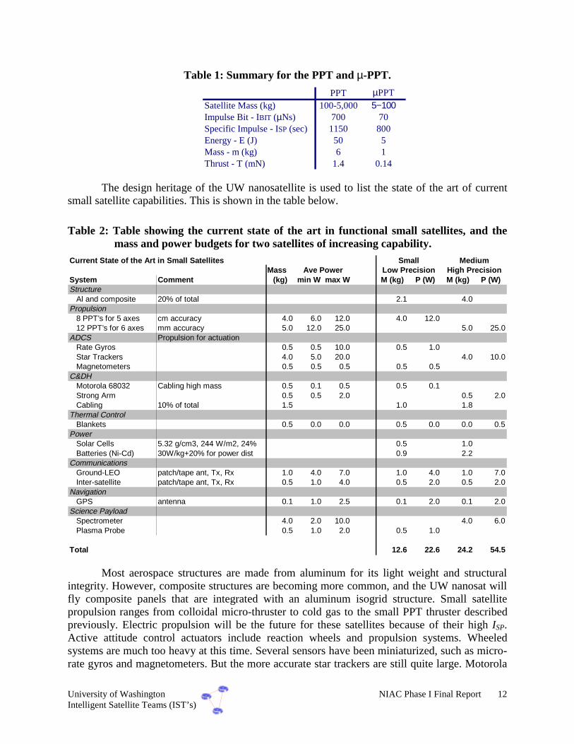
University of Washington NIAC Phase I Final Report 12Intelligent Satellite Teams (IST’s)
Table 1: Summary for the PPT and µ-PPT.
PPT µPPTSatellite Mass (kg) 100-5,000 5−100Impulse Bit - IBIT (µNs) 700 70Specific Impulse - ISP (sec) 1150 800Energy - E (J) 50 5Mass - m (kg) 6 1Thrust - T (mN) 1.4 0.14
The design heritage of the UW nanosatellite is used to list the state of the art of currentsmall satellite capabilities. This is shown in the table below.
Table 2: Table showing the current state of the art in functional small satellites, and themass and power budgets for two satellites of increasing capability.
Current State of the Art in Small SatellitesMass
System Comment (kg) min W max W M (kg) P (W) M (kg) P (W)Structure
Al and composite 20% of total 2.1 4.0Propulsion
8 PPT’s for 5 axes cm accuracy 4.0 6.0 12.0 4.0 12.012 PPT’s for 6 axes mm accuracy 5.0 12.0 25.0 5.0 25.0
ADCS Propulsion for actuationRate Gyros 0.5 0.5 10.0 0.5 1.0Star Trackers 4.0 5.0 20.0 4.0 10.0Magnetometers 0.5 0.5 0.5 0.5 0.5
C&DHMotorola 68032 Cabling high mass 0.5 0.1 0.5 0.5 0.1Strong Arm 0.5 0.5 2.0 0.5 2.0Cabling 10% of total 1.5 1.0 1.8
Thermal ControlBlankets 0.5 0.0 0.0 0.5 0.0 0.0 0.5
PowerSolar Cells 5.32 g/cm3, 244 W/m2, 24% 0.5 1.0Batteries (Ni-Cd) 30W/kg+20% for power dist 0.9 2.2
CommunicationsGround-LEO patch/tape ant, Tx, Rx 1.0 4.0 7.0 1.0 4.0 1.0 7.0Inter-satellite patch/tape ant, Tx, Rx 0.5 1.0 4.0 0.5 2.0 0.5 2.0
NavigationGPS antenna 0.1 1.0 2.5 0.1 2.0 0.1 2.0
Science PayloadSpectrometer 4.0 2.0 10.0 4.0 6.0Plasma Probe 0.5 1.0 2.0 0.5 1.0
Total 12.6 22.6 24.2 54.5
Small MediumAve Power High PrecisionLow Precision
Most aerospace structures are made from aluminum for its light weight and structuralintegrity. However, composite structures are becoming more common, and the UW nanosat willfly composite panels that are integrated with an aluminum isogrid structure. Small satellitepropulsion ranges from colloidal micro-thruster to cold gas to the small PPT thruster describedpreviously. Electric propulsion will be the future for these satellites because of their high ISP.Active attitude control actuators include reaction wheels and propulsion systems. Wheeledsystems are much too heavy at this time. Several sensors have been miniaturized, such as micro-rate gyros and magnetometers. But the more accurate star trackers are still quite large. Motorola

University of Washington NIAC Phase I Final Report 13Intelligent Satellite Teams (IST’s)
processors have been used for year aboard satellites, but with the development of embeddedsystems such as palm pilots, computational capability in terms of clock speed/W is drasticallyincreasing. The StrongArm processor, due out in months, will have a clock speed of 600 MHz ata power of 0.5 W. Solar cells are now currently being developed that are 24 and 26% efficient.While novel Li based batteries are starting to replace NiCd because of their storage capability, itwill be a few years before they are space qualified. Communications (and GPS) have drasticallyimproved with antenna developments such as the patch and tape antennas. And although thereare too many science instruments to list, the plasma impedance probe or a simple spectrometerare two instruments common to earth scientists.
3.2. MEMS Based Components
Satellite subsystems that are currently being examined in the MEMS community includeattitude determination sensors and control and actuators, propulsion, communications, power,flight computers, mission instrumentation, satellite scale thermal management, and the spacecraftchassis. Within this list, the most mature systems are those that offer the greatest benefit fromimplementation in MEMS or those with terrestrial market pressure. The current pressure withinthe personal communication industry is driving a number of technologies that can directly crossover into the space community. Two of the more dramatic devices, that will both soon be readyfor satellite integration and flight testing are MEMS gyroscopes and RF switching components.
Attitude Determination Sensors
Greater than an order of magnitude improvement in volume and power can be found inmoving from large scale gyroscopes to the MEMS equivalent. The typical drift performance forMEMS gyroscopes is between 0.1 degrees per second [26] and 0.16 degrees per second [23].This is worse than its macro scale equivalent which can routinely obtain drift rates from 0.003degrees per hour to 1 degree per hour [24]. Researchers are currently working to ensure that theMEMS version quickly catches up to this standard for the reason that drift is a large factor indetermining the usefulness of the device in a given application and is proportional to the pointingaccuracy of the satellite under gyroscopic control. Even if they lag in this parameter, MEMSdevices are inherently better in other regards. In comparing the power required by the two types,the MEMS version needs on the order of milliwatts due to its capacitive sensors while full scalegyroscopes require between 10 and 200 watts [24]. Weight is another parameter where MEMSexcel. MEMS gyroscopes are small and light, requiring only a small IC package which mayweigh only a few grams. On the other hand, a conventional gyroscope can weigh between 3 and25 kg and take up 100 cubic centimeters or more [24]. Although MEMS gyroscopes are notquite ready for space flight they are under substantial development pressure due to the clearadvantages concerning power, weight and volume consumption.
This advancement in the MEMS community towards finding solutions to spacecraftsubsystem problems does not end with strictly mechanical, movable structures. One possibleinroad for MEMS is the star tracker. The current state of the art combines a CCD camera,digitizer and computer to produce the final instrument. Even though this system has undergonenumerous stages of optimization and minimization, an assembled instrument is unavoidablebecause the semiconductor processes for these components are mutually exclusive. In addition,CCD technology is notorious for its power consumption. Using MEMS and a CMOS imager,

University of Washington NIAC Phase I Final Report 14Intelligent Satellite Teams (IST’s)
this entire package could be shrunk to a single semiconductor die. Currently CMOS imagers areavailable that allow for separate, electronic shuttering over the focal plane [18] and whosedesigned purpose is as star trackers. The independent shuttering feature enables local controlover sensor integration times so that a greater range of stellar magnitudes can be used whendetermining orientation. This device does not currently incorporate focal plane processing;however, data converters and processors have been integrated with these sensing elements in thepast. This would allow the star tracker to shrink to a single chip, possibly to a single IC packagewith a commensurate reduction of power and volume requirements.
Attitude Control Actuation
Beyond sensing systems, MEMS can provide means to control the satellite’s orientation.Momentum devices overcome some of the disadvantages of rocket-based approaches byfeaturing high pointing accuracy, precisely controllable slew rates, and potentially very long lifespan -if powered by solar energy. The UW is currently investigating MEMS devices that usemomentum to produce attitude adjustments, including momentum wheels and momentumactuators. Typically these devices generate low levels of torque; but their pointing accuracy ishigh. In the case of momentum wheels, torque is exerted on the spacecraft by changing the speedof multiple spinning disks. In MEMS implementations, the lack of absolute speed control andvery low friction bearing surfaces make this scheme difficult. The second technique, which lendsitself more to MEMS technology, is to mount a spinning disk on gimbals. As the platform isactuated, force is imparted due to the change in direction of the angular momentum vector. Eventhough MEMS devices can only generate relatively small momentum due to their small size andlow weight, arrays of devices and additional miniature flywheels are options to overcome theselimitations.
ω Ω
Figure 7: Wheel of a CMG.
Momentum wheels and control moment gyros are the two main techniques used tocontrol the attitude of a spacecraft (3 angular degrees of freedom) that do not rely on thrusters.Momentum wheels are based on the principle of conservation of moment of inertia. Change inthe angular velocity of a spinning disk results in an angular (de-)acceleration of the spacecraft,where its rate is proportional to the disk acceleration as well as the ratio between disk andspacecraft moment of inertia. Momentum wheels require a continuously spinning disk. Sincelow friction bearings are difficult to achieve with microfabrication, momentum wheels arecurrently impractical for small spacecraft.

University of Washington NIAC Phase I Final Report 15Intelligent Satellite Teams (IST’s)
In addition, it appears that MEMS is ill-suited for all systems that take advantage of(moment of) inertia, due to the unfavorable scaling effects at the microscale. Mass scales withthe third power of size, and moment of inertia scales with the fifth power. Moving from meter-scale devices down to millimeter scale may result in a downscaling of the effective forces ortorques by a factor of 1015! However, the following analysis argues that these scaling effects donot always apply, and that it is indeed practical to build a micro control moment gyro.
Control moment gyros (CMG’s) take advantage of the Coriolis force that acts on asystem when a spinning disk is forced to change its axis of rotation. The resulting torque can becalculated as
Ω= IT
where I = π/2 ρ hr4 is the moment of inertia of the spinning disk with radius r andheight h, ω is its angular velocity, and Ω describes the change in the axis of rotation. To avoidproblems with continuously spinning disks as mentioned above, the MEMS CMG usesoscillating deflections rather than continuous rotation. If the maximum deflection is given by Θ0
and f is the frequency of deflection, then the deflection can be described as
IW W 2sin0=
and
IWI(t) t 2cos2)( 0== &ω
Furthermore, if the disk is mounted on a gimbal that oscillates at the same frequency fand with a maximum deflection of Ψ0, then the following deflection is obtained:
IWt 2sin)( 0=
and
IWItt 2cos2)()( 0== &
The torque T can be calculated resulting from the Coriolis force as
02cos22cos22cos2 200
42300
4
2≥=⋅⋅=Ω= IWhrfIWIIWIhrIT ρπρω π
Note that T is a time-dependent but always non-negative. This shows that it is possible togenerate a non-zero torque without a continuously spinning disk. In addition, it is straightforwardto show that a phase difference of 180° between disk and gimbal oscillation results in a negativeresulting torque T.
The question remains about the effectiveness of a micro CMG, based on this analysis.Note that the torque generated by the CMG, as well as the required torque for attitude change,are proportional to the moment of inertia, and thus scale at the same rate. Hence, if the relative

University of Washington NIAC Phase I Final Report 16Intelligent Satellite Teams (IST’s)
size of the CMG and the spacecraft are held constant, then the effectiveness of the CMG is scale-independent.
Based on these promising theoretical results, a design study for a CMG has begun thatcould be fabricated with a standard MEMS foundry process. Several issues pose challengingconstraints on such a design:
1. Ensure a high oscillation frequency f to obtain reasonably-sized torques (recall that T ~ f2).
2. Ensure that the natural frequency of the oscillating disk matches the natural frequency of thegimbal mechanism.
In both cases, torsional springs are employed whose stiffness can be varied by thedimensions of the torsional beam (length, width, thickness). However, the fabrication processesset severe limitations on these dimensions. Preliminary calculations show that a torque of T = 310-13 Nm are feasible. This torque would accelerate a silicon sphere of radius 1mm by about4°/sec2, by far sufficient for attitude control.
Figure 8: Micro Control Moment Gyro.
In a CMG, two torques are generated: a desired torque in one direction and an undesiredtorque in an off-axis direction. In scaling down the CMG and placing many of them side by side,the resultant torques from the off axis can be canceled, and the spacecraft is left with simply asummation of the desired torques for attitude control.
Figure 8 shows a schematic view of the elements and orientations of the variouscomponents (not drawn exactly to scale). The platform is suspended above an underetchedsection and holds the rotor and its stators which are driven out of phase with each other. A metalflywheel can be deposited on top of the rotor to increase the angular momentum of the spinningdisk. The rotor itself, made from polysilicon, is attached to the plate using a polysilicon bearing.The plate on which the rotor and flywheel spin is attached to the substrate by two torsionsuspension arms. These arms allow the platform to gimbal in one dimension and allow for powerconnections to the movable section. The motion of the rotor can be produced either by magneticor electrostatic actuation.

University of Washington NIAC Phase I Final Report 17Intelligent Satellite Teams (IST’s)
Micro-Propulsion
The development of micropropulsion is seen as a key development for IST’s because oftheir possible remote location and distributed measurement requirements (such as various formsof interferometry). In addition, this area is currently receiving a lot of attention in the MEMScommunity [3]-[7]. Current thrusters fall into three main categories: monopropellant,bipropellant and electrical. As technology has improved, each of these types has carved for itselfits own niche, specifically suited to its characteristics.
Figure 9: Fabrication of micro-propulsion. The top figure shows the digital thrusterconcept from Lewis et al [3]. The bottom figure shows the micro-thruster chippackage.
All of these systems can be implemented at a MEMS scale with enough effort. Smallscale versions of solid rockets are easily integrated with numerous advantages compared tolarger scale systems. To their benefit, the MEMS solid propellant engines are compact, involveno microfluidics, and provide throttle control by allowing numerous tiny, single use thrusters tobe fired together or individually depending upon the necessary thrust. These systems currentlyare limited in their thrust duration - typically less than 1ms. Monopropellant systems are better insome regards, but more difficult to realize. A monopropellant system has the advantage of highimpulse without cryogenic fuels, dual fuel tanks and complex methods of ignition. Amonopropellant system does allow for resizable fuel tanks (based on mission specification),consistent nozzle placement and continuous thrust over solid propellant systems. Finally,

University of Washington NIAC Phase I Final Report 18Intelligent Satellite Teams (IST’s)
bipropellant systems, similar to their macroworld counterparts, offer the best performance at thehighest level of cost and complexity.
Communications
RF switches are another technology under terrestrial market pressure; however, these arevirtually ready for space flight. A conventional RF switch and filter combination requires 880cubic cm and weighs 1.5kg for an X-band system and 608 cubic cm and 1.2 kg for a Ku-bandsystem [24]. Just including this component will take up the entire weight budget for a smallsatellite and severely stress the volume requirement as well. This package could be replaced byan entirely microfabricated system which will exhibit better performance at workable weightsand volumes. RF switches have already been exhibited, taking up only a few thousand squaremicrons of chip area and handling powers in excess of 1W. If more power handling is needed,these devices are easily fabricated as arrays. A typical device works from DC to GHzfrequencies and has an insertion loss below 0.1 dB [9j]. For filtering, mechanical RF filters arebecoming available that rival conventional components in insertion loss and quality factor [3j].With the possibility of fabricating both of these devices on the same substrate the volume andweight are decreased even further. The possibility exists for shrinking the above, conventionaldevice to a few milligrams and much less than one cubic cm while improving performance.
Communication subsystem development, especially inter-satellite communication, is alsoreceiving a lot of attention as the bandwidth requirements increase. These new systems facilitatethe efficient pointing, tracking, and high-bandwidth modulation of optical and microwave beamsby the smart design of new materials and devices. Switching and processing of information isultimately limited by the mutual interactions between signals and the ability of the hardware tofilter and amplify these signals as they climb into optical and microwave frequencies. Asubstantial step towards this goal were polymer modulators, developed at the UW, which holdthe world record modulation rate of greater than 340 Gbps. The development of this type ofMEMS will be central to pointing and tracking of optical and microwave beams for intersatelliteoptical links and microwave up/down links; and will also radically improve the viability ofputting high-performance communications-grade lasers into space-based intersatellite opticallinks. New manufacturing processes for polymer fibers enable lower network connection costsfor devices on the spacecraft chassis and will facilitate the development of new high performancecommunications transmitters.
In the here and now; MEMS are ready to make serious inroads on specific RF designproblems independent of high frequencies and purely semiconductor nature of typical RFdevices. The first major inroad is the RF switch. Typical RF switching is done with PIN diodesand, although it is an adequate scheme, these introduce harmonics that may need to be filtered,insertion losses and another set of coaxial interconnections [25]. MEMS RF switches on theother hand are like relays for RF frequencies. When energized they physically close or open,making or breaking the link between the amplifier and the antenna. This switch technique resultsin dramatically less loss, no unwanted harmonics and since these devices are IC technologycompatible they can be fabricated in situ with RF amplifiers for a further savings in volume [24].Using this technology and various delay lines it is easy to imagine creating digitally controlleddelay lines for integrated phased array systems.

University of Washington NIAC Phase I Final Report 19Intelligent Satellite Teams (IST’s)
MEMS oscillators are closely behind RF switches in their development curve and willshortly become an important player in the RF field. Most current RF systems rely on crystaloscillators to produce an accurate frequency reference. These have a long development historyand show up in a myriad of applications; however, there is no method to place these oscillatorsdirectly onto the communications chip to yield a fully integrated solution [19]. Mechanicalresonators can solve this problem and allow the local or reference oscillator to be integratedalong side the rest of the RF transistors in the communication system [19]. This solution relieson the high and clean resonance frequencies of silicon beams to produce frequencies that arestable enough to use in communications devices.
Power
None of these devices will function without a source of power and here, MEMS has acontribution to make as well. For solar power there are issues in solid state physics that limit theconversion between light and electricity to around 30% [17]. In the terrestrial world, conversionefficiencies hover just under 20% and satellite designers typically consider 15% to be theeventual, on orbit conversion efficiency of their solar panels [24]. MEMS technology can helpbring that number closer to the theoretical maximum with a number of techniques. First, lensescan be etched directly into the surface of the silicon wafer. This focuses the light onto the diodesthat make up the light gathering component of the cell improving efficiency. Secondly, thenecessary metal interconnects can be angled such that the light otherwise lost in their shadow iscaptured [20]. Both these methods can be currently found in prototypical solar panels poised forentry into the commercial market [24] and could be quickly incorporated into miniature or fullscale satellites.
MEMS can go beyond improving solar conversion and take a role in actively regulatingor storing electricity. One example of this is the possible development of solar cells with smartshadow compensation. In a conventional solar array, if any single cell is shadowed then theentire string that cell is attached to will become and open circuit. This becomes an especiallythorny issue near satellite chassis and results in solar arrays being mounted on booms away fromthe satellite. By combining solar cell technology with the mechanical switches similar to the RFswitches smart solar cells can be constructed that automatically remove themselves from thechain if light ceases to fall on them. If these cells are used in spacecraft solar panels then theindividual cells can be wired in the most convenient manner and the panels themselves placed onshorter booms. Another example of smarter solar cells is to place sensing hardware right on thesolar panel. This would eliminate another set of connectors and provide for a greater density ofdevice packing on the satellite. Good candidates for this style of integration are sun and earthsensors.
To store electricity, the MEMS community is moving quickly to establish workable thinfilm batteries [27]. At the moment these batteries are limited to slow discharge rates and absolutepower storage but the future is open to massive parallel and series arrays of these batteries.These configurations stand to improve current battery technologies by allowing for a far greateranode and cathode surface area. Outside of the MEMS community, the Li Polymer batteries areboth higher in storage and environmentally acceptable. In addition, the polymer battery beingdeveloped could be used in a multi-functional nature, such as part of the structure.

University of Washington NIAC Phase I Final Report 20Intelligent Satellite Teams (IST’s)
3.3. Systems-Level Integration of MEMS Based Components
Integrating many of these subsystems together, a proposed MEMS based docking systemfor small spacecraft is given as follows. Consider, e.g., the free-flying camera satellite. At theend of a free-flight mission, the satellite navigates towards the docking site. The free flyer mustfirst locate the secondary platform and navigate towards the docking site. As the two spacecraftget closer, the requirements on their positioning become more stringent. Contact is then madewith some position uncertainty, based on limitations of the navigation vision system andprecision docking requirements. The coarse navigation step can be accomplished using GPS forsensing and a variety of thruster systems. Fine navigation (just before docking) is more difficultbecause cm level accuracy is required. Sensing can be accomplished using several approaches:GPS using the differential carrier phase, or a laser/vision system and three “targets” on thesecondary spacecraft. The actuation must be accomplished by a thruster system with a very smallimpulse capability, such as pulsed plasma thrusters.
Figure 10: Conceptual MEMS based docking system.
A design by the UW takes advantage of recent advances in microelectromechanicalsystems (MEMS) which allow batch fabrication of thousands of devices in a single fabricationrun on a silicon wafer. The proposed system is based on microactuator arrays [8]-[10] that havebeen developed in our group over the past six years. These devices have already been used insuccessful demonstrations of precision positioning under optical and scanning electronmicroscopes (air or vacuum as ambient medium). The lift capacity of a single actuator has beendetermined as approximately 76µN [8]. A motion pixel consists of 4 actuators and covers(1.1mm)2. Thus, for a disk with a 4in diameter, a maximum normal force FN = 4 × 76µN /

University of Washington NIAC Phase I Final Report 21Intelligent Satellite Teams (IST’s)
(1.1mm)2 × π (2in)2 × (25.4mm/in)2 ≈ 2N is obtained to keep the satellite in contact with thedocking site.1 Hence, if a docking plate with a 4in diameter is chosen, the normal force must beheld under 2N. To maintain this force, the most efficient approach is to use a magnet2 (andpossibly a force/displacement sensor in closed loop). The shear forces can be approximated by FS
= ¼ µr FN (µr is the friction coefficient) since force in a specific direction can be generatedusually only with ¼ of all available actuators. Note that these calculations are conservative. Farless thrust is required to maintain contact without slipping, thus low power pulsed plasmathrusters are an alternative. In experiments very low normal forces (several µN) were sufficientto induce motion in silicon chips. Ultimately, the speed of operation will depend upon the normalforce as well as the inertia of the smaller satellite (or, more precisely, the reduced mass of thepair).
The MEMS actuators have been used in micromanipulation experiments wherepositioning accuracy in the single micrometer range was demonstrated. Strategies for open-looppositioning with submillimeter accuracy is possible as well [11]. The current actuator designachieves speeds of up to several cm/min. A prototype with 256 actuators requires approximately50mW of average electrical power when operated in vacuum. For an array with a 4in diameter,an energy-optimized design operating at less than 1W is envisioned. The MEMS positioningsystem is less than 1mm thick, resulting in a mass of less than 10g (far less than the clamps ormagnets). Furthermore, since the force generated by individual actuators is in the micro-Newtonrange, damage to the surface of the plate is not expected, even if the surface consists of, e.g., asolar panel. Hence the plate can be used for different purposes during free-flight.
Another interesting MEMS concept is the integration of more than one MEMScomponent into a micro-device. For instance, one could conceive of layering several of thefollowing thin components: thin film layers for power (solar cells or thin film batteries),microelectronics (navigation, signal processing), propulsion and actuation (micro combustion,CMG), communication (laser - short range, µwave phased arrays - long range), and sensors(cameras, spectrograph). Each of these devices is currently under development, although not forintegration into one package.
Solar cells/thin film batteries
Microelectronics
Micro-gyros
Micro-CMG’s
Figure 11: Integrated micro-system of a future micro-satellite.
1 If force is exceeded, actuators are completely flat and no actuation is possible. However, they are not damaged by higher normalforces.
2 Magnet is analogous to magnetic bases on optical tables, which achieve pull to weight ratios of 50:1 (e.g. Edmund ScientificH39926)

University of Washington NIAC Phase I Final Report 22Intelligent Satellite Teams (IST’s)
3.4. Performance and Cost Benefits for MEMS
The performance and cost benefits of using MEMS based subsystems are derived in threeareas: the small size and weight, the power consumption, and the low manufacturing cost due tobatch fabrication. These benefits may be of several orders of magnitude, and may involve one orseveral of these parameters. It is noted, however, that these benefits may come with trade-offs insystem performance and life expectancy. MEMS reliability is an area of very active research.To this date, data on long term performance and fatigue in MEMS devices is sparse. Exposure toharsh space environments and radiation without shielding may increase the effects of materialdeterioration and defects. In general, the largely reduced cost in manufacture and delivery ofMEMS space systems will more than offset a somewhat shorter lifespan of these systems. Thefollowing is a summary of the near term estimated performance and cost benefits of usingparticular MEMS components.
For the communications field MEMS currently offers solutions to filtering, switchinglocal oscillation [19], [25]. Radios are currently adapting an increasingly integrated processes assemiconductor materials are able to handle higher frequencies. By using MEMS whereverpossible not only is there a weight and volume benefit from the device itself but from the lack ofassociated connectors, cabling, casework and packaging.
Table 3: Summary of MEMS communication components advantages.
FrequencyRange
Macro sizedmass [24]
Macro sizedvolume [24]
MEMS mass MEMSvolume
X-Band 1.5 kg 880 cm3 100 g 0.5 cm3
S-Band 2.0 kg 2700 cm3 100 g 0.5 cm3
Ku-Band 1.2 kg 608 cm3 100 g 0.5 cm3
The MEMS weight and volume remains constant because for MEMS RF switches thesize is frequency independent and for mechanical filtering the carrier package dominates theweight and volume figure over the die mass [17]. For the table above the numbers reflect a fullduplex communications link.
Antennas sizing is largely driven by carrier frequency bandwidth and as a consequenceMEMS, fabricated antennas are seen as unlikely. There is the possibility for MEMS to be usedas digitally controlled, phased array delay lines; however, this is still one step back from theantenna proper.
In expanding the definition of MEMS to include highly integrated, mixed signal devicesan avenue for MEMS based imaging systems is opened. These have the advantage of being ableto vary exposure time across the focal plane while consuming far less power than similar CCDsystems [18].

University of Washington NIAC Phase I Final Report 23Intelligent Satellite Teams (IST’s)
Table 4: Summary of MEMS attitude determination sensor advantages.
Pointing Family Macro sizedmass
Macro sizedpower
MEMS mass MEMS power
Star tracker 3 – 7 kg 5 – 20 W 1 – 5 kg 100mW – 1WHorizon sensor 2 – 3.5 kg 0.3 – 10 W 0.5 – 2 kg 200mw – 1WSun sensor 0.2 – 2 kg 0 – 3 W 0.2 – 1.5 kg 0 – 1Wmagnetometer 0.6 – 1.2 kg <1W 150 mg – 0.5 kg < 500mW
For the first three entries there is no dramatic weight loss because all of these systemsrequire external optics for operation. In this instances, MEMS is more valuable for its reducedpower consumption than the reduced mass. One of the most useful modifications is moving thehorizon sensor away from its current spinning mirror to a MEMS positioning system.
The ability to generate power from solar radiation has benefited remarkably from theapplication of MEMS techniques. Using surface micromachining it is possible to integrate smallsurface lenses directly into the solar cell and to angle the metallic interconnections to reduceshadowing. For the table below the figures are given assuming 1353 W/m2 of solar radiation anda photocell that is 0.5mm thick [17].
Table 5: Summary of MEMS attitude determination sensor advantages.
Si (2.328 g/cm3) GaAs (5.32 g/cm3)Macro area efficiency [24] 190 W/m2 244 W/m2
MEMS area efficiency [20] 392 W/m2
Macro mass efficiency 163 W/kg 77.2 W/kgMEMS mass efficiency 336 W/kg
In the future it is easy to imagine further improvements, such as micromachined heatsinkscovering the back of the cell for thermal dissipation or microactuators individually steering eachsolar cell for maximum power generation capacity.
The macro world provides no realistic solutions to propulsion in a micro-satellite. Thesmallest commercial thrusters, weighting tens of kilograms and producing Newtons of thrusts,typically dwarf even the largest micro-satellites [24]. For even a ten kilogram satellite thethruster alone uses up the entire weight, power and volume budget. To address these concernssmaller thrusters are now under development. These include conventional devices built to asmaller scale and true MEMS. Primex Aerospace Company and the UW has begun thedevelopment of small scale PPT that deliver 0.14 mN of thrust while only taking 100 cm3 andusing 12 watts of power. While this device is conventionally machined and produced, it hasdirect applicability to the microsatellite community due to its small size and simplicity. Astrictly MEMS based solution to this problem is embodied by the TRW digital thruster. Thisapproach involves the fabrication of thousands or millions of single use, chemical thrusters on a

University of Washington NIAC Phase I Final Report 24Intelligent Satellite Teams (IST’s)
silicon wafer. Prototypes, so far, have consisted of a layer of micromachined pits into which thepropellant is placed and a combination burst plate and nozzle which is fitted over that. Circuitryto handle ignition is typically placed on the first layer [22]. The systems demonstrated so fartypically leave 80 percent of their propellant unburnt; however, effort is underway to improvethat figure and to test this device in space as soon as possible [22].
3.5. Prototype MEMS Based Satellite for IST Missions
In order to assess the full impact of MEMS on satellites within the IST, the results of theMEMS research is compiled into a table analogous to that of the current state of the art in smallsatellites, shown on Page 12. It is noted that this table is derived from current researchprojections from UW, NASA, industry, and other government organizations. It is meant to showthe trend in future satellites, not necessarily the ease in development of course. Note, however,that the tables were designed to have approximately the same performance capability in terms ofmovement and science.
Table 6: Table showing the projected MEMS components and microspacecraft that arefully functional. Included are the mass and power budgets for two satellites ofincreasing capability.
Projected Microtechnology Based Small SatellitesMass
System Comment (kg) min W max W M (kg) P (W) M (kg) P (W)Structure
Composite, Self-consum10% of total 2.5 0.0 0.0 0.5 0.8Propulsion
MEMS Digital Prop cm accuracy 0.5 20.0 20.0 0.5 20.0MEMS Digital Prop mm accuracy 1.0 40.0 40.0 1.0 40.0
ADCS Propulsion for actuationRate Gyros 0.1 0.1 0.1 0.1 0.1Star Trackers 1.0 1.0 1.0 1.0 1.0Magnetometers 0.2 0.2 0.2 0.2 0.2
C&DHFrom Embedded Systems 0.2 0.1 0.1 0.5 0.1Cabling 2% of total 0.0 0.1
Thermal ControlBlankets 0.5 0.0 0.0 0.5 0.0 0.0 0.5
PowerSolar Cells 3 g/cm3, 494 W/m2, 35% 0.2 0.4Batteries (Li-Poly) 300W/kg+20% for power dist 0.1 0.1
CommunicationsGround-LEO patch/tape ant, Tx, Rx 0.1 4.0 7.0 0.1 4.0 0.1 7.0Inter-satellite patch/tape ant, Tx, Rx 0.1 1.0 4.0 0.1 1.0 0.1 4.0
NavigationGPS antenna 0.1 1.0 1.0 0.1 1.0 0.1 1.0
Science PayloadSpectrometer 1.0 1.0 1.0 1.0 1.0Plasma Probe 0.1 0.5 0.5 0.1 0.5
Total 2.9 26.9 4.6 54.5
Ave Power Low Precision High PrecisionSmall Medium
The mass reduction is the result of the use of composite structures and multifunctionalstructures, such as using Li Polymer batteries. MEMS based propulsion, along the lines of thework at TRW should provide excellent propulsive capability for the small satellites. Intelligence

University of Washington NIAC Phase I Final Report 25Intelligent Satellite Teams (IST’s)
facilitates reconfigurability of a satellite system which allows the system to achieve a higherlevel of upgradability and fault tolerance. The attitude determination sensor is a MEMS basedstar tracker for the higher precision satellite, and MEMS based gyros and magnetometers for thelow precision satellite. The processor has benefited from heavy developments in embeddedsystems to yield a very low power system. The percentage of cabling mass has drasticallydiminished because of the advanced packaging of MEMS components into integrated micro-systems. Solar cell efficiency (and individual cell pointing) have improved the power generation,although only by a factor of two. Batteries are now taking advantage of the multi-functionalityand energy storage of Li polymer batteries. Communications components now in weight andvolume from the device itself, as well as the lack of associated connectors, cabling, casework andpackaging. The spectrometer has also decreased in size and power using MEMS technology.
This aggressive use of MEMS spacecraft subsystems results in mass reduction of at leasta factor of four in the low and high precision satellites. Power consumption by both satellites isabout the same because the power budget of both systems is dominated by identical propulsionsystems. If the MEMS based satellite in this example had used a system similar to TRWs digitalthruster then an order of magnitude reduction in power could have been realized. By reducingthe mass of the satellite there is an obvious reduction in the cost to place the satellite into orbitand once their maneuver it.
3.6. Micro-Subsystem Conclusions
With all these technologies there is no quick and easy solution. Thus, the challengesfacing the MEMS community are great when it comes to the development of an integratedMEMS spacecraft. There are a number of efforts underway for specific MEMS components,such as micro-propulsion and micro-sensing and instruments. However, once these problems aresolved, the real challenge begins in integrating these subsystems into one, inexpensive,manufacturable package. Once this is commonplace, the final challenge is laid out: thedevelopment of a complete MEMS spacecraft. To get to this point engineers and scientists mustlook beyond technical hurdles to a field of psychological and conceptual issues. The foremost ofthese is letting the mission be driven by the technology as opposed to the converse. Withemerging technology such as this there is a tendency to force MEMS to fit into a technologicalniche or to overlook a better performing, large scale analog in the pursuit of the perceived stateof the art. In the upcoming years and after a few successes, MEMS will be touted as the musthave technology for any space mission. It is important that even with all the fanfare, of whichquite a bit is deserved, MEMS is treated as any other technological tool as opposed to a panacea.In the long run the use of MEMS in spacecraft subsystems will benefit more from a calm,analytical perspective than irrepressible enthusiasm.
Other specific conclusions for MEMS components in space include:
• Several subsystems are well on their way to maturity because of government and industryfunding. These include MEMS based propulsion, micro attitude determination sensors suchas gyros and star trackers, and low power processor boards based on embedded systems.

University of Washington NIAC Phase I Final Report 26Intelligent Satellite Teams (IST’s)
• The key to developing a MEMS based satellite is integrating the smaller components intomodular, low power, lightweight, and possibly multi-functional packages that can bemanufactured inexpensively, and can be used in several types of satellites.
• The biggest roadblock to a MEMS based satellite in deep space is power. The solutions forthis include low-power devices and circuitry in combination with improved solar cells andthin/thick film batteries, In addition, novel energy are sought, such as beamed energy sourcefrom a local mother satellite, or one-shot energy supplies that allow a short burst of energyfor long range communications once the mission of the picosat has been finished.
• Within 10 years, a satellite of equal capability can be developed using MEMS components ata mass savings of a factor of 4.

University of Washington NIAC Phase I Final Report 27Intelligent Satellite Teams (IST’s)
Chapter 4: Autonomy
While miniaturized devices are now being researched and developed, the potential forlarge number of satellites within the fleet creates a dire need for distributed control and higherlevels of autonomy. With tens, hundreds or thousands of satellites envisioned, they mustautonomously work together for mission success in order for the IST vision to become a reality.Many questions require answers, such as: How much intelligence is required on each satellite?,Are all satellites identical?, and How can a mission objective be encoded and accomplished by afleet of autonomous, intelligent satellites?
4.1. Overview of Autonomy Concept for IST’s
A complex autonomous system of interacting satellites would have a control structurecomposed of three levels. Since the system will interact with human ground control, the firstlevel will be interactive mission control. The second will be the outer loop navigation of the IST.The third level will be the inner loop control for individual satellites of the IST. These threelevels are shown in Figure 12. This hierarchy fits naturally into the framework of intelligentcontrol systems which are based on fuzzy logic, artificial neural networks, evolutionaryprogramming (or combinations thereof) [12]. While the current state of technology holds greatpromise for multi-level control of complex systems, there are still many issues that need to beaddressed in the context of the specific systems to which the technology will be applied. Thecapabilities of an ideal multiple satellite system include:
– Coordinate in close formation, at a variety of precision levels (distributed control).– Receive a mission goal and distribute tasks to individual satellites (planning).– Decide which platforms, how many, and when individual satellites should act (scheduling).– Evaluate an individual satellite failure and recover from it (fault detection and recovery).– Adapt the information flow (communications) depending on changing system parameters.– Upgrade a new satellite that is possibly different (upgrade).– Train for a mission, or learn from any mistakes that occur during the mission (learning).
These are succinctly shown in Figure 13.
Figure 12 also shows that traditional AI technologies have now been expanded in termsof the fleet. Planning and scheduling includes scheduling for different platforms (fleet), as wellas their subsystems (individual). Communication can occur between the ground station and fleet,

University of Washington NIAC Phase I Final Report 28Intelligent Satellite Teams (IST’s)
FLEET
INDIVIDUALPLATFORM
INTERFACE
OPERATOR
inner-platform communication
subsystem planning & scheduling
individual adapting, learning, ...
mission goals...OPERATORCOMMAND
CENTER fleet planning & scheduling
ground-fleet comm
FLEET COORDINATION
INDIVIDUALPLATFORMCONTROL
inter-platform comm
individual s/c planning & scheduling
fleet adapting, learning ...
collaborative behavior
Figure 12: Flow chart showing the general hardware on the left, and the layeredarchitecture on the right. Overlapping aspects can exist on either layer.
Prior Training(learning)
Operator Interface
SchedulingPlanning
AdaptingLearning
P1
P2
P3
P4
P5
MissionGoals
Distributed Control
uncertainty
communication
fault detectionand recovery
Pn
upgrade
Figure 13: Summary of the capabilities for a fully autonomous, multi-agent system forIST’s composed of multiple satellites.

University of Washington NIAC Phase I Final Report 29Intelligent Satellite Teams (IST’s)
and between the individual spacecraft. Robustness now applies to failures of a platform withinthe fleet, as well as within each platform. Mission objectives are now embedded into the fleet,not an individual platform. A process of sharing information occurs, thus improving the fleet’schances of mission success. The fleet can reorganize itself, and allow different entities to enterand exit as needed.
Consider one of the most important tasks of an intelligent system, especially for multiplesatellites: scheduling. This is a key issue because it can be used at a variety of levels. First, it canbe used to break down mission goals into specific platform tasks. Second, it can be used in ahierarchical approach, such that mission goals from the operator are taken to fleet tasks, whichare taken to platform tasks, which are taken to subsystem tasks, and finally implemented using aseparate scheduler/planner agent at each level. This process is shown in Figure 14.
OPERATOR LEVEL
FLEET LEVEL
INDIVIDUALPLATFORM
LEVEL
communication
scheduling commun-ication
…
scheduling …platform 1
fleet
…
propulsion power …
collab-oration
missiongoals
…
scheduling …platform 2
subsystems 1
intelligent agent
Figure 14: The hierarchical approach to scheduling in a fleet of coordinated platforms,using layers of intelligent agents at the operator, fleet, and individual platformlevels.
Because of the wide variety of uses for scheduling and planning, several approaches canbe used. Most scheduling and planning tasks allow for many options. Exact solutions are notcommon, but rather heuristics are used to get as good as solution as possible. For example,suppose a task is sent to a satellite with a scheduling intelligent agent. This agent’s duty is tolocally schedule a set of tasks to complete its goal. If the set of tasks is large and unpredictable,a common approach for the agent is to randomly pick many sets of tasks and see which setssatisfy the goal. Then, the set which is most efficient (in terms of number of tasks, time, cost,etc.) is chosen. Or better still, once there are several sets of tasks that satisfy the goal, each ofthese sets can be altered slightly by changing a few or deleting tasks. After each change, theagent evaluates if the set of tasks still achieves the goal, and if the new set is more efficient thanthe old set. Thus, our solutions are locally optimized. Much work is done on improving localoptimizations so the schedule approaches the global optimum. Obviously, there is a trade-off

University of Washington NIAC Phase I Final Report 30Intelligent Satellite Teams (IST’s)
between cost and optimality of our solution. Greater insights into a specific problem domainallow more efficient heuristics.
The above example shows that organizing and coordinating the IST is a very importantand complex task. There are many options, and it is not clear which may be the best. Once theorganization is set, then there are a variety of tools that can be used to facilitate the other areassuch as communication and fault tolerance.
4.2. State of the Art in Intelligent Agents and Autonomy
Although artificial intelligence (AI) research extends over many fields, relatively little AIhas been applied to the domain of space satellites. For instance, planning and scheduling [28],[32], [47] as well as reasoning [35], [43], [44] are well developed areas of AI, but only recentlyhave they been incorporated onboard (e.g. Deep Space 1 and other New Millenium projects).Another area of AI research, multi-agent systems (MAS), has not been developed as well asplanning or reasoning, but its application to space systems offers tremendous possibilities interms of improved performance and reduced cost of missions. It will be now considered thecurrent state-of-the-art of multi-agent systems in AI and of intelligent agents in space, since theapplication of the former to the latter is not only helpful in achieving high-performance, low-costfuture missions, it is in fact necessary.
Intelligent Agents in Space
Multi-AgentSystems
Reasoning
Planning
Agents in Space
Field
MaturityAdvancedSimulation
[38], [51]
[36], [39], [52]
Paper Simulation Implementation
[49]
[50]
Figure 15: Maturity of using intelligent agents in space applications.
As one gains experience in space satellite systems, more of the decisions which need tobe made during the course of a mission can be automated. Some decisions, for which a totallyreliable, expert choice is imperative, must always be made via ground support. However, formost choices, a locally intelligent decision can be made onboard a satellite. Such on-boardartificial intelligence eliminates satellite-to-earth communication (and the corresponding ground

University of Washington NIAC Phase I Final Report 31Intelligent Satellite Teams (IST’s)
support) which is an expensive aspect of space exploration. Specifically, for a mission such asPluto Express, it is unreasonable to suppose many real-time mission decisions can be made onEarth when communication costs are so expensive in terms of power and time. Intelligent spaceagents not only offer an enabling technology, but they allow reduced costs, faster realization ofmission goals which leads to increased exploration results, and overall improved performance.
Planning and scheduling in an intelligent agent (such as a satellite) allow users to sendhigh-level goals to the agent rather than a set of exhaustive, detailed actions. The agent, then,can take the high-level goals and determine sub-plans which it can follow to achieve the goals.The agent will carry out the sub-plans by computing a schedule of its resources and subsystemswhich realize the sub-plans. This intelligence will be applied to space agents for the first timewith the New Millenium projects.
Reasoning in an agent allows the agent to reach an intelligent conclusion or decisionabout a given set of data. A set of data might consist of results obtained from sciencemeasurements or information regarding the status of a sub-system. A set of data generallycannot be defined explicitly because the data set is too large or because data is unpredictable(certain science measurements may be unanticipated or a strange system failure may yieldunexpected feedback). Thus, an agent must reach an intelligent conclusion about itsunanticipated data. Deep-Space 1 [13] began to take advantage of the autonomy allowed byreasoning with an agent. By comparing data from star trackers with pre-stored images, DeepSpace 1 has been able to effectively calculate its location on several occasions. Further use ofreasoning aboard agents will offer better adaptability to unknown situations and more autonomyof the agent. But it should be noted that the transition of the idealized technologies to actualspace implementation, as was found in DS-1 [14].
To date, multi-agent systems have not been incorporated into satellite missions, althoughfuture New Millenium projects will begin to utilize these ideas, such as formation flying forinterferometry missions (LISA [51]). Ideally, multi-agent systems will be employed in ahierarchical fashion. For instance, one can think of a particular sub-system, like propulsion, asan individual agent. The current satellite location and the desired satellite location may be sentto the propulsion agent (as a high level goal), with which the propulsion agent will plan andschedule its resources (thrusters) to achieve the goal. Thus, the propulsion subsystem will haveintelligence and can be thought of as an individual agent, so the organization of all the sub-systems, each an individual agent, will form a multi-agent system which comprises an entiresingle satellite. Of course, the single satellite will be an agent part of a satellite constellation(IST) which makes up a multi-agent system.
In a multi-agent system, each agent contains intelligence on its own, as well as all theagents exhibiting intelligence as a group. A few multi-agent systems have been implemented forreal-world applications [29], [30], [42], but it is difficult to implement effectively a multi-agentsystem [48].

University of Washington NIAC Phase I Final Report 32Intelligent Satellite Teams (IST’s)
Multi-Agent Systems
Negotiation
Contracting for Coordination
Autonomous Organization
Rational Communication
Generic MAS
Field
Maturity
Paper Simulation
AdvancedSimulation Implementation
[34]
[31], [40]
[29], [30], [41]
[45]
[34], [46]
Figure 16: Maturity of multi-agent systems with applicability to IST’s
Since communication is a premium in the space domain, it is important with aconstellation of satellites to ensure intelligent communication among the satellite agents so thatcommunication is not too costly. For the purposes of reducing communication, not only is itadvantageous to filter data sent from a MAS to Earth, but it is also critical to determine whichsatellites in the group need information from which other satellites and what information needsto be sent. Noh and Gmytrasiewicz [40] consider these issues in the domain of air defense byprioritizing communications within the MAS and intelligently classifying and selecting agentinteractions.
Autonomous organization of a MAS refers to the groups ability to autonomouslydetermine where in the group (since each agent has some intelligence) intelligent actions willtake place. For instance, only one satellite might communicate with Earth, and this satellite cando all planning and scheduling for the other satellite agents, or depending on the mission, theplanning and scheduling might be distributed among the MAS. Turner et al. [45] demonstratethe autonomous formation of intelligent underwater vehicles. The underwater domain (deep sea)closely parallels the space domain in that agents are essentially inaccessible by humans andcommunication is expensive/limited. In the underwater example, autonomous organizationsallows for additional agents and lost agents so that the MAS will reconfigure, and thus, itprovides a highly adaptive system.
Once a MAS is organized, further intelligent agent interaction can benefit the system.When an agent determines a plan to achieve a goal, the agent might recognize the benefits ofutilizing other agents in carrying out its plan. Thus, the agent might contract other agents to aidin its plan. This “contracting for coordination” is useful in realizing goals when not all agentsare being utilized, but in the space domain, where agent resources are precious, it may makemore sense to define goals explicitly for each agent. Another approach, for improving MASperformance once a plan for all the agents has been determined, is to allow each agent to attempt

University of Washington NIAC Phase I Final Report 33Intelligent Satellite Teams (IST’s)
to optimize the plan so less resources will be used. Here agents try to “negotiate” a better plan.This idea has been considered for air-traffic control [46] where each aircraft proposesimprovements to the current flight take-off/landing plan at an airport. The negotiation can yieldsubstantial plan optimizations, but tends to work best when each agent is competing with otheragents (e.g. for take-off/landing time) and trying to optimize the overall plan for its own benefit.In the space domain, satellite agents generally do not compete with each other; however, if asatellite schedules tasks for its sub-systems based on power constraints, each sub-system agentmay negotiate for a better plan where the sub-system is afforded more satellite power. Althoughmulti-agent systems are still in their infancy in terms of AI research, there is great potential intheir application to space satellite systems.
Figure 21 shows a summary of the coordination options for IST’s, as a function ofindividual agent intelligence and time. Currently, the best approach is a “Top-Down” approach,where there is one high level agent that has does most of the scheduling and planning, etc., withlittle interaction with lower level agents except for information exchange. This is similar to theDeep Space 1 model [13]. With new developments in on-board planning and reasoning, a neworganization can be developed termed “Multi-Agent Planning,” where a centralized hierarchy isstill used, but now the underlying agents can interact with the high level agent for the bettermentof the IST. After this technology advancement, the next step is to allow the agents to coordinatetogether, in a distributed Multi-Agent Planning architecture. This is the ideal case for IST’s, asthey take full advantage of their capabilities in terms of adaptability, distribution, andintelligence. Finally, if each of the individual agents is very intelligent, and has models of thecapabilities of each of the other agents, an architecture that allows individual planning can bedeveloped. This architecture is the most complex, and requires the most intelligence andcommunication between agents. And, it is not clear that there is a large benefit in jumping fromthe previous level. This architecture could work very well with more intelligent missions such asthe autonomous construction of a space facility.
4.3. Performance and Cost Benefits for Autonomy
When presenting autonomy ideas to both scientists and traditional space engineers, thequestion always arises, “Why should we change?” Put another way, “What can autonomy do forme?” This is a question so very important to the IST concept that it was addressed during PhaseI. Table 7 shows a summary of tasks for which autonomy based technologies can be used, versusthe “faster, better, cheaper” mantra of NASA. As with any advancement, there are trade-offs. Forinstance, one can reason about what science or telemetry data to send back. This has the benefitsof sending back better data if there is a limit of communications, but it also has the potential ofmaking more mistakes than a human would. This is especially true of critical, complex sciencedecision. In addition, the power required to send the information has decreased. As anotherexample, the IST must reconfigure if there is a loss of a satellite – a probable scenario with theIST concept because of the large numbers of satellites. By using autonomous operations, thiscould be done quickly such that the effects of the loss are minimized. If telemetry data must besent back to earth to evaluate the problem and wait for commands, valuable science time andperformance has been lost. In addition, the cost of operators has just increased.

University of Washington NIAC Phase I Final Report 34Intelligent Satellite Teams (IST’s)
Table 7: Autonomy based tasks and their potential performance/cost benefit.
FASTERTIME SCIENCE RELIAB DOLLARS POWER
Reasoningabout what science/telemetry data to sent back + - +about science/telemetry data to decide next task(s) + - + +about science/telemetry data to decide next task(s) - enabling +
Scheduling and Planningplan tasks for science + - + +schedule tasks for computations + + -
Adaptationreconfigure upon a loss of instrument or agent + - + +reconfigure upon a loss of instrument or agent - enablingreconfigure upon a gain of instrument or agent +adapting to small, unforseen events that limit performance + - + +
Learninglearning from events to prevent their recurrence + - + +
BETTER CHEAPER
Table 7 shows the most prevalent examples for IST’s. One should note that the mostprevalent disadvantage is reliability. And reliability in this case refers to the reliability in gettingthe best science data – per the NASA mission. It should be noted, however, that reliability insimple decision making for satellites has been shown to be better if the decisions are automated[57]. Basic telemetry data fits this category. Therefore, this study primarily examines sciencedata in important, complex decisions. The benefits include more time to collect science data,decreased operations costs, and lower power. These general trade-offs are now explored.
106
105
104
103
102
101
Data rate[bps]
Earth-PlanetDistance [AU]
1 3 10 30 100
Mars(Viking)
Jupiter(Voyager)
Neptune(Voyager)
Saturn(Voyager)
PlutoExpress
Telemetry dataIST-size 2000
Telemetry dataIST-size 200
Telemetry dataIST-size 1
Figure 17: Downlink data rate as a function of Earth-planet distance.
It takes both time and power to send data back to earth from space. Figure 17 shows aplot of the downlink data rates for several missions [56]. Note the correlation, which is primarilydriven by the large communications distance and the falling off of solar energy forcommunication power. This shows that the communication rates are fairly predictable for spacemissions, at least until optical communications become more common. Note also that severalcases of IST’s and their telemetry data are plotted, based on a minimum case of 500 bps for each

University of Washington NIAC Phase I Final Report 35Intelligent Satellite Teams (IST’s)
satellite. As the numbers of satellites increase in the IST, deep space missions become muchmore difficult without some level of autonomy described in Table 7.
Figure 18 shows a plot of the time it takes for a general iteration with a satellite on a taskthat requires the communication of 1 MB of data back to earth (and this data can be for any ofthe time critical tasks shown in Table 7). An example of this is the data required to reconfigurean IST after a failure. If this procedure were automated, notice the time savings that wouldoccur, which obviously increases dramatically in deep space. This is more succinctly describedin Figure 19 as the percentage of time communicating over total mission time, as a function ofthe number of events that require input from earth. This is based on a 100 satellite IST and a 6month mission. Assuming one event per day (180 total), one can see that the three outer planetswould waste all six months of time, while the inner planets waste several percent. By automatingat least the simple procedures within a mission, much more time could be devoted tocommunicating back science data and/or moving on to the next science task.
Ve MaMe Ju Sa Ur Ne Pl10
-2
10-1
100
101
102
Tim
e (h
ours
)
Distance (planet)
Figure 18: Plot of the communication time for 1 MB of data back to earth.
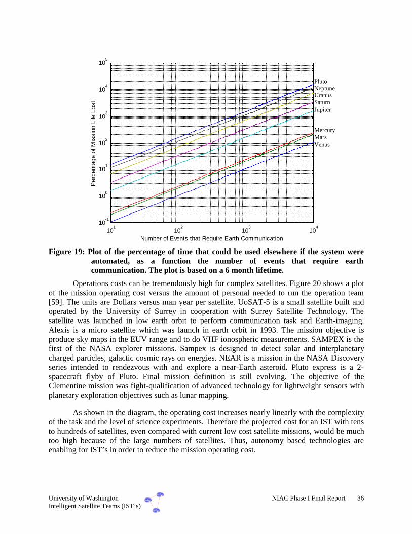
University of Washington NIAC Phase I Final Report 36Intelligent Satellite Teams (IST’s)
101
102
103
104
10-1
100
101
102
103
104
105
Per
cent
age
of M
issi
on L
ife L
ost
Number of Events that Require Earth Communication
Figure 19: Plot of the percentage of time that could be used elsewhere if the system wereautomated, as a function the number of events that require earthcommunication. The plot is based on a 6 month lifetime.
Operations costs can be tremendously high for complex satellites. Figure 20 shows a plotof the mission operating cost versus the amount of personal needed to run the operation team[59]. The units are Dollars versus man year per satellite. UoSAT-5 is a small satellite built andoperated by the University of Surrey in cooperation with Surrey Satellite Technology. Thesatellite was launched in low earth orbit to perform communication task and Earth-imaging.Alexis is a micro satellite which was launch in earth orbit in 1993. The mission objective isproduce sky maps in the EUV range and to do VHF ionospheric measurements. SAMPEX is thefirst of the NASA explorer missions. Sampex is designed to detect solar and interplanetarycharged particles, galactic cosmic rays on energies. NEAR is a mission in the NASA Discoveryseries intended to rendezvous with and explore a near-Earth asteroid. Pluto express is a 2-spacecraft flyby of Pluto. Final mission definition is still evolving. The objective of theClementine mission was fight-qualification of advanced technology for lightweight sensors withplanetary exploration objectives such as lunar mapping.
As shown in the diagram, the operating cost increases nearly linearly with the complexityof the task and the level of science experiments. Therefore the projected cost for an IST with tensto hundreds of satellites, even compared with current low cost satellite missions, would be muchtoo high because of the large numbers of satellites. Thus, autonomy based technologies areenabling for IST’s in order to reduce the mission operating cost.
PlutoNeptuneUranusSaturnJupiter
MercuryMarsVenus

University of Washington NIAC Phase I Final Report 37Intelligent Satellite Teams (IST’s)
Mission operation cost vs. man year
$1
$10
$100
$1,000
$10,000
$100,000
$1,000,000
$10,000,000
$100,000,000
0.1 1 10 100
MAN YEAR/SAT
OP
S/ye
ar [
$]
Near
SAMPEX
ALEXIS
UoSAT-5
Clementine
Pluto Express
Figure 20: Several mission operations costs as a function of man year / satellite. For IST’s,autonomy is required in order to get these numbers reasonably lower. This chartshows that autonomy is an enabling technology for multiple satellite systems.
4.4. IST Design and Organization
In order to develop a coherent working community within the IST such that all of thecapabilities shown in Figure 13 can be achieved, the organization must be designed verycarefully. It must be adaptable to prevent of faults, avoid bottlenecks, and allow reconfiguration.It must be efficient in terms of time, resources, information exchange and processing. And itmust be distributed in terms of intelligence, capabilities, and resources. This type of organizationis enabling for IST’s, and is many years away from maturity. The following discussion describesthe evolution process of the IST organization, along with tools to aid in its development. Theseinclude:
Organizational Coordination• Top-down coordination• Hierarchical multi-agent planning• Fully distributed multi-agent planning
Tools for Coordination• Contracting for coordination• Negotiation
ISTREQUIREMENT

University of Washington NIAC Phase I Final Report 38Intelligent Satellite Teams (IST’s)
Organizational Coordination
There are several possible organizations for the agents of a multi-agent system such as anIST. Four of these are shown in Figure 21. In a simple top-down organization, agents arecoordinated in a hierarchical fashion, where the agents at the top of the hierarchy make themajority of intelligent group decisions. Then, the decisions are passed down to the rest of theagents in the organization. This organization is fairly rigid since it has centralized intelligence,but it is the most straightforward to implement as it requires almost no communication betweenlow-level agent (agents at the bottom of the hierarchy) since these agents exercise little groupintelligence.
Multi-Agent Planning(Central Coordination)
Multi-Agent Planning(Distributed Coordination)
Multi-Agent Planning(Individual Coordination)
planning andreasoning
Coordination
Full system/agent models
Top-Down Coordination
Timehorizon
IncreasingAgent Intelligence/Interaction
~5 years ~10 years ~20 years
Figure 21: Coordination architectures for coordination of multiple agents for IST’s.
In other hierarchical multi-agent organizations, lower-level agents exercise moreintelligence in making group decisions. For instance, lower-level agents may formulate plans forthe entire system to follow, and then a centralized agent (or small group of agents) decide on thebest plans produced by the individual lower-level agents. This organization is more complex andrequires more communication between agents, but the intelligence is better distributedthroughout the system, which makes for a more flexible, adaptive, and efficient organization.
These organizational ideas can be extended to the point where each agent in the systemhas “full group intelligence”, by which we mean any agent has intelligence equal to any otheragent equal to the combined intelligence of the group. In this case, there is no hierarchy. In orderto achieve this, however, there must be extensive communication between all agents in the

University of Washington NIAC Phase I Final Report 39Intelligent Satellite Teams (IST’s)
system. This has the advantage of being highly adaptable and reliable, as any agent can exerciseintelligence for the entire system as well as any other agent (so a decision never has to be passedto other agents), but the organization is complex and requires elaborate inter-agentcommunications.
Tools for Coordination
Once a multi-agent organization has been formed, there are a several intelligence toolsavailable to aid the system in achieving its goals. If an individual agent has a goal which it istrying to realize, it may try to enlist other agents with unused resources to help it accomplish itsplan. Agents can contract other agents that are available so that a small group works to fulfill thegoal of a single agent. This approach requires large communication costs between agents, but itallows high-level planning of goals, flexibility in achieving the goals, and natural load balancingwithin the multi-agent system.
Another approach, once a group has determined a plan for all the agents of the group, isto allow each agent to try to improve the overall group plan. Each individual agent attempts tomodify the group plan so that the agent can more efficiently achieve its goals. This plannegotiation is useful in that it distributes the intelligent process of optimizing a group planamong all the agents of an organization, but it is complicated in that it requires high-levels ofintelligence in each agent and there must be substantial communication between all the agents.As these intelligence tools are successfully incorporated into multi-agent organizations, theperformance of these systems can be substantially improved.
Optimization for the Best Organization
It appears from the evolution standpoint of Figure 21 and the reliability of distributionthat the multi-agent planning organization would be best for all applications. This, however, isnot necessarily the case. The actual organization is a function of many parameters, such as thetraditional spacecraft parameters of total mass and power, reliability, performance; as well as theIST parameters of autonomy, adaptability, efficiency, and distribution. As an example, considerFigure 22 consisting of three organizations. Organization I is a very flat “Top-Down”organization to help with redundancy, communication, and intelligence, but also performancebecause of the large numbers of science instruments. There is one mother satellite with allintelligence and communications capabilities, and each small satellite has one instrument onboard. Organization II is distributed “Multi-Agent Coordination”, with three mother satelliteswith all intelligence and communications capabilities for redundancy, and each small satellitehas two instruments on board. Organization III is a fully intelligent, distributed, individual“Multi-Agent Coordination,” with 13 fully intelligent, fully capable satellites. Organizations IIand III have the capabilities of reconfiguring upon failure, and utilizing multiple instruments.Shown in the figure is the organization for a constant mass system, one typical driver in spaceapplications.

University of Washington NIAC Phase I Final Report 40Intelligent Satellite Teams (IST’s)
0.5 INST 3
0.5 SAT
EARTH
0.5 INST 1
ORGANIZATION III(fully distributed)
N=1 N=2 N=3 N=94 N=95 N=1 N=2 N=3 N=48 N=49
M=1 M=2 M=3 M=13
0.75 SAT
0.5 INST 1
0.5 INST 26 SAT
0.5 INST 1
0.5 INST 2
0.5 INST 4
ORGANIZATION I(flat organization)
ORGANIZATION II(multi-agent planning)
… …
…M=1 M=1 M=2 M=3
Intelligent Sat Unintelligent Sat Instrument
Figure 22: Three organizations for the IST concept, each with the same mass.
The following constraints are placed on the organization, based primarily on massestimates from [16], [24], [59], [60] and past experience:
• There are four different instruments; each has a mass of 0.5% of the total mass of the system.
• The non-instrument portion of the satellite (computation, inter-sat comm, propulsion, etc.)account for 0.5% with one instrument on board, 0.75% with two instruments on board, and1% with four instrument on-board.
• The reliability is 0.9 for all major components shown.
• The performance is measured by the number of instruments being flown, multiplied byaverage probability of not failing during the lifetime.

University of Washington NIAC Phase I Final Report 41Intelligent Satellite Teams (IST’s)
Org I Org II Org III0
0.2
0.4
0.6
0.8
1
1.2
1.4
1.6
1.8
2
Per
form
ance
and
Rel
iabi
lity
Organization Type
ReliabilityPerformanceCombined
Figure 23: Plot of the reliability, performance, and combination of the two as a function ofthe three organizations in Figure 19.
Figure 23 shows a plot of both the system reliability and the system performance, alongwith the sum of the two. Notice that Organization II works out to be the best. Organization I hasthe best performance only because it has used most of its mass budget on instruments.Organization III has the best reliability because it is fully distributed and intelligent, thusallowing the organization to be reconfigured. Organization II is a compromise between the two.
This example shows that although autonomy is a very important aspect of IST’s, it mustbe added smartly. Thus, an organization optimization is envisioned that is application depended,and is a function of important system parameters, such as mass, power, reliability, performance,adaptability, and efficiency.
4.5. Autonomy Conclusions
The addition of autonomy to a mission is clearly a good approach in terms of costsavings, time for science data, and power for communications. There are times, however, whenthe cost of the software is does not make up to the decrease in reliability (although the reliabilitycould increase if the automated tasks are straightforward). The following specific conclusionscan be drawn from the autonomy area.

University of Washington NIAC Phase I Final Report 42Intelligent Satellite Teams (IST’s)
• Added intelligence usually increases the amount of science while also decreasing theoperator costs. However, this usually comes with a cost of reliability in terms of makingcorrect decisions about science data, unless the decisions are straightforward. In this case,human reliability is lower.
• One key to developing intelligent IST’s is a communication system that is high bandwidthand adaptable such that not all satellites have to talk to each other, and their linkages canchange. If the communication system can also be used as a range sensor, or pointing sensor,the costs would also be decreased.
• The primary roadblock to using intelligence in systems has been transitioning the artificialintelligence technologies from simulation to the applications. For instance, it is easy to makean adaptable communications system in a simulation, but the reality of transmitting andreceiving at specific frequencies, with specific data structures that now must change is a verydifficult task.
• The best IST organization is distributed and hierarchical, but is also application dependent.Intelligence must be added smartly. The organization must be optimized to important systemparameters such as mass, power, communications, reliability, performance, adaptability, andefficiency.
• Intelligence facilitates reconfigurability of a satellite system which allows the system toachieve a higher level of upgradability and fault tolerance.
• For IST’s that require actively controlled coordination, the integration of on-line, distributedcontrol technologies into the organized architecture with traditional autonomy technologies,is a challenge that requires much development.

University of Washington NIAC Phase I Final Report 43Intelligent Satellite Teams (IST’s)
Chapter 5: Feasibility Issues and Challenges
The IST concept is an enabling idea for missions that require distribution ofmeasurements, high levels of autonomy, and low cost. Although ambitious, the IST idea canopen up a new set of missions that have only been dreamt about. The most appropriate mission todevelop is a deep space science mission because it can be scaled down to a version that isimplementable within 10 years, and it can drive technology that is enabling for many othermissions to come. This feasibility study was geared towards NASA missions “far in the future.”Thus, the challenges are many and great.
The primary challenge will be communications. Each entity with the IST must be able tocommunicate with another, exchanging relevant information at different times. Thecommunications must be high bandwidth, thus indicating laser or optical communications, whichopens a new set of very stringent control and coordination requirements. In addition, in order totake full advantage of the IST concept, the communications should be adaptable to allow theoptimal data flow to occur, and to be able to handle faults within the system. There are numerousoptions for communication relay to earth. The simplest option is for the IST to communicatethrough a fully capable mothership (or even simply communications capable). Unfortunately,this may not realize the cost advantage of IST’s. Another option would be to set up a stream ofpicosatellites from earth to the mission site. Individually, these satellites would be capable ofshort distance communication, but collectively they would relay data from distant missions.Redundancy in the link would be required so that a single failure would not jeopardize themission.
The big challenge within the MEMS area is the development of an integrated MEMSspacecraft. There are a number of efforts underway for specific MEMS components, such asmicro-propulsion, micro-sensing and instruments. However, the real challenge will lie inintegrating components such as solar cells, electronics, batteries, actuation, and sensing into onepackage. The ultimate goal (and challenge) is a complete MEMS spacecraft.
The challenge within the Autonomy area is the ability to take the AI developments andintegrate them into a real world spacecraft. DS-1 is testament to the fact that this is not an easytask [14]. There are many new and exciting ideas within the AI community, but these must bemature enough to take them first to the experimental ground testing level, and then ultimately tothe space demonstration and application level. In addition, complex control and coordinationstrategies, such as formation flying, must be integrated into the multi-agent system.

University of Washington NIAC Phase I Final Report 44Intelligent Satellite Teams (IST’s)
Other challenges include propulsion and power on the satellites. Generation of on-boardpower is one of the main technological difficulties with IST’s for interplanetary missions. Solarradiation is weak at great distances, making the use of solar arrays difficult. Traditional powersources need to be miniaturized before they can be used on a picosatellite. Options include smallbatteries, small highly efficient solar cells, or miniature RTG’s. Electromagnetic wavesproduced either by a mothership or found in-situ may be collected and turned into useful powerfor the IST. These energetic waves could also be transmitted from earth or a near-earth space-based power source. The IST could require a great deal of power for a relatively short period oftime, such as RF communication back to earth. A short burst of power could be generated by astored chemical reaction of constituents. An analogy for this is the popular chemlight that ischemically activated to generate light for a short duration. One scenario may place the IST on alow power requirement for the majority of the mission while it gathers scientific data and thennear the end of life, use this burst of power to communicate the data to earth.
Propulsion is another aspect of IST’s that is a challenge. The use of a solar sail for IST’shas some inherent advantages, such as the use of in-situ solar wind which reduces weight. One ofthe simplest concepts for delivering the IST on-station is to employ a mothership as a ferry. Thiseliminates the need for a coordinated formation flight to deep space, which may be more difficult.In this role, the mothership would serve as a relatively low technology, inexpensive shellproviding the IST with power and environmental protection along the route. Individualpicosatellites would be contained within the mothership and dispersion would take place on-station. To the extreme, the IST could collectively make up most of the mothership’s intelligenceand processing while the mothership is primarily an engine and propellant.
Once on-station, the IST may need propulsion for formation flight, accurate distributedmeasurements, or docking maneuvers. Propulsion may not be necessary, however, if the missioncould be accomplished using the IST as free-flying sensors. If the IST were tethered to amothership, it would eliminate the need for on-board propulsion. Current on-board propulsionsystems are generally too big for the picosatellite. A promising candidate is electric propulsion.Electric propulsion has proved useful for a wide variety of satellite applications. Pulsed PlasmaThrusters (PPT’s) [15] are one of the simplest of these systems. A micro PPT [16] is envisionedthat would give very small and accurate impulse bits. Current research is being performed toreduce these to the size that they are useful on a fully capable nanosatellite (total mass less than10 kg). It is not difficult to imagine this system reduced by an order of magnitude. Again, anyleverage from in-situ propellants should be explored such as using the Interplanetary MagneticField (IMF) for electric propulsion.

University of Washington NIAC Phase I Final Report 45Intelligent Satellite Teams (IST’s)
Chapter 6: Application of IST’s –Deep Space Mission Profile
Thus far, the utility of intelligence for satellite teams has been examined in general. Thischapter discusses an an investigation of these advantages within the context of a specificmission. The mission considered here is opportune in that it combines the need for distributedsatellite teams with the interesting and challenging goal of advanced planetary exploration. Themission is aimed at gathering information about a previously unexplored planet, and consists of 3submissions: surface probing with GPS guidance, topography mapping in combination withinterferometry, and atmospheric science.
A specific organization is presented as an IST which can carry out this mission, based onthe intelligence and modularity available for the individual satellites. This IST is designed tomotivate how the combination of onboard intelligence, modularity and micro-technology canresult in missions that are “faster, better and cheaper” compared to current state-of-the-artmissions.
6.1. Mission overview
Mission objective
The objective for this mission is two fold:
1) Install a ring of GPS satellites at Neptune, which will serve for the current and futuremissions.
2) Perform science experiments consisting of planetary surface mapping (topography) incombination with examination of the composition and structure of the planetary surface andperforming measurement of the composition of the planetary atmosphere.
There are three orbits designed to around Neptune, with eight nanosats on each orbit. One ofthe orbits is a polar, and the other two orbits are set such that a combination of all three orbitsprovide maximum coverage of the Neptune surface from the North to South poles at all time.
The design mission lifetime for the science part of the mission is set to be three months.Small Micro-Rovers are used for planetary surface exploration and area mapping of a limited

University of Washington NIAC Phase I Final Report 46Intelligent Satellite Teams (IST’s)
section of the planet. The area covered by the rovers is in the range of a circle with radius of100m. GPS is used to accurately determine the position of the rovers. The rovers moveindependently in different directions and gather scientific data in form of images and/or soilsampling data. Satellite formation flying teams are used in combination with interferometry forplanetary mapping of a small strip of the planet. Small satellites acting as atmospheric probesperform distributed measurements of the composition of the atmosphere of the planet. Thesatellites have on-board propulsion, which allow them to gather data at specific interestingpoints. In addition, they use the GPS nanosats for autonomous orbit determination and control.
Mission Timeline
The mission is separated into three parts, consisting of launch and cruise phase, payloaddeployment phase, and science phase, as shown Figure 24.
1.Launch, interplanetary deep
space travel and orbitinsertion at the destination
planet
2.Sequential Deployment of the
payload in four phases
3.Performing the Science
Experiments
Failure/lossof subsystemor satellite
Changes inthe
enivornment
Time criticalScienceevents
Figure 24: Mission timeline and unanticipated events
In addition, Figure 24 also shows a list of unanticipated events that occur during eachmission phase. These events include
• a failure or loss of a subsystem, or, in the worst case, the whole satellite;
• changes in the environment, i.e. abrupt changes of atmospheric composition for example and,
• in the case of the science part, highly time critical changes on the subject of scientificinterest, i.e. eruption of a volcano.
In order to achieve the goal of “faster, better and cheaper”, future deep space missionsmust be capable of handling these events. In the following sections 6.3 and 6.4, these issues areaddressed by showing how the use of micro technology, modularity and artificial intelligencetechniques can accomplish these goals.

University of Washington NIAC Phase I Final Report 47Intelligent Satellite Teams (IST’s)
6.2. Proposed IST configuration
The proposed IST configuration is shown in Table 8 below.
Table 8: Hardware configuration of the mission
Quantity Hardware element Estimated mass1 Central Mother Satellite 400 kg3 Micro Satellites 450 kg12 GPS nanosats 180 kg6 Interferometry nanosats 150 kg12 Multifunctional nanosats (both science and GPS capable) 600 kg10 Micro rovers 150 kgΣ 1930 kg
As shown, the configuration consists primarily of
• A central satellite, called “mother satellite”, capable of acting as "space ferry" for the IST;
• 3 micro satellites, which act as “space ferry” for the nano satellites and have the capabilityto serve as members in an interferometry science team;
• 12 nano3 satellites, acting as local GPS satellites on the planet;
• 6 nanosatellites, capable of acting as a member of the interferometry team;
• 9 nanosatellites capable of acting as GPS satellites and as a member of the inteferometry andtopography science team;
• 10 Micro-Rover for the exploration of the planetary surface.
6.3. Discussion of the mission steps
Launch and Interplanetary deep space travel
For launch, an Atlas II Launch Vehicle is used in GTO orbit with a launch mass of 2700kg and Launch size of 4.2m (diameter) x 9.7m (height). Thenet mass available after orbit insertion at Neptune is 2000kg. Since launch space and mass are highly constrained,this is an important driver. Therefore a packageconfiguration is used, consisting of the mother satellite which contains the IST. As shown inFigure 25, the mother satellite contains the micro rovers and three micro satellites, which in turncontain each of the ten nano satellites. In order to save space, an unconventional design of the
3 Remark: the terminology "nanosatellite" is used, although actually the mass is higherthan 10 kg
J Saving launch space andmass through intelligentpackaging and stowage

University of Washington NIAC Phase I Final Report 48Intelligent Satellite Teams (IST’s)
micro and nano satellites is used, where the satellites are “folded”, resulting in a highly efficientusage of the launch space. The US Air Force TechSat 21 Program steps also forward into thisdirection, proposing to use inflatable solar arrays [53] for their satellites. All hardware ispackaged and launched together.
One of the simplest concepts for delivering the ISTon-station is to employ a mothership as a ferry. Thiseliminates the need for a coordinated formation flight todeep space, which may be more difficult and woulddefinitely require more propellant and control effort. In
this role, the mother satellite serves as a relatively low technology, inexpensive shell providingthe IST with power and environmental protection along the route. The individual satellites arecontained within the mother satellite and dispersion takes place on-station. For the interplanetarycruise, a direct trajectory to the Neptune is used. A good description of this trajectory can befound in [54]. A very promising propulsion system for this type of space travel is solar electricpropulsion. Since a short cruising phase requires a very high speed, a large change in velocity isrequired for the orbit insertion at the Neptune. In order to save weight and propellant, anAerocapture could be efficiently used for the orbit insertion. A discussion of Aerocapture designcan be found in [55].
MICRO-SAT"Space ferry"
NANO-SAT
MOTHER-SAT"Space ferry"
MICRO-ROVER 9.7m
4.2 m
Figure 25: Principal Package and Stowage configuration for the launch
Deployment of the scientific equipment:
After orbit insertion, Phase 1 begins as the the mother satellite deploys the three microsatellites in three different orbits, as shown in Figure 26. The micro satellites function as “spaceferryies”, carrying the nano satellites to the destination orbit and deploying them (Phase 2).
J Using the mother satellite as"space ferry" andaerocapture for the insertion

University of Washington NIAC Phase I Final Report 49Intelligent Satellite Teams (IST’s)
Planet
Legend:
Organigram
Mother satelliteCommunication center
earth
Mission sequence
PHASE 1Deploymentof the 3 microsatellites bythe mothersatellite in 3differentorbits
PlanetPHASE 2Deploymentof the nanosatellites bythe microsatellites
PHASE 3Mother satellitelands onplanetarysurface anddeploys Rovers
Planet
earth
Micro satellitesInterferometry
Nano satellitesInterferometry
MultifunctionalGPS-sender
GPS-sender
AtmosphericProbe
Micro Rover
… … …
earth
…
PHASE 4Micro satelltiesand Inter-ferometry nanosatellites form aformationflying team ineach orbit
Planet
earth
… … …
… … …
Figure 26: Deployment phases of the IST constellation
There are several techniques that could be utilized to safely deploy the IST from a spaceferry once on station. This is primarily a mechanical issue. Stanford’s small satellite, OPAL, usesa spring-loaded mechanical arm to launch picosatellites the size of hockey pucks on a curved

University of Washington NIAC Phase I Final Report 50Intelligent Satellite Teams (IST’s)
track inside the structure [57]. Any number of these internalrail designs could be envisioned to eject the satellites one at atime. They could also be released from a body-mountedconfiguration. The satellites could make up most of theexternal real estate on the space ferry. The munitions industry
has experience in dispersion techniques that may be applied to this slightly different area. Theprimary difference would be dispersion in the zero-g vacuum environment.
After the 3 groups of 8 GPS-nano satellites are distributed equally in the three differentorbits, they serve as GPS-transmitters. The mother satellite then start its landing operation at acentral hub on the planetary surface (Phase 3). After landing on the surface and deploying powergeneration modules and communication antennas, the mother satellite deplosy the 10 microrovers. Each micro satellite coordinates with the two interferometry nano satellites in a formationfor the interferometry mission (Phase 4).
Science Mission Task
One of the most important measures of a successful mission is the returned data volume,which is related to the data down link rate. As shown in Figure 17, the downlink data ratedecreases nearly linearly with increasing distance from the earth for the last deep space missions.Another very important aspect of a mission is the reduction of mission operating costs. The goalis therefore to maximize the amount of science data sent back to earth and at the same time,minimize the cost due to ground support and planning. Both issues address using autonomy-based software tools for the IST. Figure 27 shows the principal communication flow in the IST,including uplinked commands and downlinked science data. Note that no telemetry data isreturned to Earth unless requested by the command center.
earth
… …
DOWNLINK UPLINK
q High-level plans
q Detailed commandsq Science Data
q Filtered ScienceData
q PrioritizedScience Data
q TelemetryData
Mother satellite
Micro Satellites
Nano Satellites
q High-level Goals
Figure 27: Communication flow in the IST.
As shown, the mother satellite acts in the proposed constellation as the centralcommunication and command center for down and up link to the earth. The central gathering of
J Proposed deployment ofthe IST results will resultin less control andcommunication effort

University of Washington NIAC Phase I Final Report 51Intelligent Satellite Teams (IST’s)
the data enables a central communication center to search over all science data and decide whatare the most important to send back, or what data to use for the decision making process for thenext task. The AI functionality required for this includes pattern and object recognition of thescience instrument data, as well as data sampling. Both the mother satellite and the microsatellite have increased intelligence onboard, consisting of basic AI functionality such asreasoning, planing, and as already mentioned, feature and object recognition.
The central planner of the mother satellite creates global high-level plans for the nextmission task to do, based on the received science data or commands from the ground. Based onthese high level plans the micro satellites generate detailed command sequences for the nanosats.
Each micro satellite acts as a local communication center andplanner for its nano satellites in their specific orbit, and canadditionally act as a central communication center in the caseof a failure of the mother satellite, see also Chapter 6.4.
One critical aspect for deep space missions with an IST is the handling of telemetry data.With increasing number of satellites in the IST, it much more difficult to send telemetry databack to earth, due to the highly constrained up- and downlinks. Therefore, in the proposed ISTconstellation, the micro satellites gather all telemetry data from their subordinates via inter-satellite crosslinks and monitor the health status. Only in case ofan anomaly or failure, the micro satellite sends the informationto the central mother satellite, which in turn decides if theproblem can be resolved using reconfiguration (see Chapter 6.4)or if the failure must be communicated back to earth. The AItechniques required for this include reasoning about telemetrydata in combination with using an onboard expert system
6.4. Handling unanticipated events
Time critical events
Time critical events have a very short duration, such as a flyby mission near an asteroid,discrete science events on the planet surface, or mission related aspects such as rendezvousmaneuvers. For the Neptune mission, time critical events that occur include: deployment of thesatellites, landing operation of the central mother satellite, and time critical science events. Dueto the highly constrained up and downlink to earth, sendingscience data to earth, evaluating it using a team of scientistson the ground, and uplinking new command and planningsequences for retargeting the IST is not feasible. Therefore, asequence of AI techniques must be used including:
a) Onboard analysis of the science data and feature detection,
b) Autonomously reasoning about the next science tasks,
c) Generating a new command sequence for retargeting the spacecraft.
J "Putting the Operator andScientist on board" =>better science, less cost!
J Autonomous healthmonitoring in the ISTresults in increasedscience data return toearth due to saving ofhighly constraintdownlink capacities.
J AI techniques areENABLING for discrete,time critical events fordeep space missions.

University of Washington NIAC Phase I Final Report 52Intelligent Satellite Teams (IST’s)
An example of a time critical science event, consider the eruption of a volcano on thesurface of the planet during the mission lifetime. The time required for generating a newcommand sequence using conventional techniques can be roughly computed (see Figure 28 forexplanation) by
crosslink
commands
deepspace
commandseval
deepspace
data
crosslink
dataconv d
Size
d
SizeT
d
Size
d
SizeT ++++=
The following are assumed:
• the deep space communication rate to Neptune is s
bitddeepspace
310= ,
• the intersatellite communication rate is s
bitdcrosslink
910= ,
• the size of the picture taken is MBSdata 2= and
• the size of the new command sequence is kScommand 250= .
Using an estimation for the time it takes to evaluate the data on the ground and togenerate a new command sequence as min5=evalT , the equation above results in
hrsTconv 08.1= .
Time criticalevent
Communication sat
Science sat
deeppace
data
d
Size
deepspace
camands
d
Size
crosslink
data
d
Size
crosslink
commands
d
Sizeearth
Figure 28: Communication case for Earth based decision making.
The equation for the time required to generate a new command sequence using onboardAI simplifies to
crosslink
commandseval
crosslink
dataAI d
SizeT
d
SizeT ++= ,
Since the time costly deep space communication can now be ignored, the same total data requireshrsssssTAI 083.0min5036.30002.0300016.0 =≈=++= .

University of Washington NIAC Phase I Final Report 53Intelligent Satellite Teams (IST’s)
Failure or loss
A designer of space systems must always consider the probability of failures during themission lifetime. This is especially true for IST’s, where the individual satellite reliability hasdecreased, but the overall system reliability has increased. For example, if the communicationsystem of the mother satellite fails, and there is only one satellite with this capability, the entiremission is deemed a failure. Another example is the failure of a topography mapping satellite inan interferometry team. The failure of one single satellite result in the failure of the team, sincethe minimum number necessary to run the interferometry mapping team is three satellites.
The proposed mission, therefore, utilizes multifunctional satellites, which have theability to reconfigure. Reconfiguration, in this context, allows the switching of the assigned taskof a satellite. As outlined earlier, the three micro satellites have interferometry scienceinstruments, and additional communication capabilities onboard. This allows them tp act
redundantly as a central communication center incase of a failure of the mother satellite. In addition tothe science nano satellites, nine of the GPS nanosatellites have science instruments on board, whichallow them to replace a science nano satellite in thecase of a failure.
Multifunctional satellites, in addition to its reliability improvement, also increases theadaptability of the IST, depending on a particular situation or task. Consider a scenario, in whicha very important science event occurs, as describedabove, and there is a failure. The central mothersatellite generates a new plan, which results in areconfiguration of the nine GPS satellites to threeinterferometry science teams as shown in Figure 29.
The GPS interferometry science teams now gather data of the eruption of the volcano inaddition to the existing three interferometry teams. The minimum GPS coverage is stillguaranteed, since four GPS satellites remain in each orbit.
Clearly, adding multifunctional capabilities to the satellites increases the weight of thesingle satellite and decreases the performance. But, as outlined earlier (see Chapter 4.3), theadditional weight is occasionally worth the price of a limited number of satellites. This alsoshows the complex trade-offs that occur in the IST design, thus motivating an optimizedorganization.
J Multifunctional satellites incombination with reconfigurationincreases the overall reliability ofthe mission
J Multifunctional satellites incombination with reconfigurationcan increase the science return.

University of Washington NIAC Phase I Final Report 54Intelligent Satellite Teams (IST’s)
Interferometry satellite
Multifunctional satellite actingas GPS sender
Planet Planet
RECONFIGURATION
Eruptionof avolcano
Interferometry satellite
Multifunctional satellite actingas Interferometry satellite
Figure 29: Reconfiguration of multifunctional GPS satellites
Changes in the environment
In addition to a fault or failure of a system, one must also consider unanticipated changesin the environment. Assume an abrupt change in the gravitational field of the Neptune, whichresult in a required change of the control characteristic for the attitude control system of each ofthe satellites. The conventional approach to this problem is:
• Detecting the anomaly by the ground team,
• Generating a new control characteristic and
• Upload of the new software to the space craft.
Due to the highly constrained deep space communication, this approach is not practicalfor the proposed mission. In addition a delayed response could even cause a failure of thespacecraft. Therefore one must utilize AI techniques for this kind of problem. First, the ISTautonomously detects the anomalies in the environment. The AI technology required includesreasoning about environmental information, i.e. comparing the actual sensor data withknowledge from an implemented expert system. Second, the implementation of the software isadaptive. Having detected an anomaly in the environment, the control software for the attitudecontrol system should be easily changeable. In addition, the other satellites could be warnedbefore the anomaly affects them.

University of Washington NIAC Phase I Final Report 55Intelligent Satellite Teams (IST’s)
Chapter 7: Phase I Results Summaryand Conclusions
The objective of Phase I, as written in the proposal, was to “explore the concept ofIntelligent Satellite Teams (IST’s), comprising tens to thousands of nano/picosatellites thatinnovatively use intelligence control and MEMS technologies.” To achieve this objective, theUW attempted to answer, in varying levels of detail, a list of technical questions in the threeinter-disciplinary areas of IST’s: Mission Assessment, Intelligent Control, and NanosatSubsystems. These questions, and their answers based on the results presented in this finalreport, are given subsequently. Note that the answers are based on the write-up in previouschapters, so only a short summary answer is given here.
Technical questions answered during the course of this program in order to properlyassess the potential of IST’s are grouped into three general areas: Mission Assessment,Intelligent Control, and Nanosat Subsystems.
Mission Assessment
Mission Assessment assesses the type of missions, satellites, and procedures that will beused. Specifically:
Q-MA-1. What types of future missions are envisioned for IST’s? (science, construction,servicing)
The types of future missions that the IST concept is applicable vary widely. Figure 2shows a summary of several of these missions, as a function of the intelligence and number ofspacecraft (which is of course enabled by MEMS). The most enabling of these is a deep spaceremote sensing mission. This mission would have multiple tasks and require distributed sciencemeasurements. Because of this, and the use of large numbers of satellites, the mission alsorequires high levels of autonomy. Other missions that can utilize these technologies include aspace weather and warning system, autonomous servicing, supply, and repair of satellites, anydistributed Earth science mission, and finally, autonomous construction of a space facility. Thisfigure is not meant to be an exhaustive list, only a list to show the broad applicability of the ISTconcept.

University of Washington NIAC Phase I Final Report 56Intelligent Satellite Teams (IST’s)
Q-MA-2. What type, size, and lifetime of satellites is required for these missions? (robotic,nano/pico)
The type, size, and lifetime vary for each mission, and is a complicated question.Obviously, robotic satellites are required for autonomous construction missions; passive sensingsatellites are required for simple remote sensing missions; and MEMS docking systems arerequired for autonomous repair and supply of satellites. But for missions for more that oneobjective, such as deep space planetary science, the type of satellite is a complex blend ofinstruments and intelligence. The selection of the type, size, and lifetime can be found byderiving an organization optimization that is application depended, and is a function of importantsystem parameters, such as mass, power, reliability, performance, adaptability, and efficiency.
Q-MA-3. What type of intelligence (i.e. control) is required for each type of satellite? (littleon-board intelligence, or collective behavior approaches using intelligent control)
Intelligence is enabling for the IST concept. But as shown in the example in Figure 23,too much intelligence may not be the answer – not to mention that it is years away frommaturity. Therefore, an organization optimization is required that is application depended, and isa function of important system parameters, such as mass, power, reliability, performance,adaptability, and efficiency. Figure 2 summarized several missions and their level of intelligence.As the intelligence increases, more capabilities shown in Figure 13 enter the architecture.
Q-MA-4. How can modularization, multi-functionality, self-assembly, and reconfigurabilityconcepts be innovatively used in the missions?
Modularity is a central concept in MEMS based subsystems and integrated packages suchas those in Figure 11. As the numbers of satellites increase with applications and MEMStechnologies, modularity based on MEMS will take hold. There are already several multi-functional satellite concepts in spacecraft. One example is embedding the antenna into thestructure, while another is the self-consuming satellite where the structure is made of fuel bars.As Li Polymer batteries become more commonplace, they can be integrated into the structure aswell. For small MEMS based satellites, the most appropriate multi-functional aspect is packagingthem to develop a solid spacecraft for launch. MEMS components are so strong, that efficientpackaging would enable the use of more science instruments as well as making the systemstronger for launch. Self-assembly methods and especially reconfigurability are central conceptsto higher levels of autonomy. With intelligence, the IST can be reconfigured for multiple tasks,or reconfigured with a loss or gain of a satellite.
Intelligent Control
Intelligent Control refers to control and coordination, sharing information, and on-boardintelli-gence of multiple satellites in the IST’s. Specifically:
Q-IC-1. What are the limitations and benefits of orbital mechanics (3-dimensionalcoordination)?
The limitations of orbital mechanics involve major changes in orbits for smaller satellites.Unfortunately, reconfiguration of the IST by moving the individual satellites far distances is

University of Washington NIAC Phase I Final Report 57Intelligent Satellite Teams (IST’s)
difficult. The benefits of orbital mechanics are, however, that there are a number of stable orbitpatterns for clusters of satellites. Groups at both the Air Force Research Lab and NASA Goddardhave been studying these and have made excellent headway. This work, primarily done for earthbased satellites, could be extrapolated to other planets and to novel deployment methods of theindividual satellites of the IST.
Q-IC-2. What is the relationship between satellites, and between the IST and humanoperator?
A complex autonomous system of interacting satellites must utilize autonomy to reducecost. Autonomy is an enabling technology. Thus, the control architecture is composed of threelevels. Since the system will interact with human ground control, the first level will be interactivemission control. The second will be the outer loop navigation of the IST. The third level will bethe inner loop control for individual satellites of the IST. These three levels are shown in Figure12. This hierarchy fits naturally into the framework of intelligent control systems which are basedon fuzzy logic, artificial neural networks, evolutionary programming (or combinations thereof).The most appropriate organization is a hierarchy of intelligent agents.
Q-IC-3. What leverage can be made of intelligent robotic systems, normally in two-dimensions?
Leverage can be made in two particular areas of artificial intelligence. The first area is theindividual technology developments in AI, namely scheduling, planning, and reasoning – a lot ofwhich was developed in the robotics community. These technologies must be expanded intomultiple levels of intelligent agents, but the work in these areas is very valuable to the ISTconcept. In terms of multi-agent systems, the area is not as mature. There are several analogousapplications such as underwater sensors and vehicles. This work, however, is not particularlymature, and does not have the important mass, power, and remoteness constraints of spacemissions such as IST’s.
Q-IC-4. If high intelligence is required for many satellites, can it be put into an “intelligencechip?”
There have been some developments on the side of building processors that act“intelligent.” These are a long way in the future, however. Intelligent software within a chip is amore likely scenario, and several software based approaches, such as planning and scheduling,could be placed on a modular chip. This area deserves much more attention, and it is currentlygetting it from the Computer science community. But this technology is years from maturity inrobotics, let alone space qualification.
Nanosat Subsystems
Nanosat Subsystems leverages microtechnology and MEMS for the construction of thefunctionally very capable nanosatellites. Specifically:
Q-NS-1. What leverage can be made of current MEMS technology for micro spacecraft?(navigation, propulsion, sensing, power)
University of Washington NIAC Phase I Final Report 58Intelligent Satellite Teams (IST’s)
MEMS research on all these topics is currently underway with varying degrees of successand maturity. Not surprisingly, the most highly developed devices in the MEMS community arethose with popular, terrestrial uses. These include pressure and acceleration sensors within theautomotive community and RF devices in the personal communications field. Another terrestrialfield, quickly growing in size, is MEMS gyroscopes for use in personal navigation devices. Allof these devices are ready now or will be in the near future and all will find useful duty aboardspace based platforms. A characteristic of MEMS space subsystems is that of “trickle up” fromthe private, terrestrial sector to traditional aerospace contractors.
Beyond these terrestrial applications, MEMS are also being actively developed forexclusively space based tasks. There are at least two thrusters, from TRW and Standford, thatshould soon be ready for space qualification. Strides are also being made to improve solar cellsand in the production of imaging systems that combine sensor, D/.AC and processing on a singlechip. In the next five years most, if not all, of this technology should find its way onto orbitingsatellites.
Q-NS-2. What does a prototype nanosatellite or picosatellite entail?
A prototype nanosatellite or picosatellite would have, due to substantial mass and volumeconstraints, a host of microfabricated subsystems. In the initial stages of development thesatellites would be on the whole, larger and pushing the 10kg weight classification and not everysystem would be MEMS based. In the first few iterations the satellite will have MEMS makingup substantial portions of the avionics and sensor suite together with some use incommunications and payload. As development continues and MEMS satellite subsystems garnergreater flight time and performance, satellite sizes will shrink as their percentage of MEMScomponents expands. This trend terminates at the development of a nanosatellite that is fullyMEMS based and suitable for mass fabrication.
Q-NS-3. Extrapolating micro spacecraft components for 5, 10, 20 years based on recentdevelopments, what could such a system do?
Most of this data has been covered in more detail in other sections of the report; however, it issummarized here in tabular form.
Summary of five year technologies
CommunicationsMEMS RF switches in place of PIN switchesMechanical, vibratory elements making up filters and local oscillators
PowerMEMS intensive solar panels with micro-lense and micro-heatsinks
PropulsionMEMS digital thrustersmicro pulsed plasma thrusterscolloidal thrusters

University of Washington NIAC Phase I Final Report 59Intelligent Satellite Teams (IST’s)
Attitude Determination and ControlMEMS vibratory gyroscopesbetter accelerometers
Summary of ten year technologies
CommunicationsA/DC and D/AC moving closer to antennasHigher frequencies in useCommunications companies assume even more of the development risk
PowerSolar panels top out at 30%Power system integrationThin film batteries provide chip level backup
PropulsionMEMS bipropellant and monopropellant systemssublimation thrusters
Attitude Determination and ControlMEMS momentum devicesimproved sensors
Summary of twenty year technologies
CommunicationsVery high frequencies
PowerThin film batteries in massive arraysSelf pointing solar panels
Attitude Determination and Control/PropulsionLighter and cheaper than 10 years - proven track record
In these predictions, five years correspond to MEMS systems that are just now wrappingup development, ten years correspond to those systems just entering development and twentyyears constitutes ideas that seem good, but are not now under active investigation
Q-NS-4. What are the limitations of MEMS for space applications?
As satellite subsystems built from MEMS begin to be commonplace, new classes oflimitations, revolving around scaling and physical laws, will be found nearly as quickly. Size,one of the greatest assets of MEMS, can also be one of its greatest detractions. A good exampleof this can be found in the development of thin film batteries. Devices have already beenfabricated using conventional battery materials with improvements in specific energy and energydensity because of the large electrode surface area to volume. Yet due to their small size, thesebatteries suffer from a low discharge rate and typically only store power in volume proportion to

University of Washington NIAC Phase I Final Report 60Intelligent Satellite Teams (IST’s)
their larger counterparts. Physical laws can also be a problem when dealing with devices such asantennas. The physical dimensions of these devices are sized according to the communicationsfrequency over which they operate. These are typically nonnegotiable measurements that dwarfthe size of the largest MEMS devices.
Beyond these physical problems are a host of psychological and conceptual limitations.With this technology promising so many benefits and advantages there is a tendency to forceMEMS to fit into a technological niche. Or in another situation, to use MEMS in an area wherea better performing, large-scale analog is a better choice in an effort to pursue the perceived stateof the art. It is important that even with all the fanfare, of which quite a bit is deserved, thatMEMS is treated as any other technological tool as opposed to a panacea. By knowing aboutthese limitations and planning for these difficulties, physical and otherwise, subsystem designchoices can be made to mitigate these problems or remove them altogether.
Q-NS-5. What actuators and sensors are required for precision robotic satellites? Can smartmaterials be leveraged?
In general, most sensors and many actuators can be miniaturized using MEMS typeapproaches. An example of a smart material is the micro docking system, where small “cilia”arrays are used to position one satellite relative to another. And while other smart materialconcepts such as the piezoelectric and shape memory alloy families are applicable, they were notexplored in full detail because they are really only applicable to one mission: autonomousconstruction. This does not affect the generality of the IST concept, however.
Expected Results
The expected results written in the Phase I proposal consisted four items:
1. At least two specific science missions that take full advantage of the functional, coordinated,and reconfigurable IST’s will be profiled.
2. An intelligent control approach for IST’s is developed, considering control of the nanosatsrelative to one another, control of the IST as a whole, and interaction with the humanoperator.
3. A micro spacecraft is prototyped based on current technology and mission profiles. Usingextrapolated progress of MEMS spacecraft components for 5, 10, 20 years, the potential ofMEMS and nanosats for these types of missions are evaluated.
4. A proposed plan for Phase II will be developed, including a study of the feasibility issuesassociated with cost, performance, development time, and key technologies for making IST’sa reality for the chosen mission set.
The first result, in the end, was slightly different. Instead of two missions in detail, theUW group evaluated many more missions that are applicable to IST’s, and fully detailed onemission. A multi-agent distributed control approach appears to be the best approach for IST’s,although the development is complex and the organization should be optimized. MEMS basedcomponents for space were evaluated. The UW group also developed 5, 10, and 20 yearpredictions of satellites, but this approach was very difficult and fuzzy for the 20 year plan.

University of Washington NIAC Phase I Final Report 61Intelligent Satellite Teams (IST’s)
Therefore, the current state of the art in small satellites (including current MEMS components)were compared to a prototype satellite in 10 years. Finally, initial cost and performance issueswith both MEMS and Autonomy were examined in the IST framework, and a Phase II proposalwas developed.
The following is a summary of the primary conclusions of the Phase I portion of theprogram:
• IST’s enable missions that require distributed measurements at low manufacturing cost byprimarily using the MEMS technology to develop low cost, light weight, modular satellites.An example of this type of mission is an Earth ionospheric measurement mission.
• IST’s enable missions that require high levels of intelligence at low operator cost byprimarily using intelligent control to coordinate the entities into a coherent community. Anexample of this type of mission is the inspection, supply, and/or repair of satellites.
• IST’s enable a new set of missions that require both MEMS subsystems and intelligentcontrol. Two examples of this type of mission are the autonomous construction of a spacefacility and multi-task Earth and space science.
• Several subsystems are well on their way to maturity because of government and industryfunding. These include MEMS based propulsion, micro attitude determination sensors suchas gyros and star trackers, and low power processor boards based on embedded systems.
• The key to developing a MEMS based satellite is integrating the smaller components intomodular, low power, lightweight, and possibly multi-functional packages that can bemanufactured inexpensively, and can be used in several types of satellites.
• The biggest roadblock to a MEMS based satellite in deep space is power. The solutions forthis include low-power devices and circuitry in combination with improved solar cells andthin/thick film batteries, In addition, novel energy are sought, such as beamed energy sourcefrom a local mother satellite, or one-shot energy supplies that allow a short burst of energyfor long range communications once the mission of the picosat has been finished.
• Within 10 years, a satellite of equal capability can be developed using MEMS components ata mass savings of a factor of 4.
• Added intelligence usually increases the amount of science while also decreasing theoperator costs. However, this usually comes with a cost of reliability in terms of makingcorrect decisions about science data, unless the decisions are straightforward. In this case,human reliability is lower.
• One key to developing intelligent IST’s is a communication system that is high bandwidthand adaptable such that not all satellites have to talk to each other, and their linkages canchange. If the communication system can also be used as a range sensor, or pointing sensor,the costs would also be decreased.
• The primary roadblock to using intelligence in systems has been transitioning the artificialintelligence technologies from simulation to the applications. For instance, it is easy to makean adaptable communications system in a simulation, but the reality of transmitting andreceiving at specific frequencies, with specific data structures that now must change is a verydifficult task.

University of Washington NIAC Phase I Final Report 62Intelligent Satellite Teams (IST’s)
• The best IST organization is distributed and hierarchical, but is also application dependent.Intelligence must be added smartly. The organization must be optimized to important systemparameters such as mass, power, communications, reliability, performance, adaptability, andefficiency.
• Intelligence facilitates reconfigurability of a satellite system which allows the system toachieve a higher level of upgradability and fault tolerance.
• For IST’s that require actively controlled coordination, the integration of on-line, distributedcontrol technologies into the organized architecture with traditional autonomy technologies,is a challenge that requires much development.
Because:• each of the questions were answered successfully, and• the expected results matched the Phase I proposed items, and
• the IST approach appears to be feasible and applicable to many futureNASA missions in the context of “faster, better, and cheaper,”
the Phase I portion of the program is deemed a success.
University of Washington NIAC Phase I Final Report 63Intelligent Satellite Teams (IST’s)
Acknowledgments
The investigators would like to acknowledge the following students at the University ofWashington for their help in developing and contributing to the ideas of this work: Joel Reiter,Thomas Schetter, Brian Tjaden, Rob Grover, Mark Hilstad, John Kevin Halligan, Seung Chung,Michael Peyton, Dennis Titus, Bill Shell, George Hwee, and Cindy Yeh. The authors would alsolike to thank the scientists in the University of Washington Astronomy and GeophysicsDepartments for their interesting and timely discussions. The authors would also like to thank thefollowing NASA organizations for their collaborative support: the MEMS and Autonomy groupsat NASA Jet Propulsion Laboratory, the Distributed Control and Autonomy groups and NASAGoddard Space Flight Center, and the Advanced Concepts Office at NASA Marshall SpaceFlight Center. This work was supported under contract Grant Number 07600-009 from theNASA Institute for Advanced Concepts, through the University Space Research Association.

University of Washington NIAC Phase I Final Report 64Intelligent Satellite Teams (IST’s)
Bibliography[1]. Campbell, Bohringer, Vagners, “Intelligent Satellite Teams,” Proposal to the NASA
Institute for Advanced Concepts, July 1998.
[2]. Robinson, Helvajian, Janson, “Big Benefits from Tiny Technologies,” AerospaceAmerica, Oct, 1996.
[3]. Lewis (TRW), Antonsson (CalTech), Janson (Aerospace), IEEE MEMS Conference, Jan99.
[4]. C. Rossi et al., LAAS, France.
[5]. L. Doherty, D. Teasdale, K. Pister ’98.
[6]. M. Cappelli, F. Pranajaya, “Colloidal Microthruster,” Stanford.
[7]. R. Bayt, K. Breuer, “Micro nozzles based on ink jet technology,” MIT.
[8]. J.W.Suh et al. Organic Thermal and Electrostatic Ciliary Microactuator Array for ObjectManipulation. S&A-A, 1996.
[9]. K.Böhringer et al. Computational Methods for Design and Control of MEMSMicromanipulator Arrays. IEEE Comp. Sci. & Eng., Jan.-March 1997.
[10]. R.B.Darling, J.W.Suh, G.Kovacs. Ciliary microactuator array for scanning electronmicroscope positioning stage. J. Vac. Sci. Technol. A 16(3), 1998.
[11]. K.Böhringer, Donald, MacDonald. “Programmable Vector Fields for Distrib.Manipulation, with Applications to MEMS Actuator Arrays and Vibratory Parts Feeders”Int. J. Robotics, Feb 1999.
[12]. Green, S. et al. (1997.) Software Agents: A review, Trinity College Dublin,http://www.cs.tcd.ie/research_groups/aig.
[13]. Bernard, D.E. et al. (1998.) “Design of the Remote Agent Experiment for SpacecraftAutonomy,” 1998 IEEE Aerospace Conference Proceedings, Snowmass/Aspen, CO.
[14]. Dornheim, M. A. (1998.) “Deep Space 1 Launch Slips Three Months.” Aviation Weekand Space Technology/April 27, 1998, p. 39.
[15]. Primex Aerospace Company.
[16]. Campbell, M., “University of Washington Nanosatellite,” Proposal to AFOSR/DARPA,1998.
[17]. Micromachined Transducers Sourcebook, Gregory Kovacs, New York, NY: McGraw-Hill, 1998.
[18]. Yadid-Pecht, O. et. al. CMOS Active Pixel Sensor Star Tracker with Regional ElectronicShutter, IEEE Journal of Solid-State Circuits. Vol. 32. No. 2, February 1997. pp. 285-288.
[19]. Nguyen, C., Howe, R. An integrated CMOS Micromechanical Resonator High-QOscillator, IEEE Journal of Solid-State Circuits, Col. 34, No. 4, April 1999, pp. 440-455.
[20]. Cuevas, 26-percent efficient solar cells, IEEE Electron Device Letters, vol. 11, no. 1, Jan1990, pp. 6-8.
[21]. Stanford Microcollodial thrusters, http://www.stanford.edu/~freddyp/uThruster/.

University of Washington NIAC Phase I Final Report 65Intelligent Satellite Teams (IST’s)
[22]. David H. Lewis, Jr._, Siegfried W. Jansony, et al. Digital MicroPropulsion. 12 th IEEEInternational Micro Electro Mechanical Systems Conference (MEMS ’99), January 17-21, 1999.
[23]. Funk, K. et. al. A Surface Micromachined Silicon Gyroscope Using a Thick PolysiliconLayer. Proc. 1999 IEEE Micro Electro Mechanical Systems, January 17-21, 1999.
[24]. Space Mission analysis and Design. ed. Larson W. and Wertz J. Torrance, CA:Microcosm, 1992
[25]. A surface micromachined miniature switch for telecommunication applications withsignal frequencies from DC up to 4 GHz, 8th International Conference on Solid-StateSensors and Actuators and Eurosensors IX. Digest of Technical Papers (IEEE Cat.No.95TH8173). Stockholm, Sweden. pp. 384-7 vol.2. 25-29 June 1995.
[26]. Oh, Y.S., et al. A tunable vibratory microgyroscope. Sensors and Actuators. A 64. pp.51-56, 1998.
[27]. Bates, J.B. et. al. Rechargeable Solid State Lithium Microbatteries. Proc. 1993 IEEEMicro Electro Mechanical Systems, February 7-10, 1993.
[28]. J. Allen, J. Hendler, and A. Tate, Readings in Planning, 1990.
[29]. S. Balasubramanian and D. H. Norrie, “A Multi-Agent Intelligent Design SystemIntegrating Manufacturing and Shop-Floor Control”.
[30]. F.Brazier, B. Dunin-Keplicz, N. Jennings, J. Treur, “DESIRE: Modelling Multi-AgentSystems in a Compositional Formal Framework”, International Journal of CooperativeInformation Systems, Vol.6, No. 1 (1997) 67-94.http://www.cs.vu.nl/~wai/demas/mas_publ.html.
[31]. P. R. Cohen and H. J. Levesque , “Communicative Actions for Artificial Agents”.
[32]. T. L. Dean and M. P. Wellman, Planning and Control, 1991.
[33]. L. Ekenberg, M. Boman, M. Danielson, “A Tool For Coordinating Autonomous AgentsWith Conflicting Goals”.
[34]. S. Green, L. Hurst, B. Nangle, P. Cunningham, F. Somers, and R. Evans, “SortwareAgents: A Review”, May 1997. http://www.cs.tcd.ie/research_groups/aig/.
[35]. L. Kanal and J. Lemmer, Uncertainty in Artificial Intelligence, 1986.
[36]. S. M. Krasner and D. E. Bernard, “Integrating Autonomy Technologies into anEmbedded Spacecraft System – Flight Software System Engineering for NewMillennium”, IEEE, June 1997.
[37]. V. Lesser, Reflections on the Nature of Multi-Agent Coordination and Its Implicationsfor an Agent Architecture. In Autonomous Agents and Multi-Agent Systems, Volume 1,pp. 89-111, 1998, Kluwer Academic Publishers. http://mas.cs.umass.edu/index.shtml.
[38]. B. J. Mork, Capt. USAF, “Subsumptive Architecture of Populous SatelliteConstellations”, 1996.
[39]. N. Muscettola, P. P. Nayak, B. Pell, and B. C. Williams, “Remote Agent: To Boldly GoWhere No AI System Has Gone Before”.
[40]. S. Noh and P. J. Gmytrasiewicz, Implementation and Evaluation of RationalCommunicative Behavior in Coordinated Defense, Proceedings of the ThirdInternational Conference on Autonomous Agents, May 1999.http://dali.uta.edu/MAS/Research/communication.html.

University of Washington NIAC Phase I Final Report 66Intelligent Satellite Teams (IST’s)
[41]. H. S. Nwana & D. Ndumu, "A Perspective on Software Agents Research", KnowledgeEngineering Review, 1999 http://www.labs.bt.com/projects/agents/publish/papers/hn-dn-ker99.zip.
[42]. H. Nwana, D. Ndumu, L. Lee and J. Collis, ZEUS: A Tool-Kit for Building DistributedMulti-Agent Systems . Applied Artificial Intelligence Journal, Vol 13(1), 1999, p129-186. http://www.labs.bt.com/projects/agents/publish/papers.htm.
[43]. J. Pearl, Probabilistic Reasoning in Intelligent Systems: Networks of Plausible Inference,1988.
[44]. G. Shafer and J. Pearl, Readings in Uncertain Reasoning, 1990.
[45]. R. M. Turner, E. H. Turner, and D. R. Blidberg, Organization and reorganization ofautonomous oceanographic sampling networks. In Proceedings of the 1996 IEEESymposium on AUV Technology, Monterey, CA.http://cdps.umcs.maine.edu/Papers/1996/AUV/.
[46]. J. P. Wangermann and R. F. Stengel, “Optimization and Coordination of Multi-AgentSystems Using Principled Negotiation”, 1996 AIAA Guidance, Navigation, and ControlConference, San Diego, AIAA 96-3853, July 1996.
[47]. D. Weld, “An Introduction to Least Commitment Planning”, AI Magazine, 1994.
[48]. Wooldridge & Jennings, “Pitfalls of Agent-Oriented Development”, Proceedings ofAgents ’98 , May 1998.
[49]. NASA – JPL Planning & Schedulinghttp://www-aig.jpl.nasa.gov/public/planning/index.html.
[50]. NASA – JPL Machine Learning Systems http://www-aig.jpl.nasa.gov/public/mls/.
[51]. NASA – JPL Laser Interferometer Space Antenna, http://lisa.jpl.nasa.gov/.
[52]. NASA – JPL Deep Space 1, http://nmp.jpl.nasa.gov/ds1/.
[53]. http://www.vs.afrl.af.mil/VSD/TechSat21/.
[54]. Penzo, P., "The Outer Planets: Getting There Fast", IAA Paper IAA-L601, SecondConference on low cost missions, 1966.
[55]. Lawson, S.; "MRSR Aerocapture Design and Packaging Constraints", AIAA Paper 89-0631, 1989.
[56]. L.A. Lemmerman, P.F. Wercinski, "Small Neptune Orbiter Using Aerocapture",Conference Paper, in Space Technology and Applications International Forum,Abuquerque, NM 1997.
[57]. Schwarz, R., Kuchar, J., Hastings, D., Deyst, J., Kolitz, S. “A probabilistic model for thedetermination of the effects of automation of satellite operations on life cycle costs,”International Symposium on Space Mission Operations & Ground Data Systems –“SpaceOps 96”, 4th, Munich, Germany, Sept. 16-20, 1996, p. 954-962.
[58]. http://aa.stanford.edu/~ssdl/projects/squirt2/.
[59]. James R. Wertz and Wiley J. Larson; "Reducing Space Mission Cost"; Space TechnologySeries; Space Technology Library, 1996.
[60]. Peter Fortescue and John Stark, Spacecraft Systems Engineering, Second Edition, JohnWiley and Sons, 1995