intense and highly energetic atmospheric pressure plasma
TRANSCRIPT

Clemson UniversityTigerPrints
All Theses Theses
8-2012
Intense and Highly Energetic Atmospheric PressurePlasma Jet ArraysJohn FurmanskiClemson University, [email protected]
Follow this and additional works at: https://tigerprints.clemson.edu/all_theses
Part of the Plasma and Beam Physics Commons
This Thesis is brought to you for free and open access by the Theses at TigerPrints. It has been accepted for inclusion in All Theses by an authorizedadministrator of TigerPrints. For more information, please contact [email protected].
Recommended CitationFurmanski, John, "Intense and Highly Energetic Atmospheric Pressure Plasma Jet Arrays" (2012). All Theses. 1484.https://tigerprints.clemson.edu/all_theses/1484

INTENSE AND HIGHLY ENERGETIC ATMOSPHERIC PRESSURE PLASMA JET
ARRAYS
A Thesis
Presented to
the Graduate School of
Clemson University
In Partial Fulfillment
of the Requirements for the Degree
Master of Science
Electrical Engineering
by
John Ryan Furmanski
August 2012
Accepted by:
Dr. Sung-O Kim, Committee Chair
Dr. Rod Harrell
Dr. Jeong-Rock Yoon
ii
ABSTRACT
This thesis documents the efforts taken to produce highly ionized and
concentrated atmospheric pressure plasma using an arrayed atmospheric pressure plasma
jet (APPJ) system. The honeycomb-shaped array features seven plasma jets operating in
close enough proximity to one another to exhibit jet-to-jet coupling behavior. Optimal
gas flow rates for the system were determined and intense plasma plumes composed of
argon and/or helium are generated. Optical emission spectroscopy was employed to
observe the charged particles responsible for the emissions of each gas discharge and
APPJ operation mode. Plasma etching of indium tin oxide glass was conducted to verify
the highly energetic properties of a plasma generated using two dissimilar gases, in order
to confirm the possibility of plasma coupling between them.

iii
ACKNOWLEDGMENTS
I would like to thank Dr. Sung-O Kim for the research opportunity and access to
his lab and resources, without which this thesis would not have been possible. COMSET
provided excellent laboratory and office space. I owe much thanks to Dr. Jae Young Kim
for his endless support and advice. His expertise in the field of atmospheric pressure
plasma was invaluable, and without his help and guidance, I doubt I would have been
able to survive in this field. To the other members of Dr. Kim’s group during this work,
Jae Young Kim and Do Yeob Kim, thank you for being friendly and supportive and
helping to alleviate the tedium of work. To family and friends, thank you for all of your
encouragement, and for tolerating my odd behavior and erratic schedule. I am glad to
have had such amazing help and support from everyone mentioned, you all made this
possible.
Mon professeur n'a pas le moindre sens de l'empathie. Éviter cet homme à tout prix.

iv
TABLE OF CONTENTS
Page
TITLE PAGE ............................................................................................................... i
ABSTRACT ................................................................................................................ ii
ACKNOWLEDGMENTS .......................................................................................... iii
LIST OF FIGURES ..................................................................................................... v
CHAPTER
I. INTRODUCTION ..................................................................................... 1
II. THEORETICAL BACKGROUND ............................................................ 4
2.1 Atmospheric Pressure Plasma ........................................................... 4
2.2 Plasma Spectroscopy ........................................................................ 6
2.3 Plasma Physics ................................................................................. 8
2.4 Plasma Etching ................................................................................10
III. EXPERIMENTAL PROCEDURES ..........................................................13
3.1 Device Fabrication ..........................................................................13
3.2 Driving System................................................................................14
3.3 Optical Measurement.......................................................................14
3.4 Spectral Data ...................................................................................15
IV. DATA ANALYSYS AND RESULTS ......................................................17
4.1 Two Discharge Modes in APPJ .......................................................17
4.2 Intense Atmospheric Pressure Helium Plasma .................................20
4.3 Intense Atmospheric Pressure Argon-Helium Plasma ......................24
4.4 Plasma Etching ................................................................................29
V. CONCLUSIONS ......................................................................................32
REFERENCES...........................................................................................................23
APPENDIX A SPECTRAL DATA ............................................................................34

v
LIST OF FIGURES
Figure Page
2.1 An atmospheric pressure plasma jet............................................................ 6
2.2 The jet-to-jet coupling behavior in effect. ................................................... 8
2.3 Etching with an atmospheric pressure plasma jet.. ...........................................11
3.1 The atmospheric pressure plasma jet array: side, front,
and perspective views. .........................................................................13
3.2 Response characteristics of the photo sensor amplifier. .............................15
3.3 Complete atmospheric pressure plasma system. ........................................16
4.1 APPJ array displaying intense (left) and well-collimated
(right) modes of operation. .......................................................................17
4.2 The jet-to-jet coupling effect due to plume overlap... .................................18
4.3 Plasma jet behavior for uniform flow rate in each tube.. ............................19
4.4 The behavior of the plasma jet array with variable total gas flow rate... .....20
4.5 Optical intensity of He plasma driven at 15kV p-p and 35kHz.. .................22
4.6 Three operation modes of the APPJ. From left to right:
single jet, intense, and well-collimated modes... ........................................22
4.7 Maximum intensity for single tube, intense and
well-collimated plasma modes.. ................................................................23
4.8 Optical emission spectrum of intense helium plasma.
Each notable major peak has been labeled with the
particle it corresponds to.. .........................................................................24
4.9 Optical intensity of Ar-He plasma driven at 15kV p-p
and 35kHz. The results depict single jet (left), intense
(middle), and well-collimated (right) modes of operation.. ........................26

vi
LIST OF FIGURES (Continued)
Figure Page
4.10 Optical emission spectrum of argon plasma. Each major
peak has been labeled with its corresponding particle.. ..............................27
4.11 Optical emission spectrum for intense mode Ar-He plasma.
This data was recorded through an ND4 filter. As a result,
the scale on this graph does not accurately represent the intensity
of these peaks relative to other figures.. ....................................................28
4.12 Etching process using intense helium plasma.. ..........................................30
4.13 Plasma etching of ITO glass and SEM images of etched spots.. .................31
A.1 Spectra for helium plasma at max intensity (top) and
well-collimated mode (bottom) with a central flow of 600sccm. ................35
A.2 Spectra for helium plasma at max intensity (top) and
well-collimated mode (bottom) with a central flow of 1800sccm... ............36
A.3 Spectra for single jet argon plasma at 800sccm (top)
and 1600sccm (bottom)... ..........................................................................37
A.4 Spectra for argon plasma at 800sccm max intensity (top)
and 1600sccm max intensity (bottom) with outer helium
flows of 1600sccm and 1800sccm respectively.. ........................................38
A.5 Spectra for argon plasma at 800sccm well-collimated (top)
and 1600sccm well-collimated (bottom) with outer helium
flows of 4200sccm and 2600sccm respectively.. ........................................39
CHAPTER ONE
INTRODUCTION
Nonequilibrium plasmas, possessing relatively high electron temperature and low
gas temperature, are becoming very widely studied due to their useful characterist ics.
Such plasmas exist at a much lower temperature and higher pressure than thermodynamic
equilibrium plasmas while maintaining many beneficial properties such as enhanced
plasma chemistry and generation of high concentrations of reactive species [1].
Atmospheric pressure plasma, as it is referred to in this work, can exist in open air, at
relatively high pressure and any atmospheric composition. Additionally, it exists at
relatively low temperatures, far lower than those required to sustain plasma ionization.
Such cold plasmas have a very low rate of ionization, typically around 2%.
Consequently, they have a very low charged particle density, and very little power is
required to generate this kind of plasma [2]. Numerous devices have been developed to
generate atmospheric pressure plasma, but one of the most promising is the plasma jet.
An atmospheric pressure plasma jet (APPJ) offers many advantages for
application over other plasma systems. Arguably the most significant property it
possesses is its relative safety. An APPJ generates low (<100°C) temperature plasma,
which can be made appropriate for use on living tissue or thermally sensitive substrates.
For the type of device used in this study, the gas is excited by an electric field, and there
is minimal risk of electric shock or generation of ozone. The plasma can be sustained in
open air, removing the need for expensive vacuum equipment or environmental control.

2
Construction and maintenance of atmospheric pressure plasma systems is less
complicated and labor-intensive than low pressure, high temperature systems. For
applications requiring plasma application on a small area or with precision, an APPJ is
preferable over dielectric barrier discharge plasma devices [3]. Finally, these systems can
use inexpensive gases and be constructed from cheap materials while still delivering
stable and consistent plasma discharges. With these advantages, the atmospheric
pressure plasma jet is sure to find use in many industrial and experimental processes.
Currently, atmospheric pressure plasma is being used for numerous applications.
There is an ever-growing body of research related to biomedical applications of plasma.
It can be used to kill cancer cells or microorganisms while leaving healthy tissue intact,
or quickly induce blood coagulation [3]. Atmospheric pressure plasma systems can also
be used to sterilize items, etch surfaces, deposit compounds, or decontaminate food items
in industrial processes [2]. One shortcoming of these systems is that their low energy
compared to vacuum plasma precludes them from many potential applications. For
atmospheric pressure plasma, it is difficult to excite electrons enough that they ionize
neutral gas species. This is a consequence of the high population of gas species present
in high pressure environments which reduces the mean free-path for electrons.
Extensive studies and effort have been invested in increasing the energy contained in cold
plasmas to increase their efficacy and usefulness.
The basis of this thesis is increasing the energy in atmospheric pressure plasma
using an array. The intention is to utilize jet-to-jet coupling to produce intense and highly
energetic plasma. By operating multiple plasma jets in close proximity to each other, the

3
plasma energy can be increased and focused into a single plume. This plume exhibits
higher energy than a single jet acting alone and accordingly is observed to generate more
reactive species [4].
A device was constructed to observe the effects of varying gas flow rates on the
jet-to-jet coupling behavior. A honeycomb-structured 7-array plasma jet was designed
such that the central tube and six outer tubes operate on separate gas flow systems. High
purity (99.999%) He and Ar gases were used to generate atmospheric pressure plasma
and the optical intensity and optical emission spectra were recorded for varying plasma
generation conditions. Previous studies involving larger plasma jet array structures have
demonstrated that more intense plasma discharge is possible with modest increases in
power consumption. In the case of a 19-tube array, it was possible to double the plasma
energy of a single tube plasma jet while consuming only 20% more power [5]. The
procedures described in later sections are intended to determine the optimum conditions
for generating intense plasma with the seven tube array, as well as identify the
accompanying changes in plasma composition. The purpose of the following
experiments is to increase the energy contained in atmospheric pressure plasmas,
enabling their use in more applications.
4
CHAPTER TWO
THEORETICAL BACKGROUND
2.1 Atmospheric Pressure Plasma
By definition, plasma is a state of matter similar to a gas, in which a portion of the
particles are ionized. Artificial plasmas have been researched extensively in order to take
advantage of many of the unique and useful properties of plasmas. The attractive
properties of plasma include high electrical conductivity, high chemical reactivity, and
release of electromagnetic radiation. Artificial plasmas do not exist in thermodynamic
equilibrium, their electron and ion temperatures differ. If the energy of an ion or electron
is too low, a collision will simply result in the recombination of the particles, and the pair
returning to a bound state as a gas. As a result, nonequilibrium plasmas require constant
excitation (usually in the form of an applied electric field or heat) in order to remain
ionized.
A gas is much easier to ignite into a plasma when it exists at a very low pressure
(<10mTorr), generally referred to as vacuum plasma. In the case of low pressure, the gas
density is relatively low, and thus the mean free path for electrons is fairly large, resulting
in a greater acceleration of electrons within the gas during excitation from an outside
source. These electrons create high energy collisions which cause the molecules in the
gas to ionize and transition between quantum states. For such plasma, the temperature
tends to be very large due to the high energy state of most of the particles contained in it.
Vacuum plasma has some inherent drawbacks such as the need for expensive vacuum

5
equipment and difficulty of direct application, which has led to the study of atmospheric
pressure plasma.
In the case of atmospheric pressure plasma, the degree of ionization tends to be
very low, typically only 2% of the gas. Even so, it will still exhibit the same useful
properties of a more highly ionized plasma discharge. Compared to vacuum plasma, it is
generated at high (relatively) pressure, in open air (760 Torr). In this type of discharge,
excitation of the bulk gas results in a lower proportion of ionized particles due to the
lower energy of particle collisions (mean free path). This also results in a lower plasma
temperature, which can be a strong advantage when using this type of plasma.
Unfortunately, the main disadvantages of this type of plasma stems from its low rate of
ionization. In this work, efforts are taken to improve the energy contained in atmospheric
pressure plasma using the jet-to-jet coupling effect of an atmospheric pressure plasma jet
array.
An atmospheric pressure plasma jet (APPJ) is a plasma device which creates a
plasma plume in open air. The construction of this experiment’s device uses a single
electrode to energize the plasma, using an ITO glass plate as a ground. The plasma
plume may also be sustained in open air, using the surrounding air as a virtual ground if
the excitation voltage is high enough to produce a stable plasma discharge. The plasma
generated by these devices remains at or near ambient temperature, and poses little risk of
electric shock while boasting high stability. Due to its relative safety, atmospheric
pressure plasma is ideal for use in sensitive processes or on living tissue, as seen in
Figure 2.1. As discussed in later sections, multiple plasma plumes generated near each

6
other can interact and merge if the conditions are right. This phenomenon results in a
more concentrated and energetic plume of plasma, which is of great value to most
applications it can be used for. Additionally, as seen later in the plasma etching tests,
some types of plasma are typically precluded from some applications due to their low
energy, but the intense plasma generated by the coupling behavior can make them more
viable [1].
2.2 Plasma Spectroscopy
An atom or ion will emit radiation when transitioning between various quantum
states. Many different types of radiation can occur in plasma. Line radiation occurs for
electron transitions between bound levels, creating line spectra. Other forms of radiation
Figure 2.1: An atmospheric pressure plasma jet.

7
such as recombination, free-free (Bremsstrahlung), and even Cherenkov radiation either
do not occur or are very rare at the temperatures and energy levels of low temperature
plasma [6]. When plasma is being generated in open air, the charged particles have the
opportunity to react with atmospheric gases. These interactions lead to the creation of
reactive species, which are of great interest to most of the applications of such a plasma
system. Within this study, a spectrometer measuring the band of light between roughly
180 and 900 nm wavelength is used. With reference to a database of atomic and
molecular spectra, it is possible to identify some of the reactive species being generated
in plasma.
For the argon and helium plasmas generated for the experiments contained in this
thesis, the line radiation resulting from excitation of atmospheric diatomic nitrogen is a
common element of the plasma emission spectrum. A nitrogen molecule can be
transferred from its ground state N2(X1Σg
+) to an excited state N2(C
3Πu) via collision
with electrons with an energy greater than 11.0 eV. Subsequently, the excited nitrogen
molecule transfers to the N2(B3Πg) state by emitting a photon of 337.1nm wavelength. If
the energy in an electron exceeds 18.7 eV, nitrogen ions N2+(B
2Σu
+) will be produced
instead. These particles emit photons of wavelength 391.4nm when transferring to the
N2+(X
2Σg
+) state. The incidence of light emissions at either aforementioned wavelength
is indicative of these reactive species in plasma [4, 7]. Similarly, other peaks present in
plasma spectral data correspond to specific charged particles, and can be used to easily
identify the generation of known reactive species.

8
2.3 Plasma Physics
The phenomenon of interest in this work is the jet-to-jet coupling behavior
exhibited by plasma discharges in proximity with one another. The primary cause of this
behavior is the electrical coupling of charged particles. Additionally, the presence of a
common ground electrode allows the charged particles to merge and form a common
discharge path [4]. Although ionized particles will interact with each other, high degrees
of gas turbulence can prevent the merging of charged particles.
Figure 2.2 illustrates the jet-to-jet coupling phenomenon. The APPJ array is seen
contacting an ITO glass ground plane (not visible due to darkness). Each outer plasma
plume can be seen losing intensity before contacting the ground plane. Most of the ions
originating from the outer tubes have merged into the central plume, the remainder of
Figure 2.1: The jet-to-jet coupling behavior in effect.

9
unabsorbed ions form filaments which stretch towards the ground electrode in different
positions. The central plasma discharge is noticeably more intense than the surrounding
plumes. In the course of these experiments, this behavior is used to generate the most
concentrated plasma possible in the central plume using a jet array device.
The phenomenon of jet-to-jet coupling is believed to be due primarily to the
plasma behavior of filamentation (Birkeland currents). Highly ionized plasmas exhibit a
distinctive behavior in which large current densities within the plasma are condensed into
string-like structures. This happens because of the electromagnetic fields projected by
the collections of charged particles contained in plasma. The plasma thus self-constricts
into thin strands of energetic matter, which can be best described and modeled as a
magnetic fluid. Within atmospheric pressure plasma discharges, all of the requisite
components for this behavior to occur are present, and the cohesion of singular plasma
plumes as well as the merging of multiple plumes is evidence of this type of activity.
Additionally, once created, the central plasma channel appearing as a filament boasts a
significantly increased electrical conductivity relative to the surrounding environment,
and will draw additional electrons and ions into itself, thus maintaining its intensity.
With an atmospheric pressure plasma jet, an additional factor of gas turbulence is
introduced into the plasma. It has been observed in previous experiments [1] that the
flow rate of gas in a plasma jet may be too great for the capacitively coupled plasma
discharge to occur between the plasma jet electrode and the ground plane. When this
occurs, the plasma channel between these areas cannot form and the typically intense and
resilient plasma channel ceases to form entirely. The severity of such turbulence is so

10
great that even the virtual ground of surrounding air cannot be used to produce
displacement current sufficient enough to sustain plasma. Additionally, it has been
observed that sufficiently high gas velocities can overpower the attractive forces between
charge particles and force multiple adjacent plasma discharges to remain separate.
Within the following procedures, care must be taken to ensure that the flow of feed gas
does not interfere with the desired plasma coupling behavior.
2.4 Plasma Etching
The primary mechanics of plasma etching, discussed later in this work, are the
sputtering effect of ion bombardment and chemical interaction of reactive species at the
target surface. The reactive species in plasma may interact chemically with the surface of
a target material and alter its composition or remove atoms. The efficacy of this action is
generally dependent on the reactivity of the specific free radical species generated in
plasma. Ion bombardment is more often the primary agent of etching in cold plasmas.
When an ion strikes the surface of a material, it sets off a series of collision cascades
within the material. When these cascades recoil and return to the surface of the material,
an atom may be ejected if the cascade energy exceeds the surface binding energy. For
atmospheric pressure helium plasma, an ionized helium particle possesses relatively little
mass and not highly energetic. Thus, the energy imparted to a material during collisions
is low, and unlikely to result in the ejection of atoms from a material surface [3].
Coupled with the low chemical reactivity of the glass used in these experiments,

11
atmospheric pressure helium plasma typically makes a poor etching agent. Figure 2.3
illustrates the action of etching using a plasma jet.
The above figure shows the different regions of a capacitively coupled plasma
discharge and the difference in behavior when etching begins. The primary activity of
the plume exists in the intense region, directly between the jet aperture and the point of
contact on the ground plane. During non-etching operation, the discharge will splay
outwards across the surface of the glass plane, creating the long-lived reactive species
region. When etching begins, the reactive species and ions that would normally be
ejected outwards by the gas flow are instead acting in the intense region at the point of
contact on the plane. This activity is reinforced and intensified by the decreasing
thickness of the target substrate. The reduced thickness will reduce the resistance and
capacitance of the material at that point, and cause the plasma channel to flow selectively
through that area until it is moved a sufficient distance away. As seen in later
Figure 2.3: Etching with an atmospheric pressure plasma jet.

12
experimental results, the etching of a surface may be used as an indication of the energy
contained in plasma.

13
CHAPTER THREE
EXPERIMENTAL PROCEDURES
3.1 Device Fabrication
The Atmospheric Pressure Plasma Jet array device was constructed to allow an
isolated gas flow in the central tube, and a uniform flow rate amongst the six outer tubes.
The seven tubes consist of 2mm outer diameter, 1mm inner diameter quartz glass tubing,
bound together in a honeycomb-patterned structure. The tubes are surrounded by a
plastic case serving as the gas chamber for the outer tubes. The plastic case is connected
to a gas flow via a flexible plastic tube. The central quartz tube is isolated from the outer
tubes and extends through the case into a steel tube connected to a separate gas system.
The seven tubes are bound 1 cm from the end of the cluster by a copper tape electrode.
All gaps and junctions in the gas system are made airtight using a vacuum-rated epoxy
resin. The result is a plasma jet which can change operation modes based on the gas flow
rates in the central and outer tubes. The jet also operates without direct electrode contact,
and produces its plasma via capacitive coupling between the jet’s bound copper electrode
and the target, which acts as a ground.
Figure 3.1: The atmospheric pressure plasma jet array: side, front, and perspective views.

14
3.2 Driving System
The gas flow in the plasma jet is ionized indirectly by a high voltage source. The
driving circuit provides tens of kilovolts at tens of kilohertz. The typical driving
conditions for helium and argon-based plasma in these experiments are 15 kV p-p at 35
kHz in open air. Once a plasma plume is created and stabilized, it is placed into contact
with the non-conducting side of an ITO (indium tin oxide) glass plate of 0.8 mm
thickness. The ground electrode is attached to the conducting side of the glass (not in
contact with the plasma). In all experiments, the tip of the plasma jet is placed 1cm from
the ITO glass plane. Because the plasma used in these experiments is not excited by
direct contact with an electrode, the current flow and power consumption are very low.
3.3 Optical Measurement
The optical intensity of the plasma plume is captured via a Hamamatsu C6386-01
photo sensor amplifier. The amplifier converts light to voltage, and connects to the
digital oscilloscope to provide a signal corresponding to the light intensity of the plasma
in real time. The instrument’s sensing lens is placed opposite the central plasma plume’s
point of contact on the glass side of the transparent ITO plate. This photo sensor
connects directly to the digital oscilloscope and its optical intensity output can be
observed alongside the other measured waveforms. Any changes in the experiment
parameters such as gas flow or supply voltage generate instantaneous results in the
oscilloscope. Using this system, maxima for peaks in optical intensity were determined
via observation and gradual change in gas flow rates. The luminosity data from the photo

15
sensor is not measured in any specific unit. Throughout these experiments, the
instrument can be assumed to be operating on the same scale for any given set of plots
and its results are intended only for comparison of data sets belonging to the same test.
The optical emissions measured for the plasma detailed in this study occur between
300nm and 800nm. The photo sensor amplifier used to measure optical intensity is
logarithmically more sensitive to increasing wavelength within the bounds of these
experiments’ parameters. Figure 3.3 contains the device characteristics.
3.4 Spectral Data
The reactive species generated by an atmospheric pressure plasma jet are of great
interest and use to the applications involving these devices. The different wavelengths of
light composing the optical discharge from plasma were measured using an optical
emission spectrometer (Ocean Optics USB-4000 UV-VIS) connected to a computer.
Each unique peak observed in the light spectrum corresponds to a charged particle. The
Figure 3.2: Response characteristics of the photo sensor amplifier.

16
relative prevalence of known reactive species and ions can be determined by referencing
these results with known atomic and molecular spectra. The optical emissions for pure
hydrogen plasma are already known and well-documented, as well as those for argon [8].
In a later part of the experiments detailed here, plasma emission composed of both gases
is observed, and analysis of the optical emission is critical for explaining the plasma
interaction. For the spectrometer used, the units of luminous intensity are arbitrary, and
the device operates at the same sensitivity for all gathered data. The only exception to
this is a set of data gathered through a neutral density filter in order to bring some peaks
into the device’s range of sensitivity.
Figure 3.3: Complete atmospheric pressure plasma system.

17
CHAPTER FOUR
DATA ANALYSIS AND RESULTS
4.1 Two Discharge Modes in APPJ
The atmospheric pressure plasma jet array fabricated for these experiments is
intended to operate at the maximum possible intensity for a device of this size. The
variable uniform gas flow in the outer tubes allows for fine-tuning of the availability of
supplemental charged particles in order to produce a central plasma plume of optimal
energy.
For an array of plasma jets operating very close to each other, charged particle
interactions can greatly influence the shape and behavior of their plasma plumes. When
several smaller gas flows are excited near a plasma plume, they will donate ions to the
Figure 4.1: APPJ array displaying intense (left) and well-collimated (right) modes of operation.

18
plume and increase its intensity. This type of activity is visible in the left panels of
Figure 4.1. If the surrounding gas flows are too fast, the turbulence will hinder plume
interaction and cause each tube to act more independently of its neighbors as seen in the
right panels of Figure 4.1. When the outer plasma plumes are contributing to the central
plume, the APPJ array is said to be operating in intense mode. When each tube produces
a plume that contacts the ground plane in a separate location with minimal interaction
between flows, it is operating in well-collimated mode. The optical intensity of the
central plume of such an array operating in well-collimated mode is comparable to that of
a single jet acting alone.
Figure 4.2: The jet-to-jet coupling effect due to plume overlap.

19
Figure 4.2 demonstrates how multiple adjacent plasma plumes can overlap to
form an intense central plume. The discharge from each glass tube has a wider diameter
than the tube itself. When multiple tubes are bound closely together, as with this array
structure, several regions of overlap are created. The greatest region of overlapping
plumes appears in the center of the array, and the effect is a significant increase in the
intensity of the central plume while the outer plumes are diminished. The limiting
behavior of the jet-to-jet coupling effect was explored in the following experiments.
Figure 4.3 illustrates the activity of a plasma jet with equivalent gas velocities in
each tube. As the total gas flow rate increased, the velocity in any given tube must
Figure 4.3: Plasma jet behavior for uniform flow rate in each tube.

20
increase as well. For lower speeds (9.1m/s and 6.1m/s), the surrounding tubes
contributed charged particles to the central plume. At gas velocities exceeding 12.1 m/s,
the outer plumes contacted the ITO glass plate and decreased the intensity of the central
plume. This manner of operation is referred to as well-collimated mode [4]. Compared
to a single jet, the array operating in intense mode was approximately 4x more intense
and energetic. This data shows that an array of this size with uniform flow rates can
produce intense plasma with a significant improvement over single jets.
Figure 4.4: The behavior of the plasma jet array with variable total gas flow rate.
Over the course of these experiments, it was discovered that the optimal
conditions for intense plasma discharge were primarily based on total gas flow rate. The
best results in any case resulted for a distance of about 10mm from the ground plane.
Increased distance prevented the plasma plume from forming between the jet and ground
21
plane. A distance of less than 10mm resulted in lower central plume stability and in
increased prevalence of well-collimated behavior for this device. Additionally, the
optimal flow rate for this device was found to be between 1500 and 3500 sccm total gas
flow. A deficiency of gas would prevent the intense plasma plume from forming, while a
surplus would generate only well-collimated behavior. These results indicate that for this
single electrode plasma jet, there is a peak in intensity of the central plume for a specific
set of constraints.
4.2 Intense Atmospheric Pressure Helium Plasma
In order to determine the ideal gas flow rate mixture for helium plasma in this
device, a series of tests was run. For these tests, the central gas flow was increased in
increments of 400sccm. For each increment, the single jet, maximum intense, and
maximum well-collimated optical intensities were recorded. As seen in Figure 4.3, the
plasma was most energetic at a total flow rate of approximately 2640sccm. Until
turbulence due to excessive gas velocities renders the plasma plumes unable to interact
with each other, the primary factor in helium plasma intensity appears to be total helium
flow. Additionally, the phenomenon of an increasing intensity during the falling slope of
the excitation becomes prominent at higher total flow rates. This behavior may produce
larger peaks of activity, but its effect on the average emission is minor due to its
relatively short duration. In Figure 4.5, the most energetic plasma was produced with
1200sccm flowing in the central tube, with 240sccm per outer tube. These helium flow
rates correspond to gas velocities of 25m/s and 5.2m/s respectively. These numbers

22
imply that producing the most intense plasma with this device is dependent upon the
center tube having a large flow rate supplemented by small, non-disruptive gas flows.
Figure 4.6: Three operation modes of the APPJ. From left to right: single jet, intense, and well-collimated
modes.
Figure 4.5: Optical intensity of He plasma driven at 15kV p-p and 35kHz.

23
Figure 4.6 illustrates the modes of operation for the APPJ array. The behavior of
the outer tubes is of great interest in optimizing plasma emissions. For a maximally
intense plasma plume, the outer tubes must have enough gas flowing to provide a
significant amount of charged particles without causing turbulence. In the middle image,
the outer tubes can be seen to have small plumes beginning to form, but not contacting
the ground plane.
Figure 4.7 shows trend lines for the maximum possible optical intensity of helium
plasma based on central flow rate. The points corresponding to 1200sccm and 600sccm
were chosen for optical emission spectroscopy. For each of these values, the intense and
well-collimated modes were observed in order to determine the relative quantity of
Figure 4.7: Maximum intensity for single tube, intense and well-collimated plasma modes.

24
reactive species generated. Figure 4.8 displays the OES results for the intense plasma
formed with 1200sccm as the center flow.
The spectral data for the most intense incidence of all-helium plasma (1200sccm
+ 1460sccm) displays primarily the existence of excited N2, N2+, He, H, and O in distinct
peaks. The presence of O and H atomic spectra in the results is due to the generation of
this plasma in open air. For this type of plasma discharge, diatomic nitrogen is the
primary influence on the optical intensity of the plume. Additional OES data for the
other flow rate combinations chosen for analysis is available in Appendix A.
Figure 4.8: Optical emission spectrum of intense helium plasma. Each notable major peak has been labeled
with the particle it corresponds to.

25
4.3 Intense Atmospheric Pressure Argon-Helium Plasma
With the properties of all-helium plasma studied, the focus of the experiments
shifted to the combination of argon and helium in a similar assortment of tests. Argon
requires a greater applied voltage and/or gas flow rate than helium in order to provide a
similar glow discharge [2]. For tests utilizing argon as the central gas flow with the same
excitation, it can be expected that the plume will reach its maximum intensity with a
greater gas velocity than that required for helium. The argon plasma discharge was
supplemented with helium gas flows in the six outer tubes. The primary interest in
pursuing this plasma mixture was optimizing one plasma discharge by coupling the
charged particles from a less intense plasma into it. In the case of pure helium plasma,
the most common reactive species emitting radiation in the visible spectrum are ionized
He, N2, and N2+. For argon plasma, the molecular nitrogen peaks remain, but are much
less significant compared to the intensity of the ionized argon spectral emissions [8].
Despite the large difference in intensities of Ar and He ionization emissions, it is a point
of interest to quantify the potential for jet-to-jet coupling between two different gases and
determine how this molecular activity may be enhanced through the jet-to-jet coupling
effect. This type of action can be used to energize some types of plasma discharge with
reactive species normally not generated in them.
For these experiments, argon gas was fed into the central tube, while the outer
tubes continued to use helium. This configuration would allow for the relatively strong
argon discharge to be enhanced by charged particle donation from helium. Figure 4.9
shows the results of an extensive series of tests involving a combination Ar and He

26
plasma discharge. The center tube was fed argon starting with 400sccm and increasing
by 200sccm per iteration of tests. Some results have been omitted due to negligible
changes between tests. For each argon flow rate, the maximum optical intensity for both
the intense and well-collimated modes was determined using helium gas flows in the
outer tubes. For the final argon flow rate of 1800sccm, the well-collimated behavior was
not possible to obtain: the central plasma plume was not stable enough to contact the ITO
glass plane in the presence of high velocity He flows.
Figure 4.9: Optical intensity of Ar-He plasma driven at 15kV p-p and 35kHz. The results depict single jet (left),
intense (middle), and well-collimated (right) modes of operation.

27
The Ar-He plasma exhibits a similar trend to the all helium plasma. Maximum
possible optical intensity increases with center tube flow rate until a certain point, after
which increased turbulence only detracts from the point-to-plane discharge stability. The
optimal point in this data is observed to be an argon flow of 1600sccm coupled with a
helium flow of 1800sccm. For this instance, the average optical intensity did not improve
as radically as the all-helium discharge, but the peak of the short-lived argon excitation
did increase significantly. In most cases, addition of helium plasma to the argon plume
caused an increase in low-intensity emissions observable at the minima and maxima of
the excitation voltage.
Figure 4.10: Optical emission spectrum of argon plasma. Each major peak has been labeled with its corresponding particle.

28
Before analyzing the contrasts between the helium and argon discharge behavior,
the optical emission spectrum of argon plasma was studied. Unlike helium plasma, a
large amount of the optical emission comes from excited argon atoms. Comparatively,
the nitrogen and other atmospheric gases contribute little to the overall optical intensity
of the plasma. Figure 4.10 shows the OES data for 1600sccm of argon flowing alone.
The three tallest argon peaks in this data set exceed the sensitivity of the spectrometer
used in these experiments. This was remedied with the addition of a neutral density filter
in between the plasma plume and the spectrometer’s photo sensor. The filtered OES
results for the most intense Ar-He plasma in these experiments are shown in Figure 4.11.
Figure 4.11: Optical emission spectrum for intense mode Ar-He plasma. This data was recorded through an
ND4 filter. As a result, the scale on this graph does not accurately represent the intensity of these peaks
relative to other figures.

29
Interestingly, even though the intense plasma discharge was optically filtered, the
three argon peaks at 696nm, 764nm, and 773nm [10] remain too large to be completely
measured by the spectrometer. However, relative to the other visible peaks in the
spectrum, it is clear that ionized argon is the most significant source of emissions in the
multiple gas plasma. Only one helium peak remains distinguishable amongst the argon
peaks at 706.5nm, and it is comparatively small. Similarly, although the molecular
nitrogen spectra remain visible in the results, they contribute very little to the total
radiation. Whereas these reactive species were a significant portion of the helium
plasma’s optical emission spectrum, they do not appear to constitute much of the energy
in either argon plasma or Ar-He plasma.
The most immediately noticeable difference between this set of data and the all-
helium plasma intensity is the emission pattern of argon compared to that of helium.
Operated under the same conditions, helium plasma demonstrates a gradual increase in
optical intensity beginning with the rising and falling slopes of the excitation. On the
other hand, argon plasma exhibits a sharp increase and rapid decay in energy during
either slope of the excitation. Argon plasma has been observed to have greater energy
transfer efficiency than helium plasma [8]. It is considered possible that the source of the
large difference in recorded optical intensity for the similarly-driven plasmas is the photo
sensor’s greatly increased sensitivity to the larger wavelengths of light generated via
argon excitation (seen in Figure 3.2). This combination was not pursued for further
experimentation. The variance in behavior of these gases is likely due to argon’s greater
mass and lower stability at the driving conditions used. Additionally, the larger argon

30
ions are less mobile than helium ions and believed to be suboptimal for use as ancillary
feeds for helium plasma. Although it was proven that it is possible to couple dissimilar
gases using this system, the extreme difference in discharge characteristics between
helium and argon will most likely continue to result in poor overall improvement of the
stronger plasma’s properties.
4.4 Plasma Etching
The spectroscopy results of the intense helium plasma suggest that it possesses
greater electron energy than either a single jet or a well-collimated array. For the purpose
of etching, helium plasma is a rare consideration. Compared to heavier gases, helium
plasma does not produce strong ion bombardment, and is difficult to safely energize to a
point of efficacy in an etching process. Figure 4.12 shows the process of etching for an
intense plume of helium plasma applied to an etching process.
Figure 4.12: Etching process using intense helium plasma.

31
The etching process begins with an increase in the peak voltage of the excitation
by about 5kV. Once this has been done, the plasma is usually energetic enough for ion
bombardment of the surface to begin removing atoms. For helium plasma, such an
increase in the excitation voltage would normally be insufficient to induce the etching
behavior. For the intense plasma generated by the seven tube array, it was believed that
etching would be within the realm of possibility without inordinate increase in power
consumption.
Intense plasma mode Etching process Etching process
Etched spot Lots of ion bombardment
→ Etching
15 sec. later10 mm 10 mm
Etched spotEtched spot
10 mm
Figure 4.13: Plasma etching of ITO glass and SEM images of etched spots.
In order to test the energy of the plasma, glass etching was tested to see how
quickly, if at all, the helium plume could etch into the glass side of an ITO plate. Even
though the plasma system consumes less than 30W of power, the intense plume was
successful in quickly etching the ITO glass. After 15 seconds of contact with the same
spot, the plasma began to etch into the glass plate. When this process begins, the typical
circular reflection on the glass surface disappears, as can be seen in the top middle image

32
of Figure 4.13. After relocating the intense plasma discharge to a clean section of glass,
the etching process quickly began anew. In short order, the surface of the glass plate was
covered by a grid of etched spots.
SEM imaging confirms the plasma etching the ITO glass. The bottom row of
images in Figure 4.10 shows magnified images of the glass surface at an etched location.
Normally, in helium plasma, the ion bombardment of a surface does not impart enough
energy to etch the surface. This is due to the low energy contained in the small helium
ions, and their inability to cause collision cascades with enough energy to surpass a
material’s surface binding energy. The rightmost picture in the row shows evidence of
high energy ion bombardment. Such results are generally not possible with helium
plasma produced by a single jet system. These results confirm the highly energetic state
of the intense-mode helium plasma.

33
CHAPTER FIVE
CONCLUSIONS
This work details the efforts to create intense and highly energetic atmospheric
pressure plasma using an APPJ array. The effects of varying gas velocity and flow rate
on plasma intensity were studied in order to produce the most intense He and He-Ar
plasma possible for the array. First, the tests demonstrated that for fixed device
geometry, driving conditions, and distance from the ground plane, there exists an
optimum combination of gas flow rates which will produce highly energetic helium
plasma. The plasma emissions were analyzed by a spectrometer in order to determine the
most common charged particles in each type of plasma. The array was then tested with a
combination of argon and helium to observe how the jet-to-jet coupling behavior was
affected by dissimilar gases. Much like with the pure helium plasma, the Ar-He plasma
exhibited an intense plasma mode with the appropriate gas settings. However, unlike the
helium plasma, the mixture’s maximum optical intensity was not a significant
improvement over the emissions of a single jet. This is due to the innately stronger
discharge of argon plasma. A mixture of similarly-behaved gases would likely provide
more desirable results. The capacity of the APPJ array to etch glass was tested using the
most intense Ar-He combination observed. Rapid etching of ITO glass proved that the
hybrid plasma discharge proved to be just as intense and energetic as the prior test results
suggested. These results certainly warrant further research into concentrating
atmospheric pressure plasma into more energetic and useful forms.

34
REFERENCES
[1] A. Schutze, J. Y. Jeong, S. E. Babayan, J. Park, G. S. Selwyn, and R. F. Hicks,
“The Atmospheric-Pressure Plasma Jet: A Review and Comparison to Other
Plasma Sources,” IEEE Trans. Plasma Sci., vol. 26, no. 6, pp. 1685-1694, 1998.
[2] S. Wang, V. Schulz-von der Gathen, and H. F. Döbele, “Discharge Comparison of
Nonequilibrium Atmospheric Pressure Ar/O2 and He/O2 Plasma Jets,” Appl.
Phys. Lett., vol. 83, no. 16, pp. 3272-3274, October 2003.
[3] C. H. Kim, S. Kwon, J. Bahn, K. Lee, S. Jun, P. Rack, and S. Baek, “Effects of
Atmospheric Nonthermal Plasma on Invasion of colorectal Cancer Cells,” Appl.
Phys. Lett., vol. 96, June 2010.
[4] Jae Young Kim, John Ballato, and Sung-O Kim, “Intense and Energetic
Atmospheric Pressure Plasma Jet Arrays,” Plasma Poly. And Processes, vol. 9,
issue 3, pp. 253-260, March 2012.
[5] J. Furmanski, J. Y. Kim, S. Kim, “Triple-Coupled Intense Atmospheric Pressure
Plasma Jet From Honeycomb Structural Plasma Device,” IEEE Trans. Plas. Sci.,
vo. 39, no. 11, pp. 2338-2339, November 2011.
[6] J. Cooper, “Plasma Spectroscopy,” Rep. Prog. Phys., vol. 29, part 1, pp. 36-124,
1966.
[7] XinPei Lu and Mounir Laroussi, “Dynamics of an Atmospheric Pressure Plasma
Plume Generated by Submicrosecond Voltage Pulses,” J. Appl. Phys., vol. 100,
September 2006.
[8] Jae Young Kim, Hal-Bon Gu, Yang-Suk Ko,, and Sung-O Kim, “Dual
Atmospheric Pressure Plasma Jet With He and Ar Gases in Theta-Shaped Tube”
IEEE Trans. Plasma Sci., vol. 39, no. 11, pp. 2302-2303, November 2011.
[9] K. Yambe, H. Sakakita, H. Koguchi, S Kiyama, N. Ikdea, and Y. Hirano,
“Experimental Study on Focusing Multiple Atmospheric-Pressure Plasma Jets,” J.
Plasma Fusion Res., vol. 8, pp. 1322-1325, August 2007.
[10] A. Qayyum, S. Zeb, M. A. Naveed, N. U. Rehman, S. A. Ghauri, and M.
Zakaullah, “Optical Emission Spectroscopy of Ar-N2 Mixture Plasma” Journal of
Quant. Spectroscopy and Rad. Trans., vol. 107, no. 3, pp. 361-371, October 2007.

35
APPENDIX A: SPECTRAL DATA
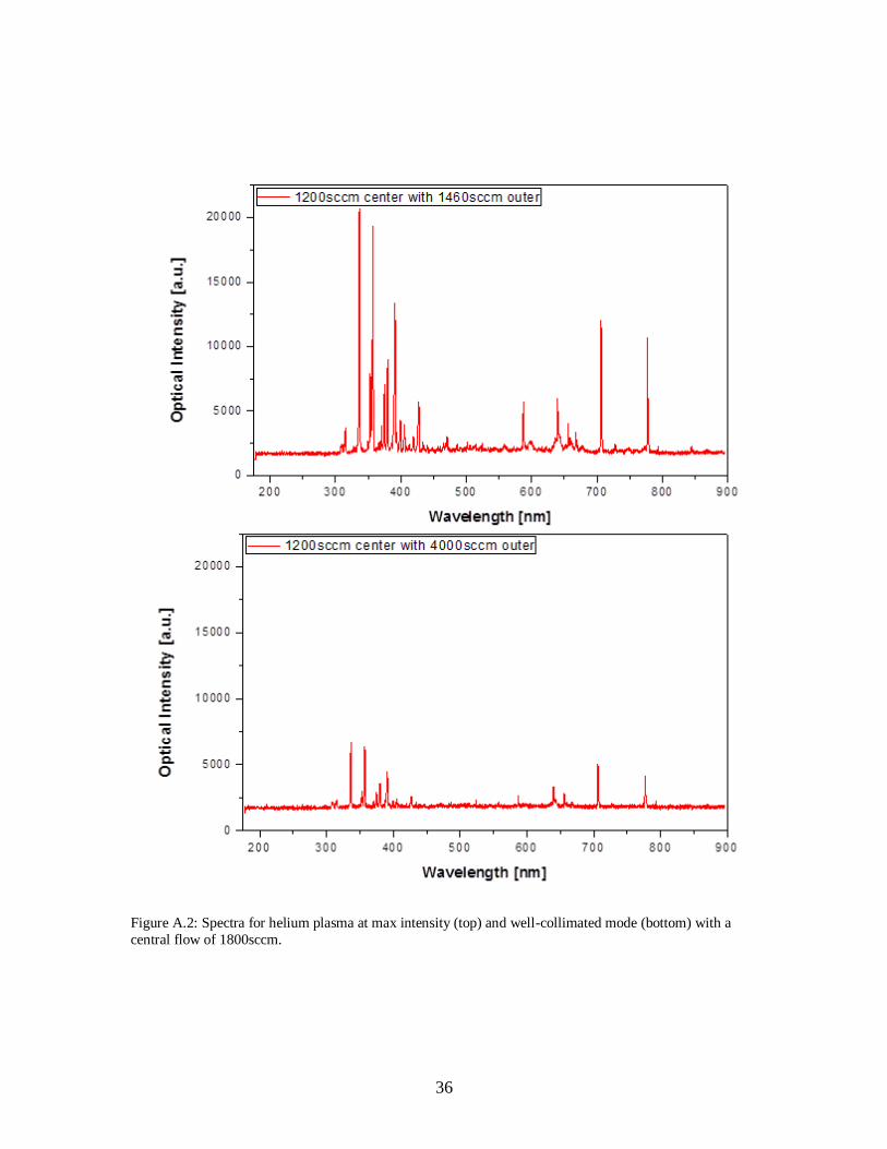
Figure A.1 and Figure A.2 are a complete set of the spectral data obtained for all-
helium plasma.
Figure A.1: Spectra for helium plasma at max intensity (top) and well-collimated mode (bottom)
with a central flow of 600sccm.
36
Figure A.2: Spectra for helium plasma at max intensity (top) and well-collimated mode (bottom) with a
central flow of 1800sccm.

37
Figures A.3 through A.5 are the complete set of the spectral data obtained for the
argon and argon-helium plasma.
Figure A.3: Spectra for single jet argon plasma at 800sccm (top) and 1600sccm (bottom).

38
Figure A.4: Spectra for argon plasma at 800sccm max intensity (top) and 1600sccm max intensity
(bottom) with outer helium flows of 1600sccm and 1800sccm respectively.

39
Figure A.5: Spectra for argon plasma at 800sccm well-collimated (top) and 1600sccm well-
collimated (bottom) with outer helium flows of 4200sccm and 2600sccm respectively.