interaction of x-rays with matter and imaging gocha khelashvili assistant research professor of...
TRANSCRIPT
Interaction of X-rays with Matter and Imaging
Gocha Khelashvili
Assistant Research Professor of Physics
Illinois Institute of Technology
Research Physicist
EXELAR Medical Corporation

The Plan• X-ray Interactions with Matter Used at Imaging Energies Photoelectric Effect Coherent Scattering Incoherent Scattering Refraction Small- and Ultra-small Angle Scattering • Radiography
How does it work? Imaging Parameters and Sources of X-ray contrast Drawbacks of Radiography
• Diffraction Enhanced Imaging (DEI) How does it work? Imaging Parameters and Sources of X-ray contrast Drawbacks of DEI
• Multiple Image Radiography (MIR-Planar Mode) How does it work? Sources of X-ray contrast MIR parameters and images
• MIR Model Based on Discrete Scatterers Multiple scattering series approach and MIR transport equation Solution of MIR transport equation Imaging Parameters
• Laboratory DEI / MIR Machine• Summary
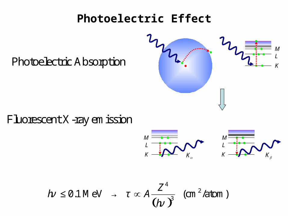
Photoelectric Effect
K
L
M
L
L
KK
MM
Kα Kβ
Photoelectric Absorption
Fluorescent X-ray emission
( )
42
3
0.1 MeV (cm /atom) Z
h Ah
ν τν
≤ → ∝

Thompson (Classical) Scattering
( )2
2 2 150 0 2
11 cos where 2.817 10 m Classical electron radius
2
No energy loss by photon - No recoil by electron.e
d ker r
d m c
σθ −= + = = ×
Ω
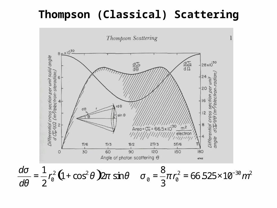
Thompson (Classical) Scattering
( )2 2 2 30 20 0 0
1 81 cos 2 sin 66.525 10
2 3
dr r m
d
σθ π θ σ π
θ−= + = = ×

Rayleigh Scattering (Coherent Scattering)
1 . Photons are scattered by bound electrons
2. Atoms are neither excited or ionized
3. Scattering from different parts of electron cloud - coherent scattering
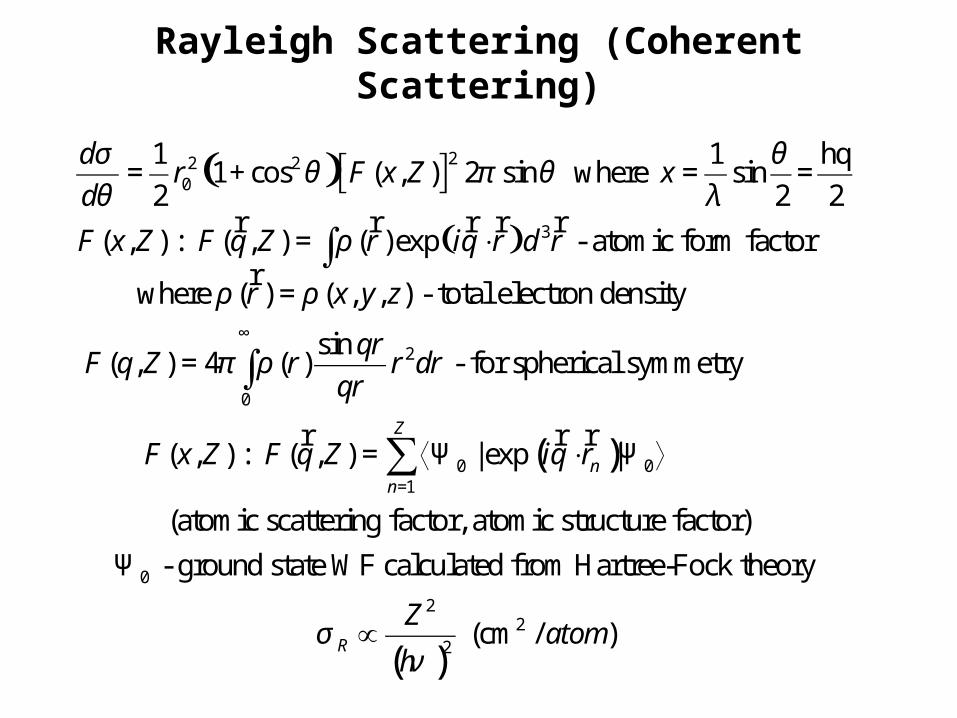
Rayleigh Scattering (Coherent Scattering)
( )[ ]
( )
22 20
3
2
1 1 q1 cos ( , ) 2 sin where sin =
2 2 2
( , ) ( , ) ( ) exp - atomic form factor
where ( ) ( , , ) - total electron density
sin ( , ) 4 ( ) - for spheric
dr F x Z x
d
F x Z F q Z r iq r d r
r x y z
qrF q Z r r dr
qr
σ θθ π θ
θ λ
ρ
ρ ρ
π ρ
= + =
= ⋅
=
=
∫
h
r r r r r:
r
( )
0
0 01
0
al symmetry
( , ) ( , ) |exp |
(atomic scattering factor, atomic structure factor)
- ground state WF calculated from Hartree-Fock theory
Z
nn
F x Z F q Z iq r
∞
=
= ⟨Ψ ⋅ Ψ ⟩
Ψ
∫
∑r r r:
( )
22
2 (cm / )R
Zatom
hσ
ν∝

Compton Scattering (Incoherent Scattering)
1. Energy is transfered to electron
2. Electron recoils from collision
3. Electron considered at rest before collision (No bounding effects)
4. Electron deposits dose in the medium

Compton Scattering (Incoherent Scattering)
( )( )
( ) ( )
2 20
2 20
2 22
2
2
1sin - Klein-Nishina Cross Section
2
11 cos
2
1 cos11
1 (1 cos ) 1 1 cos 1 cos
(in MeV)
0.511
KN
KN
e
d h h hr
d h h h
dr F
d
F
h h
m c
σ ν ν νϕ
ν ν ν
σθ
α θ
α θ α θ θ
ν να
′ ′⎛ ⎞⎛ ⎞= + −⎜ ⎟⎜ ⎟′Ω ⎝ ⎠⎝ ⎠
= + ×Ω
⎧ ⎫−⎧ ⎫ ⎪ ⎪= +⎨ ⎬ ⎨ ⎬
+ − ⎡ ⎤+ − +⎩ ⎭ ⎪ ⎪⎣ ⎦⎩ ⎭
= =

Effects of Binding Energy in Compton (Incoherent) Scattering
1. Electrons are in constant motion in atoms (binding effect)
2. Electrons recoil after collision
3. Energy is transfered to electrons
4. X-ray photon looses part of its energy
inc KNd d
d d
σ σθ θ
= ( )
( )
( ) [ ]
2
0 1
20 0
1 1
,
( , ) ( , ) and ( , ) exp 0
( , ) ( , ) - incoherent scattering function
, |exp ( ) | ( , )
Z
jj
Z Z
m nm n
S x Z
S q Z F q Z S q Z iq r
S x Z S q Z
S q Z iq r r F q Z
εε
ε> =
= =
×
= =⟨ ⋅ ⟩
= ⟨Ψ − Ψ ⟩−
∑ ∑
∑∑
r r r r r
r:
r r r r r

Effects of Binding Energy in Compton (Incoherent) Scattering
( )2
0
11 cos ( , ) 2 sin
2inc KNF S x Z dπ
σ θ π θ θ= + × × ×∫


Radiography Setup

10 KeV are absorbed by primary collimators
Average eneregy of beam increases - "hard" x-rays
penetrate deeper
hν ≤
⇓
⇓

Radiography Setup and Imaging Principles
0
( , , )1( , ) ln AI x y zx y
z Iμ =−
( , )0( , , ) x y z
AI x y z I e μ−=
Double Crystal Monochromator
Si(333)
Object
Radiology Setup
Area Detector
Incident X-ray beam
Attenuation Law Image
z
x
y
A
A
I
I
ΔΣ =Image Contrast
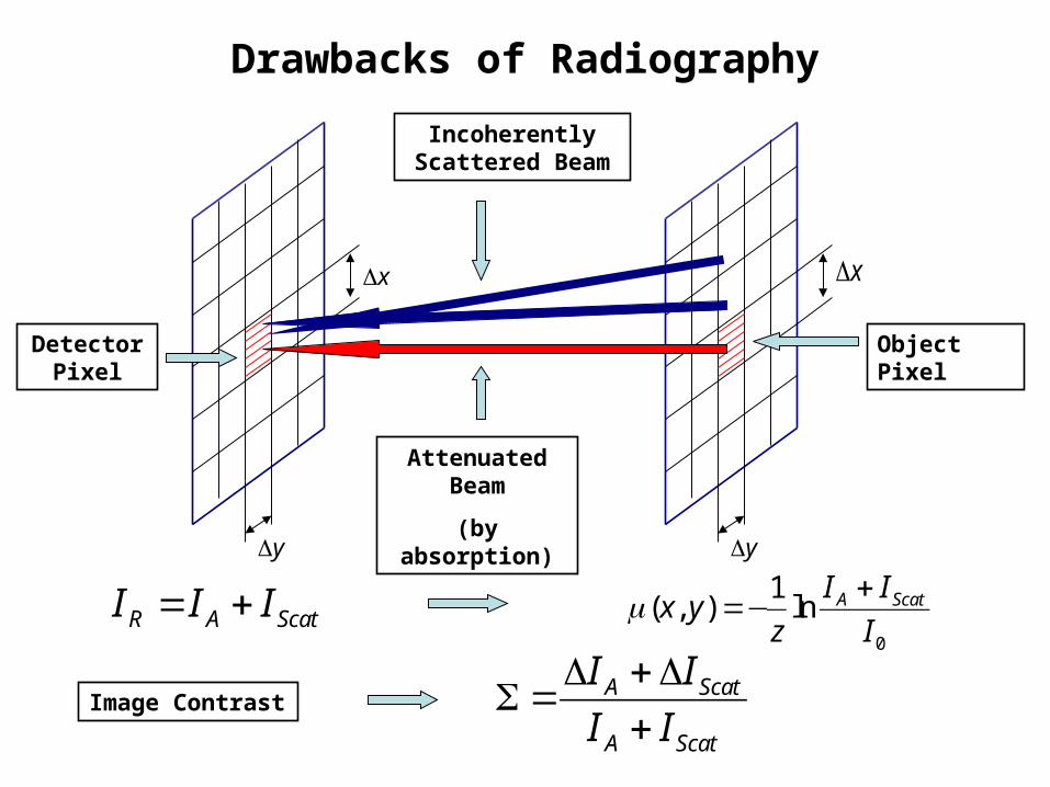
Drawbacks of Radiography
yΔ
xΔ
R A ScatI I I= +
Object Pixel
yΔ
xΔ
Detector Pixel
Attenuated Beam
(by absorption)
Incoherently Scattered Beam
0
1( , ) ln A ScatI Ix y
z Iμ +
=−
A Scat
A Scat
I I
I I
Δ +ΔΣ =
+Image Contrast

DEI Setup and Imaging Principles
z
x
y
Area Detector
Object
Analyzer Crystal Si(333)
DEI Setup
Incident X-ray beam
Double Crystal Monochromator
Si(333)
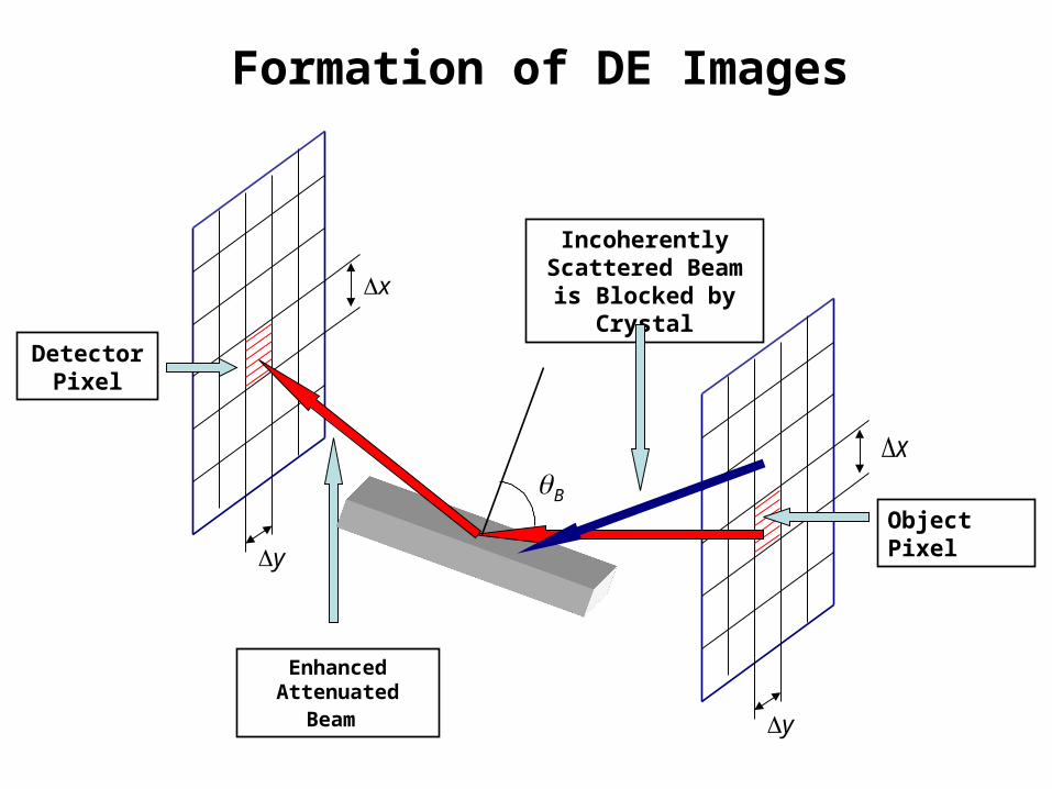
Formation of DE Images
yΔ
xΔ
Object Pixel
yΔ
xΔ
Detector Pixel
Enhanced Attenuated Beam
Incoherently Scattered Beam is Blocked by Crystal
Bθ

1050-10 -5
Low AngleSide
High AngleSide
0.40
0.20
0.00
0.60
0.80
1.00
Analyzer Angle (μradians)
Physics of DEI
Pisano, Johnston(UNC); Sayers(NCSU); Zhong (BNL); Thomlinson (ESRF); Chapman(IIT)
Rel
ati
ve
Inte
nsi
ty
I/I
o
Data from NSLS X27

Calculation of DEI Images
( ) ( ) ( )[ ]L R L Z R L L Z
dRI I R I R
dθ θ θ θ θ
θ= + Δ = + Δ ( ) ( ) ( )[ ]H R H Z R H H Z
dRI I R I R
dθ θ θ θ θ
θ= + Δ = + Δ
( ) ( ) ( )
( ) ( ) ( )( ) ( )
, ( ) , ( ), - Absorption
( ) ( ) ( ) ( )
, ( ) , ( ), - Refraction
, ( ) , ( )
dR dRL H H Ld d
R dR dRL H H Ld d
H L L HZ dR dR
L H H Ld d
I x y I x yI x y
R R
I x y R I x y Rx y
I x y I x y
θ θ
θ θ
θ θ
θ θ
θ θ θ θ
θ θθ
θ θ
−=
−
−Δ =
−
1050-10 -5
Low AngleSide
High AngleSide
0.40
0.20
0.00
0.60
0.80
1.00
Analyzer Angle (μrad)
Re
lati
ve
In
ten
sit
y
I/
Io2D
L B
θθ θ= −2D
H B
θθ θ= +
Dθ

6 1 0 - 0 5 4
Map Conventional DEI
Comparison - Conventional and DEIACR - Phantom
ACR Phantom (Gammex RMI - Model 156) - tumor-like masses, microcalsifications,
cylindrical nylon fibrids 40-45 mm thick compressed breast.
Conventional Radiography - Synchrotron at 18
≈ keV.

DEI image of ACR phantom - smallest calcifications
Data from NSLS X27

Conventional DEI - Absorption DEI - Refraction
Cancer in Breast Tissue
BNL Sept 1997
Pisano, Johnston(UNC); Sayers(NCSU); Zhong (BNL); Thomlinson (ESRF); Chapman(IIT)

Drawbacks of DEI
yΔ
xΔ
Object Pixel
yΔ
xΔ
Detector Pixel

Experimental Evidence of Problems in DEI
0 0( , , ) ( ) ( , , ) ( ) ( , , )I x y I f x y d I f x yθ θ θ θ θ θ θ+∞
−∞
′ ′′ ′ ′ ′= − = ∗∫
( ) ( ) ( ) ( )0 0 1 2I I R Rθ θ θ θ′ =
1235678
Sheets of paper
Lucite substrate
Lucite rod
Alignment target
4
( ) ( ) ( ) ( )0, , , , Ag x y I f x y Rθ θ θ θ′= ∗ ∗

Experimental Results
-1 -0.6 -0.2 0.2 0.6 1x 10
-5
Rod, off-center
x 10-1 -0.6 -0.2 0.2 0.6 1
-5
Thick Paper
200
400
600
-1 -0.6 -0.2 0.2 0.6 1
x 10-5
Background
200
400
600
x 10-1 -0.6 -0.2 0.2 0.6 1
-5
Rod and Paper
200
400
600
( ; , )f x yθ
( ; , )f x yθ
( ; , )f x yθ( ; , )f x yθ
θ
θ
θ
θ
200
400
600

Refraction images Profiles
thick paper
thin paper
no paper
0 50 100 150 200
0
0.2
0.4
0.6
0.8
1
Position (pixels)
MIR
DEIDEI
MIR
DEI

( ) ( )0 0
, 1( , ) ln ln , , - Attenuation Image
T x ya x y f x y d
I Iθ θ
+∞
−∞
⎡ ⎤= − = − ×⎢ ⎥
⎣ ⎦∫
( ) ( )0
, ,( , ) - Refraction Image
( , )
f x y Rr x y d
T x y I
θ θ θ θθ
+∞
−∞
⎡ ⎤= −⎢ ⎥
⎣ ⎦∫


Generalization to CT Reconstruction
zΔ zΔzΔ zΔ
K0
zAI I e μ−=
0I 0I 1 2( )0
N zAI I e μ μ μ− + += K
1μ 2μ 3μ 4μ Nμ
3 11 2 40 0( , , )
N
nn
zzz z z
AI x y z I e e e e I eμ
μμ μ μ =
− Δ− Δ− Δ − Δ − Δ
∑= =K
10
( , ) ln ( , , )N
An
n L
Ip x y z x y z dz
Iμ μ
=
⎛ ⎞=− = Δ =⎜ ⎟
⎝ ⎠∑ ∫
[ ] [ ]( , ) ln ( , , ) ( , , )r r
L L
r x y grad n x y z dz grad x y z dzρ= ∫ ∫:
( , )? ? w x y z:
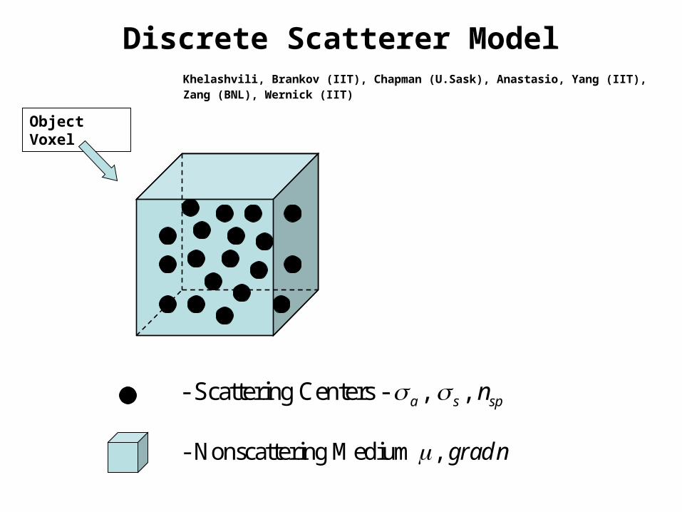
Discrete Scatterer Model
- Scattering Centers - , , a s spnσ σ
Object Voxel
- Nonscattering Medium , grad nμ
Khelashvili, Brankov (IIT), Chapman (U.Sask), Anastasio, Yang (IIT), Zang (BNL), Wernick (IIT)

Multiple Ultra-Small Angle Scattering
Radiation density of x-ray beam in at position in the direction
ˆ (sin cos ,sin sin ,cos )
r
s θ φ θ φ θ=
r
r
ˆ s′r
ˆ sr
• Radiation Transport Theory Approach
ˆ( , ) ( , , ) - Specific IntensityI r s I r θ φ=r r r
dω′
dω
d sr
- particles in volumeds dsρ
( ) ( )( , )- phase function - fraction of the radiation
ˆ ˆscattered from into .
p s s
d s d sω ω
′
′ ′
r r
r r

MIR Radiation Transfer Equation
( ) ˆ4
ˆ ˆ ˆ ˆ ˆ ˆ ˆ ˆ( , ) ( , ) ( , ) ( , ) ( , ) ( , )4n ext
r n ext ss I r s I r s b r s I r s p s s I r s d
π
ρ σρ σ μ ω
π′ ′ ′⋅∇ = − + + ⋅∇ + ∫r r
rr rr r r r r r r r r r r r r
ext a sσ σ σ= +

Ultra-Small Angle Approximation
( )
2
( , , ) ( , , ) ( , , ) ( , , ) ( , , )
( ) ( , , )4
t n ext
n ext
dI z s s I z s I z s b z s I z s
z d s
p s s I z s d s
ρ ρ ρ σ μ ρ ρ ρ
ρ σρ
π
+∞ +∞
−∞ −∞
∂+ ⋅∇ = − + + +
∂
′ ′ ′+ −∫ ∫
rr r r r rr r r r r rr
rr r r r
2
, , sin cos sin sin
t
x y
r zk xi yj zk i j s i jx y
d s ds ds
ρ θ φ θ φ∂ ∂= + = + + ∇ = + = +
∂ ∂
=
r rr r r r r rrr r
r
ln ( , )rb n x y=∇rr r
0 0( , ) x y
n nn x y n x y n n x n y
x y
∂ ∂= + + = + +
∂ ∂

General Solution
[ ]
[ ]
2 22
0
1 1( , , ) exp ( ) exp ( )
(2 ) 2
exp ( ) ( , , ) ( , , )n t
I z s d d q i is q ibq ib z z
is z F z q K z q
ρ κ κ ρ κπ
κ ρ σ μ κ κ
+∞ +∞
−∞ −∞
⎡ ⎤= − ⋅ + ⋅ ⋅ − − ×⎢ ⎥⎣ ⎦
× − − ⋅
∫ ∫r rr r r r rr r r r r
r r rr r r
2 20 0
0
2
( , ) ( , ) exp( )
( , , ) exp ( )4
( ) ( ) exp( )
zn ext
F q I s i is q d d s
K z q P q z dz
P q p s is q d s
κ ρ κ ρ ρ
ρ σκ κπ
+∞ +∞
−∞ −∞
= ⋅ + ⋅
⎡ ⎤′ ′= −⎢ ⎥
⎣ ⎦
= ⋅
∫∫
∫
∫∫
r r r r rr r r r r
r rr r
r r r r r

Phase Function
2( , ) s d
p s sa d
σ σπ
′ =Ω
r r
3 6
2
5
10 10
11 1
2
10
sp e
a
Nn r
V
λ
δ λπ
δ −
≈ −
= − ≈ −
≈
( )
( ) ( )
2 22 2 2 2 2 2
22 2
2 2
02 22 2 2 2 2
4, sin , sin ;
4
4 4 ( , ) ( ) 4 4
4 4
x y x y
s s
ext
d as s s d s ds ds d d d d
d s
dp s s p s W
a d s s
σ δθ θ θ θ φ θ θ φ
δ
σ σσ δ δ
π σ δ δ
= = + = ≈ = = ≈Ω +
′ = ⇒ = =Ω + +
r
r r
aa

Phase Function
2 2
2 2
2
| | ( ) 24 ln 1
( )p
s p s d s
p s d sθ δ
δ⎛ ⎞= = +⎜ ⎟⎝ ⎠
∫∫∫∫
r r
r
( )2 2
20 2
| | ( ) 1( ) 4 exp ,
( )p p
p
s p s d sp s W s
p s d sα α
α= − =∫∫
∫∫
r
r
22
1 12
4 ln 1p
p
αθ δ
δ
= =⎛ ⎞+⎜ ⎟⎝ ⎠
Khelashvili, Brankov (IIT), Chapman (U.Sask), Anastasio, Yang (IIT), Zang (BNL), Wernick (IIT)
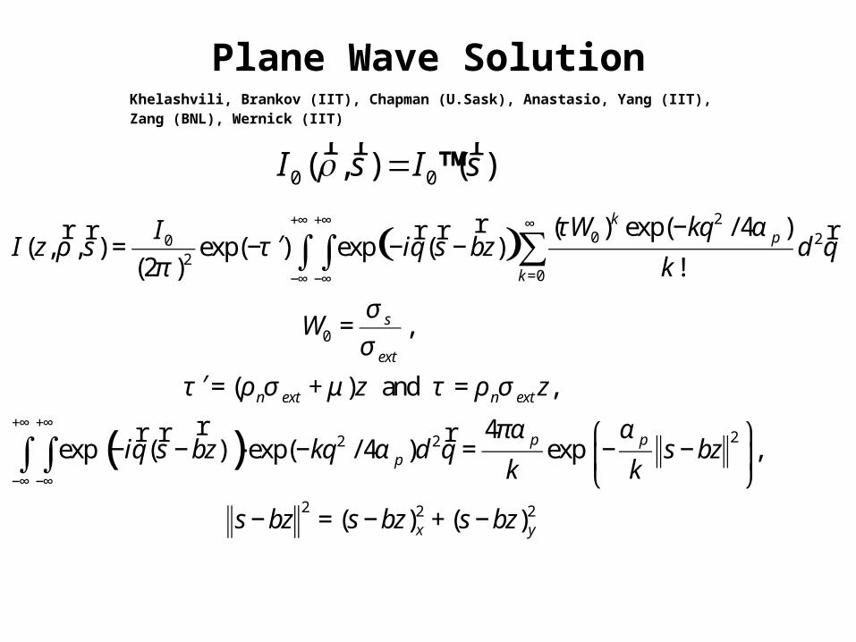
Plane Wave Solution
0 0( , ) ( )I s I sρ = är r r
( )2
0 202
0
0
( ) exp( / 4 )( , , ) exp( ) exp ( )
(2 ) !
,
( ) and ,
exp (
kp
k
s
ext
n ext n ext
W kqII z s iq s bz d q
k
W
z z
iq
τ αρ τ
π
σ
σ
τ ρ σ μ τ ρ σ
+∞ +∞ ∞
=−∞ −∞
−′= − − −
=
′ = + =
−
∑∫ ∫rr r r r r
r( ) 22 2
2 2 2
4) exp( /4 ) exp ,
( ) ( )
p pp
x y
s bz kq d q s bzk k
s bz s bz s bz
πα αα
+∞ +∞
−∞ −∞
⎛ ⎞− ⋅ − = − −⎜ ⎟
⎝ ⎠
− = − + −
∫∫rr r
Khelashvili, Brankov (IIT), Chapman (U.Sask), Anastasio, Yang (IIT), Zang (BNL), Wernick (IIT)
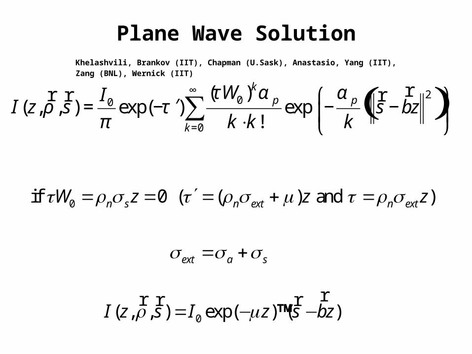
Plane Wave Solution
0
0
if 0 ( ( ) and )
( , , ) exp( ) ( )
n s n ext n ext
ext a s
W z z z
I z s I z s bz
τ ρ σ τ ρ σ μ τ ρ σ
σ σ σ
ρ μ
′= = = + =
= +
= − −ärr r r
Khelashvili, Brankov (IIT), Chapman (U.Sask), Anastasio, Yang (IIT), Zang (BNL), Wernick (IIT)
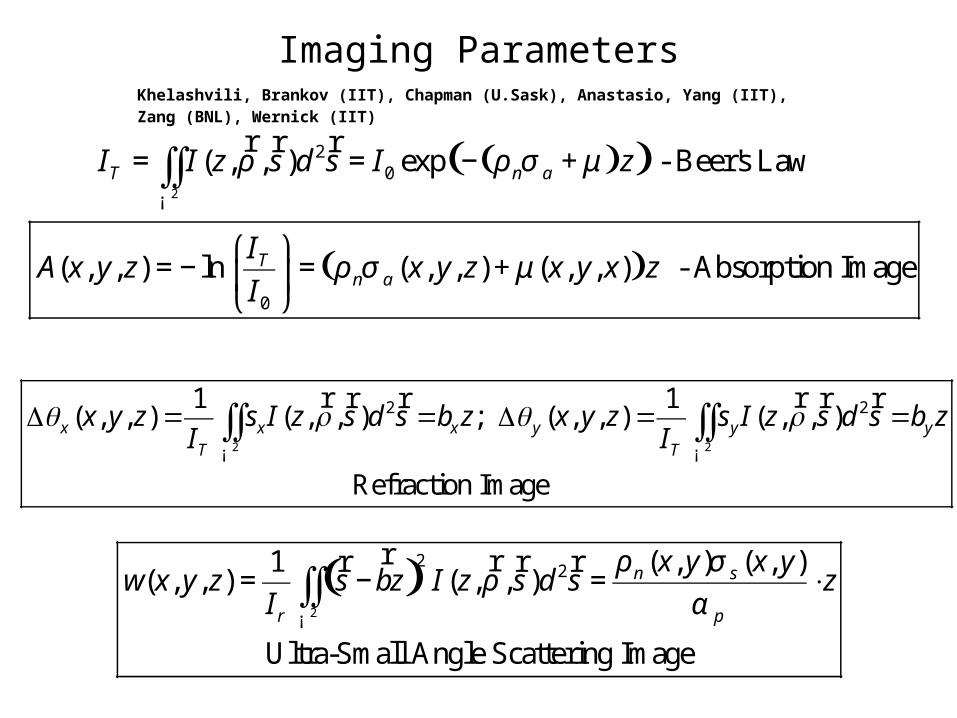
Imaging Parameters
( )( )
( )
2
20
0
( , , ) exp - Beer's Law
( , , ) ln ( , , ) ( , , ) - Absorption Image
T n a
Tn a
I I z s d s I z
IA x y z x y z x y x z
I
ρ ρ σ μ
ρ σ μ
= = − +
⎛ ⎞= − = +⎜ ⎟
⎝ ⎠
∫∫¡
r r r
2 2
2 21 1( , , ) ( , , ) ; ( , , ) ( , , )
Refraction Image
x x x y y yT T
x y z s I z s d s b z x y z s I z s d s b zI I
θ ρ θ ρΔ = = Δ = =∫∫ ∫∫¡ ¡
r rr r r r
( )2
22 ( , ) ( , )1
( , , ) ( , , )
Ultra-Small Angle Scattering Image
n s
r p
x y x yw x y z s bz I z s d s z
I
ρ σρ
α= − = ⋅∫∫
¡
r rr r r
Khelashvili, Brankov (IIT), Chapman (U.Sask), Anastasio, Yang (IIT), Zang (BNL), Wernick (IIT)

Experimental Conformation
Lucite container – wedge shaped.
Polymethylmethacrylate (PMMA) microspheres in glycerin.
Khelashvili, Brankov (IIT), Chapman (U.Sask), Anastasio, Yang (IIT), Zang (BNL), Wernick (IIT)

Experimental ConformationKhelashvili, Brankov (IIT), Chapman (U.Sask), Anastasio, Yang (IIT), Zang (BNL), Wernick (IIT)


labDEI System
Detector
Analyzer
Pre-mono & Mono
X-ray Source
Morrison, Nesch, Torres, Khelashvili (IIT), Hasnah (U. Qatar) Chapman (U.Sask)

1cm
cartilage
bone
Lab DEI System tissue images
Morrison, Nesch, Torres, Khelashvili, Chapman (IIT)Muehleman (Rush Medical College)
Human tissue image using prototype
laboratory DEI system using Mo K
(17.5keV) radiation. Image is of a
section of a knee joint immersed
in formalin showing cartilage.
α

Summary
• First reliable Theoretical Model of DEI – MIR has been developed.
• Model can be used to simulate experiments starting from source, through crystals (this was known), through object (was unknown), through analyzer crystal (partially known – dynamical theory of diffraction – but crystal and beam specific calculations need to be done).
• CT reconstructions – some steps are already taken in this direction – Miles N. Wernick et al “Preliminary study of multiple-image computed tomography”
• CSRRI (IIT) / Nesch LLC – are developing in-lab research DEI instrument

Acknowledgements
Funded by NIH/NIAMS.
L.D. Chapman (Anatomy and Cell Biology, University of Saskatchewan, Canada)
J. Brankov, M. Wernick, Y. Yang, M. Anastasio (Biomed. Engineering, IIT)
T. Morrison and I. Nesch (CSRRI, IIT)
C. Muehleman (Department of Anatomy and Cell Biology, Rush Medical College)