interim advice note 97/07 (ian 97/07) assessment and ... · assessment and upgrading of existing...
TRANSCRIPT

Interim Advice Note 97/07 Assessment and Upgrading of Existing Vehicle Parapets
IAN 97/07 Page 1 of 49 Aug 07
INTERIM ADVICE NOTE 97/07 (IAN 97/07)
Assessment and Upgrading of Existing Vehicle Parapets
SUMMARY This Interim Advice Note:
� Supersedes BA 37/92, “Priority Ranking
of Existing Parapets” and IAN 72/06, “Interim Advice on the Upgrading of Parapets”
� Introduces ALARP based risk ranking tools for existing parapets
� Supplements and partially supersedes TD 19/06, “Requirement for Road Restraint Systems”
� Provides advice on assessment of parapet and safety barrier supporting members on bridges and retaining walls
� Provides advice on substandard parapet connections and transitions

Interim Advice Note 97/07 Assessment and Upgrading of Existing Vehicle Parapets
IAN 97/07 Page 2 of 49 Aug 07
INTERIM ADVICE NOTE 97/07 ASSESSMENT AND UPGRADING OF EXISTING VEHICLE PARAPETS
CONTENTS
Section Description Page No. 1. Introduction .................................................................................................3
2. Scope..........................................................................................................4
3. Implementation............................................................................................5
4. ALARP Based Risk Assessment Framework...............................................6
5. Risk Assessment of Existing Parapet Sites .................................................8
6. Assessment of Parapet Remnant Containment Capacity ..........................11
7. Upgrading of Existing Parapets .................................................................15
8. Obsolete/Substandard Parapet Connections and Transitions....................18
9. List of Documents to be Withdrawn/Amended ...........................................21
10. Contacts....................................................................................................22
11. References................................................................................................23
Appendix A: ALARP Based Risk Ranking Tools ............................................................24
Appendix B: Incursion Risk Ranking Tools ....................................................................28
Appendix C: Identification of Substandard BACO Parapets ...........................................46
Appendix D: Assessment of Parapet Supporting Members............................................48

Interim Advice Note 97/07 Assessment and Upgrading of Existing Vehicle Parapets
IAN 97/07 Page 3 of 49 Aug 07
INTERIM ADVICE NOTE 97/07 ASSESSMENT AND UPGRADING OF EXISTING VEHICLE PARAPETS
1. Introduction 1.1 Interim Advice Note 72/06, “Interim Advice on the Upgrading of Existing Parapets”, now superseded by this Interim Advice Note, improved previous assessment and upgrading guidance by providing advice in the following areas:
� The use of DfT17 and TRL18 incursion risk ranking tools to provide criteria for identifying sites requiring upgrading with very-high containment (H4a) road restraint systems.
� Amendments to BA 37/92, “Priority Ranking of Existing Parapets”, to be consistent with the IRRRS, Interim Requirements for Road Restraint Systems (now superseded by TD 19/06), and the incursion risk ranking tools, to enable a consistent risk assessment approach.
1.2 This Interim Advice Note (IAN) revises the previous advice to be consistent with the risk-theory based approach of TD 19/06, “Requirement for Road Restraint Systems”, whilst enabling significant cost and programme related benefits, and reduced congestion. Additional and expanded advice is provided in the following areas:
� Guidance which supplements and partially supersedes TD 19/06. � The incursion risk ranking tools are brought together in a single Appendix, which also
includes advice for the single carriageway road over road risks, not previously covered by IAN 72/06.
� The introduction of ALARP based risk ranking tools, which supersede the BA 37/92 priority ranking framework.
� Assessment of parapet supporting members and safety barrier supporting members on bridges and retaining walls.
� Assessment of obsolete/substandard parapet connections and transitions. � Identification and assessment of substandard BACO parapets. � A consistent risk based approach, using incursion and ALARP based risk ranking
tools, and the TD 19/06 Road Restraint Risk Assessment Process (RRRAP), to enable realistic risk levels to be ascertained together with associated upgrading advice.
1.3 This IAN does not cover risks associated with bridges/structures over or adjacent to high risk facilities (e.g. schools, chemical plants) or risks associated with on-deck vehicle collision with main structural members of bridges (e.g., half-through girders). The Highway Agency’s Vehicle Restraints and Risk Management Team should be consulted for advice on assessing these types of risks.

Interim Advice Note 97/07 Assessment and Upgrading of Existing Vehicle Parapets
IAN 97/07 Page 4 of 49 Aug 07
2. Scope This IAN should be used for all proposals to assess or upgrade existing parapets or parapet connections, on Agency-owned structures. It is similarly applicable where carriageway widening or realignment proposals increase the likelihood of vehicle collision with existing parapets. This document should be read in conjunction with TD 19/06, which is supplemented and partially supplemented by this advice. This IAN is also applicable for maintenance works or carriageway widening/realignment works carried out during Targeted Programme of Improvement (TPI) projects.

Interim Advice Note 97/07 Assessment and Upgrading of Existing Vehicle Parapets
IAN 97/07 Page 5 of 49 Aug 07
3. Implementation This IAN should be used on all schemes, except for those already under construction or those currently being prepared where there would be significant additional cost or delay caused by its use. Refer to TD 19/06 clauses 1.41 to 1.44 for the terminology, definitions and abbreviations relevant to this IAN.
Interim Advice Note 97/07 Assessment and Upgrading of Existing Vehicle Parapets
IAN 97/07 Page 6 of 49 Aug 07
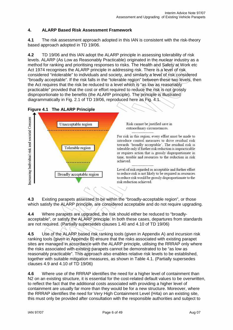
4. ALARP Based Risk Assessment Framework 4.1 The risk assessment approach adopted in this IAN is consistent with the risk-theory based approach adopted in TD 19/06. 4.2 TD 19/06 and this IAN adopt the ALARP principle in assessing tolerability of risk levels. ALARP (As Low as Reasonably Practicable) originated in the nuclear industry as a method for ranking and prioritising responses to risks. The Health and Safety at Work etc Act 1974 recognises the ALARP principle in addressing risk. There is a level of risk considered “intolerable” to individuals and society, and similarly a level of risk considered “broadly acceptable”. If the risk falls in the “tolerable region” between these two levels, then the Act requires that the risk be reduced to a level which is “as low as reasonably practicable” provided that the cost or effort required to reduce the risk is not grossly disproportionate to the benefits (the ALARP principle). The principle is illustrated diagrammatically in Fig. 2.1 of TD 19/06, reproduced here as Fig. 4.1. Figure 4.1 The ALARP Principle
4.3 Existing parapets assessed to be within the “broadly-acceptable region”, or those which satisfy the ALARP principle, are considered acceptable and do not require upgrading. 4.4 Where parapets are upgraded, the risk should either be reduced to “broadly-acceptable”, or satisfy the ALARP principle. In both these cases, departures from standards are not required. (Partially supersedes clauses 1.40 and 4.10 of TD 19/06) 4.5 Use of the ALARP based risk ranking tools (given in Appendix A) and incursion risk ranking tools (given in Appendix B) ensure that the risks associated with existing parapet sites are managed in accordance with the ALARP principle, utilising the RRRAP only where the risks associated with existing parapets cannot be demonstrated to be “as low as reasonably practicable”. This approach also enables relative risk levels to be established, together with suitable mitigation measures, as shown in Table 4.1. (Partially supersedes clauses 4.9 and 4.10 of TD 19/06) 4.6 Where use of the RRRAP identifies the need for a higher level of containment than N2 on an existing structure, it is essential for the cost-related default values to be overwritten, to reflect the fact that the additional costs associated with providing a higher level of containment are usually far more than they would be for a new structure. Moreover, where the RRRAP identifies the need for Very High Containment Level (H4a) on an existing site, this must only be provided after consultation with the responsible authorities and subject to

Interim Advice Note 97/07 Assessment and Upgrading of Existing Vehicle Parapets
IAN 97/07 Page 7 of 49 Aug 07
prior approval of the Technical Approval Authority. (Partially supersedes clauses 2.34 and 4.9 of TD 19/06) Table 4.1 Risk Levels, ALARP and Risk Mitigation
Risk Level Relative Risk (ALARP) Risk Mitigation
High ALARP requires H4a upgrade Upgrade to H4a
Medium1 ALARP requires H1/H2 upgrade Upgrade to H1/H2
Low1 ALARP requires N1/N22 upgrade Upgrade to N1/N22
Very Low Existing parapet is ALARP Monitor Risk3
Negligible Existing risk is “broadly acceptable” Do Nothing
Notes: 1. Existing parapets with remnant capacities less than the required pedestrian level of containment should be considered as high risk, requiring upgrading to appropriate containment levels determined by ALARP. 1. N1 or N2 dependent on TD 19/06 minimum design containment requirements. 2. No mitigation is required but the risk should be monitored against ALARP.
4.7 Where schemes are “notifiable” under the CDM regulations, the results of ALARP based risk assessments carried out in the design of parapet upgrading works should be included as part of the Health and Safety documentation required under the CDM Regulations. For tendered schemes this will be prior to invitation to tender; for Early Contractor Involvement (ECI) schemes and Design and Build (D&B) or Design Build Finance Operate (DBFO) schemes, prior to commencement of construction; and for term maintenance and framework contracts, prior to issue of the works order or task order to the Contractor. (Partially supersedes clauses 1.25 and 1.29 of TD 19/06)

Interim Advice Note 97/07 Assessment and Upgrading of Existing Vehicle Parapets
IAN 97/07 Page 8 of 49 Aug 07
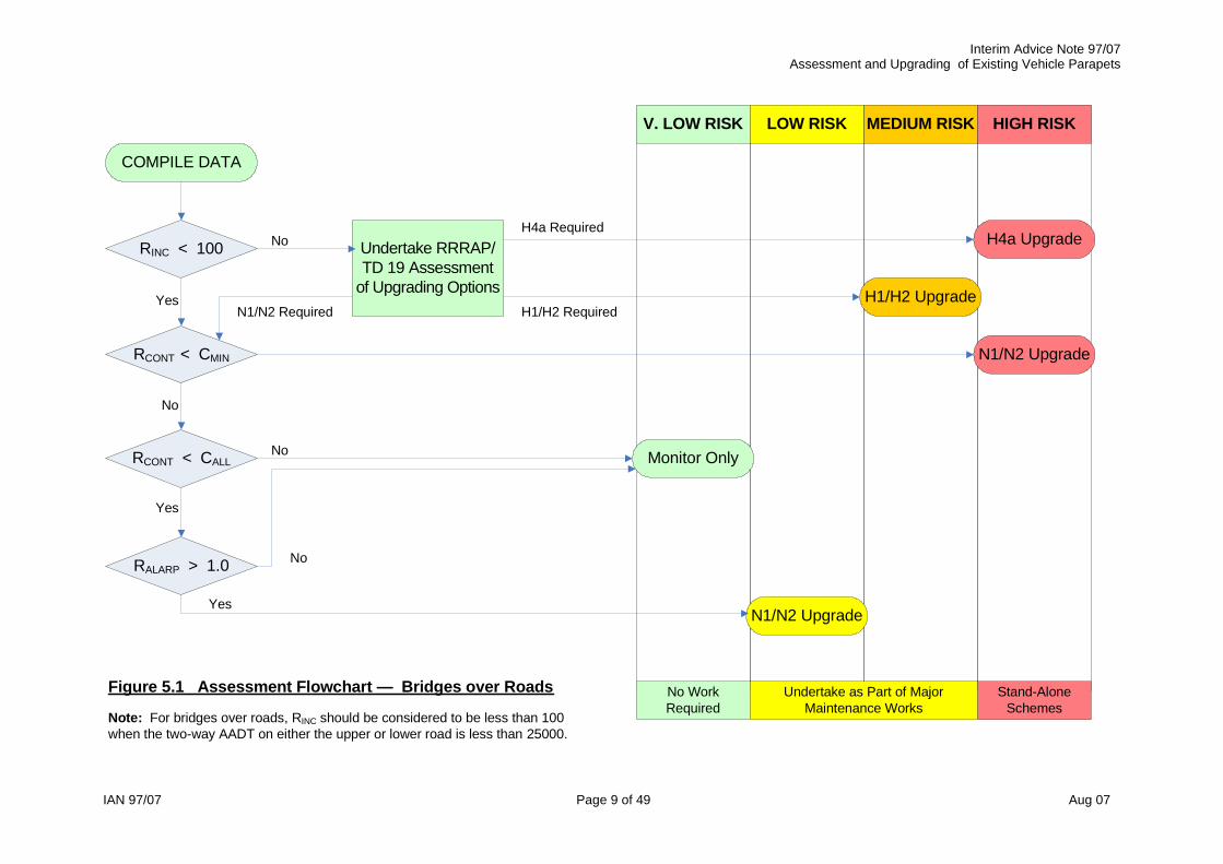
5. Risk Assessment of Existing Parapet Sites 5.1 The ALARP based risk assessment process is illustrated by the flowcharts in figures 5.1 and 5.2 for bridges over roads and bridges over railways respectively. Note that the road-over-road incursion tools do not apply when the two-way AADT on the upper or lower road is less than 25000. 5.2 The flowcharts should also be used for retaining walls supporting roads. However, the incursion risk ranking tools only apply when it is considered possible for a parapet penetrating vehicle (or associated debris) to foul the lower route (railway or road). In these exceptional circumstances, the incursion risk ranking tools for bridges given in Appendix B should be used. 5.3 The flowcharts should also be used for bridges over, and retaining walls adjacent to, rivers, canals and NMU/agricultural access routes. However, the incursion risk ranking tools do not apply. Where it is considered that that there is a very high risk to pedestrians, the HA’s Vehicle Restraints and Risk Management Team should be consulted for advice in assessing this type of risk. 5.4 To use the risk process flowcharts, the following parameters need to be defined:
RALARP ALARP based risk ranking score. (Ref. Appendix A, sections A2 or A4) RINC Incursion risk ranking score for the highest scoring corner.
(Ref. Appendix B) RCONT Remnant capacity of the parapet (expressed as a proportion of the
required capacity, CREQ). Refer to section 6 for guidance. CALL Allowable capacity of the parapet as defined in equation 5.1.
(expressed as a proportion of the required capacity, CREQ). CMIN Minimum capacity of the parapet as defined in equations 5.2 and 5.3.
(expressed as a proportion of N2 containment, or N1 containment) CREQ Required capacity of the parapet as defined in table 5.1. (expressed as
a proportion of N2 containment)
CALL = 0.67•CREQ … (Equation 5.1) For non-rail bridges/structures,
CMIN = 0.15•N2 (or 0.30•N1) … (Equation 5.2) For railway bridges/structures,
CMIN = 0.50•N2 … (Equation 5.3) Table 5.1 Required Containment Capacity, CREQ (as Proportion of N2)
Speed limit (mph) Bridge/Structure over or adjacent to: 70 60 50 40 302
Railway 1.00•N2 at all speed limits Road or Other1 1.00•N2 0.73•N2 0.50•N2 0.33•N2 0.20•N2 Notes: (1) Other refers to river, canal, NMU/agricultural access routes, open land, etc.
(2) A speed limit of 30mph should be assumed for accommodation bridges. (3) Speed limit on roundabouts should be assumed not to exceed 40mph.
Interim Advice Note 97/07Assessment and Upgrading of Existing Vehicle Parapets
IAN 97/07 Page 9 of 49 Aug 07
RINC < 100
COMPILE DATA
RALARP > 1.0
RCONT < CMIN
RCONT < CALL
Undertake RRRAP/TD 19 Assessment
of Upgrading Options
N1/N2 Upgrade
H4a Upgrade
H1/H2 Upgrade
Monitor Only
N1/N2 Upgrade
No WorkRequired
Stand-AloneSchemes
Undertake as Part of MajorMaintenance Works
V. LOW RISK MEDIUM RISK HIGH RISKLOW RISK
Yes
Yes
No
No
No
No
Yes
H4a Required
H1/H2 RequiredN1/N2 Required
Figure 5.1 Assessment Flowchart — Bridges over Roads
Note: For bridges over roads, RINC should be considered to be less than 100when the two-way AADT on either the upper or lower road is less than 25000.

Interim Advice Note 97/07Assessment and Upgrading of Existing Vehicle Parapets
IAN 97/07 Page 10 of 49 Aug 07
RINC < 100
COMPILE DATA
RALARP > 1.0
RCONT < CMIN
RCONT < CALL
N2 Upgrade
H4a Upgrade
Monitor Only
N2 Upgrade
No WorkRequired
Stand-AloneSchemes
Undertake as Part of MajorMaintenance Works
V. LOW RISK MEDIUM RISK HIGH RISKLOW RISK
Yes
Yes
No
No
No
No
Yes
Figure 5.2 Assessment Flowchart — Bridges over Railways
Note: Assessors should also consider the guidance included within the DfTreport, “Managing the accidental obstruction of the railway by road vehicles”.

Interim Advice Note 97/07 Assessment and Upgrading of Existing Vehicle Parapets
IAN 97/07 Page 11 of 49 Aug 07
6. Assessment of Parapet Remnant Containment Capacity Historical Background 6.1 Parapets may be classified fundamentally into those which were built before the advent of design criteria based on containment in 1967, and those which have been built since that date. Most pre-1967 parapets have since been replaced or protected. 6.2 Pre-1967 parapets include a large number of masonry and brick parapets, generally associated with masonry arch bridges. These rely principally on their mass to keep the stresses in the mortar layers compressive under light to moderate impact loadings. They cannot be relied on to contain heavier vehicles travelling at speed, and secondary incidents may be initiated by falling debris. Many masonry parapets have been upgraded by providing a reinforced concrete stem which may have been integral with a horizontal slab spanning all or part of the way transversely across the bridge. Such reinforced concrete parapets may have been clad with masonry or brick slips to retain their original appearance. Where masonry and brick parapets have been provided on older types of bridges other than masonry arch structures, the problems of upgrading have been similar to those described in clause 6.3. 6.3 Pre-1967 bridges, other than arches, often had a variety of parapet types, including wrought iron, cast iron, steel, timber, masonry, in situ and precast concrete. The superstructures of these bridges may not have sufficient capacity to transmit the impact forces from parapets of modern containment standards, and, unlike arch bridges, may not have sufficient reserves of dead load capacity to allow additional strengthening members to be added to the structure. Consequently, upgrading has often comprised provision of protective safety barriers, or, more rarely, modifications to the structure. 6.4 Parapets built since 1967 (or earlier parapets known to be designed to BE5) were designed to standards which may be considered as broadly equivalent to current standards in terms of containment characteristics. Such parapets should be considered as acceptable unless there are known faults, as listed below:
� parapets demonstrated to be incorrectly designed or constructed, e.g., some early parapets were detailed without proper continuity in the longitudinal members;
� parapets designed to lower containment criteria than would be required by current standards;
� parapets which have exhibited significant deterioration; this includes steel members which have corroded and parapet fixings, to the extent that there has been a significant loss of design capacity;
� parapets with other known material problems, including embrittlement in certain earlier aluminium parapet types;
� parapets which have been damaged and have not been satisfactorily repaired, where there would be significant loss of design capacity.
Evaluation of Remnant Containment Capacity 6.5 The containment capacity of existing masonry parapets should be assessed in accordance with BS 6779-4. 6.6 The strength of pre-1967 parapets should generally be assessed on the basis of engineering judgement. To help in this process, it may be appropriate to carry out occasional strength checks based principally on the resistance of the existing parapet. In this regard BS 6779 parts 1 to 3 should be consulted, for metal, concrete and combined metal/concrete parapets respectively. Note that the additional design requirements for concrete and

Interim Advice Note 97/07 Assessment and Upgrading of Existing Vehicle Parapets
IAN 97/07 Page 12 of 49 Aug 07
combined metal concrete parapets given in clauses 4.55 to 4.61 of TD 19/06 should not be considered in the assessment of existing parapets. (Partially supersedes clauses 4.55 to 4.61 of TD 19/06) (Note that the material factors used in BS 6779 parts 2 to 4 are considerably less than those used in BS 5400, resulting in significantly increased calculated resistances. Consequently, formulae and charts developed for the use of BS 5400 may not be applicable to the assessment of parapets) 6.7 Parapets with known faults built since 1967 should generally be assessed on the basis of engineering judgement, considering the likely loss of the as-built capacity caused by known faults and defects. Where this approach proves impractical, the approach for assessing pre-1967 parapets, given in clause 6.6 may be applied. 6.8 Parapet supporting members built since 1967 should generally be considered as acceptable for assessment purposes, providing there are no apparent errors in reinforcement detailing. Supporting members for parapets installed before 1967 and any supporting members with apparent detailing errors should be assessed on the basis of engineering judgement. To help in this process, it may be appropriate to carry out occasional strength checks. For metal parapets, assessment should be based on the absolute minimum strength assessment criteria given in Appendix D. For other types of parapets, assessment should be based on the design criteria for parapet supporting members given in clause 6.7 of BD 37/01 but assuming unit values for γfl and γf3. (Partially supersedes clause 4.46 of TD 19/06) 6.9 The strength of attachment and anchorage systems should be assessed on the basis of engineering judgement. Cast in cradles and drilled-in resin bonded anchors for parapets built since 1967 are generally reliable, whereas drilled-in expanding anchors are less likely to be reliable. Socketed posts of parapets built since 1967 may generally be considered to be reliable providing that embedment lengths appear to be adequate, and there are no signs of significant deterioration to the posts, sockets, or supporting members. Attachment and anchorage systems to pre-1967 metal parapets should be assessed against the absolute minimum strength assessment criteria given in Appendix D, assuming unit values for γfl and γf3. Other pre-1967 parapet types, should be assessed against the criteria given in BS 6799 parts 1 to 3, but assuming unit values for γfl and γf3. (Partially supersedes clause 4.62 of TD 19/06) 6.10 Parapets with drilled-in expanded anchors should be assessed in accordance with clauses 6.6 and 6.7, but with maximum remnant containment levels of 0.50•N2 for N2 parapets and 0.25•N2 for N1 parapets. 6.11 Spalling resulting from vehicle impact to parapets should normally be considered to represent a negligible safety risk, as both the probability of occurrence and the additional consequences are generally low. (e.g., secondary spalling related to parapet stringcourse damage occurs concurrently with possible incursion/debris from vehicle and parapet components, so the risk of a secondary accident below the structure would not normally be significantly increased) This type of risk should generally be ignored when assessing existing parapet sites for potential upgrading. 6.12 Where parapets are protected by safety barriers which comply with either TD 19/06 or the NPSBS (Rev. 1), they should be considered as acceptable for assessment purposes unless the parapet is not capable of providing pedestrian containment. 6.13 Where protective safety barriers are provided with working widths less than required by TD 19/06 or the NPSBS (Rev. 1), they should be considered as substandard. Where the speed limit is less than 50mph, or the two-way traffic flow is less than 7000, the risk should

Interim Advice Note 97/07 Assessment and Upgrading of Existing Vehicle Parapets
IAN 97/07 Page 13 of 49 Aug 07
generally be considered to be negligible. Outside these limits, risks should be assessed using the ALARP based risk assessment tool for substandard protective safety barriers included in Appendix A. Any upgrading work justified should be carried out as part of major maintenance, or as part of a TPI. 6.14 The assessment and upgrading of obsolete/substandard parapet connections and transitions is covered in section 8. Assessment of Steel Parapets 6.15 As-built post-1967 steel N2 and N1 parapets may be assumed to have effective containments of 1.50•N2 and 0.75•N2 respectively, except for N1 vertical rod infill parapets where an effective containment of 0.33•N2 should be assumed. Assessed capacities should reduce as-built values when there is significant deterioration or defects. 6.16 As-built steel normal containment parapets may be considered as roughly equivalent to H1/H2 containment, with regard to the potential to prevent incursion. Where the loss of condition of such parapets does not reduce the containment capacity by more than 20% from the as-built value, H1/H2 containment may be assumed when a RRRAP or similar risk assessment is undertaken. Assessment of Aluminium Parapets 6.17 As-built post-1967 Aluminium N2 and N1 parapets may generally be assumed to have effective containments of 1.00•N2 and 0.50•N2 respectively. Assessed capacities should reduce as-built values when there is significant deterioration or defects. 6.18 As-built substandard BACO N2 and N1 parapets may be assumed to have effective containments of 0.50•N2 and 0.25•N2 respectively. Assessed capacities should reduce as-built values when there is significant deterioration or defects. 6.19 Substandard BACO parapets should be considered for assessment and upgrading as for other substandard parapets, based on the assumptions of remnant containment given in clause 6.18. Appendix D provides guidance on the identification of substandard BACO parapets.
6.20 CHE Memoranda 30/96 and 44/97 (and Addendum No. 1) recommended that parapets supplied by Lindley between 1994 and 1996 be inspected to find out whether the rails were from an unacceptable source (Hulett). Any rails identified as Hulett were to be replaced and details recorded. It is likely that all such defective rails have now been replaced. However, if it is suspected that Lindley parapets from this period still have defective rails, the Highway Agency’s Vehicle Restraints and Risk Management Team should be consulted for advice. Assessment of Vehicle Parapets within Carriageway Widening/Realignment Schemes 6.21 Where carriageway widening/realignment schemes allow the possibility of retaining existing parapets, the parapets should be assessed in relation to the proposed carriageway alignment. 6.22 Where carriageway widening/realignment schemes allow both the possibility of retaining existing parapets and their protective safety barriers, the following two options should be considered for assessment:

Interim Advice Note 97/07 Assessment and Upgrading of Existing Vehicle Parapets
IAN 97/07 Page 14 of 49 Aug 07
� Consider retaining both parapet and protective safety barrier, and assess in relation to the proposed carriageway alignment. (Only viable where the safety barrier has significant residual life)
� Consider retaining the parapet and removing the protective safety barrier, and assess in relation to the proposed carriageway alignment. (Only viable where the redundant capacity of the parapet satisfies the containment criteria for upgrading to high risk sites given in clause 7.5.)
Where both options satisfy the assessment criteria, the former option should generally be preferred provided that this does not necessitate significantly reduced lane widths and/or setback. In this context, "significant" means values that are not considered to be acceptable as departures from TD 27/05, after consultation with the HA SSR Safe Road Design Team. Temporary or Interim Protection of Substandard Parapets. 6.23 Temporary protection during road works or longer term interim protection of sub-standard parapets should only be considered where there are exceptional circumstances, subject to agreement by the Technical Approval Authority.

Interim Advice Note 97/07 Assessment and Upgrading of Existing Vehicle Parapets
IAN 97/07 Page 15 of 49 Aug 07
7. Upgrading of Existing Parapets General Principles 7.1 Some of the general principles relating to the remedial work on substandard parapets are described below. Any remedial work required for the substandard parapets should be assessed and considered individually for each structure. It is important that the work of upgrading substandard parapets is co-ordinated with other work so as to minimize costs and disruption to traffic. 7.2 The primary function of a parapet is to provide vehicle containment together with safe redirection. However, special consideration must be given to how this can be achieved in structures which are listed or are of historic importance without destroying the character of these structures. In these cases, the Technical Approval Authority should be consulted at an early stage. 7.3 Among the available methods of upgrading existing parapets, the following options should be considered:
(i) Remove old parapet and replace with a new one to current standard; (ii) Strengthen existing system by like-for-like replacement of existing
faulty/deteriorated components (e.g. posts, rails, fixings); (iii) Provide an additional independent containment facility. This option is only viable if
there is sufficient room available to allow for an installation which provides adequate setback and working width. The facility will generally be acceptable in the long term provided that the substandard parapet is adequate for pedestrian containment.
7.4 Where existing parapets are to be upgraded, the required level of containment should be determined from the risk assessment process given in section 5, subject to the following minimum containment levels:
� N2 for any parapets on roads with speed limit of 50mph or more, or on any road over or adjacent to a railway.
� N1 for parapets on roads with speed limit of less than 50mph, other than on roads over or adjacent to railways
The existing approach and departure safety barriers should also be upgraded, where necessary, to ensure compliance with TD 19/06 and the RRRAP. The containment level of the safety barrier should generally not exceed the required containment level of the parapet as determined by this IAN. In particular, opportunity should be taken to ensure “length of need” and P4 terminal requirements are addressed. 7.5 In addition to the requirements of clause 7.4, for the following types of structures, containment levels of new parapets should be no less than the as-built containment level of the existing parapets:
� Bridges over or retaining walls adjacent to railway lines. � Bridges over or retaining walls adjacent to roads, where the two-way AADT values for
the road above and the road below both exceed 25000. � Viaducts longer than 100m carrying roads with two-way AADT exceeding 25000.
Where the existing parapets to these structures are steel N2 containment parapets, it is necessary to replace with a minimum containment level of N2 for steel parapets, or H1/H2 for other parapet types.

Interim Advice Note 97/07 Assessment and Upgrading of Existing Vehicle Parapets
IAN 97/07 Page 16 of 49 Aug 07
7.6 The assessment and upgrading of obsolete/substandard parapet connections and transitions is covered in section 8. Parapet Supporting Members on Existing Bridges and Retaining Walls 7.7 Before upgrading existing vehicle parapets, the parapet supporting member must be checked to ensure that there is adequate strength to resist vehicle collision loads. Refer to Appendix D for the loading requirements applicable to upgrading. 7.8 Where parapet supporting members are unable to satisfy the vehicle collision load criteria given in Appendix D, the following additional options should be considered:
� Provide a continuous panel type safety barrier, near the edge of the deck or the face of the retaining wall, instead of a parapet. (Ref. clauses 7.12 and 7.13)
� Provide an additional protective safety barrier with appropriate setback and working width. (Ref. Clauses 7.11 to 7.13)
7.9 Where the alternative options given in 7.8 prove impractical or disproportionately expensive a further option of allowing a partial reduction of the Appendix D loading requirements may be considered, subject to the submission of a departure from standards. The submission should demonstrate that the proposed solution satisfies the ALARP principle. (i.e., by demonstrating that the costs and effort involved in complying with clause 7.7 would be grossly disproportionate to the benefits) 7.10 TD 19/06 requires existing parapet supporting members to be assessed for anchor related concrete cone failure and concrete splitting, when parapets are to be upgraded. Parapet supporting members able to satisfy the minimum strength assessment criteria should have a sufficient density of reinforcement in the parapet stringcourses (longitudinal bars and links) to make concrete cone failure or concrete splitting unlikely. Consequently, as the containment requirement for the parapet should not be significantly affected, there should be no requirement to check for these types of anchor failure. (Partially supersedes clause 4.68 of TD 19/06) Safety Barrier Supporting Members on Existing Bridges 7.11 Members supporting post and rail type safety barriers should be considered as acting as parapet supporting members. (Ref. clauses 7.7, 7.9, 7.10 and 7.13 to 7.18) 7.12 Continuous panel type safety barriers often act as chains when impacted. A safety barrier may be considered as chain-like if either of the following conditions apply:
� The safety barrier is not bolted to a supporting member. � The density of anchorage bolts provided along the barrier is less than 200mm2/m.
(i.e., cross-sectional area of bolts per m length of barrier) Members supporting chain-like safety barriers should consider the design criteria given in clause 7.13. For other continuous panel type safety barriers, the design criteria given in clause 7.11 should apply.

Interim Advice Note 97/07 Assessment and Upgrading of Existing Vehicle Parapets
IAN 97/07 Page 17 of 49 Aug 07
7.13 Members supporting chain-like safety barriers do not require consideration of the local effects of vehicle collision. For supporting members of this type the following criteria apply:
� For members supporting very high containment (H4a) safety barriers and higher containment (H1/H2) rigid concrete barriers, consider both the global effects of vehicle collision given in section D4 of Appendix D, and any specific assessment criteria recommended by the parapet manufacturer.
� Where it is proposed to provide a safety barrier near the edge of a bridge deck, the clearance from the back face of the barrier to the edge of the deck should comply with the safety barrier manufacturer’s recommendations. Where this would result in a ledge more than 300mm wide, additional suitable mitigation measures are required to prevent access to the ledge, subject to the approval of both the safety barrier manufacturer and the Technical Approval Authority. The minimum height and infill requirements for parapets required by TD 19/06 must also be satisfied. Safety barriers which rely on embedment are generally not suitable for such usage.
� Where anchorages are required for chain-like safety barriers, they should ideally comply with clauses 4.63 to 4.69 of TD 19/06 (assuming nominal bolt forces equal to the ultimate tensile capacity of the bolts specified by the manufacturer). Where compliance with this requirement would require structural modifications to the existing structure, it is preferable to accept the highest level of anchorage capacity which does not necessitate structural modifications, subject to the minimum recommended requirements of the manufacturer being met, and subject the approval of the Technical Approval Authority.
Anchorage Systems for Parapets 7.14 It is important to make use of existing anchors wherever possible, as this will tend to be significantly more cost-effective and less disruptive than installing new anchors. 7.15 Where parapets are upgraded, existing drilled-in expanding anchors should be replaced by new cast-in cradle or drilled-in resin anchors that conform to current design standards, unless otherwise agreed by the Technical Approval Authority. 7.16 It may be possible to re-use existing drilled-in resin anchors or cast-in cradle anchorages, subject to satisfactory proof load testing, and subject to the approval and recommendations of the parapet manufacturer for modifications to the base plates and holding down bolts arrangements which are normally required to fit the cradles. The modified components should normally be designed in accordance with BS 6779-1, subject to the agreement of the parapet manufacturer. 7.17 Proof load testing of existing anchorages should be accordance with the provisions within the Specification for Highway Works. The number of anchors to be tested should be agreed with the Technical Approval Authority. 7.18 Where existing anchorages are unable to satisfy the proof loading criteria, it may be possible to consider a partial relaxation of the loading requirements given in clause 7.17 subject to the submission of a departure from standards. The submission should demonstrate that the proposed solution satisfies the ALARP principle. (i.e., by demonstrating that the costs and effort involved in complying with clause 7.17 would be grossly disproportionate to the benefit) and be supported by the parapet manufacturer. 7.19 Guidance on the design of drilled-in anchorages for vehicle parapets is provided in clauses 4.63 to 4.69 of TD 19/06.

Interim Advice Note 97/07 Assessment and Upgrading of Existing Vehicle Parapets
IAN 97/07 Page 18 of 49 Aug 07
8. Obsolete/Substandard Parapet Connections and Transitions Background 8.1 The following types of parapet to safety barrier connections are currently approved for use on the Highways Agency trunk road network:
� Transitions successfully tested to meet the requirements of EN 1317-4 and approved by the HA for use on its network. These systems are generally specific, in the sense that they enable connection from a particular parapet to a particular safety barrier.
� Transitions detailed in revision 1 of the “Non-Proprietary Safety Barrier Systems” (NPSBS Rev 1), which are deemed acceptable by the HA for use on its network, because they have proven in-service use over a number of years. In some cases they have been successfully tested. These systems are generally generic in nature, enabling connections from a variety of parapet types to the old non-proprietary safety barrier systems.
8.2 Non-approved parapet connections, which nevertheless satisfy the design requirements of clause 6.5.1.4.1 of BS 6779-1, should be considered as acceptable for assessment purposes. To satisfy the BS 6779-1 requirements a connection must comprise one of the two alternative options:
� A connection between the safety barrier and the parapet able to transmit an ultimate tensile force of 330kN, with a suitable safety barrier transition.
� A full height anchorage to the safety barrier, adjacent to the parapet end post, able to resist an ultimate tensile force of 330kN, with a connection to the parapet able to transmit an ultimate tensile force of 50kN, together with a suitable safety barrier transition. (Note that BS 6779-1 only permits this option when the speed limit is 50mph or less).
8.3 The 330kN ultimate tensile force criterion has been present in all versions of BS 6779-1 since the first version was released in August 1987, and has been a requirement on the trunk road network since the issue of the November 1973 revision of BE 5. Consequently, approved standard details prepared since 1974, should, in most cases, be compliant with the tensile force criterion. Assessment 8.4 Assessment and upgrading of substandard parapet connections are not required when the speed limit is less than 50mph, or when the two-way traffic flow is less than 7000 AADT. 8.5 The following existing parapet connections should be considered as acceptable::
� Transitions approved for use on the Highways Agency trunk road network, including those detailed in accordance with NPSBS Rev 1.
� Parapets protected with road restraint systems complying with requirements of TD 19/06 or NPSBS rev 1. Where road restraint systems have substandard working width this should be considered as representing a separate safety risk, rather than a parapet connection related risk. (Ref. clause 6.13)
� Transitions detailed in accordance with the original version of NPSBS.

Interim Advice Note 97/07 Assessment and Upgrading of Existing Vehicle Parapets
IAN 97/07 Page 19 of 49 Aug 07
8.6 Downstream of the parapet, the following existing parapet connections should generally be considered as acceptable:
� Transitions detailed in accordance with earlier HCD drawings issued before the release of the original version of the NPSBS.
� Parapet connections able to transmit an ultimate tensile force of 330kN between safety barrier and parapet, with or without suitable safety barrier transitions.
� Safety barriers with full height anchorages, within 5m of the parapet end posts, with nominal connections between the parapet and safety barrier, regardless of speed limit.
These types of connections are also acceptable for the upstream safety barrier connection, however, for the upstream safety barrier connection, consideration should be given to improving substandard transitions (typically, those with transitions designed before the issue of the original version of the NPSBS), provided that the modifications can be carried out cost-effectively and without causing disruption. The modifications will normally comprise installing additional intermediate posts to provide two 600mm bays between posts adjacent to the connection, and then three 1200mm bays between posts. (Also refer to clause 8.9) 8.7 Where there is no connection between a parapet and safety barrier with a full height anchorage adjacent to the parapet end post, this arrangement should be considered as acceptable, regardless of speed limit, except in the following circumstances.
� The traffic face of the approach safety barrier is more than 30mm behind the traffic face of the parapet, and the departure safety barrier is more than 30mm in front of it.
� The longitudinal gap between parapet and safety barrier is more than 300mm. In the former case, the only appropriate means of mitigation is replacement of the safety barriers. In the latter case, a suitable extension/connection should be incorporated. For both acceptable and modifiable arrangements, consideration should be given to improving substandard transitions on the upstream safety barrier approaches, as discussed in clause 8.6. (Also refer to clause 8.9) 8.8 Where parapet connections do not comply with any of the criteria given in clauses 8.4 to 8.7, they should be considered as substandard. Risks should be assessed using the ALARP based risk assessment tool for substandard parapet connections included in Appendix A. Upgrading 8.9 Mitigation works should only be carried out in the following circumstances:
� Where cost-effective modifications can be carried out to substandard transitions on the upstream barrier approaches. (Ref. clauses 8.6 and 8.7)
� Where it is appropriate to modify existing full height anchorages to provide a suitable connection between parapet and safety barrier. (Ref. clause 8.7)
� Where it is appropriate to replace safety barriers because of unacceptable detailing (Ref. clause 8.7)
� Where the ALARP based risk assessment indicates that upgrading is justified. (Ref. 8.8)
Mitigation works should be carried out as part of major maintenance works, or as part of a TPI. On upstream safety barrier approaches, the opportunity should be taken to rectify substandard “length of need” and provide P4 terminals at the upstream ends, if this can be done sensibly within the available traffic management. (Also refer to clause 7.4)

Interim Advice Note 97/07 Assessment and Upgrading of Existing Vehicle Parapets
IAN 97/07 Page 20 of 49 Aug 07
8.10 Appropriate mitigation measures for substandard transitions and for full height anchorages with unacceptable transverse gaps are covered in clauses 8.6 and 8.7 respectively. In other cases, appropriate mitigation measures are listed below in order of preference:
(i) Transitions complying with current standards. (ii) Modified connections able to transmit an ultimate tensile force of 330kN between
safety barrier and parapet designed in accordance with BS 6779-1, together with safety barrier transitions, complying with current standards.
(iii) Safety barriers with full height anchorages able to resist an ultimate tensile force of 330kN, with connections to the parapets able to transmit an ultimate tensile force of 50kN, together with safety barrier transitions, complying with current standards.
The latter two options require departures from standards. Where the cost of mitigation is significant or when the existing parapet is considered to have limited residual life, complete parapet replacement may be the preferred solution.
Interim Advice Note 97/07 Assessment and Upgrading of Existing Vehicle Parapets
IAN 97/07 Page 21 of 49 Aug 07
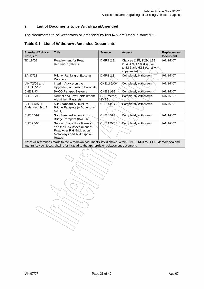
9. List of Documents to be Withdrawn/Amended The documents to be withdrawn or amended by this IAN are listed in table 9.1. Table 9.1 List of Withdrawn/Amended Documents Standard/Advice Note, etc
Title Source Aspect Replacement Document
TD 19/06 Requirement for Road Restraint Systems
DMRB 2.2 Clauses 1.25, 1.29, 1.39, 2.34, 4.9, 4.10, 4.46, 4.55 to 4.62 and 4.68 partially superseded
IAN 97/07
BA 37/92 Priority Ranking of Existing Parapets
DMRB 2.3 Completely withdrawn IAN 97/07
IAN 72/06 and CHE 165/06
Interim Advice on the Upgrading of Existing Parapets
CHE 165/06 Completely withdrawn IAN 97/07
CHE 1/93 BACO Parapet Systems CHE 11/93 Completely withdrawn IAN 97/07 CHE 30/96 Normal and Low Containment
Aluminium Parapets CHE Memo 30/96
Completely withdrawn IAN 97/07
CHE 44/97 + Addendum No. 1
Sub Standard Aluminium Bridge Parapets (+ Addendum No. 1)
CHE 44/97 Completely withdrawn IAN 97/07
CHE 45/97 Sub Standard Aluminium Bridge Parapets (BACO)
CHE 45/97 Completely withdrawn IAN 97/07
CHE 25/03 Second Stage Risk Ranking and the Risk Assessment of Road over Rail Bridges on Motorways and All-Purpose Roads
CHE 125/03 Completely withdrawn IAN 97/07
Note: All references made to the withdrawn documents listed above, within DMRB, MCHW, CHE Memoranda and Interim Advice Notes, shall refer instead to the appropriate replacement document.

Interim Advice Note 97/07 Assessment and Upgrading of Existing Vehicle Parapets
IAN 97/07 Page 22 of 49 Aug 07
10. Contacts If you have any questions on the use of this document please contact:
Rick Janowski: �STD 0161 930 5805 � email: [email protected] Daniel Ruth: �STD 0121 678 5980 � email: [email protected]
Interim Advice Note 97/07 Assessment and Upgrading of Existing Vehicle Parapets
IAN 97/07 Page 23 of 49 Aug 07
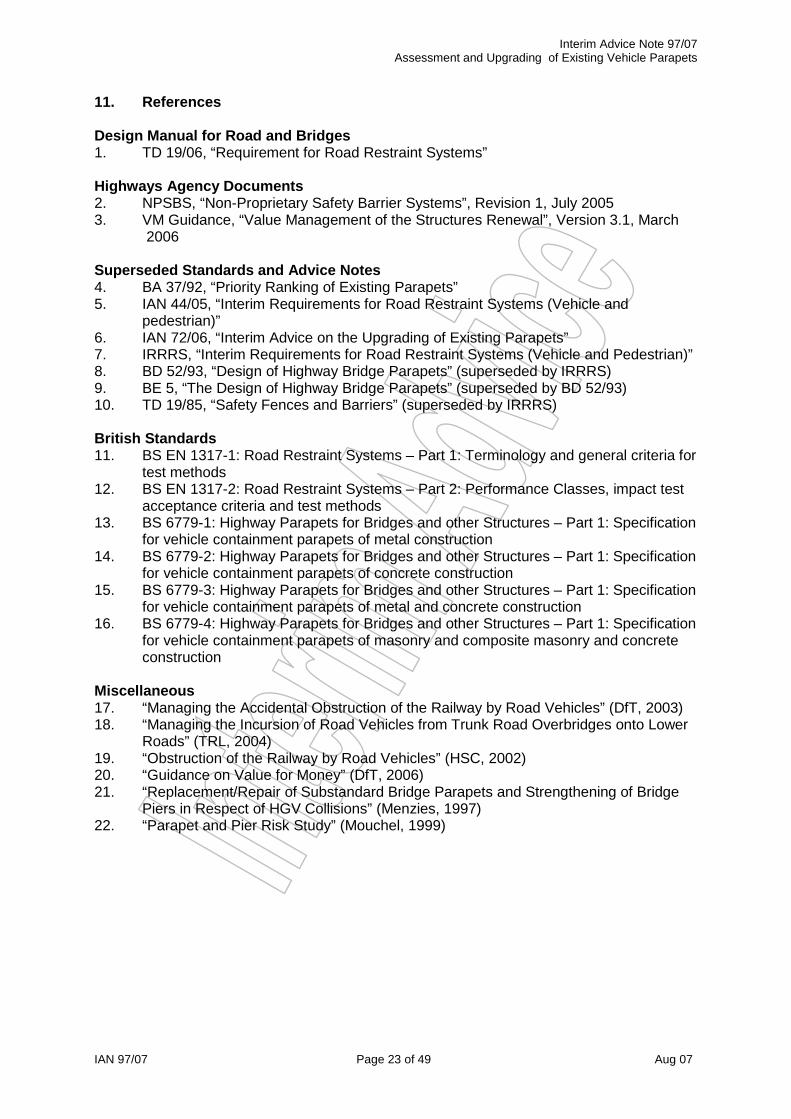
11. References Design Manual for Road and Bridges 1. TD 19/06, “Requirement for Road Restraint Systems” Highways Agency Documents 2. NPSBS, “Non-Proprietary Safety Barrier Systems”, Revision 1, July 2005 3. VM Guidance, “Value Management of the Structures Renewal”, Version 3.1, March
2006 Superseded Standards and Advice Notes 4. BA 37/92, “Priority Ranking of Existing Parapets” 5. IAN 44/05, “Interim Requirements for Road Restraint Systems (Vehicle and
pedestrian)” 6. IAN 72/06, “Interim Advice on the Upgrading of Existing Parapets” 7. IRRRS, “Interim Requirements for Road Restraint Systems (Vehicle and Pedestrian)” 8. BD 52/93, “Design of Highway Bridge Parapets” (superseded by IRRRS) 9. BE 5, “The Design of Highway Bridge Parapets” (superseded by BD 52/93) 10. TD 19/85, “Safety Fences and Barriers” (superseded by IRRRS) British Standards 11. BS EN 1317-1: Road Restraint Systems – Part 1: Terminology and general criteria for
test methods 12. BS EN 1317-2: Road Restraint Systems – Part 2: Performance Classes, impact test
acceptance criteria and test methods 13. BS 6779-1: Highway Parapets for Bridges and other Structures – Part 1: Specification
for vehicle containment parapets of metal construction 14. BS 6779-2: Highway Parapets for Bridges and other Structures – Part 1: Specification
for vehicle containment parapets of concrete construction 15. BS 6779-3: Highway Parapets for Bridges and other Structures – Part 1: Specification
for vehicle containment parapets of metal and concrete construction 16. BS 6779-4: Highway Parapets for Bridges and other Structures – Part 1: Specification
for vehicle containment parapets of masonry and composite masonry and concrete construction
Miscellaneous 17. “Managing the Accidental Obstruction of the Railway by Road Vehicles” (DfT, 2003) 18. “Managing the Incursion of Road Vehicles from Trunk Road Overbridges onto Lower
Roads” (TRL, 2004) 19. “Obstruction of the Railway by Road Vehicles” (HSC, 2002) 20. “Guidance on Value for Money” (DfT, 2006) 21. “Replacement/Repair of Substandard Bridge Parapets and Strengthening of Bridge
Piers in Respect of HGV Collisions” (Menzies, 1997) 22. “Parapet and Pier Risk Study” (Mouchel, 1999)

Appendix A Interim Advice Note 97/07 Assessment and Upgrading of Existing Vehicle Parapets
IAN 97/07 Page 24 of 49 Aug 07
Appendix A: ALARP Based Risk Ranking Tools A1 General ALARP based risk assessment tools are provided for the following three situations:
� Assessment of substandard parapets. (Ref. section A1) � Assessment of substandard parapet connections. (Ref. section A2) � Assessment of substandard protective safety barriers. (Ref. section A3)
For all of these situations, the ALARP based Risk Ranking Score, RALARP, is expressed by the following relationship:
AADT • F1 • F2 •·F3RALARP = 10000
… (Equation A1)
Where AADT is the average two-way daily traffic flow on the road adjacent to the parapet (or twice the AADT on one-way traffic roads), and the three factors, F1 to F3, are defined in sections A2, A3 and A4, for substandard parapets, protective safety barriers and parapet connections respectively. The value of AADT should be obtained from existing data where available. (e.g., HA's TRADS system at www.trads2.co.uk and DfT's AADT site at http://www.dft-matrix.net/)Where data is not available, the value of AADT should be estimated, using local knowledge of the maintaining agent, and the local highway authority if appropriate. Table A.1 provides typical AADT values for different types of roads which may be used as a basis for estimating. Table A1 Typical AADT Values
Road Type Typical Range of Two-Way AADT Green Lane or Farm Access Road Less than 200 Unclassified Road 200 to 2000 Class B or C Road 2000 to 7000 Single Carriageway Class A or Trunk Road 7000 to 20000 Dual Carriageway Class A or Trunk Road 15000 to 40000 Motorway Greater than 35000
A2 ALARP Assessment of Substandard Parapets For the assessment of substandard parapets, the three factors, F1 to F3, are defined as follows:
F1 = Parapet containment factor (Ref. clause A2.1) F2 = Site features factor (Ref. clause A2.2) F3 = Ease of upgrading factor (Ref. clause A2.3)
Upgrading is justified, as part of major maintenance, when,
RALARP > 1.0

Appendix A Interim Advice Note 97/07 Assessment and Upgrading of Existing Vehicle Parapets
IAN 97/07 Page 25 of 49 Aug 07
A2.1 Values for the parapet containment factor, F1, should be derived from tables A2.1 (a) and A2.1 (b). Table A2.1 (a) Required Containment Capacity, CREQ (as Proportion of N2)
Speed limit (mph) Bridge/Structure over or adjacent to: 70 60 50 40 302
Railway 1.00•N2 at all speed limits Road or Other1 1.00•N2 0.73•N2 0.50•N2 0.33•N2 0.20•N2 Notes: (1) Other refers to river, canal, NMU/agricultural access routes, open land, etc.
(2) A speed limit of 30mph should be assumed for accommodation bridges. (3) Speed limits on roundabouts should not be assumed to exceed 40mph.
Table A2.1 (b) Parapet Containment Factor, F1
Remnant Capacity, RCONT (as % of Required Containment Capacity, CREQ)0% — 33% 34% — 66% 67% — 100%
5.00 1.00 Upgrading not required Note: The remnant capacity should generally be assessed on the basis of engineering judgement. (Ref. Section 6)
A2.2 Values for the site features factor, F2, should be derived from table A2.2. Although this factor is mostly dependent on clearance, allowances should also be made for proximity to junctions and poor accident record. Table A2.2 Site Features Factor, F2
Clearance to Parapet from the Edge of the Nearest Permanent Running Lane (m) 0.0 1.0 2.0 3.0 4.0 5.0 6.0
1.50 1.50 1.25 1.00 0.75 0.50 0.50 Notes: (1) Intermediate values should be derived by linear interpolation.
(2) If within the standard sight stopping distance of a junction/interchange/sharp bend add 0.25 to the value for F2.
(3) If at a location with a poor accident record add 0.50 to the value of F2.
A2.3 Values for the ease of upgrading factor, F3, should be derived from table A2.3. Table A2.3 Ease of Upgrading Factor, F3
Method of Upgrading Use existing Anchors New Drilled Anchors Modify Supporting Member
1.00 0.75 0.50 Note: Upgrading should be undertaken as part of major maintenance works. The above values reflect this assumption. Significantly lower values would apply otherwise.

Appendix A Interim Advice Note 97/07 Assessment and Upgrading of Existing Vehicle Parapets
IAN 97/07 Page 26 of 49 Aug 07
A3 ALARP Assessment of Substandard Parapet Connections For the assessment of substandard parapets, the three factors, F1 to F3, are defined as follows:
F1 = Connection factor (Ref. clause A3.1) F2 = Site features factor (Ref. clause A2.2 as for substandard parapets)) F3 = Ease of upgrading factor (Ref. clause A3.2)
Upgrading is justified, as part of major maintenance, when,
RALARP > 2.0 A3.1 Values for the connection factor, F1, should be derived from tables A3.1 (a) and A3.1 (b). Table A3.1 (a) Required Ultimate Tensile Resistance of Connection
Speed limit (mph) 70 60 50
330kN 240kN 165kN Notes: (1) Upgrading is not required where the speed limit is less than 50mph.
(2) A speed limit of 30mph should be assumed for accommodation bridges. (3) Speed limits on roundabouts should be assumed not to exceed 40mph.
Table A3.1 (b) Connection Factor, F1
Remnant Capacity, (as % of Required Connection Resistance) 0% — 33% 34% — 66% 67% — 100%
3.00 1.00 Upgrading not required Note: The remnant capacity should be assessed on the basis of engineering judgement.
A3.2 Values for the ease of upgrading factor, F3, should be derived from table A3.2. Table A3.3 Ease of Upgrading Factor, F3
Method of Upgrading Provide connection without upgrading safety barrier or modifying parapets
Upgrading of safety barrier ormodifications to parapets required.
Upgrading of safety barrier and modifications to parapets required.
1.00 0.75 0.50 Note: Upgrading should be undertaken as part of major maintenance works. The above values reflect this assumption. Significantly lower values would apply otherwise.

Appendix A Interim Advice Note 97/07 Assessment and Upgrading of Existing Vehicle Parapets
IAN 97/07 Page 27 of 49 Aug 07
A4 ALARP Assessment of Substandard Protective Safety Barriers For the assessment of substandard parapets, the three factors, F1 to F3, are defined as follows:
F1 = Overall containment factor (Ref. clause A4.1) F2 = Site Features factor (Ref. clause A2.2 as for substandard parapets)) F3 = Working width factor (Ref. clause A4.2)
Upgrading is justified, as part of major maintenance, when,
RALARP > 2.0 A4.1 Values for the overall containment factor, F1, should be derived from clause A2.1 by considering the combined remnant capacity of parapet and protective safety barrier (i.e., by adding the respective remnant capacities). However, if the combined remnant capacity is above 66%, F1 should be taken as 1.0. A4.2 Values for the working width factor, F3, should be derived from tables A4.1 (a) and A4.1 (b).
Table A4.1 (a) Required Working Width (Proportion of Full Working Width)
Speed limit (mph) 70 60 50
1.00•WW 0.73•WW 0.50•WW Notes: (1) Upgrading is not required where the speed limit is less than 50mph.
(2) A speed limit of 30mph should be assumed for accommodation bridges. (3) Speed limits on roundabouts should be assumed not to exceed 40mph.
Table A4.2 (b) Working Width Factor, F3
Working Width Provided (as % of Required Working Width) 0% — 33% 34% — 66% 67% — 100%
3.00 1.00 Upgrading not required

Appendix B Interim Advice Note 97/07 Assessment and Upgrading of Existing Vehicle Parapets
IAN 97/07 Page 28 of 49 Aug 07
Appendix B: Incursion Risk Ranking Tools B1 Background The guidance contained within this appendix combines incursion risk ranking tools from the following sources to avoid unnecessary duplication and to simplify the assessment process:
� DfT Report “Managing the accidental obstruction of the railway by road vehicle” (DfT, 2003)
� TRL Unpublished Report “Managing the incursion of road vehicles from trunk road overbridges onto lower roads” (TRL, 2004)
The guidance combines the tools from these sources to avoid unnecessary duplication, whilst updating to be consistent with TD 19/06, “Requirement for Road Restraint Systems”. Road-Rail and Road-Road incursion risk ranking tables are provided in section B7, for both single carriageway and motorway/dual carriageway road over situations. Guidance on the relevant factors is provided in sections B3 to B6 as follows:
� Section B3 f1 to f11 Road over factors (single carriageway) � Section B4 f1 to f11 Road over factors (motorway/dual carriageway) � Section B5 f12 to f14 Rail under factors � Section B6 f12 to f14 Road under factors
B2 Instructions: Overall scoring and methodology You get the overall score for a bridge by adding all 14 factors together.
As a guide, an increase of two in a score for any of the factors or for an overall risk score implies a doubling of the risk, so 6 is twice as bad as 4, and 12 is eight times worse than 6. This gives a wide range of risk values. A score of 90 implies that the risk is approximately a million times bigger than a score of 50. The scoring regime assumes that no factor needs a score of zero, as even the best protection still allows a slim chance of a vehicle or debris, reaching the line. Assessors should rank bridges according to score. They should assess the highest scoring bridges in more detail to see how they can be improved. As a guide, scores of 100 or more are significant and scores of 70 or more would suggest that highway authorities should at least consider the practicability of improvements. This does not rule out simple and cost effective improvements at bridges that score less than 70. Mitigation action act is not strictly required when:
� For bridges carrying single carriageway roads that either score one for factor 1 (road approach containment) or score of 1 for factor 5 (site topography).
� For bridges carrying motorway and dual carriageway roads that score one for factor 1 (road approach containment) combined with a score of 1 for factor 5 (site topography) and a score of two or less for factor 8 (vehicle parapet resilience).

Appendix B Interim Advice Note 97/07 Assessment and Upgrading of Existing Vehicle Parapets
IAN 97/07 Page 29 of 49 Aug 07
B3 Factors: Single Carriageway Road over Rail or Road
f1: Road approach containment on upper road The factor is used to consider the possibility of a road traffic accident (RTA) resulting in a vehicle or debris continuing along the road approach side slope and then onto the railway track or road below. It is also used to consider a vehicle or debris gaining access either side of the parapets in a cutting. Where containment varies on each approach side slope, (that is, at each of the four corners), assessors must consider the worst case. In particular, they should consider containment immediately adjacent to parapet ends and score the factor accordingly. For example, good containment on a road approach up to 3m from the parapet, but with no protection in the 3m section, would be marked 24.
Score 1 for acceptable containment (safety fence, heavily wooded road approach slopes, buildings or brickwork walls 450 or thicker).
The scorer should assess whether a fence takes account of normal design parameters. For instance, a safety fence is not designed to resist perpendicular loading at a Z bend over a railway bridge. “Heavily wooded” means trees of more than 500mm girth at spacing of less than 2m. Buildings on approaches or brickwork/masonry walls in good condition, 450mm or greater in thickness, to be scored as 1. Where the road speed is not greater than 30mph, the scorer may include Trief safety kerb in this category. Virtually zero chance of a road vehicle penetrating the containment, or evading the end of it.
Score 12 for inadequate containment (inadequate safety fence, lightly wooded road approach slopes or brickwork minimum 225 thick)
At this score, the safety fence is being expected to provide containment perpendicular to its face, or it meets a standard now superseded, or it is a non-standard type. Trees are of less than 500 mm girth and/or spacing of 2m or more. Brick/masonry walls in good condition are a minimum of 225mm thick. Some sites have several layers of protection, each of which would be inadequate on its own, but which together offer a reasonable level of containment. For example, a pedestrian safety barrier at the kerb edge combines with a close-boarded fence on concrete posts at the boundary. Perceived chance of vehicle evading or penetrating a fence or trees.
Score 24 for non-existent containment (including post rail/wire fencing) At this score, road approach slopes have no fencing or only post/wire or post/rail fencing. There is no significant vegetation (trees or bushes less than 250 mm girth and/or at centres greater than 2m).

Appendix B Interim Advice Note 97/07 Assessment and Upgrading of Existing Vehicle Parapets
IAN 97/07 Page 30 of 49 Aug 07
High chance of a vehicle that leaves the highway continuing at undiminished speed.
f2: Upper road alignment (horizontal) Road width and horizontal alignment are important, as a wide straight road with passing clearance for two oncoming vehicles is an obviously lower risk than a narrow road where one vehicle has to give way. The curved approaches increase the chance of an accident due to reduced sighting distance and reaction time. “Road width” is the width taken as the width of road surface, disregarding any footpath or verge.
f3: Upper road alignment (vertical) Blind summits reduce the sighting and reaction distance for two oncoming vehicles meeting at a bridge with restricted clearance. Assessors should determine visibility on straight road hump backs in accordance with the Design Manual for Road & Bridges, TD 9/93.
f4: Actual speed of approaching road traffic on upper road The faster approaching road traffic is going, the greater the risk of an accident. Speed also contributes to the effect of the incident. The faster a vehicle is travelling, the further it (and any debris) may travel afterwards. Assessors should use actual speed figures, measured on site. Where these are not available, they should evaluate speeds during the site visit. Assessors should disregard signed and designed speeds. Experience indicates that actual speeds may be much higher.
f5: Site topography This factor involves subjectively assessing the likelihood of a vehicle, or substantial parts of it, or its load, reaching the railway track or road below following a RTA which breaches any containment in factor 1. The assessor should consider how far an errant vehicle leaving a high-speed road would travel. This may be affected by the:
� gradient of the side slope; � distance from toe of cutting slope to the nearest point on the railway track or road
below; � height of the railway track bed or road below in relation to the field level next to the
approach slopes; � proximity of railway track or road below to ends of the vehicle parapets; � increased risk of incursion due to skew effects at obtuse corners; � height of the deck above railway track or road below; � likelihood of the vehicle becoming airborne; � skid resistance of the ground between the upper road, and the railway track or road
below; and � presence of shrubbery between the carriageway upper road, and the railway track or
road below.

Appendix B Interim Advice Note 97/07 Assessment and Upgrading of Existing Vehicle Parapets
IAN 97/07 Page 31 of 49 Aug 07
This factor is not intended to include any assessment of the risk associated with parts of the vehicle parapet or safety fence being displaced onto the rail track or road below. We consider this in factor 8.
f6: Site specific hazards increasing the likelihood of a RTA on upper road Because it is not practicable to have a simple risk ranking which considers all possible hazards, we decided to include a factor so that the assessor can take account of additional hazards that may increase the risk of a RTA. These include (but are not limited to):
� farm access/field gates; � road junctions; � private driveways; � schools, hospitals, etc; � factory entrances; � steep descent on upper road approach and adjacent access tracks; � lay-bys; � bus stops; � car parking; and � cafes and shops.
All of these may lead to conflicting or unusual traffics movements.
Score 1 for no obvious hazard Score 5 for a single minor hazard, such as a field gate, lay-by or bus stop Score 9 for multiple minor hazards or a single major hazard, such as a school, hospital or factory entrance, leading to conflicting traffic movements.
Assessors should consider upper road traffic speeds, and the distance of hazards from parts of bridge approaches susceptible to road vehicle incursion. A frequently used field gate 10m from a relatively unprotected wall on a narrow high speed road would score higher than one 100m away on a lightly used, wider road.
f7: Site specific hazards increasing the consequences of the event (between the upper road and railway track or road below)
Again, due to the difficulty of including all possible hazards, we have included a factor so that the assessor can take account of them. These include, but are not limited to; exposed gas or chemical pipelines, water mains, communication cabinets, etc, that are:
� attached to the bridge structure; � adjacent to the bridge approaches; or � parallel with the railway tracks or road below.
Risk increases where there is more than one pipeline or hazard. Some railway infrastructure is likely to worsen the effects of an accident. Some, such as switch and crossing work or junctions, are a derailment hazard. Others are likely to increase the severity of an accident if hit by a derailed vehicle. These include station platforms, bridge piers and abutments and tunnel portals within 800m (half a mile) of the bridge site. Disregard overhead line masts within this factor.

Appendix B Interim Advice Note 97/07 Assessment and Upgrading of Existing Vehicle Parapets
IAN 97/07 Page 32 of 49 Aug 07
Road infrastructure likely to increase severity of incident to include bridge piers and abutments and tunnel portals etc within 800m (1/2 mile) of structure.
Score 1 for no obvious hazard Score 3 for a single hazard, such as a gas main, oxygen pipe and so on. Score 5 for multiple hazards and/or railway or highway infrastructure likely to increase the severity of an accident
f8: Vehicle parapet resilience on upper road Parapet resilience (containment) is important because the effect of an accident will be less if the parapet can keep crashed vehicles on the bridge deck. On multi-track railway routes a parapet may limit the effects of any RTA to outer tracks. Modern welded steel half through bridge decks offer containment to at least H4a standard. Earlier riveted steel/wrought iron half through decks score higher, due to the possibility of rivet or deck corrosion. Where the parapet is in poor condition due to age, corrosion or existing accident damage, assessors should raise the score to at least the next category.
Score 1 for H4a parapet, or welded steel half through bridge deck. Score 2 for N2 parapet, or riveted steel/wrought iron half through bridge deck. Score 5 for 450 thick brickwork parapet. Score 7 for 340 thick brickwork parapet. Score 11 for cast iron or corrugated sheet parapet.
f9: Upper road verges & footpaths Road approaches and bridge decks with wide footpaths or verges reduce the risk of RTAs, as they give drivers extra width to take avoiding action and offer the psychological comfort of a wider gap to steer through. At sites where pedestrian safety barriers have been provided, the factor should be marked on the distance between barrier and kerb edge.
f10: Upper road signage and markings Adequate road signage and markings help to warn strangers to an area that a hazard exists. But their effects are limited and the consensus view is that regular road users may ignore signage and markings. This makes locals more likely to crash. For this reason signage is generally considered to be of lower importance in the ranking procedure.
Score 1 for signage/markings considered fit for purpose and which are clean and clearly visible, or are not considered to be needed at the location. Score 4 for non-existent, inadequate, or obscured signage/markings, at a location where they are considered necessary.
Note: Assessors should notify the highway authority of a score of 4 for early action, regardless of the perceived risk at the location based on the total score from all factors.

Appendix B Interim Advice Note 97/07 Assessment and Upgrading of Existing Vehicle Parapets
IAN 97/07 Page 33 of 49 Aug 07
f11: Volume of road traffic on upper road Road traffic volume increases the probability of a RTA. This model was developed using the number of HGVs per day, but assessors may apply any measure of recorded traffic flow, subject to similar weighting. HGVs and farm traffic are more likely to be involved in an accident on narrow roads, as they reduce the passing space for oncoming traffic. This factor may need upwards adjustment to the next higher category where local conditions such as the presence of a quarry increase traffic, but may not be reflected in the original survey figures. Equivalent traffic flows for all vehicle types may be substituted, depending upon the units of measurement used by the relevant highway authority. Assessors may use the following vehicles per day figures where the highway authority cannot provide traffic volumes in HGVs.
Score 1 for 0 to10 HGVs per day (<200 vehicles per day)Score 2 for 11 to 100 HGVs per day (<2000 vehicle per day) Score 3 for 101 to 500 HGVs per day (<7150 vehicle per day) Score 4 for 501 to 1000 HGVs per day (<12500 vehicle per day) Score 5 for over 1000 HGVs per day (>12500 vehicle per day)
The highway authority will provide traffic figures.

Appendix B Interim Advice Note 97/07 Assessment and Upgrading of Existing Vehicle Parapets
IAN 97/07 Page 34 of 49 Aug 07
B4 Factors: Motorway or Dual Carriageway Road over Rail or Road
f1: Upper road approach containment This factor is used to consider the possibility of a road traffic accident (RTA) resulting in a vehicle or debris continuing along the road approach side slope and then onto the railway track or road below. It is also used to consider a vehicle or debris gaining access either side of the safety barriers and transitions prior to the vehicle parapet in a cutting. This factor is to be considered in conjunction with f5 (Site topography) to determine the "length of need". Where containment varies on each approach, (that is, at each corner of the bridge) assessors must consider the worst case.
Score 1 for very high containment This means that there is very high containment barrier (H4a) of adequate length with appropriate transition to normal containment safety barrier (N2), in accordance with TD 19/06. These should either be continuous or used in conjunction with a very high containment level vehicle parapet. See factor 8. Assessors should particularly consider the “length of need” for high containment safety barriers and/or vehicle parapets on high-speed roads. The “length of need” is the length reasonably required to prevent a vehicle from reaching the railway or lower road. Road engineers are likely to meet “the length of need” either by using a very high containment level parapet and transition or continuous high containment barriers. Assessors should only include sites in this category where the length of high containment protection is reasonably likely to prevent most vehicles reaching the road below from either a wide approach angle (e.g. hitting the containment at an angle of more than 20 degrees) or a shallow approach angle (leaving the road before the containment begins and continuing behind the barrier towards the hazard).
Score 6 for normal containment This score covers sites with normal containment safety barriers of adequate length, fully complying with TD 19/06, and connected to a normal containment level parapet in accordance with the requirements for non-proprietary and proprietary safety barriers.
Score 12 for approach safety barriers of normal containment that are sub-standard, defective, damaged or too short
These sites have safety barriers that do not comply with current standards. This is either as a result of poor original installation, deterioration, damage, settlement or any other significant defect, or because they are too short.
Score 24 for no effective vehicle restraint system or very low containment, non-standard walls, fences or barriers
Here there is a high probability of an errant vehicle continuing at the same speed and/or angle.

Appendix B Interim Advice Note 97/07 Assessment and Upgrading of Existing Vehicle Parapets
IAN 97/07 Page 35 of 49 Aug 07
f2: Upper road alignment (horizontal and vertical) Road width and horizontal and vertical alignments are important, but are unlikely to be a significant feature of high-speed major roads. Length of sight lines are important, as blind summits and bends can reduce sighting and reaction times. Assessors should determine inter-visibility on straight road humpbacks and bends in accordance with the ‘Design Manual for Roads and Bridges’, TD 9/93. Assessors should consider using the single carriageways ranking tool for major roads with speed restrictions or with narrow widths and poor alignments.
f3: Sleep-related vehicle accidents (SRVAs) on upper road Recent research has identified a number of RTAs caused by drivers falling asleep. These are known as sleep-related vehicle accidents or SRVAs. The study found that SRVAs are relatively common on high-speed major roads. Proportions ranged from 16 percent to 30 percent of all reported fatal, injury and damage only accidents. In a recent study of SRVAs, the highest proportion was found on a featureless, unlit stretch of the M40 in rural Warwickshire. The research indicated that SRVAs are independent of traffic density, but there are some identifiable characteristics that lead to clusters of these accidents. Availability of service areas did not seem to affect SRVAs. But the study found clusters of SRVAs on slow right hand bends and towards the end of a long route. For example, run-off accidents were found clustered on the eastbound carriageway of the eastern end of the M180 and B180, but there was no such cluster on the westbound carriageway. SRVAs were also found to occur on slow left hand bends. Most major roads have a central reservation safety fence, which heavy goods vehicles (HGVs) may broach thereby posing a particular risk of incursion on to railway lines. (See 2.2.11: Traffic Volume).
f4: Actual speed of approaching road traffic on upper road This ranking tool is intended for use on fast roads where higher traffic speeds increase both the likelihood and the effect of an accident. This is due to the distance over which the vehicle and debris may travel after the accident, and/or the capability of the vehicle restraint system. If possible, assessors should use actual speeds taken from site measurements. If these are not available, they should estimate the speed at medium traffic density and note it on the scoring sheet. Assessors should consider traffic density when measuring traffic speed, as these two factors can be interdependent, producing an unreliable figure may result.
f5: Site topography This factor involves subjectively assessing the likelihood of a vehicle, or substantial parts of it, or its load, reaching the railway track or road below following a RTA which breaches any containment in factor 1. The assessor should consider how far an errant vehicle leaving a high-speed road would travel. This may be affected by the:

Appendix B Interim Advice Note 97/07 Assessment and Upgrading of Existing Vehicle Parapets
IAN 97/07 Page 36 of 49 Aug 07
� gradient of the side slope; � distance from toe of cutting slope to the nearest point on the railway track or road
below; � height of the railway track bed or road below in relation to the field level next to the
approach slopes; � proximity of railway track or road below to ends of the vehicle parapets; � increased risk of incursion due to skew effects at obtuse corners; � height of the deck above railway track or road below; � likelihood of the vehicle becoming airborne; � skid resistance of the ground between the upper road, and the railway track or road
below; and � presence of shrubbery between the carriageway upper road, and the railway track or
road below. This factor is not intended to include any assessment of the risk associated with parts of the vehicle parapet or safety fence being displaced onto the rail track or road below. We consider this in factor 8. f6: Site specific hazards increasing the likelihood of a RTA on upper road Analysis of accident data suggests that RTAs on major, high-speed roads are clustered near junctions or other areas, which can lead to conflicting or unusual traffic movements or vehicles changing lanes. The following are all likely to increase the frequency of RTAs:
� interchanges; � road junctions; � lane drops; � emergency service vehicle recesses; � no hard shoulders � service areas; and � lay-bys.
Assessors should generally consider the distance of a hazard from the bridge approach when scoring this factor. Raise the score by one band for sites prone to long periods of bad weather, such as exposed moorland. Consideration should be given to increasing the score by two if there is no adequate carriageway lighting. f7: Site specific hazards increasing the consequences of the event (between the
upper road and railway track or road below) These include, but are not limited to, exposed pipelines, water mains, communication cabinets etc, that are:
� attached to the bridge structure; or � adjacent to the bridge approaches; or � parallel with the railway tracks or road below.
Risk increases where there is more than one pipeline or hazard. Some railway infrastructure is likely to worsen the consequence of an accident. Some, such as switch and crossing work or junctions, are a derailment hazard. Others are likely to increase the severity of an incident if hit by a derailed vehicle. These include station platforms, bridge piers and abutments and tunnel portals within 800m (1/2 mile) of the bridge site. Disregard overhead line masts within this factor.

Appendix B Interim Advice Note 97/07 Assessment and Upgrading of Existing Vehicle Parapets
IAN 97/07 Page 37 of 49 Aug 07
Road infrastructure likely to increase severity of incident to include bridge piers and abutments and tunnel portals etc within 800m (1/2 mile) of structure.
f8: Vehicle parapet resilience on upper road Parapet resilience (containment) is important because the effect of an accident will be less if the parapet can contain and redirect crashed vehicles on the bridge deck. On multi-track railway routes a parapet may limit the effects of any RTA to the outer tracks. Refer to TD 19/06 for details of parapet types. The type of parapet will also, by definition, specify the height and the infill. This will, in turn, determine the likelihood of debris from the bridge fouling the railway track or road below.
f9: Hard shoulders, edge strips, road verges and footpaths on upper road Road approaches and bridge decks with hard shoulders, edge strips and/or wide footpaths or verges reduce the risk of RTAs, as they give drivers extra width to take avoiding action and to regain control of an their vehicles.
f10: Quality and effectiveness of edge markings and raised rib markings on upper road Edge markings, raised rib markings (sometimes called “rumble strips”) and reflective road studs (sometimes called “cats eyes”) on the nearside edge of a major road alert drivers to their position. They should help to reduce the risk of vehicles leaving the nearside of major roads. There is some evidence that adequate, well-maintained raised rib markings can be particularly effective in overcoming run-off accidents where fatigue is a factor. However, assessors need to check their condition. Note: Assessors should notify the highway authority of a score of 4 for early action, regardless of the perceived risk at the location based on the total score from all factors.
f11: Combined volume of road traffic on both carriageways of upper road Heavy road traffic has been shown to increase the likelihood of a RTA. We measure traffic flow for major high-speed roads with high volumes of traffic in vehicles per day (vpd). On average HGVs make up about 10 percent of the traffic on motorways and all-purpose trunk roads and are involved in about 7 per cent of RTAs. However, the mix of traffic may add to the risk of vehicle incursion, particularly in relation to containment (see f1: upper road approach containment). Assessors should increase the score by one band if HGVs form 12 percent or more of total traffic.

Appendix B Interim Advice Note 97/07 Assessment and Upgrading of Existing Vehicle Parapets
IAN 97/07 Page 38 of 49 Aug 07
B5 Factors: Rail under Road
f12: Permissible line speed and track alignment We consider this to be important because derailments are more likely on high-speed routes. We have included the curve factor due to the increased chance of derailment on curves, and the reduced braking distance if the curve obscures the vehicle and/or debris on the track from the train driver’s view. Scoring reflects the increased chance of derailment with increased speed, or track curvature, and also that the consequences of the event can increase with speed. For bridges carrying single carriageway roads, on routes with more than two tracks and where the vehicle parapet resilience in factor 8 scores 2 or less, it is considered that, unless other circumstances indicate otherwise, assessors should only consider the speed of the outer lines. The assumption is that the parapets would contain any crashed vehicle and only the outer tracks would be affected. The operating speed categories allow assessors to use the model for the Channel Tunnel Rail Link and other high-speed routes, and where speed enhancement schemes are being considered. Details of line speeds are available from the railway infrastructure authority. This may be for example Network Rail, London Underground Ltd, NEXUS (Tyne & Wear PTE), a preserved railway operator or other infrastructure authority. The site inspection will establish the existence of curvature.
f13: Type of rail traffic The type of rail traffic can affect the severity of a railway incident following a RTA in a number of ways. The five categories used are a development of work to assess the risk from signals passed at danger (SPADS). This includes the likelihood of derailment and the crash resistance of different rolling stock types. Though a route may be considered to be used primarily by one of the lower risk categories below, if more than five higher risk trains use the route each day, assessors should include it in the higher scoring group. For example, the East Coast Mainline north of York, is principally a loco hauled passenger route for high speed trains and IC225s, but it also carries sliding door Sprinters and some dangerous goods traffic, so it scores 5. For bridges carrying single carriageway roads, if f8 (vehicle parapet resilience) scores 2 or less, score f13 on the basis of outermost tracks of a multi-track railway
Score 1 for freight only routes, not carrying dangerous goods such as petrol. These are considered the least risk, as generally there is a reduced chance of derailment. Also substantially fewer casualties are possible. Score 3 for loco hauled passenger trains, to include push-pull services such as high speed trains and IC225s and similar. These have a reduced risk of derailment, as they are loco hauled and have better crash resistance than lighter rolling stock. The possible number of injuries, however, increases the risk.

Appendix B Interim Advice Note 97/07 Assessment and Upgrading of Existing Vehicle Parapets
IAN 97/07 Page 39 of 49 Aug 07
Score 5 for sliding door multiple units (max speed 100mph), and/or dangerous goods freight trains. Modern diesel and electric sliding door multiple units (Sprinters, EMU’s) and trains carrying dangerous goods increase risk. This is due to the high number possible casualties following any explosion or fire. Score 7 for slam door multiple units and sliding door multiple units (maximum speed greater than 100mph). This is because older slam door trains have less structural integrity than modern ones and passengers in the leading vehicles of modern higher speed multiple units are at greater risk of death or injury. Score 11 for light rail. Lightweight passenger trains, as operated by NEXUS (Tyne & Wear Metro) are at greatest risk. This is due to the high number of possible casualties and the increased chance of derailment of a light train, when compared with a conventional multiple unit or loco hauled service.
Light rail does not include preserved railways operating under a Light Railway Order. You should assess these against the types of vehicle they normally operate. The railway infrastructure controller will confirm the types of traffic likely to use a route.
f14: Volume of rail traffic The more trains use a route, then obviously the greater the chance of one being involved in the aftermath of a RTA. The railway infrastructure authority will provide usage figures for a particular route. Network Rail will provide figures from its NETRAFF system. NETRAFF will give information for each track at a location, split into passenger/freight movements. Assessors should first score the total for the location, even at multi-track locations.
Network Rail will provide figures from its NETRAFF system. NETRAFF will give information for each track at a location, split into passenger/freight movements. Assessors should first score the total for the location. This also applies to bridges over single carriageway roads at multi-track sites, where the assessor is only looking at the outer tracks in factor 12, due to acceptable parapet containment in factor 8. The information by track, split into passenger/freight movements, may be useful later, when carrying out a more detailed risk assessment

Appendix B Interim Advice Note 97/07 Assessment and Upgrading of Existing Vehicle Parapets
IAN 97/07 Page 40 of 49 Aug 07
B6 Factors: Road under Road
f12: Actual speed of traffic on lower road The higher the traffic speeds on the lower roads the greater the likelihood and consequences of an accident. The fastest lower road drivers will have less time to react to, and avoid, a hazard ahead. In addition, the faster the vehicle is travelling at impact, the greater the kinetic energy on impact. If possible, assessors should use actual speeds taken from site measurements. If these are not available, they should estimate the mean speed of all traffic at medium traffic density and note it on the scoring sheet. Assessors should consider traffic density when measuring traffic speed, as these two factors can be interdependent, producing an unreliable figure.
f13: Site specific hazards increasing consequences of event on lower road Assessors should consider anything within a 100m zone of influence (100m beyond each end of the bridge parapet) that may pose additional hazards. These include, but are not limited to, the presence of:
� pedestrians, especially if stationary (e.g. at bus stops or crossing); � narrow road width and/or verge width (inability to avoid a vehicle blocking the road); � poor or no lighting, particularly with low bridges; � reduced sight lines (e.g. bends, vegetation); � adjacent land use (e.g. housing, schools); and � queuing traffic (traffic signals, junctions).
Score 1 for sites with no site specific hazards on the lower road. For sites with site specific hazards, a doubling of risk is assumed for 2-way roads because of the increased likelihood of more vehicles and casualties being involved. Score 3 for a 1-way lower road (or 5 for a 2-way lower road) with a single site specific hazard. Score 5 for a 1-way lower road (or 7 for a 2-way lower road) with two site specific hazards. Score 7 for a 1-way lower road (or 9 for a 2-way lower road) with queuing or with 3 or more site specific hazards. These should include sites which commonly have pedestrian or vehicle queuing zone of influence around the bridge.
f14: Combined Volume of road traffic on both carriageways of lower road The greater the volume of traffic on the lower road the harder it will be for vehicles to avoid a vehicle or debris falling from the road above and the greater the number of vehicles (and so casualties) to be at risk of involvement in the accident. As for f11, we measure traffic flow in vehicles per day (vpd). On average HGVs make up about 10 percent of the traffic on motorways and all-purpose trunk roads and are involved in about 7 per cent of RTAs. (Considering all roads, HGVs make up about 6 per cent of the traffic and are involved in about 6 per cent of RTAs.) The mix of traffic may add to the risk of the consequences so assessors should increase the score by one band if HGVs form 12 per cent or more of total traffic.

Appendix B Interim Advice Note 97/07 Assessment and Upgrading of Existing Vehicle Parapets
IAN 97/07 Page 41 of 49 Aug 07
B7 Incursion risk ranking tables Road-Rail and Road-Road incursion risk ranking tables are provided for the following four situations:
� Table B1 Single carriageway over Rail (Sections B3 and B5 for guidance) � Table B2 Motorway/dual carriageway over Rail (Sections B4 and B5 for guidance) � Table B3 Single carriageway over Road (Sections B3 and B6 for guidance) � Table B4 Motorway/dual carriageway over Road (Sections B4 and B6 for
guidance) These inter-relationships are also shown in the following matrix:
INFRASTRUCTURE OVER INFRASTRUCTURE UNDER SINGLE CARRIAGEWAY
Section B3 (f1 to f11) MOTORWAY/DUAL C’WAY
Section B4 (f1 to f11) RAILWAY Section B5 (f12 to f14) Table B1 Table B2
TRUNK ROAD Section B6 (f12 to f14) Table B3 Table B4
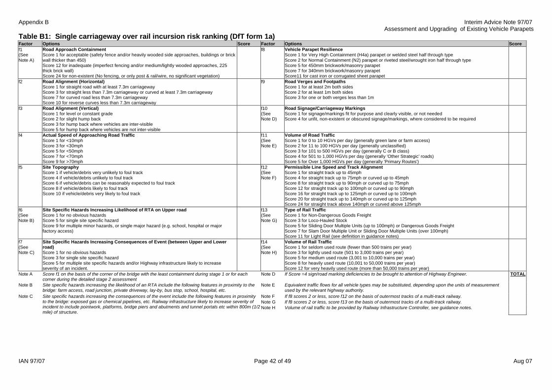
Appendix B Interim Advice Note 97/07Assessment and Upgrading of Existing Vehicle Parapets
IAN 97/07 Page 42 of 49 Aug 07
Table B1: Single carriageway over rail incursion risk ranking (DfT form 1a)Factor Options Score Factor Options Scoref1(SeeNote A)
Road Approach ContainmentScore 1 for acceptable (safety fence and/or heavily wooded side approaches, buildings or brickwall thicker than 450)Score 12 for inadequate (imperfect fencing and/or medium/lightly wooded approaches, 225thick brick wall)Score 24 for non-existent (No fencing, or only post & rail/wire, no significant vegetation)
f8 Vehicle Parapet ResilienceScore 1 for Very High Containment (H4a) parapet or welded steel half through typeScore 2 for Normal Containment (N2) parapet or riveted steel/wrought iron half through typeScore 5 for 450mm brickwork/masonry parapetScore 7 for 340mm brickwork/masonry parapetScore11 for cast iron or corrugated sheet parapet
f2 Road Alignment (Horizontal)Score 1 for straight road with at least 7.3m carriagewayScore 3 for straight less than 7.3m carriageway or curved at least 7.3m carriagewayScore 7 for curved road less than 7.3m carriagewayScore 10 for reverse curves less than 7.3m carriageway
f9 Road Verges and FootpathsScore 1 for at least 2m both sidesScore 2 for at least 1m both sidesScore 3 for one or both verges less than 1m
f3 Road Alignment (Vertical)Score 1 for level or constant gradeScore 2 for slight hump backScore 3 for hump back where vehicles are inter-visibleScore 5 for hump back where vehicles are not inter-visible
f10(SeeNote D)
Road Signage/Carriageway MarkingsScore 1 for signage/markings fit for purpose and clearly visible, or not neededScore 4 for unfit, non-existent or obscured signage/markings, where considered to be required
f4 Actual Speed of Approaching Road TrafficScore 1 for <10mphScore 3 for <30mphScore 5 for <50mphScore 7 for <70mphScore 9 for >70mph
f11(SeeNote E)
Volume of Road TrafficScore 1 for 0 to 10 HGVs per day (generally green lane or farm access)Score 2 for 11 to 100 HGVs per day (generally unclassified)Score 3 for 101 to 500 HGVs per day (generally C or B class)Score 4 for 501 to 1,000 HGVs per day (generally 'Other Strategic' roads)Score 5 for Over 1,000 HGVs per day (generally 'Primary Routes')
f5 Site TopographyScore 1 if vehicle/debris very unlikely to foul trackScore 4 if vehicle/debris unlikely to foul trackScore 6 if vehicle/debris can be reasonably expected to foul trackScore 8 if vehicle/debris likely to foul trackScore 10 if vehicle/debris very likely to foul track
f12(SeeNote F)
Permissible Line Speed and Track AlignmentScore 1 for straight track up to 45mphScore 4 for straight track up to 75mph or curved up to 45mphScore 8 for straight track up to 90mph or curved up to 75mphScore 12 for straight track up to 100mph or curved up to 90mphScore 16 for straight track up to 125mph or curved up to 100mphScore 20 for straight track up to 140mph or curved up to 125mphScore 24 for straight track above 140mph or curved above 125mph
f6(SeeNote B)
Site Specific Hazards Increasing Likelihood of RTA on Upper roadScore 1 for no obvious hazardsScore 5 for single site specific hazardScore 9 for multiple minor hazards, or single major hazard (e.g. school, hospital or majorfactory access)
f13(SeeNote G)
Type of Rail TrafficScore 1 for Non-Dangerous Goods FreightScore 3 for Loco-Hauled StockScore 5 for Sliding Door Multiple Units (up to 100mph) or Dangerous Goods FreightScore 7 for Slam Door Multiple Unit or Sliding Door Multiple Units (over 100mph)Score 11 for Light Rail (see definition in guidance notes)
f7(SeeNote C)
Site Specific Hazards Increasing Consequences of Event (between Upper and Lowerroad)Score 1 for no obvious hazardsScore 3 for single site specific hazardScore 5 for multiple site specific hazards and/or Highway infrastructure likely to increaseseverity of an incident.
f14(SeeNote H)
Volume of Rail TrafficScore 1 for seldom used route (fewer than 500 trains per year)Score 3 for lightly used route (501 to 3,000 trains per year)Score 5 for medium used route (3,001 to 10,000 trains per year)Score 8 for heavily used route (10,001 to 50,000 trains per year)Score 12 for very heavily used route (more than 50,000 trains per year)
Note A Score f1 on the basis of the corner of the bridge with the least containment during stage 1 or for eachcorner during the detailed stage 2 assessment
Note D If Score =4 sign/road marking deficiencies to be brought to attention of Highway Engineer. TOTAL
Note B Site specific hazards increasing the likelihood of an RTA include the following features in proximity to thebridge: farm access, road junction, private driveway, lay-by, bus stop, school, hospital, etc.
Note E Equivalent traffic flows for all vehicle types may be substituted, depending upon the units of measurementused by the relevant highway authority.
Note F If f8 scores 2 or less, score f12 on the basis of outermost tracks of a multi-track railway.Note G If f8 scores 2 or less, score f13 on the basis of outermost tracks of a multi-track railway.
Note C Site specific hazards increasing the consequences of the event include the following features in proximityto the bridge: exposed gas or chemical pipelines, etc. Railway infrastructure likely to increase severity ofincident to include pointwork, platforms, bridge piers and abutments and tunnel portals etc within 800m (1/2mile) of structure.
Note H Volume of rail traffic to be provided by Railway Infrastructure Controller, see guidance notes.

Appendix B Interim Advice Note 97/07Assessment and Upgrading of Existing Vehicle Parapets
IAN 97/07 Page 43 of 49 Aug 07
Table B2: Motorway and dual carriageway over rail incursion risk ranking (DfT form 1b)Factor Options Score Factor Options Scoref1(SeeNote A)
Road Approach ContainmentScore 1 for Very High Containment (H4a) vehicle restraint system (safety barrier or extended vehicle parapet etc.)of adequate length.Score 6 for Normal Containment (N2) vehicle restraint system of adequate length or compliant with "length ofneed".Score 12 for sub-standard, defective or damaged or inadequate length approach safety barriers (See Note A)Score 24 for non-existent or significantly sub-standard vehicle restraint system.
f8 Vehicle Parapet ResilienceScore 1 for Very High Containment (H4a) vehicle parapet or equivalentScore 2 for a Normal Containment (N2) parapet (of either 1.25 or 1.5 m height) or a sub-standardparapet protected by a normal containment safety barrierScore 3 for a Normal Containment (N2) parapet (of 1 m height)Score 5 for an unprotected 450mm brickwork/masonry vehicle parapetScore 7 for an unprotected 340mm brickwork/masonry vehicle parapetScore11 for an unprotected defective or sub-standard vehicle parapet
f2 Road Alignment (Horizontal & Vertical)Score 1 for full standard sight stopping distance (ssd), full width lanes, straight & constant gradeScore 3 for full standard ssd, some curves and undulations but standard horizontal and vertical alignmentsScore 7 for sub-standard ssd or narrow, sub-standard vertical and horizontal alignments
f9 Hard Shoulders, Edge Strips, Road Verges and FootpathsScore 1 for full width hard shoulder (>3.0m) and 1.5m or greater vergeScore 2 for reduced hard shoulder (3.0m<2.5m) or 1m edge strip and 1.5m or greaterverge/footpath measured at the narrowest pointScore 3 for narrow hard shoulder (< 2.5m) or edge strip and verge/footpath less than 2mmeasured at the narrowest point
f3 Sleep-Related Vehicle AccidentsScore 1 for no obvious risk factorScore 3 for site on featureless rural road with the minimal services and/or minimal distractions for drivers at theside of the roadScore 5 for a bridge on a sweeping right hand bend, sweeping left hand bend with no central reserve safetybarriers or a site at the end of a long route (e.g. eastbound of eastern end of M20)Score 9 for a combination of any of the above factors
f10(SeeNote D)
Carriageway MarkingsScore 1 for edge markings, rumble strips and "cats eyes" in accordance with current standardsScore 4 for non-existent, inadequate or obscured markings, worn, buried or over painted rumblestrips at a location where considered to be required
f4 Actual Speed Of Approaching TrafficScore 1 for 50 – 60Score 3 for 61 – 70Score 6 for > 70
f11(SeeNote E)
Combined Volume of Road Traffic on both CarriagewaysScore 1 for < 20,000 vehicles per day (vpd)Score 2 for 20,000 - 40,000 vpdScore 3 for 40,000 - 60,000 vpdScore 5 for 61,000 - 120,000 vpdScore 8 for Over 120,000 vpd
f5 Site TopographyScore 1 if vehicle/debris very unlikely to foul track from the bridge approachScore 4 if vehicle/debris unlikely to foul track from the bridge approachScore 6 if vehicle/debris can be reasonably expected to foul track from the bridge approachScore 8 if vehicle/debris likely to foul track from the bridge approachScore 10 if vehicle/debris very likely to foul track from the bridge approach
f12(SeeNote F)
Permissible Line Speed and Track AlignmentScore 1 for straight track up to 45mphScore 4 for straight track up to 75mph or curved up to 45mphScore 8 for straight track up to 90mph or curved up to 75mphScore 12 for straight track up to 100mph or curved up to 90mphScore 16 for straight track up to 125mph or curved up to 100mphScore 20 for straight track up to 140mph or curved up to 125mphScore 24 for straight track above 140mph or curved above 125mph
f6(SeeNote B)
Site Specific Hazards Increasing Likelihood of RTAScore 1 for no obvious hazardsScore 5 for single site specific hazardScore 7 for multiple minor hazards, or single major hazard ( e.g. junctions, steep slopes, sharp bends)Score 9 for multiple major hazards
f13 Type of Rail TrafficScore 1 for Non-Dangerous Goods FreightScore 3 for Loco-Hauled StockScore 5 for Sliding Door Multiple Units (up to 100mph) or Dangerous Goods FreightScore 7 for Slam Door Multiple Unit or Sliding Door Multiple Units (over 100mph)Score 11 for Light Rail (see definition in guidance notes)
f7(SeeNote C)
Site Specific Hazards Increasing Consequences of EventScore 1 for no obvious hazardsScore 3 for single site specific hazardScore 5 for multiple site specific hazards and/or Railway infrastructure likely to increase severity of an incident.
f14 Volume of Rail TrafficScore 1 for seldom used route (fewer than 500 trains per year)Score 3 for lightly used route (501 to 3,000 trains per year)Score 5 for medium used route (3,001 to 10,000 trains per year)Score 8 for heavily used route (10,001 to 50,000 trains per year)Score 12 for very heavily used route (more than 50,000 trains per year)
Note A This factor is to be considered in conjunction with f5 Site Topography to determine the "length of need". Note D If Score = 4 road marking deficiencies to be brought to attention of maintaining authorityNote B Site specific hazards increasing the likelihood of an RTA include the following features in proximity to the bridge:
interchange, road junction, lay-by, emergency service vehicle recesses, lane drops and no hard shoulder etc. Considerationshould be given to increasing the score by two if there is no adequate carriageway lighting.
Note E The percentage of HGVs on major roads is typically about 10%. Assessors should increase thescore by one band if HGVs form 12% or more of the total traffic.
TOTAL
Note C Site specific hazards increasing the consequences of the event include the following features in proximity to the bridge:exposed gas or chemical pipelines, etc. Railway infrastructure likely to increase severity of incident to include pointwork,platforms, bridge piers and abutments and tunnel portals etc within 800m (1/2 mile) of structure.
Note F Line speed, volume and type of rail traffic to be provided by Railway Infrastructure Controller, seeguidance notes.

Appendix B Interim Advice Note 97/07Assessment and Upgrading of Existing Vehicle Parapets
IAN 97/07 Page 44 of 49 Aug 07
Table B3: Single carriageway over road incursion risk ranking (from DfT and TRL forms)Factor Options Score Factor Options Scoref1(SeeNote A)
Upper Road Approach ContainmentScore 1 for acceptable (safety fence and/or heavily wooded side approaches, buildings or brick wallthicker than 450)Score 12 for inadequate (imperfect fencing and/or medium/lightly wooded approaches, 225 thick brickwall)Score 24 for non-existent (No fencing, or only post & rail/wire, no significant vegetation)
f8 Vehicle Parapet Resilience on Upper RoadScore 1 for Very High Containment (H4a) parapet or welded steel half through typeScore 2 for Normal Containment (N2) parapet or riveted steel/wrought iron half through typeScore 5 for 450mm brickwork/masonry parapetScore 7 for 340mm brickwork/masonry parapetScore11 for cast iron or corrugated sheet parapet
f2 Upper Road Alignment (Horizontal)Score 1 for straight road with at least 7.3m carriagewayScore 3 for straight less than 7.3m carriageway or curved at least 7.3m carriagewayScore 7 for curved road less than 7.3m carriagewayScore 10 for reverse curves less than 7.3m carriageway
f9 Road Verges and Footpaths on Upper RoadScore 1 for at least 2m both sidesScore 2 for at least 1m both sidesScore 3 for one or both verges less than 1m
f3 Upper Road Alignment (Vertical)Score 1 for level or constant gradeScore 2 for slight hump backScore 3 for hump back where vehicles are inter-visibleScore 5 for hump back where vehicles are not inter-visible
f10(SeeNote D)
Road Signage/Carriageway Markings on Upper RoadScore 1 for signage/markings fit for purpose and clearly visible, or not neededScore 4 for unfit, non-existent or obscured signage/markings, where considered to be required
f4 Actual Speed of Approaching Road Traffic on Upper roadScore 1 for <10mphScore 3 for <30mphScore 5 for <50mphScore 7 for <70mphScore 9 for >70mph
f11(SeeNote E)
Volume of Road Traffic on Upper RoadScore 1 for 0 to 10 HGVs per day (generally green lane or farm access)Score 2 for 11 to 100 HGVs per day (generally unclassified)Score 3 for 101 to 500 HGVs per day (generally C or B class)Score 4 for 501 to 1,000 HGVs per day (generally 'Other Strategic' roads)Score 5 for Over 1,000 HGVs per day (generally 'Primary Routes')
f5 Site TopographyScore 1 if vehicle/debris very unlikely to foul lower roadScore 4 if vehicle/debris unlikely to foul lower roadScore 6 if vehicle/debris can be reasonably expected to foul lower roadScore 8 if vehicle/debris likely to foul lower roadScore 10 if vehicle/debris very likely to foul lower road
f12 Actual Speed of Traffic on Lower RoadScore 1 for < 10mphScore 4 for < 30mphScore 8 for < 50mphScore 10 for < 70mphScore 12 for > 70mph
f6(SeeNote B)
Site Specific Hazards Increasing Likelihood of RTAScore 1 for no obvious hazardsScore 5 for single site specific hazardScore 9 for multiple minor hazards, or single major hazard (e.g. school, hospital or major factory access)
f13(SeeNote G)
Site Specific Hazards Increasing Consequences of Event on Lower RoadOne-way roads Two-way roads
No hazards Score 1 Score 1Single hazard Score 3 Score 5Two hazards Score 5 Score 73 or more hazards/queuing Score 7 Score 9
f7(SeeNote C)
Site Specific Hazards Increasing Consequences of Event (between Upper and Lower Road)Score 1 for no obvious hazardsScore 3 for single site specific hazardScore 5 for multiple site specific hazards and/or lower road infrastructure likely to increase severity of anincident.
f14(SeeNote F)
Combined Volume of Road Traffic on both Carriageways of Lower RoadScore 1 for < 20,000 vehicles per day (vpd)Score 5 for 20,000 - 40,000 vpdScore 7 for 40,000 - 60,000 vpdScore 9 for 61,000 - 120,000 vpdScore 11 for Over 120,000 vpd
Note D If Score =4 sign/road marking deficiencies to be brought to attention of Highway Engineer.Note A Score f1 on the basis of the corner of the bridge with the least containment during stage 1 or for each cornerduring the detailed stage 2 assessment Note E Equivalent traffic flows for all vehicle types may be substituted, depending upon the units of
measurement used by the relevant highway authority.
TOTAL
Note B Site specific hazards increasing the likelihood of an RTA include the following features in proximity to the bridge:farm access, road junction, private driveway, lay-by, bus stop, school, hospital, etc.
Note F The percentage of HGVs on major roads is typically about 10%. Assessors should increase the score byone band if HGVs form 12% or more of the total traffic.
Note C Site specific hazards increasing the consequences of the event include the following features in proximity to thebridge: exposed gas or chemical pipelines, etc. Highway infrastructure likely to increase severity of incident toinclude bridge piers, abutments and tunnel portals etc within 800m (1/2 mile) of structure.
Note G The hazards on the lower road leading to increased consequences could include the presence ofpedestrians, road and/or verge width (inability to avoid a vehicle blocking the road), poor or no lighting,reduced sight lines (e.g. bends or vegetation) and adjacent land use (e.g. housing, schools). likelihood ofqueues, etc.

Appendix B Interim Advice Note 97/07Assessment and Upgrading of Existing Vehicle Parapets
IAN 97/07 Page 45 of 49 Aug 07
Table B4: Motorway and dual carriageway over road incursion risk ranking (TRL fig 2.1)Factor Options Score Factor Options Scoref1(SeeNote A)
Upper Road Approach ContainmentScore 1 for Very High Containment (H4a) vehicle restraint system (safety barrier or extended vehicle parapet etc.)of adequate length.Score 6 for Normal Containment (N2) vehicle restraint system of adequate length or compliant with "length ofneed".Score 12 for sub-standard, defective or damaged or inadequate length approach safety barriers (See Note A)Score 24 for non-existent or significantly sub-standard vehicle restraint system.
f8 Vehicle Parapet Resilience on Upper RoadScore 1 for Very High Containment (H4a) vehicle parapet or equivalentScore 2 for a Normal Containment (N2) parapet (of either 1.25 or 1.5 m height) or a sub-standardparapet protected by a normal containment safety barrierScore 3 for a Normal Containment (N2) parapet (of 1 m height)Score 5 for an unprotected 450mm brickwork/masonry vehicle parapetScore 7 for an unprotected 340mm brickwork/masonry vehicle parapetScore11 for an unprotected defective or sub-standard vehicle parapet
f2 Upper Road Alignment (Horizontal & Vertical)Score 1 for full standard sight stopping distance (ssd), full width lanes, straight & constant gradeScore 3 for full standard ssd, some curves and undulations but standard horizontal and vertical alignmentsScore 7 for sub-standard ssd or narrow, sub-standard vertical and horizontal alignments
f9 Hard Shoulders, Edge Strips, Road Verges and Footpaths on Upper RoadScore 1 for full width hard shoulder (>3.0m) and 1.5m or greater vergeScore 2 for reduced hard shoulder (3.0m<2.5m) or 1m edge strip and 1.5m or greaterverge/footpath measured at the narrowest pointScore 3 for narrow hard shoulder (< 2.5m) or edge strip and verge/footpath less than 2mmeasured at the narrowest point
f3 Sleep-Related Vehicle Accidents on Upper RoadScore 1 for no obvious risk factorScore 3 for site on featureless rural road with the minimal services and/or minimal distractions for drivers at theside of the roadScore 5 for a bridge on a sweeping right hand bend, sweeping left hand bend with no central reserve safetybarriers or a site at the end of a long route (e.g. eastbound of eastern end of M20)Score 9 for a combination of any of the above factors
f10(SeeNote D)
Carriageway Markings on Upper RoadsScore 1 for edge markings, rumble strips and "cats eyes" in accordance with current standardsScore 4 for non-existent, inadequate or obscured markings, worn, buried or over painted rumblestrips at a location where considered to be required
f4 Actual Speed Of Approaching Traffic on Upper RoadScore 1 for 50 – 60Score 3 for 61 – 70Score 6 for > 70
f11(SeeNote E)
Combined Volume of Road Traffic on both Carriageways of Upper RoadScore 1 for < 20,000 vehicles per day (vpd)Score 2 for 20,000 - 40,000 vpdScore 3 for 40,000 - 60,000 vpdScore 5 for 61,000 - 120,000 vpdScore 8 for Over 120,000 vpd
f5 Site TopographyScore 1 if vehicle/debris very unlikely to foul lower road from the bridge approachScore 4 if vehicle/debris unlikely to foul lower road from the bridge approachScore 6 if vehicle/debris can be reasonably expected to foul lower road from the bridge approachScore 8 if vehicle/debris likely to foul lower road from the bridge approachScore 10 if vehicle/debris very likely to foul lower road from the bridge approach
f12 Actual Speed of Traffic on Lower RoadScore 1 for < 10mphScore 4 for < 30mphScore 8 for < 50mphScore 10 for < 70mphScore 12 for > 70mph
f6(SeeNote B)
Site Specific Hazards Increasing Likelihood of RTA on Upper RoadScore 1 for no obvious hazardsScore 5 for single site specific hazardScore 7 for multiple minor hazards, or single major hazard ( e.g. junctions, steep slopes, sharp bends)Score 9 for multiple major hazards
f13(SeeNote F)
Site Specific Hazards Increasing Consequences of Event on Lower RoadOne-way roads Two-way roads
No hazards Score 1 Score 1Single hazard Score 3 Score 5Two hazards Score 5 Score 73 or more hazards/queuing Score 7 Score 9
f7(SeeNote C)
Site Specific Hazards Increasing Consequences of Event (between Upper and Lower Road)Score 1 for no obvious hazardsScore 3 for single site specific hazardScore 5 for multiple site specific hazards and/or lower road infrastructure likely to increase severity of an incident.
f14(SeeNote E)
Combined Volume of Road Traffic on both Carriageways of Lower RoadScore 1 for < 20,000 vehicles per day (vpd)Score 5 for 20,000 - 40,000 vpdScore 7 for 40,000 - 60,000 vpdScore 9 for 61,000 - 120,000 vpdScore 11 for Over 120,000 vpd
Note A This factor is to be considered in conjunction with f5 Site Topography to determine the "length of need". Note D If Score = 4 road marking deficiencies to be brought to attention of maintaining authorityNote E The percentage of HGVs on major roads is typically about 10%. Assessors should increase the
score by one band if HGVs form 12% or more of the total traffic.Note B Site specific hazards increasing the likelihood of an RTA include the following features in proximity to the bridge:
interchange, road junction, lay-by, emergency service vehicle recesses, lane drops and no hard shoulder etc. Considerationshould be given to increasing the score by two if there is no adequate carriageway lighting.
TOTAL
Note C Site specific hazards increasing the consequences of the event include the following features in proximity to the bridge:exposed gas or chemical pipelines, etc. Highway infrastructure likely to increase severity of incident to include bridge piers,abutments and tunnel portals etc within 800m (1/2 mile) of structure.
Note F The hazards on the lower road leading to increased consequences could include the presence ofpedestrians, road and/or verge width (inability to avoid a vehicle blocking the road), poor or nolighting, reduced sight lines (e.g. bends or vegetation) and adjacent land use (e.g. housing,schools). likelihood of queues, etc.

Appendix C Interim Advice Note 97/07 Assessment and Upgrading of Existing Vehicle Parapets
IAN 97/07 Page 46 of 49 Aug 07
Appendix C: Identification of Substandard BACO Parapets
C1 Following the adoption of BS 6779: Part 1 1992, a series of tests were undertaken on BACO normal containment parapets. Consultants were then commissioned by the HA to provide an independent review of the testing. C2 The conclusions reached were that the normal containment BACO 300/400 series parapets (without RF 158/01B modifications) do not, in many respects, meet the normal containment standards of BS 6779-1, but do meet the requisite standards for low containment systems. BACO low containment parapets were not tested, but the review concluded that it is likely, based on the evidence of testing on normal containment parapets, that low containment parapets of similar design would not meet the requirements of BS 6779-1. (Note that the designations “normal containment” and “low Containment” used in this Appendix when relating to the substandard BACO parapets relate to the BS 6779 containment classes.) C3 The retesting of BACO parapets following the adoption of BS 6779: Part 1 1992 had shown that a number of types do not comply with the standard. These parapets are ones supplied prior to 1994 and are:
a) Normal containment parapets - Series 300 and 400, P1(113), P2(113) and P5; b) Low containment parapets - P2(80).
The only exception to the above is in the parapet design which uses vertical posts supplied from January 1988 and with water cooled (as opposed to pre-1986 air cooled) extrusions. These may be satisfactorily modified in accordance with Amendment No 1: December 1993 to BS 6779: Part 1:1992. Any BACO 300/400 Series parapets installed after 31 March 1993 should have been modified either during fabrication or on site prior to acceptance. C4 Parapets with vertical posts and manufactured entirely from water cooled alloy may be modified in-situ in accordance with Amendment No 1: December 1993 to BS 6779: Part 1: 1992 as an alternative to replacement. The modification consists of cutting slots in the rear of the posts and fitting additional post to rail clips. Modification is acceptable on technical grounds as an alternative to replacement provided the parapet is in good condition. However, as it is often difficult to provide the slots in the posts without removing them from the structure. Consequently, the overall cost of modification may be similar to full parapet replacement. C5 Despite various attempted modifications to the posts and post-rail connections and further retesting, it had not proven possible to find a practical way of modifying the substandard designs to make them compliant with BS 6779-1. There are two basic configurations for the 300/400 Series:
� Parapets with inclined posts angled towards the traffic face. � Parapets with vertical posts
C6 CHE Memorandum 11/93, “BACO Parapet Systems”, identified that BACO aluminium parapet standard designs, which had been in accepted between 1967 and 1993, required modifications to their designs to meet the requirements of the fourth revision to BE 5 and BS 6779-1.

Appendix C Interim Advice Note 97/07 Assessment and Upgrading of Existing Vehicle Parapets
IAN 97/07 Page 47 of 49 Aug 07
These revised details were provided on BACO drawings DB2112-009 (issue 5), DB2112-010 (issue 4), DB2112-011 (issue 5) and RF 158/01. Parapets fabricated to earlier issues of the above drawings were prohibited from use on the trunk road network after 31 March 1993.

Appendix D Interim Advice Note 97/07 Assessment and Upgrading of Existing Vehicle Parapets
IAN 97/07 Page 48 of 49 Aug 07
Appendix D: Assessment of Parapet Supporting Members
D1 Background This Appendix provides criteria for the assessment of parapet supporting members relating to the local effects and global effects of vehicle collision loading. These assessment requirements differ from the design requirements of clauses 6.7.1 and 6.7.2 of BD 37/01, and partially supersede clause 4.46 of TD 19/06. D2 Local Effects of Vehicle Collision D2.1 A fundamental principle in the design of new structures is that impact destruction of a parapet does not cause damage to parapet supporting members. This principle ensures that impact destructed parapets can be replaced relatively readily. D2.2 For the assessment or upgrading of parapets to existing structures, the ‘do-nothing’ option is generally preferred. This option accepts the impact damage to the supporting structure when it occurs and repairs would then be undertaken, preferably at the same time as replacing/repairing the parapet. Therefore the assessment of parapet supporting members should be governed by the absolute minimum strength requirement, covered in section D3. D2.3 In exceptional cases where damage to the supporting member could lead to global consequence (i.e., collapse of a bridge, or full closure of a highway bridge in the period before repairs are completed), the assessment of parapet supporting members should be governed by the requirements of clauses 6.7.1 and 6.7.2 of BD 37/01, subject to agreement of the Technical Approval Authority. D3 Absolute Minimum Strength Assessment Criteria The absolute minimum strength requirement for a parapet supporting member is the strength necessary to ensure the containment level requirement for the parapet is provided. The relevant assessment criteria are given below:
� Single impact force and force height obtained from table D1. The force is applied normal to the line of the parapet and at a height measured above the level of the supporting member.
� Single wheel load obtained from table D2. The load is applied in a position which produces the most severe effect, and should be distributed over a circular or square contact area, assuming an effective pressure of 1.1 N/mm2.
� γfl = 1.00 and γf3 = 1.00 at the ultimate limit state. Simple methods of assessment tend to yield conservative results. Should an initial simplified assessment indicate member failure, more refined techniques should be considered, subject to agreement with the Technical Approval Authority.

Appendix D Interim Advice Note 97/07 Assessment and Upgrading of Existing Vehicle Parapets
IAN 97/07 Page 49 of 49 Aug 07
Table D1 Assessment Impact Force (kN) versus Dynamic Deflection
Dynamic Deflection of Road Restraint System (m) Containment Class 0.00 0.20 0.40 0.60 0.80 1.00 1.20 1.40 1.60 1.80 2.00
Force Height (m)
N1 69 52 42 35 30 27 24 21 19 18 17
N2 130 99 79 67 57 50 45 40 37 34 31 0.60
H1 101 87 77 68 62 56 52 48 44 42 39
H2 139 127 117 108 100 94 88 83 79 74 71 0.75
H4a 329 295 268 245 225 209 195 182 171 162 153 0.90
Notes: 1. Dynamic deflection is as defined in Fig 1.1 of TD 19/06. 2. Guidance on dynamic deflections for approved parapets may be obtained from the parapet
manufacturers or from the Highways Agency’s Vehicle Restraints and Risk Management Team. 3. For older N1 or N2 containment metal parapets, dynamic deflection may be assumed to be 0.6m. 4. Force height is measured above the level of the parapet supporting member.
Table D2 Vertical Wheel Load (kN) versus Containment Class
Containment Class
N1 N2 H1 H2 H4a
25 25 60 60 100
D4 Global Effects of Vehicle Collision D4.1 Global effects need not be considered for bridges where the superstructure is fully integral with the substructure. D4.2 Normal (N1/N2) and higher containment (H1/H2) parapets and safety barriers do not generally require consideration of global effects, except for H1/H2 containment rigid concrete barriers. D4.3 All very-high containment (H4a) parapets/safety barriers and H1/H2 containment rigid concrete barriers require consideration of the following global assessment criteria:
� Single 500kN horizontal force. The force is applied at the top of and normal to the line of the parapet, over a length of 3m.
� γfl = 1.00 and γf3 = 1.00 at the serviceability limit state. � γfl = 1.25 and γf3 = 1.00 at the ultimate limit state.
The force should only be considered in relation to possible destabilisation of the structure, typically caused by failure of bearings or other deck restraint features for bridges, and geotechnical failure for retaining walls. D4.4 Assessment failure of bearings/restraint features should generally be considered acceptable, provided that such failure is not likely to lead to global consequence (i.e., collapse or full closure of a bridge/retaining wall in the period before repairs are completed).