interim storage of radioactive waste packages library cataloguing in publication data interim...
TRANSCRIPT

Interim Storage of Radioactive Waste Packages
INTERNATIONAL ATOMIC ENERGY AGENCY, VIENNA, 1998
TTEECCHHNNIICCAALL RREEPPOORRTTSS SSEERRIIEESS NNoo.. 390
ISBN 92–0–103698–1ISSN 0074–1914
Interim
Sto
rage o
f Rad
ioactive W
aste Packag
esTech
nical R
epo
rts Series N
o.390
INTERIM STORAGEOF RADIOACTIVEWASTE PACKAGES

The following States are Members of the International Atomic Energy Agency:
AFGHANISTANALBANIAALGERIAARGENTINAARMENIAAUSTRALIAAUSTRIABANGLADESHBELARUSBELGIUMBOLIVIABOSNIA AND
HERZEGOVINABRAZILBULGARIABURKINA FASOCAMBODIACAMEROONCANADACHILECHINACOLOMBIACOSTA RICACOTE D’IVOIRECROATIACUBACYPRUSCZECH REPUBLICDEMOCRATIC REPUBLIC
OF THE CONGODENMARKDOMINICAN REPUBLICECUADOREGYPTEL SALVADORESTONIAETHIOPIAFINLANDFRANCEGABONGEORGIAGERMANYGHANAGREECEGUATEMALA
HAITIHOLY SEEHUNGARYICELANDINDIAINDONESIAIRAN, ISLAMIC REPUBLIC OF IRAQIRELANDISRAELITALYJAMAICAJAPANJORDANKAZAKHSTANKENYAKOREA, REPUBLIC OFKUWAITLATVIALEBANONLIBERIALIBYAN ARAB JAMAHIRIYALIECHTENSTEINLITHUANIALUXEMBOURGMADAGASCARMALAYSIAMALIMALTAMARSHALL ISLANDSMAURITIUSMEXICOMONACOMONGOLIAMOROCCOMYANMARNAMIBIANETHERLANDSNEW ZEALANDNICARAGUANIGERNIGERIANORWAYPAKISTANPANAMA
PARAGUAYPERUPHILIPPINESPOLANDPORTUGALQATARREPUBLIC OF MOLDOVAROMANIARUSSIAN FEDERATIONSAUDI ARABIASENEGALSIERRA LEONESINGAPORESLOVAKIASLOVENIASOUTH AFRICASPAINSRI LANKASUDANSWEDENSWITZERLANDSYRIAN ARAB REPUBLICTHAILANDTHE FORMER YUGOSLAV
REPUBLIC OF MACEDONIATUNISIATURKEYUGANDAUKRAINEUNITED ARAB EMIRATESUNITED KINGDOM OF
GREAT BRITAIN AND NORTHERN IRELAND
UNITED REPUBLICOF TANZANIA
UNITED STATESOF AMERICA
URUGUAYUZBEKISTANVENEZUELAVIET NAMYEMENYUGOSLAVIAZAMBIAZIMBABWE
The Agency’s Statute was approved on 23 October 1956 by the Conference on the Statute of theIAEA held at United Nations Headquarters, New York; it entered into force on 29 July 1957. TheHeadquarters of the Agency are situated in Vienna. Its principal objective is “to accelerate and enlarge thecontribution of atomic energy to peace, health and prosperity throughout the world’’.
© IAEA, 1998
Permission to reproduce or translate the information contained in this publication may beobtained by writing to the International Atomic Energy Agency, Wagramer Strasse 5, P.O. Box 100,A-1400 Vienna, Austria.
Printed by the IAEA in AustriaOctober 1998
STI/DOC/010/390

INTERIM STORAGEOF RADIOACTIVEWASTE PACKAGES
TECHNICAL REPORTS SERIES No. 390
INTERNATIONAL ATOMIC ENERGY AGENCYVIENNA, 1998

VIC Library Cataloguing in Publication Data
Interim storage of radioactive waste packages. — Vienna : International AtomicEnergy Energy, 1998.
p. ; 24 cm. — Technical reports series, ISSN 0074–1914; no. 390)STI/DOC/010/390ISBN 92–0–103698–1Includes bibliographical references.
1. Radioactive wastes—Packaging. I. International Atomic Energy Agency.II. Series: Technical reports series (International Atomic Energy Agency);389.
VICL 98–00204

Nuclear power production and the use of radioactive materials and ionizingradiation in industry, agriculture, medicine and research generate radioactive wastes.These wastes must be safely managed at all stages prior to and including ultimate safedisposal. Storage is an integral part of the waste management process. While thestorage of conditioned waste is normally described as interim storage, for someMember States this will probably be fairly long term, even to the point of de factodisposal. Somewhere between ten and fifty years will most likely be required forstorage until a repository can be constructed and licensed, or until radioactivity hasdecayed to a sufficiently low level for disposal as cleared waste.
Since the storage of radioactive waste had not been adequately covered intechnical publications of the International Atomic Energy Agency, it was decided toreview past and current experience and prepare a report to provide technical guidanceto Member States on safe and economic methods for storage of radioactive wastepackages.
This report covers all the principal aspects of production and interim storage ofradioactive waste packages. The latest design solutions of waste storage facilities andthe operational experiences of developed countries are described and evaluated inorder to assist developing Member States in decision making and design andconstruction of their own storage facilities. The report provides a source of technicalinformation for all organizations involved in the waste management process,including waste generators, designers and operators of conditioning and storagefacilities, and national regulatory bodies.
The original draft report was prepared by five consultants: H. Brücher,Forschungszentrum Jülich GmbH (Germany), N. Dellero, NUSYS–Transnucléaire(France), R. Reynders, Belgoprocess (Belgium), P. Richards, British Nuclear Fuelsplc (United Kingdom), and R. Stupka, Los Alamos National Laboratory (USA). TheTechnical Committee meeting (TCM), at which the report was reviewed and muchadditional information contributed, was attended by 19 experts and held in Viennafrom 23 to 27 September 1996. After the TCM the same group of consultants, exceptR. Reynders, finalized the report.
The IAEA is grateful to those who have taken part in the preparation of thisreport, particularly the consultants and P. Risoluti (Italy), Chairman of the TCM. TheIAEA officer responsible for the report was V.S. Tsyplenkov from the Division ofNuclear Fuel Cycle and Waste Technology.
FOREWORD

EDITORIAL NOTE
Although great care has been taken to maintain the accuracy of information containedin this publication, neither the IAEA nor its Member States assume any responsibility forconsequences which may arise from its use.
The mention of names of specific companies or products (whether or not indicated asregistered) does not imply any intention to infringe proprietary rights, nor should it beconstrued as an endorsement or recommendation on the part of the IAEA.

CONTENTS
1. INTRODUCTION . . . . . . . . . . . . . . . . . . . . . . . . . . . . . . . . . . . . . . . . . 1
1.1. Background . . . . . . . . . . . . . . . . . . . . . . . . . . . . . . . . . . . . . . . . . 11.2. Objective . . . . . . . . . . . . . . . . . . . . . . . . . . . . . . . . . . . . . . . . . . . 21.3. Scope . . . . . . . . . . . . . . . . . . . . . . . . . . . . . . . . . . . . . . . . . . . . . . 21.4. Structure . . . . . . . . . . . . . . . . . . . . . . . . . . . . . . . . . . . . . . . . . . . 2
2. SAFETY PRINCIPLES AND REQUIREMENTSFOR WASTE PACKAGE STORAGE . . . . . . . . . . . . . . . . . . . . . . . . . . . 3
2.1. Safety principles . . . . . . . . . . . . . . . . . . . . . . . . . . . . . . . . . . . . . . 32.2. Requirements for waste packages . . . . . . . . . . . . . . . . . . . . . . . . . 5
2.2.1. Waste form, container and waste package . . . . . . . . . . . . . . 52.2.2. Waste acceptance criteria . . . . . . . . . . . . . . . . . . . . . . . . . . 92.2.3. Waste specifications . . . . . . . . . . . . . . . . . . . . . . . . . . . . . . 14
2.3. Requirements for storage facilities . . . . . . . . . . . . . . . . . . . . . . . . 142.3.1. Design requirements . . . . . . . . . . . . . . . . . . . . . . . . . . . . . . 142.3.2. Operational requirements . . . . . . . . . . . . . . . . . . . . . . . . . . 17
2.4. Safety assessment of storage facilities . . . . . . . . . . . . . . . . . . . . . . 182.5. Quality assurance . . . . . . . . . . . . . . . . . . . . . . . . . . . . . . . . . . . . . 19
3. PRODUCTION OF WASTE PACKAGES . . . . . . . . . . . . . . . . . . . . . . . 21
3.1. Categories of radioactive waste . . . . . . . . . . . . . . . . . . . . . . . . . . . 213.1.1. Low and intermediate level waste . . . . . . . . . . . . . . . . . . . . . 213.1.2. High level waste and spent fuel . . . . . . . . . . . . . . . . . . . . . . 223.1.3. Spent sealed radiation sources . . . . . . . . . . . . . . . . . . . . . . . 23
3.2. Brief overview of volume reduction processes . . . . . . . . . . . . . . . . 233.2.1. Thermal treatment processes . . . . . . . . . . . . . . . . . . . . . . . . 243.2.2. Compaction of solid waste . . . . . . . . . . . . . . . . . . . . . . . . . . 243.2.3. Melting . . . . . . . . . . . . . . . . . . . . . . . . . . . . . . . . . . . . . . . . 263.2.4. Evaporation of liquid waste . . . . . . . . . . . . . . . . . . . . . . . . . 26
3.3. Brief overview of conditioning processes . . . . . . . . . . . . . . . . . . . 263.3.1. Cementation . . . . . . . . . . . . . . . . . . . . . . . . . . . . . . . . . . . . . 273.3.2. Bituminization . . . . . . . . . . . . . . . . . . . . . . . . . . . . . . . . . . . 273.3.3. Polymerization . . . . . . . . . . . . . . . . . . . . . . . . . . . . . . . . . . 293.3.4. Vitrification . . . . . . . . . . . . . . . . . . . . . . . . . . . . . . . . . . . . . 29
3.4. Examples of waste packages . . . . . . . . . . . . . . . . . . . . . . . . . . . . . 29

4. STORAGE FACILITIES . . . . . . . . . . . . . . . . . . . . . . . . . . . . . . . . . . . . 31
4.1. General categories . . . . . . . . . . . . . . . . . . . . . . . . . . . . . . . . . . . . . 314.2. Storage of low contact dose rate LILW . . . . . . . . . . . . . . . . . . . . . 31
4.2.1. Civil construction . . . . . . . . . . . . . . . . . . . . . . . . . . . . . . . . 314.2.2. Package handling . . . . . . . . . . . . . . . . . . . . . . . . . . . . . . . . 374.2.3. Emplacement . . . . . . . . . . . . . . . . . . . . . . . . . . . . . . . . . . . 384.2.4. Record keeping . . . . . . . . . . . . . . . . . . . . . . . . . . . . . . . . . 38
4.3. Storage of high contact dose rate LILW . . . . . . . . . . . . . . . . . . . . 384.3.1. Civil construction . . . . . . . . . . . . . . . . . . . . . . . . . . . . . . . . 384.3.2. Package handling . . . . . . . . . . . . . . . . . . . . . . . . . . . . . . . . 454.3.3. Emplacement . . . . . . . . . . . . . . . . . . . . . . . . . . . . . . . . . . . 454.3.4. Record keeping . . . . . . . . . . . . . . . . . . . . . . . . . . . . . . . . . 46
4.4. Storage of vitrified HLW and spent fuel . . . . . . . . . . . . . . . . . . . . 514.4.1. Civil construction . . . . . . . . . . . . . . . . . . . . . . . . . . . . . . . . 514.4.2. Package handling . . . . . . . . . . . . . . . . . . . . . . . . . . . . . . . . 554.4.3. Emplacement . . . . . . . . . . . . . . . . . . . . . . . . . . . . . . . . . . . 554.4.4. Record keeping . . . . . . . . . . . . . . . . . . . . . . . . . . . . . . . . . 55
4.5. Storage of spent sealed radiation sources . . . . . . . . . . . . . . . . . . . . 55
5. OPERATIONAL EXPERIENCE AND OPTIMAL STORAGEPRACTICES . . . . . . . . . . . . . . . . . . . . . . . . . . . . . . . . . . . . . . . . . . . . . 55
5.1. Operational control of storage conditions . . . . . . . . . . . . . . . . . . . 585.2. Surveillance of waste packages . . . . . . . . . . . . . . . . . . . . . . . . . . . 60
5.2.1. Certification . . . . . . . . . . . . . . . . . . . . . . . . . . . . . . . . . . . . 605.2.2. Control of inventory location . . . . . . . . . . . . . . . . . . . . . . . 605.2.3. Inspection . . . . . . . . . . . . . . . . . . . . . . . . . . . . . . . . . . . . . 60
5.3. Examples of waste package deterioration during storage . . . . . . . . 625.3.1. Waste containers . . . . . . . . . . . . . . . . . . . . . . . . . . . . . . . . 625.3.2. Gas generation . . . . . . . . . . . . . . . . . . . . . . . . . . . . . . . . . . 625.3.3. Physical and chemical changes . . . . . . . . . . . . . . . . . . . . . . 625.3.4. Change in radiation dose rate . . . . . . . . . . . . . . . . . . . . . . . 635.3.5. Accelerated deterioration due to mechanical damage . . . . . 635.3.6. Accelerated deterioration due to package corrosion . . . . . . 635.3.7. Galvanic reaction . . . . . . . . . . . . . . . . . . . . . . . . . . . . . . . . 63
5.4. Storage facilities in selected Member States . . . . . . . . . . . . . . . . . 64
6. WASTE PACKAGE MANAGEMENT OPTIONS AFTERTHE LICENSED STORAGE PERIOD . . . . . . . . . . . . . . . . . . . . . . . . . 64
6.1. General management options . . . . . . . . . . . . . . . . . . . . . . . . . . . . 646.2. Survey, inspection and testing . . . . . . . . . . . . . . . . . . . . . . . . . . . . 65
6.2.1. Necessity for survey, inspection and testing . . . . . . . . . . . . 656.2.2. Records review and survey of packages . . . . . . . . . . . . . . . 666.2.3. Non-destructive testing methods . . . . . . . . . . . . . . . . . . . . . 676.2.4. Destructive testing methods . . . . . . . . . . . . . . . . . . . . . . . . 69
6.3. Actions required after the licensed storage period . . . . . . . . . . . . . 696.3.1. Certification for transport and disposal . . . . . . . . . . . . . . . . 696.3.2. Reconditioning of waste packages . . . . . . . . . . . . . . . . . . . 706.3.3. Retrieval for disposal as very low radioactive waste
or cleared waste . . . . . . . . . . . . . . . . . . . . . . . . . . . . . . . . . 716.3.4. Prolonged storage . . . . . . . . . . . . . . . . . . . . . . . . . . . . . . . . 73
7. RECOMMENDED MEASURES TO ENSURE OPTIMAL PERFORMANCE OF WASTE PACKAGES DURING STORAGE . . . . 73
7.1. Waste generation and characterization . . . . . . . . . . . . . . . . . . . . . . 747.2. Storage facilities . . . . . . . . . . . . . . . . . . . . . . . . . . . . . . . . . . . . . . 747.3. Provision for retrieval of waste packages . . . . . . . . . . . . . . . . . . . . 75
8. CONCLUSIONS . . . . . . . . . . . . . . . . . . . . . . . . . . . . . . . . . . . . . . . . . . 75
APPENDIX: STORAGE FACILITIES IN SELECTEDMEMBER STATES . . . . . . . . . . . . . . . . . . . . . . . . . . . . . . . . 76
REFERENCES . . . . . . . . . . . . . . . . . . . . . . . . . . . . . . . . . . . . . . . . . . . . . . 87
CONTRIBUTORS TO DRAFTING AND REVIEW . . . . . . . . . . . . . . . . . . . . 89
1. INTRODUCTION
1.1. BACKGROUND
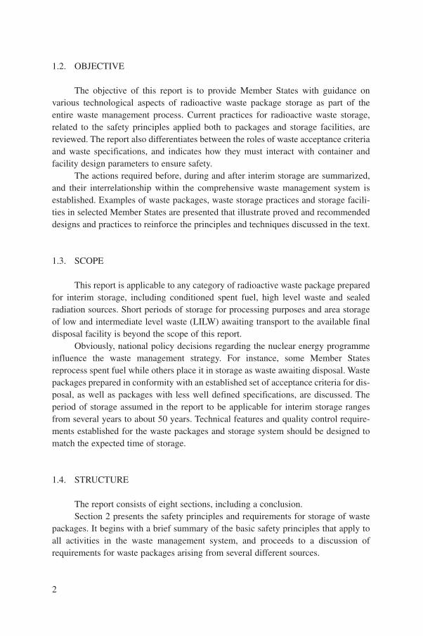
A waste management system is developed using an approach that addressesthe safety of all the steps and operations involved as a whole, rather than the safetyof each separate step. The basic steps in radioactive waste management, dependingon the type of waste, are pretreatment, treatment, conditioning, storage and dispos-al. The steps are interrelated. Each step must be carefully designed and performed,and the effects of future radioactive waste management activities, particularly dis-posal, taken into account when any separate radioactive waste management activityis being considered. Conditioning of radioactive waste involves those operations thattransform radioactive waste into a form suitable for handling, transport and dispos-al. However, if for some reason disposal of waste packages cannot be made imme-diately after conditioning (e.g. if a disposal facility is not available or if radioactivityin waste packages must decay to lower levels), interim storage of waste packages isrequired and must be arranged in such a way as to ensure the integrity of radioactivewaste packages and their suitability for further disposal after retrieval from a storagefacility.
The core of the waste management system is the technology which is appliedto the waste from generation to disposal. Waste management technology has receivedconsiderable attention in Member States in view of the importance of the linkbetween nuclear power and nuclear applications on one hand, and, on the other, thesafe management of radioactive waste resulting from the use of nuclear energy.Application of this technology is important to ensure radiological safety for workersand the public and to avoid accidents or unnecessary releases of radionuclides asso-ciated with radioactive waste. In countries with a developed nuclear industry, quali-fied conditioning processes exist. Wastes conditioned by these processes are normal-ly qualified for long term safety and integrity. Usually, processes that use a matrix areconsidered as definitive for the waste form, and further conditioning only involvespackaging.
To date, most aspects of waste processing and disposal of low, intermediateand high level radioactive waste have been addressed in various IAEA publications.However, the subject of radioactive waste storage has not been adequatelyaddressed as an integral part of the waste management system ultimately leading todisposal. Also, the integrated requirements of the disposal system that result in thedevelopment of waste package criteria and specifications, and the impact of inter-im storage on the waste as an engineered system, have largely been ignored in theliterature.
1
1.2. OBJECTIVE
The objective of this report is to provide Member States with guidance onvarious technological aspects of radioactive waste package storage as part of theentire waste management process. Current practices for radioactive waste storage,related to the safety principles applied both to packages and storage facilities, arereviewed. The report also differentiates between the roles of waste acceptance criteriaand waste specifications, and indicates how they must interact with container andfacility design parameters to ensure safety.
The actions required before, during and after interim storage are summarized,and their interrelationship within the comprehensive waste management system isestablished. Examples of waste packages, waste storage practices and storage facili-ties in selected Member States are presented that illustrate proved and recommendeddesigns and practices to reinforce the principles and techniques discussed in the text.
1.3. SCOPE
This report is applicable to any category of radioactive waste package preparedfor interim storage, including conditioned spent fuel, high level waste and sealedradiation sources. Short periods of storage for processing purposes and area storageof low and intermediate level waste (LILW) awaiting transport to the available finaldisposal facility is beyond the scope of this report.
Obviously, national policy decisions regarding the nuclear energy programmeinfluence the waste management strategy. For instance, some Member Statesreprocess spent fuel while others place it in storage as waste awaiting disposal. Wastepackages prepared in conformity with an established set of acceptance criteria for dis-posal, as well as packages with less well defined specifications, are discussed. Theperiod of storage assumed in the report to be applicable for interim storage rangesfrom several years to about 50 years. Technical features and quality control require-ments established for the waste packages and storage system should be designed tomatch the expected time of storage.
1.4. STRUCTURE
The report consists of eight sections, including a conclusion.Section 2 presents the safety principles and requirements for storage of waste
packages. It begins with a brief summary of the basic safety principles that apply toall activities in the waste management system, and proceeds to a discussion ofrequirements for waste packages arising from several different sources.
2

Section 3 describes treatment and conditioning methods for the main categoriesof radioactive waste that may require storage. It includes a brief overview of condi-tioning processes and presents representative samples of waste packages from severalMember States.
Section 4 addresses the three major types of storage facility now in use byMember States, and relates their experience in interim storage by presenting exam-ples of existing interim storage facilities for LILW, spent fuel and high level waste(HLW).
Section 5 is based on the operational experience of Member States in wastestorage operations including control of storage conditions, surveillance of wastepackages and observation of the behaviour of waste packages during storage.
Section 6 addresses the issue of retrieval of waste packages from storagefacilities. The functions of record keeping, package testing, inspection, and generalmanagement options are discussed.
Section 7 recommends technical and administrative measures that will ensureoptimal performance of waste packages subject to various periods of interim storage.
Section 8 concludes with international experience in designing and operatingstorage facilities.
The Appendix gives details of storage facilities in selected Member States.
2. SAFETY PRINCIPLES AND REQUIREMENTSFOR WASTE PACKAGE STORAGE
2.1. SAFETY PRINCIPLES
The design and operation of storage facilities in each Member State must com-ply with the basic safety principles set up in the IAEA Safety Standard, “InternationalBasic Safety Standards for Protection against Ionizing Radiation and for the Safety ofRadiation Sources” [1] and the Safety Fundamentals, “The Principles of RadioactiveWaste Management” [2]. The former is based on guidelines issued by theInternational Commission on Radiological Protection (ICRP) in Publication 46 [3]and Publication 60 [4]. Together, these principles and guidelines dictate the behaviourof the national waste management system, of which the storage step is an integralpart. More specifically, storage of radioactive waste, like all other steps of waste man-agement, must comply with the three main principles of radiation protection [1]:
• The normal exposure of employees and the public must be restricted and mustnot exceed specified dose limits;
3

• The practice must be justified in terms of the risk incurred versus the benefit tosociety;
• The practice, while keeping exposures as low as reasonably achievable(ALARA), must be optimized to provide maximum benefit for the costincurred.
Additional waste management principles are also important. Briefly, these basicprinciples [2], as applied to the storage of radioactive waste, include:
• Protection beyond national borders;• Management of the storage operation within, and compatible with, the existing
legal framework;• Avoidance of shifting the burden of storage and ultimate disposal of the waste
to future generations;• Minimal generation of radioactive waste, designed to facilitate its management
by incorporating principles such as recycle/reuse, selection and control ofradioactive materials, and design of facilities with decommissioning in mind;
• Safety of the storage facility;• Protection of the environment from the storage operation.
The national regulatory authority may place additional constraints on the wastemanagement process with regard to storage. For instance, requirements for managingradioactive wastes mixed with hazardous chemical or biological substances mayimpose additional constraints on interim storage, including facility design and admin-istrative controls that govern waste handling.
National policies in nuclear energy generation and applications of radionuclidesin research, medicine and industry greatly affect the amount and characteristics ofwaste requiring management as well as the way it must be managed. A typical exam-ple is the decision of a Member State whether or not to reprocess spent nuclear fuel.
A consistent approach should be taken by the national authority regarding thesafety of all nuclear facilities within its borders in order to ensure compliance withinternational safety standards. Operation of any facility, including one for storage,should be supported by a systematic safety assessment that addresses: (a) potentialaccidents and measures taken to limit their consequences (if necessary); (b) site selec-tion and other design features as they relate to safety; (c) provisions for surveillanceand periodic reassessment of the safety of the facility. In particular, a principle ofnuclear safety in relation to a single waste package and the storage facility designmust be complied with. Industrial safety standards must also be incorporated in thedesign and operation of storage facilities.
Finally, the storage facility must function as an integrated part of the wholewaste management system. To assess compliance of the storage facility with the basic
4

safety principles and objectives, a licensing process including safety and environ-mental impact assessments must be part of the waste management system.
2.2. REQUIREMENTS FOR WASTE PACKAGES
A wide variety of waste packages are used in Member States to meet the needsof the nuclear industry and research. Many specialized types are designed and manu-factured with the needs of a specific user in mind; however, others, such as the TypeA 200 L drum package, must meet the needs of a wide variety of users. The packagemanufacturer should ensure that the waste container and waste form are able to com-bine reliably to form a waste package that meets a defined set of technical require-ments for various potential waste management stages including storage, transport anddisposal.
Radioactive waste may exist in several forms when it passes through the treat-ment and conditioning processes. It may exist sequentially as raw, treated, immobi-lized and fully conditioned waste. While in storage it should be expected to retain itsform and suitability for transport and disposal for up to 50 years without subsequentreconditioning. This is accomplished through the interaction of three sets of criteria:the waste acceptance criteria (WAC), the waste form and container specifications, andthe design and operating requirements of the storage facility.
2.2.1. Waste form, container and waste package
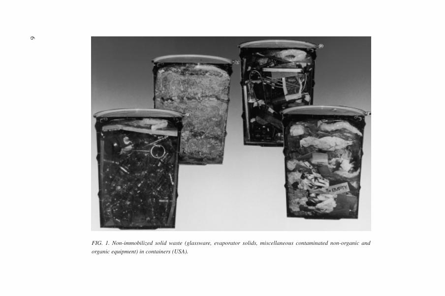
The waste form is the waste in its physical and chemical form after treatmentand/or immobilization (resulting in a solid product) prior to packaging [5].Immobilization of waste, i.e. the conversion of a waste into a waste form by solidifi-cation, embedding or encapsulation, may be required, depending on the type of waste.Waste immobilization reduces the potential for migration or dispersion of radionu-clides during handling, transport, storage and disposal. Examples of waste as theymay arise, for instance, from the operation of radiochemical laboratories, are given inFig. 1 for non-immobilized waste and in Fig. 2 for immobilized waste.
The container is the vessel into which the waste form is placed for handling,transport, storage and/or eventual disposal. It is essential that the quality of the con-tainer is not detrimental to the safety of handling, transport, storage and disposalwhen exposed to a corrosive environment. The container must also retain its integrityin an accident scenario. For LILW, detailed descriptions of containers are given inRef. [6].
Waste containers may be designed for relatively short or long lives, dependingon their role in limiting or preventing the release of radionuclides in a disposal sys-tem for a limited time span. Regardless of the intended life in the disposal facility,
5
6
FIG. 1. Non-immobilized solid waste (glassware, evaporator solids, miscellaneous contaminated non-organic and
organic equipment) in containers (USA).

7
FIG. 2. Metallic scrap material embedded in cement (UK).

8
FIG. 3. Standard cylindrical drums used for packaging LILW (Argentina). Left: 200 L stainless steel drum; right: 400 L carbonsteel drum with an epoxy paint inside and outside.
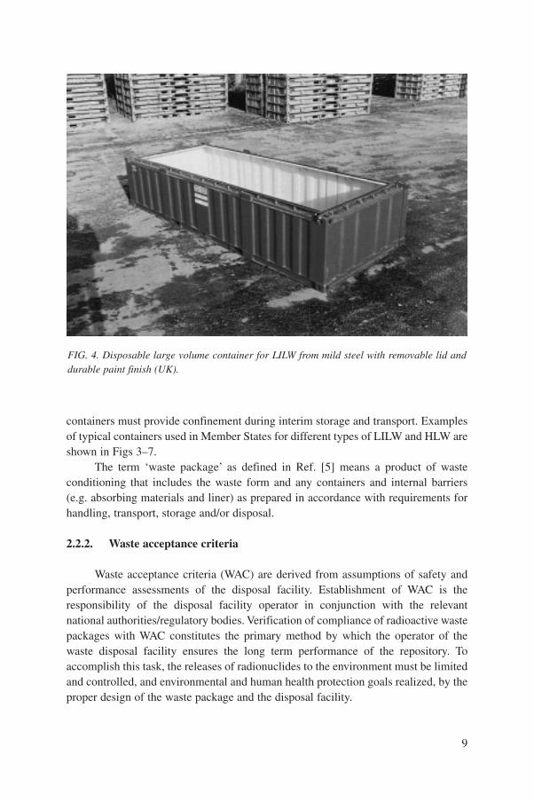
containers must provide confinement during interim storage and transport. Examplesof typical containers used in Member States for different types of LILW and HLW areshown in Figs 3–7.
The term ‘waste package’ as defined in Ref. [5] means a product of wasteconditioning that includes the waste form and any containers and internal barriers(e.g. absorbing materials and liner) as prepared in accordance with requirements forhandling, transport, storage and/or disposal.
2.2.2. Waste acceptance criteria
Waste acceptance criteria (WAC) are derived from assumptions of safety andperformance assessments of the disposal facility. Establishment of WAC is theresponsibility of the disposal facility operator in conjunction with the relevantnational authorities/regulatory bodies. Verification of compliance of radioactive wastepackages with WAC constitutes the primary method by which the operator of thewaste disposal facility ensures the long term performance of the repository. Toaccomplish this task, the releases of radionuclides to the environment must be limitedand controlled, and environmental and human health protection goals realized, by theproper design of the waste package and the disposal facility.
9
FIG. 4. Disposable large volume container for LILW from mild steel with removable lid anddurable paint finish (UK).

10
FIG. 5. 1500 L stainless steel container for cemented cladding hulls and end fittings (France).

There is a situation when waste packages are produced in the absence of a dis-posal facility and therefore no applicable WAC are available to guide the design andproduction of the packages. In this case the packages may be produced and fully char-acterized in accordance with the best engineering assumptions based on the experi-ence and practice of other Member States. In such circumstances long term storage ofthese waste packages is a certain outcome, and it is inevitable that the storage facilitywill develop a set of acceptance criteria of their own for waste packages generatedunder these conditions.
In addition, transport regulations [7] place a set of overlapping criteria on thewaste packages which will be transported from production to storage or from storageto disposal. These include surface dose rate, surface contamination limits, weight,size, total activity and structural integrity requirements. This means that the WACconstitute an agreement among the waste generator, transporter, and waste storage ordisposal facility operator regarding the minimum characteristics of each wastepackage produced for storage and/or disposal. Meeting these criteria determines howthe waste packages will perform under conditions of storage, transport, and ultimate-ly emplacement in a disposal facility. In the past, WAC were thought to be of primaryimportance only in determining and ensuring the ultimate performance of the wastedisposal system. Under conditions of long term storage awaiting disposal, the
11
FIG. 6. Shielded cast iron cask, typically used for transport and storage of high dose rateLILW (Germany).

12
FIG. 7. 150 L stainless steel canister for vitrified HLW (France).

package must successfully maintain its characteristics under two very different envi-ronments. At either the interim or the long term storage facility, the facility operatorcan refuse to receive waste that does not comply with the requirements of WAC asdirected by the operator’s licence conditions.
Typical WAC address a wide range of physical, chemical and radiologicalcriteria essential to the safe and effective performance of the waste package. Sincesome packages have a limited design life outside the disposal facility, the WAC havebecome very important in ensuring that, after storage, the waste package can still besafely moved. Since a waste package consists of a waste form and a container, aspecific set of technical requirements can be addressed to them separately and to thewaste package as a whole. For a waste form, these criteria concern but are not limitedto the following, depending on the disposal site requirements:
• Waste composition• Chemical durability• Immobilization and/or stabilization• Structural stability• Respirable fraction• Distribution of activity.
WAC for waste containers may cover the following parameters:
• Internal pressure• Mechanical integrity• Properties affecting primary confinement• Venting• Compatibility with the waste form.
Each waste package must meet a general set of criteria in addition to require-ments specific to the waste form and waste container. WAC applied for wastepackages generally include the following:
• Seal integrity• Free liquids• Gas generation• Flammability• Radionuclide inventory• Fissile mass• Decay heat• Radiation dose rate and surface contamination• Configuration and weight• Identification.
13
Waste packages may be subject to additional constraints due to limitations orspecial conditions present at the storage facility that do not exist at the disposal site.For instance, floor loading and entrance dimensions may limit the package size andweight permitted for storage. When a disposal site is available and has WAC, therequirements must be compared and the most conservative set chosen for the wastepackages.
2.2.3. Waste specifications
Waste package specifications are the set of detailed quantitative requirements tobe satisfied by each package, indicating the procedure by which it may be determinedwhether the specified requirements are satisfied. Where the WAC for the disposalfacility have not been defined, or waste packages must be fully characterized, it maybe necessary to develop waste package specifications in place of the WAC. Thesespecifications are considered as design output, and are intended to control the radio-logical, physical and chemical characteristics of the waste to be produced, processedor accepted from another organization. Waste specifications are usually orientedtowards the performance of waste packages or control of operating facility processesand may be used as a contractual vehicle to control subcontracted conditioningoperations. Waste specifications, like the WAC, should take into account intendedstorage/disposal facility parameters and transport regulations and should incorporaterelevant parameters of the WAC, if they exist.
While WAC are generally facility or site specific and may embrace manydifferent types of package, waste package specifications are specific to a particulartype of package and are used to define the characteristics and attributes of a wastepackage.
2.3. REQUIREMENTS FOR STORAGE FACILITIES
2.3.1. Design requirements
The main functions of a storage facility for conditioned radioactive waste are toprovide safe custody of the waste packages and to protect both operators and the gen-eral public from any radiological hazards associated with radioactive waste. Thedesign of storage facilities will have to meet the national regulatory standards andbasic safety principles, as described in Ref. [1]. The design proposed should followthese general principles and aim to reduce the probability of accidents to an “as lowas practicable” level. In this context, the facility should be capable of maintaining the
14

“as-received” integrity of the waste package until it is retrieved for disposal. Thestorage facility must protect the waste from environmental conditions, includingextremes of humidity, heat and cold, or any other environmental condition whichwould degrade the waste form or container. Local climatic conditions may result inthe need for cooling or dehumidifying the store atmosphere to avoid possible deteri-oration of the waste packages.
Storage requirements mandate external dose rate and contamination limits forwaste packages to be accepted by the facility in order to protect personnel. A maxi-mum allowable dose rate at the surface of each package should be defined for specif-ic interim storage facilities or parts of facilities. In other respects the storage facilityusually adheres to the waste acceptance requirements of the disposal facility. Thestorage facility should minimize radiation exposure to on-site personnel throughappropriate siting and shielding.
The storage facility may be associated with an area for inspection (includingsorting and/or non-destructive examination), certification and labelling of waste pack-ages. The storage facility is usually divided into areas where low contact dose ratepackages are stored, areas where packages not meeting WAC are stored, and ashielded area where high contact dose rate packages are kept secure. The design ofthe facility usually permits package stacking, sorting and visual inspection.
Provision for maintaining a database keeping chain-of-custody for each wastepackage in storage must be included in the design. Key information about the wastepackage should include the total radionuclide content, the waste matrix used forimmobilization, the treatment and/or conditioning method (as applicable), and theunique package designator. A hard copy file should follow the waste package fromconditioning to its final disposal.
Storage facilities should be designed to allow control of any contaminationfrom gaseous or liquid releases. Adequate ventilation should be available to deal withany gas generation during normal operation or possible accident conditions. Provisionfor fire protection and for decontaminating individual containers and facility surfacesshould also be made. Arrangements must be made to treat (or transport to a process-ing facility) potential accidental releases.
Storage facilities are often built in anticipation of a need, and have inherent lim-itations in the types and quantities of waste packages they might receive. Of necessity,storage facilities will provide space for non-immobilized waste (NIW) as well asimmobilized and fully conditioned waste. Also, the initial design often needs to bechanged in terms of space required, floor loadings and type of waste storage required.Because of these uncertainties, design criteria for storage facilities should take intoaccount the following considerations:
(a) Adequate segregated storage should be provided for NIW and/or conditionedradioactive waste with anticipation of future storage needs if several types of
15

package are stored in the same facility. These needs are, in turn, determined bythe waste processing requirements and capabilities and the availability ofspecific treatment or disposal facilities, as well as package storage life and con-ditions. NIW should be stored in a form and manner that limit the risk of dis-persion. NIW must be segregated according to its hazard level. Waste with shortlived radionuclides that is to be held for decay must be segregated in a way thatpermits discharge as cleared waste when clearance levels are attained, as autho-rized by the regulatory authority.
(b) Emplacement, storage and retrieval of waste packages should be designed tokeep exposure of personnel as low as reasonably achievable.
(c) The storage capacity of the facility must be designed to accept the maximumoperational holdings anticipated from the system. The store should containenough spare capacity to accept the contents of another storage unit whoseintegrity may be breached or suspect. Appropriate equipment for transferbetween operational and spare units must be available.
(d) In the design of storage facilities for conditioned radioactive waste, considera-tion must also be given to:
• Waste package handling;• Clear identification of stored waste packages and record keeping;• Provision for inspection and monitoring of stored waste;• Provision to prevent possible degradation of waste packages during
storage;• Provision for adequate environmental conditions (heating, cooling, humidity
control) to ensure proper conservation of waste packages during theirstorage in the facility;
• Provision for cooling heat generating waste;• Provision for fire protection where combustible waste is present;• Provision for gas dissipation if gas generation is anticipated;• Provision for criticality control where a considerable amount of fissile
material is present in the waste;• Provision for prevention of unauthorized access;• Retrieval of the waste for further treatment, immobilization or disposal, or
in the event of an accident which requires relocation of the waste; • Maintenance.
If buildings are planned to be used for storage of radioactive waste theyshould be situated above the groundwater level, and certainly not in a flood plain.In cases where a subsurface storage facility is designed, this facility should beconstructed with appropriate systems to protect against in-leakage of ground-water.
16

2.3.2. Operational requirements
The operations to be carried out in a storage facility will be limited to receipt,emplacement, integrity control (if required), retrieval, and preparation for dispatch ofwaste packages. The interim storage operations are essentially passive for the longperiod of time when waste packages are pending retrieval (most probably in bulk)until the repository facility is established. All operations concerned with storagemust be carried out within the written authorized procedures.
2.3.2.1. Receipt and emplacement
The waste receipts should be programmed in advance. The store manager mustexamine the information to confirm that the waste package is acceptable for storage(e.g. correct packaging standard, radiation levels within limits). If the package isunacceptable, the details are to be recorded and the documents returned to the con-signor with an explanation or a request for further information. Package acceptancequalification conditions should include, but not be limited to: maximum allowableweight per package; mechanical resistance for the stacking of packages; satisfactorycorrosion resistance of the container material; sufficient resistance to a standard firetest; and no loss of integrity after a drop test from a height related to the packagetransport condition. The above tests are designed [7] to confirm the adequacy of thestandard packaging design and should be performed occasionally during waste pack-age production.
In the case of external contamination, the package must be decontaminated andrechecked before interim storage is authorized.
On acceptance, the equipment required for transport of the waste package tothe store should be selected, and the store operator should proceed with thisequipment and prepare the appropriate documentation to store the waste. Theoperator must be trained in the appropriate methods of radiological protection andin the use of radiation protective equipment if needed during handling of the wastepackage. At the store, a suitable location for the waste package should be identifiedand the location details recorded. The waste package would be placed in the chosenlocation. Segregation of waste types is desirable to facilitate a planned retrieval forfurther treatment or any unplanned retrieval that is revealed as necessary byperiodic inspections for possible degradation of waste containers, and in casethere are categories of waste to be placed eventually in particular repository loca-tions.
The information provided by the consignor and the storage location of the pack-age are incorporated in the central store records.
17
2.3.2.2. Integrity control
Adequate conditions for safe storage of waste packages should be maintainedduring the storage phase to avoid deterioration. Proper radiation protection measuresmust be applied to ensure that exposure to workers and the public is kept as low asreasonably achievable and that there is no contamination of the store or the wastepackages. Monitoring should be undertaken to ensure that contamination has notoccurred. The frequency of the monitoring will depend upon the quantity and type ofthe waste packages.
The records of the store inventory should be kept up to date, and the store con-tents periodically checked against the records.
2.3.2.3. Retrieval and dispatch
Following receipt of a request to retrieve a package from storage, the store man-ager should obtain the details of the particular waste package from the store’s recordsand pass them to the appropriate party. If the details are in order the package may beaccepted for removal from the storage facility. Once the store manager has authorizedthe release of the waste package, it is retrieved from the store and taken to the dis-patch area. Here, the package should be monitored for radiation levels before it isreleased. The details of the waste package will be transferred to the transport recordsand the waste packaged for transport in accordance with the requirements of thetransport regulations [7]. The package storage records should be amended to recordthe date of dispatch and the receiving party.
2.4. SAFETY ASSESSMENT OF STORAGE FACILITIES
A safety assessment must be carried out as part of the licensing process todemonstrate that the storage facility complies with regulatory requirements. Theassessment will need to demonstrate that doses and risks remain within establishedcriteria and meet the ALARA principle. Safety will need to be assessed for both nor-mal operations and foreseeable accident conditions. The safety assessment must con-sider incidents arising both from internal process related events (e.g. internal fire,dropped waste packages, failure of containment of the waste packages) and fromexternal hazards (aircraft crashes, transport accidents away from the facility, earth-quakes, tornadoes and external fires).
The first stage of the assessment involves looking at radiological safety quali-tatively to obtain a preliminary overview of the facility design concept. From thisreview, sensitive areas of design and/or operations may be identified, and any suchareas can be subjected to a more rigorous quantitative safety assessment.
18

While the intermediate level waste (ILW) store will contain large inventories ofradioactivity, the fact that the wastes have been immobilized in a stable matrix shouldresult in a low accident risk. If the concentration of fissile material in the wastes ishigh (a concern of nuclear safety), the criticality risk will need to be assessed. TheNIW store may contain smaller inventories of activity but the fact that those wastesare not immobilized in a stable matrix may result in a higher risk owing to a greaterrelease fraction being available in the event of an accident.
The safety impact due to the receipt of an externally contaminated waste pack-age should also be assessed. Possible causes of contamination are failure of a seal orsealing mechanism, overfilling of the container, or failure of the manual inspectionprocedure for contamination checking prior to emplacement into the store.Engineered and administrative controls incorporated to mitigate such an event shouldbe addressed.
The safety assessment of a storage facility should consider degradation or fail-ure of the waste package, which could occur for several reasons, including: corrosionof the container; gas generation in the waste matrix; decomposition of the waste pack-age due to adverse change in the waste form; or an accident resulting in mechanicalstress on the package in excess of its design capability. Other operational failures oraccidents that may have to be considered in the safety assessment include but are notlimited to ventilation failure, spills, fire, electrical failure and natural disaster.Assessments of possible accidents should correspond to the national objectives forsafety analysis. Even if such failures or accidents should occur, the consequenceswould be of minor importance because the low mobility of the immobilized activitywould result in minimal airborne or waterborne contamination.
The design of the facility should prevent water in-leakage to the store.
2.5. QUALITY ASSURANCE
In practice, quality assurance (QA) as applied to the storage of radioactive wasteis divided into five principles of equal importance: general principles of QA in radio-active waste management, QA programme considerations, management, performance,and assessment.
Taking these general QA principles into account ensures that each step in theprocess (in this case, waste storage) (a) reflects health, safety and environmental con-cerns, (b) considers special needs or requirements of the national system, and (c) ade-quately anticipates the system’s requirements where uncertainties exist. It is alsonecessary to test the ability of the system to deal with storage issues created by wastegenerated outside the system.
Programme considerations require: formalization of the QA programme toensure that storage facilities are designed, constructed and operated safely in
19

accordance with specified requirements, and that they receive waste packages pro-duced in the same way; that WAC for transport, interim storage and disposal are met;and that all regulations and conditions of the license are satisfied.
The QA management responsibility acknowledges that all work is a processthat can be planned, performed, assessed and improved. Although the individual per-forming the work is responsible for quality, it is the function of QA management, byproviding planning, organization, direction and control of the work, to remove barri-ers to success and promote a cycle of continuous improvement in products andprocesses.
QA performance for storage facilities includes such elements as design controland verification, peer review, data collection and software control, waste packagespecifications, and control of procured goods and services. QA for performance alsoassesses:
• Personnel performance and qualifications, and acceptance of items and ser-vices;
• Control of work processes, including the interfaces that exist between genera-tion, processing, treatment, storage, recovery and disposal of waste;
• Storage, handling and shipping, including the assessment of all controls placedon the handling, dispatch, decontamination, storage, packaging and transport inorder to prevent accidents, prevent container deterioration, and ensure thevalidity of analytical operations;
• Control of waste and operational status, including failed waste packages,identification and correction of substandard operational equipment and otheritems important to safety;
• Identification and control of items important to safety, including acceptanceinspection and testing;
• Inspection hold points, surveillance and process monitoring;• Identification of critical areas for inspection;• Test control and control of measuring and test equipment.
Finally, QA assessment, as applied to the storage stage, includes activities bymanagement for product verification, self-assessment and independent verification.However, QA applies to all elements of the waste management system, and canmeasure their interface and the system’s effectiveness. Years of experience haveshown that any management system left to itself will deteriorate over time. QAassessment therefore becomes the most important part of the QA programme,because it provides for measurement of programme effectiveness before, during andafter the storage stage of waste management, and for continuous improvement of thequality of the entire process.
20

3. PRODUCTION OF WASTE PACKAGES
3.1. CATEGORIES OF RADIOACTIVE WASTE
Radioactive waste is generated from the nuclear fuel cycle, medicine, industryand research activities. At least 95% of all radioactive waste generated is low andintermediate level waste. Other categories, such as high level waste including spentfuel declared as waste, are also produced, albeit at significantly lower volumes. Eachwaste category is described below.
3.1.1. Low and intermediate level waste
Radioactive waste in which the concentration or the quantity of radionuclidesis above the clearance levels established by the national regulatory authority, butwhich has a radionuclide content and thermal power below those of high level waste(HLW), is addressed as low and intermediate level wastes (LILW) [8]. LILW is oftenseparated into short lived and long lived waste. The term ‘long lived’ refers toradionuclides with half-lives usually greater than 30 years. As practised in severalMember States, short lived LILW may be disposed of in near surface disposalfacilities, whereas plans call for the disposal of long lived LILW in deep geologicalrepositories.
The boundary between short lived and long lived wastes cannot be specified ina universal manner with respect to concentration levels for radioactive waste disposal,because the levels will depend on the actual radioactive waste management optionand the properties of the individual radionuclides. However, in current practice withnear surface disposal in various countries, the activity concentration is limited to4000 Bq/g of long lived alpha emitters in individual radioactive waste packages, thuscharacterizing long lived waste which is planned to be disposed of in geologicalformations. This level has been determined on the basis of analyses for whichmembers of the public are assumed to access inadvertently a near surface repositoryafter an active institutional control period and perform typical construction activities(e.g. constructing a house or a road).
Applying the classification boundary, consideration should also be given toaccumulation and distribution of long lived radionuclides within a near surface repos-itory and to possible long term exposure pathways. Therefore, restrictions on activityconcentrations for long lived radionuclides in individual waste packages may be com-plemented by restrictions on average activity levels or by simple operational tech-niques, such as selective emplacement of higher activity waste packages within thedisposal facility. An average limit of about 400 Bq/g for long lived alpha emitters in
21

waste packages has been adopted by some countries for near surface disposal facili-ties.
In applying the classification system, attention should also be given to invento-ries of long lived radionuclides in a repository that emit beta and gamma radiation.For radionuclides such as 129I and 99Tc, allowable quantities or average concentra-tions within a repository depend strongly on site specific conditions. For this reason,national authorities may establish limits for long lived beta and gamma emittingradionuclides based on the analyses of specific disposal facilities.
For LILW the design criteria for storage facilities will be based mainly on doserate from the waste packages at the time of production and emplacement, rather thanwhether the waste is short or long lived, as this determines whether remote handlingand/or shielding is a requirement for package handling and store construction. InMember States with low national waste inventories it is recognized that a single storefor all LILW may be appropriate, in which case the store design should recognize thehigher specification for long lived waste. In the United States of America there is nospecial definition for intermediate level waste, and this waste is classified as ‘highactivity low level waste’. The requirements for storage of this waste would thereforebe based on its activity and surface dose rate. Depending on the dose rate, this wastemay be ‘contact handled’ (<2 mSv/h) or ‘remote handled’ (>2 mSv/h).
The possible hazard represented by the waste can often be significantly reducedby administratively controlling the waste as part of storage or after disposal. Althoughthe waste may contain high concentrations of short lived radionuclides, significantradioactive decay occurs during the period of institutional control. Concentrations oflong lived isotopes that will not decay significantly during the period of institutionalcontrol are controlled to low levels consistent with the radiotoxicity of the radionu-clides and requirements set out by the national authorities.
3.1.2. High level waste and spent fuel
High level waste (HLW), including spent fuel (SF) if declared as waste, is char-acterized by large concentrations of both short and long lived radionuclides, so that ahigh degree of isolation from the biosphere (e.g. geological disposal) is needed toensure long term safety. It generates significant quantities of heat from radioactivedecay, and normally continues to generate heat for several centuries.
An exact boundary level between LILW and HLW is difficult to quantifywithout precise planning data for many parameters such as the type of radionuclide,the decay period and the conditioning techniques. Typical activity levels are in therange 5 × 10⁴ to 5 × 10⁵ TBq/m3, corresponding to a heat generation rate of about2–20 kW/m3 for decay periods of up to about ten years after discharge of spent fuelfrom a reactor [8]. From this range, the lower value of about 2 kW/m3 is consideredreasonable to distinguish HLW from other radioactive waste classes, based on
22

the levels of decay heat emitted by HLW, such as those from reprocessing spentfuel.
The design criteria for storage facilities will be based mainly on dose rate fromthe packages as well as on decay heat, which has to be removed from the packages.Various external hazards should also be taken into account.
3.1.3. Spent sealed radiation sources
Sealed radiation sources usually fall into the category of LILW, and they areused for a variety of purposes, from instrument calibration and low power electricitygeneration to sterilization of medical tools and treatment of food for preservation.Their physical form may be a ceramic or a metal solid, or a salt solid of the radionu-clide encased in stainless steel.
High dose rate (>1 mSv/h) sources are usually housed in shielded containersconstructed of lead, steel or depleted uranium. High dose rate calibration of instru-ments is usually accomplished with a self-contained calibration. Other sources areused in medical applications as radiotherapy devices and contain 60Co or 137Cs asceramic pellets in a shielded head. A mechanical ram moves the pellet in and out ofthe shielding when therapy is required.
Extremely high dose rate sources are shipped to users in shielded transportcasks and returned in the same way after use.
As with other LILW, the design criteria for storage facilities for spent sealedradiation sources will be based mainly on their dose rate.
3.2. BRIEF OVERVIEW OF VOLUME REDUCTION PROCESSES
Once waste is produced it is important to reduce its volume so as to lower con-ditioning, transport, storage and disposal costs. However, the overall lifetime costs areof prime importance, and volume reduction must therefore be balanced against thecomplexity of the conditioning process. A large variety of volume reduction methodsare in use in Member States, generally based on mechanical, physical, chemical, bio-logical or thermal treatment. Selection of the most suitable method depends on thenature of the waste, the preliminary sorting and the storage/disposal criteria.
Volume reduction and treatment of low and intermediate liquid and solid wasteshave been described in several IAEA publications [9, 10]. Not covered in thosereports is the volume reduction of highly radioactive metallic waste, such as claddinghulls. However, implementation of a supercompaction technique for this waste isunder way in France. A selection of the most common volume reduction processes forliquid and solid LILW is given below.
23

3.2.1. Thermal treatment processes
Thermal treatment processes include a wide range of oxidative and pyrolytictechnologies which are extremely effective methods for volume reduction of com-bustible wastes. These processes provide a high reduction of mass (up to 10:1) andvolume (up to 100:1) by chemically destroying the organic portion of the waste,which often constitutes the bulk of combustible solid waste. Thermal treatment alsoyields residues containing concentrated radionuclides which are often more compati-ble with subsequent management steps (e.g. conditioning, transport, storage, disposal)than the original waste form. Another advantage of these processes is their versatilityin that they are able to accept and process a wide spectrum of dry solid wastes, organicliquid wastes, wet solid wastes and, to some extent, aqueous liquid wastes.
Incineration is the most common thermal treatment process and has beenapplied for over 40 years (e.g. the rotary kiln, controlled air and fluidized bedincinerators). Some other processes that do not employ open flame combustion butstill achieve thermal oxidation of organic materials are wet air oxidation, molten saltcombustion, molten glass combustion and vitrification. Numerous types and sizes ofincineration systems are in use in many countries for processing a variety of radio-active wastes, from low level power plant wastes and institutional biological wastesto high activity fuel reprocessing facility wastes. The end product of incineration, theash, may need additional treatment and conditioning, including compaction,immobilization, melting or emplacement in a high integrity container to meet storagerequirements [9].
3.2.2. Compaction of solid waste
Compaction is a process in which solid materials are mechanically compressedto achieve smaller volumes. Compactors are usually categorized by the force theydevelop for compressing the waste. ‘Low force’ or ‘low pressure’ compactors operateat less than 10 MN compaction force. They are capable of compressing ‘compactable’waste composed mainly of plastic, paper, rubber and cloth. The achieved waste vol-ume reduction factors range between 2 and 5, depending on the characteristics of thewaste material and its initial bulk density.
In high force compaction, also referred to as ‘supercompaction’ or ‘ultra com-paction’, the waste is first placed in sacrificial containers and then compressed. Thewaste package acceptable for storage and disposal can be produced by emplacementof the ‘supercompacted’ wastes (or pellets) into another container, the ‘overpack’,with or without encapsulation in cement, depending on the physical form (see Fig. 8).The sacrificial containers and the overpacks are usually cylindrical drums, althoughrectangular containers have also been used. High force compactors operate at a com-paction force of 10 MN or higher. Supercompaction can be used to reduce the volume
24
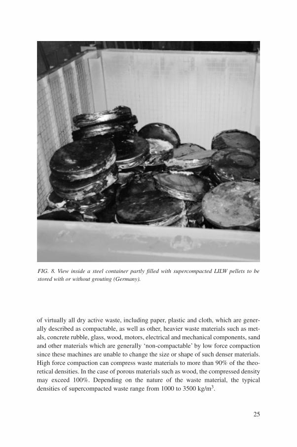
of virtually all dry active waste, including paper, plastic and cloth, which are gener-ally described as compactable, as well as other, heavier waste materials such as met-als, concrete rubble, glass, wood, motors, electrical and mechanical components, sandand other materials which are generally ‘non-compactable’ by low force compactionsince these machines are unable to change the size or shape of such denser materials.High force compaction can compress waste materials to more than 90% of the theo-retical densities. In the case of porous materials such as wood, the compressed densitymay exceed 100%. Depending on the nature of the waste material, the typicaldensities of supercompacted waste range from 1000 to 3500 kg/m3.
25
FIG. 8. View inside a steel container partly filled with supercompacted LILW pellets to bestored with or without grouting (Germany).

3.2.3. Melting
During the melting process most volatile radioisotopes evaporate and escapefrom the molten mass. Other radioisotopes concentrate in the floating slag layer,which then solidifies on top of the melt ingot. The ingot contains less radioactivitythan the original batch of scrap metal, so that a decontaminating effect has takenplace. Several variations of the melting process (induction/electroslag/plasma/microwave melting) are available for different materials. While some processes havebeen designed to process metals exclusively, others are more or less dedicated to inor-ganic materials such as incinerator ash. The main advantages of melting are:substantial volume reduction; the possibility of recycling originally contaminatedmetallic waste; and no need for further immobilization [9]. The disadvantages are: theneed for adequate gaseous effluent control and a secondary waste treatment system;generation of secondary wastes; and substantial energy consumption.
3.2.4. Evaporation of liquid waste
Evaporation is a proven method for the treatment of liquid radioactive waste,providing good volume reduction or concentration of liquid aqueous waste, highdecontamination and good concentration. The technique is well developed and itsadvantages and disadvantages are well understood. Radioactive waste evaporators aregenerally kept simple in design to reduce maintenance problems at the expense of lossin thermal efficiency. Some wastes do, however, require more complex design, andscraped film evaporators have been used for intractable low level wastes. The evapo-rator produces a clean condensate that can be discharged to the environment and aconcentrate that must be encapsulated in cement or other media for long term storage.The main disadvantages are high capital, energy and maintenance costs, but they givelarge volume reductions and excellent decontamination factors.
3.3. BRIEF OVERVIEW OF CONDITIONING PROCESSES
In the selection of immobilization and packaging processes, it is essential totake into account compatibility of the waste with the matrix and container materials,and compatibility of the container with the interim storage and/or disposal environ-ment.
Many immobilization matrices have been used, e.g. cements, polymers, poly-mer modified cements, bitumen and glass. Matrices must be evaluated for a numberof properties including physical, thermal and radiation stability and mechanical per-formance. While taking into account the actual immobilization process, considerationmust also be given to the storage and transport of the waste packages produced.
26

Objectives should be: to produce an essentially monolithic product suitable for longterm storage; to satisfy transport regulations; and not to foreclose options for final dis-posal.
Table I summarizes currently available immobilization technologies. Whetheror not spent fuel declared as waste will require some sort of encapsulation/immobi-lization for disposal depends on the waste acceptance requirements not yet set up inMember States.
3.3.1. Cementation
A variety of LILW are suitable for incorporation into cement matrices. Thecementation process is simple, flexible, reliable and cost effective. This was the firstsolidification method applied, and considerable experience exists for the process.There is a wide potential for using this process, and the cemented product has certaininherent properties, e.g. radiation resistance, compatibility with many types of envi-ronmental conditions, and good actinide retention. Special chemical resistant cementswith different additives are now being used, e.g. resistant sulphate cement and slagcement. Cement can also be used for the immobilization of waste contaminated withtransuranium elements [11]. Disadvantages are that the final product volume isincreased and it is not very suitable for immobilization of organic waste and wastewith high salt content. Cemented waste is usually accepted for storage, whereas itsacceptability for disposal finally depends on its characteristics and compatibility withthe properties of the intended disposal environment.
3.3.2. Bituminization
Bituminization is currently being applied for the immobilization of the wasteresulting from treatment of low and intermediate level liquid effluents [12]. Theprocess has been in use for more than 20 years. The bituminized product has a very
27
TABLE I. CURRENTLY AVAILABLE IMMOBILIZATION TECHNOLOGIESFOR RADIOACTIVE WASTE
Waste type Immobilization process
Short lived low and intermediate level Cementation, bituminization, polymerization
Long lived low and intermediate level Cementation, bituminization, vitrification
High level Vitrification
28
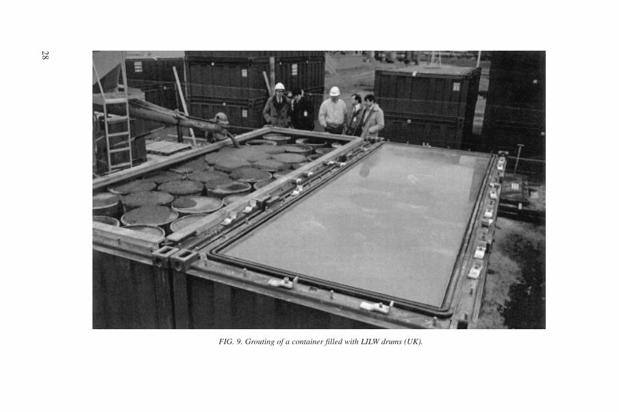
FIG. 9. Grouting of a container filled with LILW drums (UK).
29
low permeability and solubility in water and is compatible with most environmentalconditions. Some restrictions must, however, be exercised with regard to the incorpo-ration of strongly oxidizing components, e.g. nitrates, biodegradable materials andsoluble salts. Furthermore, questions may be raised concerning the long termphysicochemical and radiation stability of bitumen.
Bituminization is typically a process for the immobilization of very low heatgenerating wastes. Its use is restricted to materials with low alpha contamination(a < 40 TBq/m3 in liquid waste). During storage of bituminized waste, special carehas to be taken owing to its flammability.
3.3.3. Polymerization
Polymers have been developed for immobilization of LILW that includes incor-poration of evaporation concentrates, spent ion exchange resins, sludges and ashes[13]. Several types of polymer have been considered, including urea formaldehyde,polyethylene, styrene divinylbenzene (for evaporator concentrates), epoxy resins (forspent ion exchange resins), polyester, polyvinylchloride and polyurethane. The maindisadvantage of the polymerization processes is that radioactive water can only beincorporated in small amounts. Polymers in most cases are compatible with organicwastes and are also efficacious for the incorporation of soluble salts, e.g. nitrates andsulphates. The use of polymers is severely limited by their ability to withstand radia-tion doses.
As with bituminized waste, the additional fire hazard must be taken intoaccount when designing a storage facility for wastes incorporated in polymers.
3.3.4. Vitrification
At present the only process identified and applied for the immobilization ofHLW is vitrification. Liquid wastes are converted into a solidified form by addingsuitable glass forming materials and fusing these materials at a high temperature, typ-ically greater than 1000oC. Some specific vitrification processes are described inRef. [14].
3.4. EXAMPLES OF WASTE PACKAGES
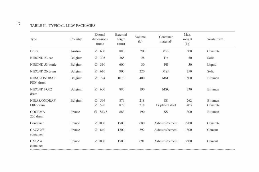
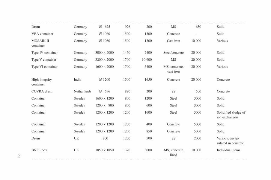
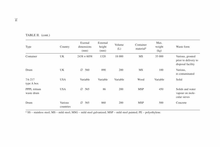
Examples of waste packages are shown in Figs 9 and 10. Tables II, III and IVpresent an overview of relevant industrial and radiological characteristics for sometypical LILW, HLW and spent fuel packages produced in Member States.

3030
FIG. 10. Cutaway of a shielded CASTOR cask made from cast iron for transport and storage of spent fuel. Fuel rods,double lid system, drillings for neutron absorber and heat dissipation vanes can be seen (Germany).
31
4. STORAGE FACILITIES
4.1. GENERAL CATEGORIES
Waste storage which has been used or is currently in use falls into three generalcategories: subsurface storage, area storage and engineered storage.
Subsurface storage consists basically of emplacement of waste packages inengineered shallow trenches, frequently featuring a solid base of asphalt or con-crete, with suitable backfilling material, in such a manner that retrieval is straight-forward.
Area storage, also known as open vault storage, consists in emplacement ofwaste packages on the ground or on a constructed base, either in the open air or witha simple open sided covering.
Engineered storage refers to any fully contained building or structure specifi-cally provided for the storage of waste packages. Engineered store designs are inmany cases based on the need to handle large volumes of drummed or boxed wastepackages with substantial surface dose rates. These stores may range from simplyconstructed enclosures to highly engineered facilities incorporating shieldingstructures and remote handling equipment, fully serviced with ventilation, effluentcollection and instrumented controls. Typical examples of such storage facilities arelisted in the Appendix.
4.2. STORAGE OF LOW CONTACT DOSE RATE LILW
LILW with low contact dose rates can usually be stored in any of the generalfacility categories described above.
4.2.1. Civil construction
4.2.1.1. Subsurface storage
Subsurface storage was commonly used in some Member States, notably theUSA, to store large amounts of transuranic wastes for periods longer than 20 years.The cost of retrieval of these wastes today, coupled with the risk involved, has demon-strated that this option is not a prudent one, especially for developing countries.
Subsurface storage should only be considered where storage time is very shortand climatic conditions favourable, such as in dry climates and locations remote frominhabited areas. In general, this type of storage is not recommended for future wastearisings unless appropriate environmental monitoring measures are taken.
32
TABLE II. TYPICAL LILW PACKAGES
Exernal ExternalVolume Container
Max.Type Country dimensions height
(L) materialaweight Waste form
(mm) (mm) (kg)
Drum Austria ∆ 600 880 200 MSP 500 Concrete
NIROND 23 can Belgium ∆ 305 365 28 Tin 50 Solid
NIROND 53 bottle Belgium ∆ 310 600 30 PE 50 Liquid
NIROND 26 drum Belgium ∆ 610 900 220 MSP 250 Solid
NIRAS/ONDRAF Belgium ∆ 774 1073 400 MSG 1500 BitumenFS04 drum
NIROND FC02 Belgium ∆ 600 880 190 MSG 330 Bitumendrum
NIRAS/ONDRAF Belgium ∆ 596 879 218 SS 262 BitumenFI02 drum ∆ 596 879 218 Cr plated steel 403 Concrete
COGEMA France ∆ 583.5 883 190 SS 300 Bitumen220 drum
Container France ∆ 1000 1500 680 Asbestos/cement 2200 Concrete
CACZ 2/3 France ∆ 840 1200 392 Asbestos/cement 1800 Cementcontainer
CACZ 4 France ∆ 1000 1500 691 Asbestos/cement 3500 Cementcontainer
33
Drum Germany ∆ 625 926 200 MS 650 Solid
VBA container Germany ∆ 1060 1500 1300 Concrete – Solid
MOSAIK II Germany ∆ 1060 1500 1300 Cast iron 10 000 Variouscontainer
Type IV container Germany 3000 × 2000 1450 7400 Steel/concrete 20 000 Solid
Type V container Germany 3200 × 2000 1700 10 900 MS 20 000 Solid
Type VI container Germany 1600 × 2000 1700 5400 MS, concrete, 20 000 Variouscast iron
High integrity India ∆ 1200 1500 1650 Concrete 20 000 Concretecontainer
COVRA drum Netherlands ∆ 596 880 200 SS 500 Concrete
Container Sweden 1600 × 1200 800 1200 Steel 3000 Solid
Container Sweden 1200 × 800 800 600 Steel 3000 Solid
Container Sweden 1200 × 1200 1200 1600 Steel 5000 Solidified sludge ofion exchangers
Container Sweden 1200 × 1200 1200 400 Concrete 5000 Solid
Container Sweden 1200 × 1200 1200 850 Concrete 5000 Solid
Drum UK 800 1200 500 SS 2000 Various, encap-sulated in concrete
BNFL box UK 1850 × 1850 1370 3000 MS, concrete 10 000 Individual itemslined
34
TABLE II. (cont.)
Exernal ExternalVolume Container
Max.Type Country dimensions height
(L) materialaweight Waste form
(mm) (mm) (kg)
Container UK 2438 × 6058 1320 18 000 MS 35 000 Various, groutedprior to delivery todisposal facility
Drum UK ∆ 560 890 200 MS 100 Various,a contaminated
7A-217 USA Variable Variable Variable Wood Variable Solidtype A box
PPPL tritium USA ∆ 565 86 200 MSP 450 Solids and waterwaste drum vapour on mole-
cular sieves
Drum Various ∆ 565 860 200 MSP 500 Concretecountries
a SS – stainless steel; MS – mild steel; MSG – mild steel galvanized; MSP – mild steel painted; PE – polyethylene.

35
FIG. 11. Area storage of waste drums.

4.2.1.2. Area storage
Area storage may be considered for various waste packages such as mild steeldrums with plastic liners containing pre-packed waste, ISO freight containers holdingdrums or pre-packaged items, and plastic drums. An example of area storage is givenin Fig. 11. Routine inspection of waste packages is in many cases a feature of suchstores.
Essential requirements for area storage would be absence of vegetation anddelineation of the storage area by appropriate fences to preclude unauthorized access.Potential exposure to the waste packages and the lack of climate control make thismethod of storage inadequate for mild steel containers or drums.
4.2.1.3. Engineered storage
An engineered storage facility for LILW with low contact dose rates may be ofsimple construction, for example an inflatable building on an asphalt base pad.Alternatively a warehouse type construction with no arrangements for packagehandling, heating or ventilation is widely used.
36
TABLE III. TYPICAL HLW PACKAGES
External ExternalVolume Container
Type Country diameter height(L) materiala
(mm) (mm)
Pamela 60 Belgium 298.5 1200 60 SScanister 298.5 1200 60 SS
Pamela 150 Belgium 430 1346 150 SScanister
COGEMA France 430 1338 150 SS150 canister
COGEMA France 1130 1707 1300 SS1425 drum
COGEMA France 1000 1500 676 ReinforcedCBFC2 concretecontainer
BNFL UK 420 1300 150 SScanister
a SS – stainless steel.

Recently, more sophisticated engineered stores with full engineered featureshave been constructed. The facilities may include arrangements for package handling,shielding with concrete (or equivalent), remote inspection, ventilation, temperaturecontrol, effluent collection, and prepared building surfaces to aid decontamination.
4.2.2. Package handling
Waste packages may be handled in the following ways:
(a) Manually (for small packages with very low surface dose rate);(b) With a lift truck (fork type for containers on pallets or clamp type for drums
(Fig. 12));(c) With a locally controlled overhead crane (with package hooks for containers or
clamps for steel drums);(d) With a remote controlled crane, sometimes computer assisted, with a tele-
scopic arm and monitored emplacement devices. Such cranes are used byBelgoprocess in Belgium for LILW (Fig. 13).
37
Max. Max. initial Max. initial HeatWaste
weight activity dose rate productionform
(kg) (GBq) (Sv/h) (W)
250 5.6E5 (b) 140 70 Glass510 3.3E5 (b) 7.5 40 Glass/lead
500 1.8E5 (b) 12 20 Glass
500 6.6E6 (137Cs) 1.4E4 4000 Glass4.6E6 (90Sr)
4500 6.3E4 (137Cs) – 115 Cemented5.2E4 (90Sr) cladding hulls
4000 3.15E3 (b/g) – – Concrete/0.63 (a) lead
550 4.5E7 4500 2500 Glass

TABLE IV. TYPICAL SPENT FUEL PACKAGES
External ExternalVolume Container
Type Country diameter height(L) materiala
(mm) (mm)
CASTOR IIa Germany 2050 6050 4080 DCI
CASTOR V/19 Germany 2440 5680 7150 DCI
a DCI – ductile cast iron.
4.2.3. Emplacement
Waste packages may be stacked or placed on shelves or in racks (Figs 14 and15). Shelf arrangements are usually suitable for storage of liquid waste in approvedsmall bottles. Free stacking is the most commonly used arrangement for containersand drums. Vertical stacking is usually limited by the load bearing capacities of thebottom-most containers as well as by drop height or seismic requirements.Alternatively, cylindrical packages may be stacked on their sides or grouped onstacked pallets.
4.2.4. Record keeping
On-line registration of waste package location and identity is not normallypractised for LILW packages with low contact dose rates unless a nuclear criticalitycontrol is required. Manual bookkeeping or entry into a computer database is gener-ally used.
4.3. STORAGE OF HIGH CONTACT DOSE RATE LILW
4.3.1. Civil construction
4.3.1.1. Subsurface storage
Subsurface storage facilities do exist (e.g. in caissons) but are not recommendedfor new arisings of LILW with high dose rates owing to difficulties of inspection andretrieval. An example of a storage facility for hulls and reactor components in Indiais shown in Fig. 16.
38
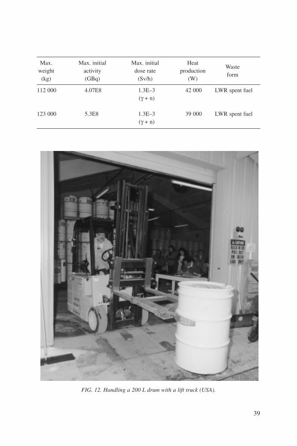
39
FIG. 12. Handling a 200 L drum with a lift truck (USA).
Max. Max. initial Max. initial HeatWaste
weight activity dose rate productionform
(kg) (GBq) (Sv/h) (W)
112 000 4.07E8 1.3E–3 42 000 LWR spent fuel(g + n)
123 000 5.3E8 1.3E–3 39 000 LWR spent fuel(g + n)

40
FIG. 13. Interim storage of LILW packages (Belgium).

41
FIG. 14. Emplacement of a 200 L drum in the rack (Belgium).

42
FIG. 15. Emplacement of drums in racks for stacking (Belgium).

43
Concrete bearing block Concrete cover plug
Mild steel pipe
Sand filling
Steel pipe
Brickwork
Plastering witha waterproofingcompound
Waterproofing
Plate
Angle frame
Concrete
FIG. 16. Subsurface storage facility for hulls and reactor components (India).

44
FIG. 17. Modern high contact dose rate LILW facility (UK).

4.3.1.2. Area storage
Area storage is suitable for waste packages placed inside approved individualshielded storage containers made from corrosion resistant materials. Area storagemay also be provided for waste placed in corrosion resistant containers in an openvault structure with a solid base but, in addition, shielding walls (earthen or concrete)up to the stack level are used to limit dose rates outside the store. Owing to their highdose rate, packages are often stored in high integrity containers that are suitable forboth area storage and transport.
4.3.1.3. Engineered storage
Engineered storage is the most commonly adopted practice for LILW with highsurface dose rates, particularly where large numbers of packages are produced. Theminimum standard of construction for these stores is a warehouse type building, fullycontained, with a solid floor, adequate safety provisions for package inspection andsufficient shielding.
New facilities would be expected to be of a higher standard, incorporatingequipment for package handling, a shielding provision inside the building civil struc-ture, design arrangements to prevent water in-leakage, ventilation, and temperaturecontrol. An example of a modern storage facility is shown in Fig. 17.
An example of a small storage facility for vitrified long lived, high contact doserate LILW is shown in Fig. 18. The waste arises from the decommissioning of anuclear power plant (NPP) with a demonstration heavy water gas cooled reactor. Thestorage facility, together with a vitrification plant, is located in the NPP building.
4.3.2. Package handling
Package handling may be undertaken with:
(a) A shielded lift truck and/or gantry cranes for drums or containers;(b) A remote controlled crane, using a remote controlled or automatic grab to
emplace the packages in stacks inside the storage vault;(c) A remote controlled trolley on which boxed wastes are stacked prior to
emplacement (Fig. 19).
4.3.3. Emplacement
Packages may be stacked inside a supporting structure or in self-supportingarrays where stability under potential seismic loadings is demonstrated in the design.Pre-stacked packages on remote controlled trolleys are emplaced directly inside the
45

vault (Fig. 20). Cylindrical packages may be stacked on their sides inside supportingstructures (Fig. 21).
Transport casks also approved for storage may be emplaced directly inside thestore, and are not usually stacked.
4.3.4. Record keeping
While manually recorded information is acceptable, most modern LILW storesfor packages with high contact dose rates include arrangements for on-line registra-tion of the package identity and storage location.
46
FIG. 18. Small storage facility for vitrified LILW (Slovakia).

47
FIG. 19. Stacked packages on a remote controlled trolley awaiting emplacement in the wastestore (UK).
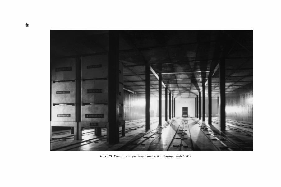
48
FIG. 20. Pre-stacked packages inside the storage vault (UK).
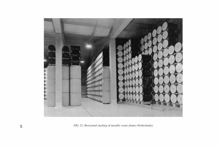
49 FIG. 21. Horizontal stacking of metallic waste drums (Netherlands).
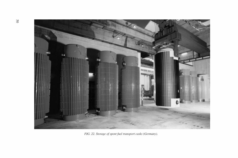
50
FIG. 22. Storage of spent fuel transport casks (Germany).

51
4.4. STORAGE OF VITRIFIED HLW AND SPENT FUEL
In some countries spent fuel is considered as waste. The comments below donot apply to spent fuel stored while awaiting reprocessing, which is the subject of sep-arate reports.
4.4.1. Civil construction
4.4.1.1. Subsurface storage
Non-engineered subsurface storage is not acceptable for vitrified HLW andspent fuel.
4.4.1.2. Area storage
Area storage is only acceptable for vitrified HLW and spent fuel if the waste iscontained in an accident-proof, self-cooling cask, providing appropriate shielding andguaranteed containment. Typically, the casks should be of the same standard as theapproved containers used for waste transport.
4.4.1.3. Engineered storage
Engineered storage is normally required for vitrified HLW and spent fuel. In itssimplest form this can involve storage of transport casks approved for storage withinengineered structures which include additional shielding provisions and are designedto remove heat convecting naturally from the cask. An example of this is the storageof spent fuel awaiting direct disposal in Germany (Fig. 22).
High level waste canisters are commonly stored in pits or channels within aconcrete vault. Cooling is achieved by natural convection or by forced ventilation.This is required in order to control the maximum temperature in the glass below thelimit set by the waste package requirements. Such vaults may be constructed belowground level to assist radiation shielding. An example of such a facility in India isshown in Fig. 23.
The engineered stores for vitrified HLW are fully equipped with remote devicesfor package handling and sufficient shielding provisions inside the building structurethat may lead to about 1.7 m or more of concrete (or equivalent). Stores are usuallydesigned on a modular basis to allow extension when required. An alternative methodof waste cooling may be provided by wet storage in water filled pools, with heatexchange facilities to remove heat from the circulating cooling water. At present, thistechnique is only used in the CLAB storage facility for spent fuel in Sweden (Fig. 24).

52
FIG. 23. Air-cooled storage facility for HLW (India).
Concrete slab
Waterproofing Sliding bearingInsulating lining
30 t crane
Inner vault
Pre-stressed beam
Stainlesssteel duct
Inlet duct forforced air supply
Ground level
Outer vault
Ground level
Fresh airsupply
Stack
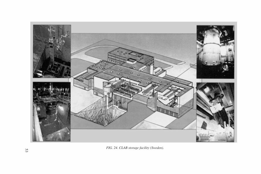
53 FIG. 24. CLAB storage facility (Sweden).

54
FIG. 25. Package handling of casked vitrified HLW using overhead crane (Germany).(1) container area; (2) airlock; (3) transport and storage container; (4) air inlet; (5) air outlet.
± 0.00
+ 10.50
+ 17.90
± 0.00
+ 10.50
+ 17.90
50 10
m
FIG. 26. Charging machine on top of the interim storage cell for vitrified HLW canisters(France).

55
4.4.2. Package handling
The casked vitrified HLW is normally handled by an overhead crane (Fig. 25).For the uncasked canisters with vitrified HLW, a remote controlled crane using ashielded grab (charging machine) emplaces the canisters into vertical stainless steelstorage channels fitted through a concrete store face (Fig. 26). Concrete plugs areused to shield the radiation from the canister while loading or on completion of load-ing. Moveable shielding gates can be used to minimize radiation exposure during theloading operations.
4.4.3. Emplacement
Vitrified waste canisters are emplaced inside the stainless steel channels, usu-ally in stacks up to 12 canisters high. A typical emplacement procedure is shown inFig. 27.
4.4.4. Record keeping
Record keeping arrangements are as described in Section 4.3.4 for LILW withhigh contact dose rates.
4.5. STORAGE OF SPENT SEALED RADIATION SOURCES
Spent radiation sources from industry or from medical applications such as60Co, 137Cs and 226Ra are stored for decay (short lived radionuclides) or for condi-tioning (long lived radionuclides). These sources can usually be stored in LILW stor-age facilities, either in area storage or, preferably, in engineered storage facilitiessimilar to those described in Section 4.3. Package handling and emplacement are asdescribed in Section 4.3.
5. OPERATIONAL EXPERIENCE ANDOPTIMAL STORAGE PRACTICES
Member States have acquired a significant amount of experience in construct-ing and operating all types of waste storage facility. Some States are in the process ofretrieval of waste from substandard storage conditions, e.g. temporary subsurfacestorage in trenches, and there have been many individual examples of failures of

56
FIG. 27. Transfer of vitrified HLW canisters to storage pit (Belgium).
Movement of charging machine (CM)CM and
containeron the pit
Transfer oflower plug
Loweringcontainer into
storage pit
Basket
Container
Pit
Removal of lowerplug
Placement ofshielding valve
with CM
Removal of upper plug
Lower plug
Upper plug
Pit
Preparation of a storage pit
STORAGE CELL
HANDLING HALL

57
FIG. 28. Examples of corrosive failures of waste packages.

waste packages. Failures may be caused, for example, by chemical reactiongenerating explosive atmospheres within the packages, internal and external corro-sion of the container, and galvanic reaction between stacked containers in a store.Figure 28 shows examples of corrosive failures.
The experience acquired by Member States demonstrates the importance andcollective significance of their knowledge of the behaviour of waste packages duringstorage. Recognition that deficiencies may exist in current and past storage arrange-ments is expected to lead to the selection of optimal storage practices that can berecommended for use by Member States. However, operation of well designed andwell constructed storage facilities for suitable waste packages has demonstrated thatvery few problems exist with stored waste packages.
5.1. OPERATIONAL CONTROL OF STORAGE CONDITIONS
To verify the predicted performance of a storage facility, on the basis of thesafety assessment and design criteria, a number of operational control measures mustbe applied. They may be applied systematically or randomly, or they may involvecontinuous monitoring. Control measures may be accomplished locally for contacthandled waste, or may be remote (e.g. cameras) in areas where personnel are notpermitted routine access.
Observations and measurements are necessary to ensure that the storage struc-ture remains in compliance with the original design specifications. In the case ofsubsurface or area storage without an engineered foundation, stability of the gradedsurface round the site must be controlled. Provisions for water run-off must be madeto prevent degradation of the area surface. In the case of an engineered structurewith an engineered foundation, regular inspections must be carried out to seewhether degradation or deformation of the structure (foundation, walls, roof) haveoccurred.
Section 2 of this report listed the most important parameters to be controlled bythe design of a storage facility. However, those of particular concern for operationsare (a) air temperature and humidity, and (b) water in-leakage by collection in pits orsumps.
The collected liquid should be analysed for the following chemical and radio-chemical parameters (as a minimum) to determine whether the liquid has arisenbecause of package failure or in-leakage of rainwater:
• pH,• alpha activity (by counting and spectrometry),• beta/gamma activity (by counting and spectrometry).
58

Corrective action would normally be necessary to seal leak paths or isolatefailed packages should these occur. Some additional parameters should also bechecked where appropriate:
• Air flow rate (air changes),• Control of negative pressure inside the facility (when applicable),• Outlet air control (filtration, sampling),• Presence of particulates, organics and radionuclides in the exhaust air.
Site specific measurements should reflect a graded approach that depends uponthe type of storage facility and the waste emplaced therein. For area storage (non-engineered), waste containers must provide complete confinement of the waste formand complete protection from environmental conditions which could damage or alterthe waste form. Environmental monitoring would be limited to air monitoring bymeans of a permanent grid where routine samples are taken on a regular basis.Routine samples to monitor radioactivity in groundwater and surface water shouldalso be taken and analysed to ensure that the waste packages in storage are not caus-ing contamination of the ground and surface water.
The engineered storage structure is designed to contain waste packages.Contamination inside a storage facility under normal operating conditions is notusually expected. If an accident occurs that results in a loss of containment of thewaste package, provisions for decontamination of the affected area of the storagefacility should be available. This applies to both remote handled and contact handledwastes.
Radiological control should be performed in order to protect operators in botharea and engineered storage facilities. In the case of an open air storage facility, thesurface dose rate and surface contamination should be measured on packages. Forpackages of greater activity the dose rate should be measured remotely in a way thatkeeps the exposure of the personnel as low as reasonably achievable. In engineeredstorage, the same objectives are appropriate, although contamination may be moni-tored by air sampling or representative measurement of waste packages.
In a storage building, a contact dose rate should be verified adjacent to the outerwall. The external dose rates outside the storage building should be regularly moni-tored to ensure that they conform to the national standard for unrestricted access tofacilities within a radiologically controlled area.
In cases when storage radiological conditions change (e.g. if stored packagesare more radioactive than previously expected), shielding may be added to the interiormain walls or to the waste package array.
Nuclear criticality control by fission neutron monitoring must be applied wherefissile material in high concentrations (e.g. spent fuel, plutonium bearing wastes) isstored.
59
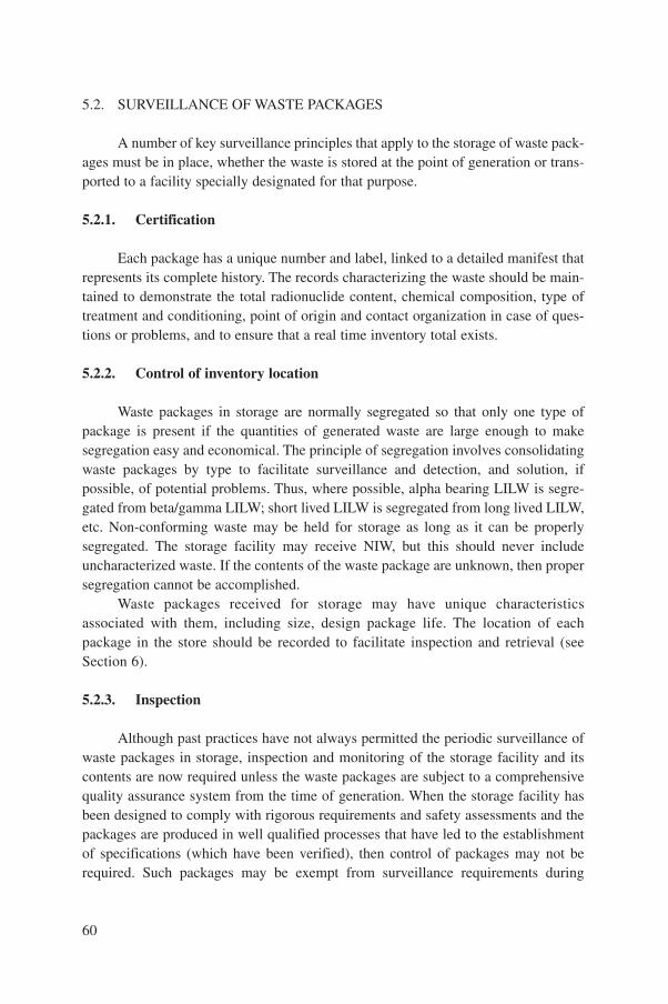
5.2. SURVEILLANCE OF WASTE PACKAGES
A number of key surveillance principles that apply to the storage of waste pack-ages must be in place, whether the waste is stored at the point of generation or trans-ported to a facility specially designated for that purpose.
5.2.1. Certification
Each package has a unique number and label, linked to a detailed manifest thatrepresents its complete history. The records characterizing the waste should be main-tained to demonstrate the total radionuclide content, chemical composition, type oftreatment and conditioning, point of origin and contact organization in case of ques-tions or problems, and to ensure that a real time inventory total exists.
5.2.2. Control of inventory location
Waste packages in storage are normally segregated so that only one type ofpackage is present if the quantities of generated waste are large enough to makesegregation easy and economical. The principle of segregation involves consolidatingwaste packages by type to facilitate surveillance and detection, and solution, ifpossible, of potential problems. Thus, where possible, alpha bearing LILW is segre-gated from beta/gamma LILW; short lived LILW is segregated from long lived LILW,etc. Non-conforming waste may be held for storage as long as it can be properlysegregated. The storage facility may receive NIW, but this should never includeuncharacterized waste. If the contents of the waste package are unknown, then propersegregation cannot be accomplished.
Waste packages received for storage may have unique characteristicsassociated with them, including size, design package life. The location of eachpackage in the store should be recorded to facilitate inspection and retrieval (seeSection 6).
5.2.3. Inspection
Although past practices have not always permitted the periodic surveillance ofwaste packages in storage, inspection and monitoring of the storage facility and itscontents are now required unless the waste packages are subject to a comprehensivequality assurance system from the time of generation. When the storage facility hasbeen designed to comply with rigorous requirements and safety assessments and thepackages are produced in well qualified processes that have led to the establishmentof specifications (which have been verified), then control of packages may not berequired. Such packages may be exempt from surveillance requirements during
60

storage. These considerations apply without difficulties to vitrified HLW and immo-bilized LILW.
Experience at numerous nuclear facilities has shown that a number of inspec-tions may be required during interim storage. This is especially true when interimstorage has evolved into prolonged storage where repositories have not becomeavailable in the time frame originally anticipated. Attributes that should bemonitored include the adequacy of identification and the physical condition of thecontainer. Such inspections may be performed remotely using optical aids(cameras, telescopes, etc.) in order to minimize personnel exposure. The adequacyof such remote inspection techniques should be demonstrated, particularly if theyare relied on as the sole means of detecting container degradation. Inspectiontechniques should also include visual inspection when it is possible. For wastepacked in a metal container, a visual inspection will demonstrate possible corro-sion. For waste packed in a concrete container, stains and spills on the concretemay indicate diffusion of waste content through the container. Visual inspectionalso serves as an indicator for problems with packages to be further revealed bytechnical means. Where high activity wastes are involved, required inspectionsmay be performed remotely by camera, together with air and liquid effluentmonitoring.
Other attributes of importance to be monitored include the operability of cool-ing equipment where heat generating wastes are stored, as well as the operability ofmonitoring instrumentation.
The temperature of the waste package should be periodically monitored wherethermal power of waste forms is sufficient to initiate accidents if active cooling sys-tems fail in the absence of possible natural cooling. Also, where liquids are utilizedfor either cooling or shielding, periodic inspection of liquid levels should be per-formed. The frequency of such inspections should be derived from storage facilitysafety analyses but may require modification (increase in frequency) as facilities ageor as dictated by operational experience.
Mechanisms should be established to ensure that corrective action is taken forany deterioration of packages, package identification or cooling/monitoring systemsidentified during inspections.
The detection of general package degradation may be feasible by means ofsample inspection. Consequently, such packages containing the same matrix may berandomly selected for testing their integrity. Obviously, it is necessary to check anychange in surface dose rate of the package in order to know the geometric distribu-tions of activity. If abnormal increases in dose rate are detected locally, this means thepartitioning of activity is no longer homogeneous and, in that case, repackaging isprobably necessary. During this process and all inspection activities, operators shouldbe protected from excessive exposure to waste packages, in particular when poten-tially failed packages are involved.
61

5.3. EXAMPLES OF WASTE PACKAGE DETERIORATION DURINGSTORAGE
Past experience has revealed deterioration of some waste packages after a cer-tain period of storage. In recent years, the possible mechanisms of package degrada-tion have been well explored and are sufficiently known to be minimized orcompletely avoided by qualified conditioning and proper design of the waste storagefacility. The examples of deterioration of waste packages and the possible mecha-nisms of deterioration described below are not exhaustive but they illustrate the impor-tance of quality of waste packages and storage conditions to ensure safe storage.
5.3.1. Waste containers
Failure of waste packages during interim storage may occur owing to hiddendefects in the waste container manufacture, or unknown mechanisms of the interactionof the waste container with the waste form, i.e. failures within the quality assuranceprogramme. In practice, these undetected defects may cause deformation of the wastepackage during handling, loading, storage and retrieval. Container defects tend to man-ifest themselves early, and this is a good reason to segregate waste by the date of con-ditioning. In this way, systematic problems with container integrity can be avoided.
5.3.2. Gas generation
Any radioactive waste type, but especially alpha bearing waste, waste contain-ing hydrocarbons, and biological waste that has not been adequately treated, will gen-erate gases. In some cases these gases are flammable (e.g. hydrogen) and may posethe risk of fire or explosion. At the least, they will pressurize the waste package andcould deform it, making the package unacceptable for interim storage. To prevent thisoccurrence with wastes that generate hydrogen, vent devices can be installed on thedrum which automatically vent gases in one direction when a certain pressure isexceeded. When penetration of the package, needed to install this device, is not per-mitted or not advisable, hydrogen recombiners can be inserted in the waste matrix toprevent gas formation. In other cases non-airtight cover lids are applied on the wastedrums (Eurostorage at the Belgoprocess site) to prevent overpressure in those pack-ages. In this case, the storage area should have a moderate ventilation system to avoidaccumulation of hydrogen.
5.3.3. Physical and chemical changes
Some waste forms, although immobilized to meet waste acceptance criteria,change their properties in the container over time for a variety of reasons, including
62
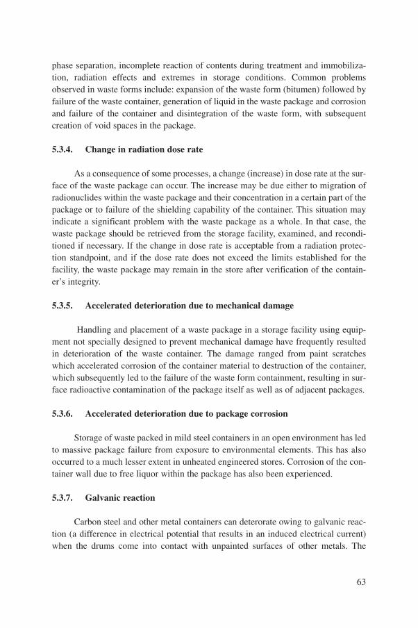
phase separation, incomplete reaction of contents during treatment and immobiliza-tion, radiation effects and extremes in storage conditions. Common problemsobserved in waste forms include: expansion of the waste form (bitumen) followed byfailure of the waste container, generation of liquid in the waste package and corrosionand failure of the container and disintegration of the waste form, with subsequentcreation of void spaces in the package.
5.3.4. Change in radiation dose rate
As a consequence of some processes, a change (increase) in dose rate at the sur-face of the waste package can occur. The increase may be due either to migration ofradionuclides within the waste package and their concentration in a certain part of thepackage or to failure of the shielding capability of the container. This situation mayindicate a significant problem with the waste package as a whole. In that case, thewaste package should be retrieved from the storage facility, examined, and recondi-tioned if necessary. If the change in dose rate is acceptable from a radiation protec-tion standpoint, and if the dose rate does not exceed the limits established for thefacility, the waste package may remain in the store after verification of the contain-er’s integrity.
5.3.5. Accelerated deterioration due to mechanical damage
Handling and placement of a waste package in a storage facility using equip-ment not specially designed to prevent mechanical damage have frequently resultedin deterioration of the waste container. The damage ranged from paint scratcheswhich accelerated corrosion of the container material to destruction of the container,which subsequently led to the failure of the waste form containment, resulting in sur-face radioactive contamination of the package itself as well as of adjacent packages.
5.3.6. Accelerated deterioration due to package corrosion
Storage of waste packed in mild steel containers in an open environment has ledto massive package failure from exposure to environmental elements. This has alsooccurred to a much lesser extent in unheated engineered stores. Corrosion of the con-tainer wall due to free liquor within the package has also been experienced.
5.3.7. Galvanic reaction
Carbon steel and other metal containers can deterorate owing to galvanic reac-tion (a difference in electrical potential that results in an induced electrical current)when the drums come into contact with unpainted surfaces of other metals. The
63

longer the waste is stored, internal or external influences can make package failuremore likely. After a certain time, however, the probability of package failure for mosttypes of waste becomes limited to external factors only.
5.4. STORAGE FACILITIES IN SELECTED MEMBER STATES
The Appendix provides a list of current, worldwide storage facilities, aspresented at the Technical Committee Meeting in Vienna in September 1996. Variousstorage facilities associated with private sector industry, e.g. nuclear power plants, arelocated throughout the USA, and are too numerous to mention in this report.
6. WASTE PACKAGE MANAGEMENT OPTIONS AFTERTHE LICENSED STORAGE PERIOD
6.1. GENERAL MANAGEMENT OPTIONS
The storage period of a waste package depends on many factors: the licensingperiod of the facility, the physical integrity of the package, economic considerations,and the availability of a disposal facility (either near surface or deep geological) or areconditioning facility.
After termination of interim storage, there are several possibilities for wastepackage management. In the most common situation, the packages will be retrievedfrom storage for transport to the disposal facility. To be accepted in the disposal facil-ity they will need a certification file. In order to establish this file and to demonstratethe acceptability of a package for transport and disposal, inspections must be per-formed by non-destructive methods as far as possible. In the case of a damaged pack-age, both non-destructive and destructive methods may be used during inspection.The damage will be corrected and the package will eventually be reconditioned inorder to be accepted in the final repository.
In other cases, the packages retrieved from the storage facility may be recondi-tioned in order to comply with transport regulations and waste disposal acceptancerequirements (e.g. non-immobilized wastes). Special precautions, including use of anoverpack, should be taken to ensure safety during transport to the reconditioningfacility if the facility is away from the store.
Finally, waste packages may be retrieved after a decay period when they havebecome very low level waste or cleared waste. In a few countries, clearance levelshave been defined to allow consideration of the packages as cleared waste [15].
64

In some cases, the non-availability of a disposal facility or the optimization ofwaste management may lead to prolonged storage of waste packages. When a storagefacility is adapted to several different types of package, this will often result in anextension of the licence of the facility. To obtain authorization for prolonged storageof packages, a new safety assessment may have to be made. To this end, a certainnumber of packages must be inspected in order to verify their integrity during theprevious period of storage and to validate facility performance. A failed package hasto be reconditioned properly for further safe storage. Methods of verifying wastepackage contents, container integrity, package stability, and suitability for disposalunder the various conditions and cases in which waste can be retrieved are discussedbelow.
6.2. SURVEY, INSPECTION AND TESTING
6.2.1. Necessity for survey, inspection and testing
The waste packages retrieved from the interim storage facility for disposal mustcomply with the specified waste disposal acceptance criteria. These are derived froma detailed safety assessment for both the store and the two phases of the repository(operational and post-operational) as introduced in Section 2.2. A typical set of prop-erties of the waste packages which may be quantitatively fixed by WAC for disposalis described in detail in Ref. [16]. These properties are to be controlled by an inspec-tion and testing programme, described below.
The survey, inspection and testing programme must be specifically tailored tothose packages retrieved from the storage facility whose integrity is unknown or sus-pect. For example, where 200 L drums (and other packages) have been stored inexcess of 20 years, special provisions should be made to ensure physical and radio-logical protection of personnel prior to excavation of these packages from unmoni-tored subsurface storage, because the integrity of these waste packages is unknown.A reliable system of safe retrieval can only be developed in such a case after carefulplanning and the initiation of a retrieval programme.
Where survey, inspection and testing of conditioned packages retrieved fromstorage whose characteristics are known and documented are involved, even if thewaste packages are surveyed during storage, degraded packages may remain unde-tected until retrieval. However, the implementation of a proper quality assurance pro-gramme during conditioning and storage should lead to a very low probability ofwaste package failure. In this case the presence of a failed package will be consideredextremely unlikely. Therefore efforts should be made to apply the ‘first in – first out’principle, and initial radiological surveys should be carried out to detect failed wastepackages and other situations that increase the risk to personnel safety.
65

6.2.2. Records review and survey of packages
The inspections normally begin with the review of the waste package recordsmaintained by the storage facility. The waste package records need to be retrieved andreviewed to determine the age of the package, length of time in storage, waste form,container type, unique retrieval requirements and potential package problems. Wastepackage quality control can be performed by examination of the waste package doc-umentation, which describes the relevant properties of the waste package, and by non-destructive or destructive testing of the waste package itself, when necessary. Thedecision on which of these procedures would be most suitable for package retrieval isinfluenced by questions like:
• How complete is the documentation?• How reliable is the documentation?• What is the presumed risk potential of the waste package failure?• What is the obvious state of the waste package?
Quality control by examination of the documentation is simplified when thewaste packages to be inspected have been conditioned by a qualified process.
In some Member States, thousands of 200 L drums with operational LLW fromnuclear power plants have been checked since 1990 before being disposed of in finalrepositories. Only a small number were controlled by testing waste packages, whilethe greater part were controlled by examination of the documentation. As a result,some packages required certain additional conditioning (see Section 6.3.2) prior todisposal, and only a very few were completely withdrawn. The implementation ofquality assurance procedures and development of conditioning technologies normallylead to reducing the proportion of failed packages to nearly zero.
When investigation of the records is complete, an initial survey should be per-formed. It may include a radiological survey to ascertain whether any risk exists fromfailed waste packages and visual survey of the waste packages prior to immediate retrievalin order to look for signs of pressurization, corrosion, catastrophic package failure andother conditions detrimental to acceptance for further interim storage or final disposal.
The conditions necessary to certify the retrieved packages for further interimstorage or disposal should then be defined. These conditions may range from none torepackaging or complete reconditioning, depending on the status of the package andthe length of interim storage. Packages that meet the criteria set for the records search,the initial survey, and the visual inspection may be subject to testing to determinewhether the WAC of the continued interim storage or the disposal facility have beenmaintained over the storage life of the package. Whether or not, and to what extentwaste packages must be further tested, has to be decided taking into account the con-tent of the records and the state of the packages.
66

It should also be noted that testing of waste packages is inevitably combinedwith a dose commitment to personnel. According to the ALARA principle, testing ofwaste packages must be balanced against the additional knowledge benefit to begained and must be minimized to a reasonable level.
Testing of the packages may be destructive or non-destructive. If testing isneeded, non-destructive rather than destructive tests should be implemented when-ever appropriate. Destructive examination of packages is usually limited to a smallfraction of the total waste packages retrieved, unless sampling shows that widespreaddegradation is present. In that case entire lots of waste packages may be identified forrepackaging. Non-destructive testing can ascertain many other waste package char-acteristics, and is performed on a larger number of packages received for disposalowing to its non-invasive nature. Non-destructive and destructive testing methods forwaste forms and packages are described in detail in Ref. [16].
6.2.3. Non-destructive testing methods
Non-destructive methods for testing waste packages include all tests that can beconducted without penetrating or opening the waste container. Various techniqueshave been developed and implemented in Member States, for example:
• Intensive visual inspection to detect corrosion, mechanical damage, penetra-tions and internal overpressure;
• Weighing to identify heavy parts, e.g. shielding material;• Dose rate measurements;• Radiography to determine contents of packages, void spaces, container wall
thickness, presence of liquids, etc.;• Scanning to measure the spacial distribution of gamma radiation and identify
prominent gamma emitters;• Tomography (with an external gamma source or with an accelerator) to detect
any inhomogeneity in density;• Passive and active neutron counting to detect fissile material.
Some of these tests are related to the package integrity control; others giveinformation on the content of the waste package and its distribution. Figure 29 showsa scanner to identify gamma emitting radionuclides in 200 L drums.
In general, non-destructive methods have proved helpful in identifying irregu-lar contents of radioactive waste packages. For major inhomogeneities, however, theymay provide qualitative rather than quantitative results. Moreover, alpha emittingnuclides and small amounts of low energy radiation may not be detected. In suchcases, destructive methods can supply additional information.
67
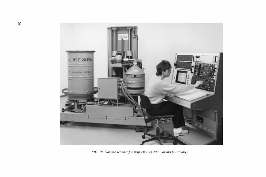
68
FIG. 29. Gamma scanner for inspection of 200 L drums (Germany).

6.2.4. Destructive testing methods
Destructive methods generally imply taking samples out of the waste packages.Several techniques for sampling LILW packages have been developed and partiallyimplemented in Member States. Sampling of HLW glass is not practised; it is notrecommended because of the high activity of the glass, difficulties in sampling andhigh dose commitment.
Gas samples can be taken by means of a hypodermic needle through the flexiblegasket of the waste package, or by a sealed puncture technique through the canisterwall. The samples may be analysed for radioactive (e.g. 14C, 85Kr, 129I) and non-radioactive (e.g. hydrogen, hydrocarbons) gases.
Solid samples can be taken by drilling through the container wall or directlyinto the waste form when the container has been opened. Normal drilling techniqueswill provide dust that can be analysed, whereas core drilling techniques will provideadditional information about the spatial distribution of waste constituents. In the caseof a drilling box for taking samples from a 200 L low level waste package, the drillingcompartment is ventilated and the exhaust air filtered and checked for radioactivity.
Destructive examination of contents of the waste packages could be done viatotal separation of the waste form from the container. Void spaces can be checked aswell as physical form and the presence of prohibited materials in the waste. It candetermine the existence of pyrophorics, water, explosives and other compounds thatprohibit emplacement at the disposal site. Samples may also be analysed to identifyradionuclides in the waste packages and to establish that the total activity is withinthe limits of certification.
Mechanical strength of the waste packages may also be checked by crushing.The tested packages in this case require overpacking prior to disposal.
6.3. ACTIONS REQUIRED AFTER THE LICENSED STORAGE PERIOD
6.3.1. Certification for transport and disposal
After retrieval and inspection of the waste package properties relevant to finaldisposal by either examination of records and documents or testing, it must be deter-mined whether the waste package meets the transport regulations and waste disposalacceptance criteria. Conformity of the waste package with transport regulations anddisposal acceptance criteria has to be certified by the transport authority and reposi-tory operators, respectively, or by independent experts authorized by the regulatoryauthorities, or by the legal authorities themselves. The transport organization and theoperator of the repository will accept certified waste packages only.
69

It is essential that non-immobilized waste retrieved from a storage facility issubject to the certification process because such waste must be conditioned andrepacked for transport and disposal. The objective is to meet the transport regulationsand WAC of the disposal facility. The original waste container may be reused, or itmay be crushed and placed with others in an overpack. As the waste undergoes thevarious processes necessary for certification (summarized in Section 2), a certifica-tion document should be developed which follows the waste to its completion as awaste package. A suitable identifier should be provided as required, and the packageshould be either sent to the disposal facility or returned to the storage facility as a cer-tified waste package.
Characterized and/or conditioned waste generally requires less effort to certify,and involves a lower risk to the operational staff. The possibility of encountering afailed or non-conforming waste package increases with the length of time the pack-age has been in storage. The certification process is usually well under way, and cer-tification for disposal usually involves verification of the transport and disposal WACagainst the package condition. Safety assessment takes into account the quality ofmaterials, the quality of the manufacturing process and the length of storage time toestimate the potential of failure or non-conformity of a waste package. If the durationof storage overpasses the licensed period, it may be recommended to reassess thispotential for failure.
So far, the experience of certification of LILW for disposal exists mainly incountries that are operating near surface repositories. The waste packages have beendesigned to comply with the WAC of the existing disposal facility, and obviously theyare expected to comply with them during and after the storage period. No worldwideexperience exists yet for HLW, but safety assessments of deep geological repositoriesare being made.
6.3.2. Reconditioning of waste packages
Reconditioning may also be necessary for non-conforming packages, except forthose containing non-immobilized waste that is retrieved specifically for recondition-ing.
Waste packages may be identified as non-conforming with regard to disposalWAC for several reasons, including incomplete documentation or inadequate infor-mation. More complicated problems related to conditioning may also exist, and theseproblems include: corrosion or mechanically induced damage, gas release, content offree liquids, presence of void spaces, excessive surface dose or radionuclide content.It is important that the record file for non-conforming waste packages is well docu-mented and correctly updated. Excessive amounts of non-conforming waste packagesshould be avoided; their number should stay within the statistical confidence level solong as a proper quality assurance programme has been established and implemented,
70

and provided that the waste packages are produced in accordance with the waste spec-ifications.
Damaged waste packages may be identified during routine store inspections orat a final retrieval stage. Failure of the waste container due to mechanical damage maybe major or minor in nature. Minor dents, scratches, rust or corrosion that are theresult of external impacts or other influences may be repaired so long as the packageintegrity has not been compromised. Major package failures or deformation due toexternal forces would require reconditioning or use of an overpack.
Failure or non-conformance of the waste form is a larger problem. Shouldinspection reveal that liquid has been generated in the waste package, or that organ-ics are present, the preferred option from the standpoint of cost and the ALARArinciple is in situ package remediation. A number of techniques are available to drainfluids through container penetration, e.g. by adding flocculants, absorbents andanticorrosive agents, or simply filling void spaces. Drum venting devices or gasrecombiners can also be installed to avoid gas generation problems. Corrosioninduced gas production may also be reduced by drying opened waste packages. If thepackage is deformed from the effects of gas pressurization, or if chemical changes inthe package have damaged the waste container, then repackaging or overpacking willbe necessary to meet the ongoing storage, transport or disposal waste acceptancerequirements.
Corrective action on retrieved non-conforming waste packages might lead to adeviating package dimension and form, caused by overpacking. It might even lead toa change in waste category. In such cases several measures have been developed andimplemented in some Member States that will convert such waste packages into aform suitable for final disposal. In Germany, for example, open waste packages aredried in order to reduce the free liquid content as well as the speed of corrosion. Theproduction of hydrogen from corrosion will also be minimized. Figure 30 shows, asan example, the PETRA facility for drying humid packages containing supercom-pacted waste with a capacity of 1000 drums per year.
Overpacks may mitigate problems in connection with mechanical or corrosioninduced effects. In addition, the surface dose levels may be reduced to acceptablelevels. Various types of overpack are currently in use. As an example, 200 L drumscontaining LILW can be inserted into either 400 L drums or a large rectangularcontainer manufactured of steel or reinforced concrete. The open space in theseoverpacks may be grouted with cement to increase the mechanical and shieldingproperties.
6.3.3. Retrieval for disposal as very low radioactive waste or cleared waste
Long term storage may allow some low activity or short lived waste packagesto decay below clearance levels established by regulatory authorities. In this case
71
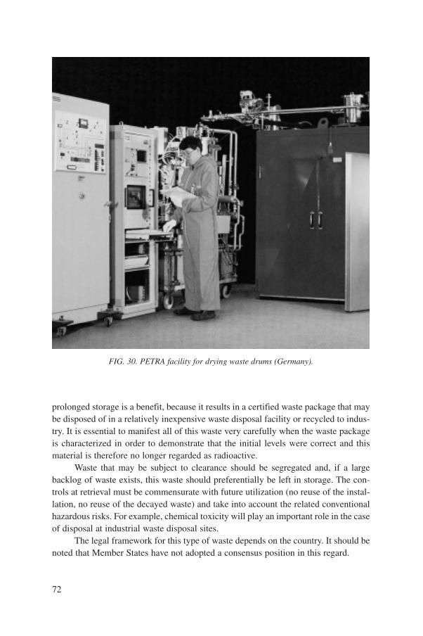
prolonged storage is a benefit, because it results in a certified waste package that maybe disposed of in a relatively inexpensive waste disposal facility or recycled to indus-try. It is essential to manifest all of this waste very carefully when the waste packageis characterized in order to demonstrate that the initial levels were correct and thismaterial is therefore no longer regarded as radioactive.
Waste that may be subject to clearance should be segregated and, if a largebacklog of waste exists, this waste should preferentially be left in storage. The con-trols at retrieval must be commensurate with future utilization (no reuse of the instal-lation, no reuse of the decayed waste) and take into account the related conventionalhazardous risks. For example, chemical toxicity will play an important role in the caseof disposal at industrial waste disposal sites.
The legal framework for this type of waste depends on the country. It should benoted that Member States have not adopted a consensus position in this regard.
72
FIG. 30. PETRA facility for drying waste drums (Germany).

6.3.4. Prolonged storage
It may happen that waste packages cannot be brought into conformity with theWAC of a certain repository, or that a repository is not yet available at the time whenthe design life of the interim storage facility runs out or the storage licence expires.For these or some other reasons the need for prolonged storage may arise.
In general, prolonged storage may be considered as storage of waste in a facil-ity beyond the time originally planned by the design and licence. For LILW, at leasta ten year period has been recommended in the design capacity of storage facilities indeveloping countries without current disposal capacity [17, 18]. Of course, theabsolute capacity of the storage facility that will hold ten years’ worth of waste willvary among Member States. In addition, the design life of this storage facility willusually greatly exceed ten years (30 to 50 years is typical). A period exceeding tenyears was considered appropriate for a waste package because it was established thatproblems with the packages would begin to manifest themselves within that period oftime, and special provisions for continued storage of the waste would be required.This may, however, not be appropriate for waste packages designed and licensed forlong term storage, e.g. heavy shielded casks for HLW and spent fuel storage. It mayalso not be appropriate for packages in modern stores, conditioned to rigorous stan-dards under a quality assurance programme.
To authorize prolonged storage, a new safety assessment of the storage facility isnecessary. Packages should undergo representative sampling, and if all the packages arenot accessible, restacking must be assessed. Packages must be inspected to a certainextent, first by visual inspection, and then by some other testing methods if necessary.
It is recognized that Member States with a large backlog of waste in prolongedstorage will commit significant resources to comply with this requirement. However,Member States with small quantities of conditioned waste may benefit from pro-longed storage, especially when the construction of a disposal facility has beendelayed to the distant future.
7. RECOMMENDED MEASURES TO ENSUREOPTIMAL PERFORMANCE OF WASTE PACKAGES
DURING STORAGE
A series of measures to ensure optimal package performance under conditionsof storage has been developed and should serve as recommendations to MemberStates, with explanation of their applicability. The need to establish waste acceptancecriteria for storage, transport and disposal, and to comply with them at the point ofwaste generation, results in the practices described below. The implementation of
73
such practices and qualification of the conditioning process will result in a packagereadily acceptable for storage, transport and disposal.
7.1. WASTE GENERATION AND CHARACTERIZATION
(a) Generated waste should be segregated as far as possible to facilitate subsequenttreatment and conditioning in order to to reduce waste toxicity, mobility andvolume. Member States should take into account their present and plannednational waste management systems in the generation of radioactive waste. Ifno disposal facility is available in the foreseeable future, the storage period ofwaste packages will probably have to be prolonged, and provisions for this sit-uation must be planned well in advance.
(b) Waste characterization and implementation of an adequate quality assuranceprogramme should begin at the point of waste generation by establishing a filecontaining detailed information on the waste.
7.2. STORAGE FACILITIES
(a) It is recommended that interim storage facilities should not accept any newwaste that is not adequately characterized. Every package must comply with theacceptance requirements of the storage facility.
(b) Non-immobilized wastes emplaced in containers for storage should be segre-gated in the storage facility to the extent practical. The packages should also besegregated by waste type and storage duration.
(c) Facilities for the storage of waste should have a design life that is independentof the emplaced packages. The safety assessment should support the suitabilityof the facility for the duration of its intended use.
(d) Storage of low contact dose rate LILW should allow for visual inspection ofpackages. For prolonged storage it should be recognized that surveillancerequirements may need to be modified during the period of storage. For thestorage of high contact dose rate LILW, HLW and spent fuel, indirect controlsmay be put in place to inform the operators in the event of a failure.
(e) If the waste is characterized and conditioned properly within an adequate qual-ity assurance programme, failure of the package is not expected. But in theevent of package failure, for any reason, provisions for retrieval of a packagemust exist in the storage facility.
(f) Packages might be damaged if they fall during handling in a storage facility,and in that case the storage facility must provide for retrieval of the package aswell as decontamination of the area, if necessary. If a package failure occurs
74

during storage owing to the waste form or a widespread external corrosion of thecontainer, then further action to eliminate the hazard for all packages of the sametype should be evaluated. Packages that fail during storage and cannot be retrievedand remediated should be isolated in place, whenever possible, to protect person-nel, the environment and neighbouring waste packages from contamination.
7.3. PROVISION FOR RETRIEVAL OF WASTE PACKAGES
(a) Waste retrieval should be carefully planned and, as far as practical, preceded bya detailed survey and inspection of the waste packages to be retrieved. Retrievalactivities should follow a careful review of the manifest of all waste in storage.The sequence of retrieval of waste packages should take safety aspects intoaccount, including the condition of the packages. It is recommended that insome cases high dose rate or other hazardous waste be given priority for atten-tion. Each package in the interim storage facility should be registered and allrecords kept up to date.
(b) Conditioning of retrieved waste in order to correct package problems shouldfocus on cost effective remedies for non-conforming packages. In situ remedi-ation of these packages should be given priority. Packages with serious con-tainer structural problems must always be overpacked.
8. CONCLUSIONS
Both conditioning and storage of radioactive waste are fundamental steps in theradioactive waste management process to ensure protection of the population and theenvironment. If the safety principles and recommendations presented in this reportare applied, then the interim storage of packages can be considered safe. The expectedevolution of the packages is limited to the decrease of activity and thermal power.
Throughout the process of storage the recommended measures, taken together,demonstrate ALARA principles and involve the lowest life cycle cost. However, theydemand rigorous planning on the part of the national organizations charged withimplementing the waste management system. Decisions regarding waste storageshould not be deferred as part of the larger issue of waste management. If interimstorage is selected in favour of disposal by design or default, the same level offorethought and planning must drive the storage facility as if it were to be a facilityfor final disposal of waste. Equally, where justified on safety grounds, on-sitemanagement of radioactive waste should not be unduly constrained by the possiblerequirements for final disposal.
75
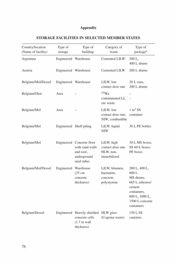
76
Appendix
STORAGE FACILITIES IN SELECTED MEMBER STATES
Country/location Type of Type of Category of Type of(Name of facility) storage building waste packagea
Argentina Engineered Warehouse Cemented LILW 200 L,400 L drums
Austria Engineered Warehouse Cemented LILW 200 L drums
Belgium/Mol/Dessel Engineered Warehouse LILW, low 28 L cans,contact dose rate 200 L drums
Belgium/Olen Area – 226Ra –contaminated LL –ore waste
Belgium/Mol Area – LILW, low 1 m3 SScontact dose rate, containerNIW, combustible
Belgium/Mol Engineered Shelf piling LILW, liquid 30 L PE bottlesNIW
Belgium/Mol Engineered Concrete floor LILW, high 30 L MS boxes,with sand walls contact dose rate. SS 60 L boxes,and roof, HLW, non- PE boxesunderground immobilizedsteel tubes
Belgium/Mol/Dessel Engineered Warehouse LILW, bitumen, 200 L, 400 L,(25 cm haematite, 600 Lconcrete concrete, MS drums,thickness) polystyrene 665 L asbestos/
cementcontainers,600 L, 1000 L,1500 L concretecontainers
Belgium/Dessel Engineered Heavily shielded HLW glass 150 L SSconcrete cells (Cogema waste) canisters(1.7 m wallthickness)
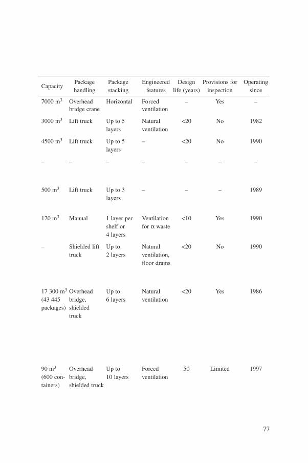
77
Package Package Engineered Design Provisions for OperatingCapacity
handling stacking features life (years) inspection since
7000 m3 Overhead Horizontal Forced – Yes –bridge crane ventilation
3000 m3 Lift truck Up to 5 Natural <20 No 1982layers ventilation
4500 m3 Lift truck Up to 5 – <20 No 1990layers
– – – – – – –
500 m3 Lift truck Up to 3 – – – 1989layers
120 m3 Manual 1 layer per Ventilation <10 Yes 1990shelf or for a waste4 layers
– Shielded lift Up to Natural <20 No 1990truck 2 layers ventilation,
floor drains
17 300 m3 Overhead Up to Natural <20 Yes 1986(43 445 bridge, 6 layers ventilationpackages) shielded
truck
90 m3 Overhead Up to Forced 50 Limited 1997(600 con- bridge, 10 layers ventilationtainers) shielded truck
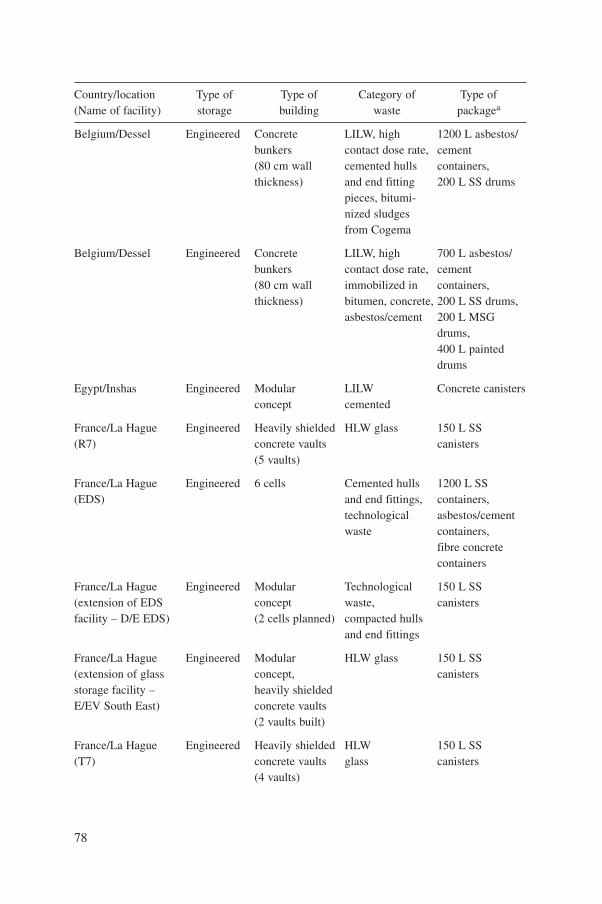
78
Country/location Type of Type of Category of Type of(Name of facility) storage building waste packagea
Belgium/Dessel Engineered Concrete LILW, high 1200 L asbestos/bunkers contact dose rate, cement(80 cm wall cemented hulls containers,thickness) and end fitting 200 L SS drums
pieces, bitumi-nized sludgesfrom Cogema
Belgium/Dessel Engineered Concrete LILW, high 700 L asbestos/bunkers contact dose rate, cement(80 cm wall immobilized in containers,thickness) bitumen, concrete, 200 L SS drums,
asbestos/cement 200 L MSGdrums,400 L painteddrums
Egypt/Inshas Engineered Modular LILW Concrete canistersconcept cemented
France/La Hague Engineered Heavily shielded HLW glass 150 L SS (R7) concrete vaults canisters
(5 vaults)
France/La Hague Engineered 6 cells Cemented hulls 1200 L SS(EDS) and end fittings, containers,
technological asbestos/cementwaste containers,
fibre concretecontainers
France/La Hague Engineered Modular Technological 150 L SS(extension of EDS concept waste, canistersfacility – D/E EDS) (2 cells planned) compacted hulls
and end fittings
France/La Hague Engineered Modular HLW glass 150 L SS(extension of glass concept, canistersstorage facility – heavily shieldedE/EV South East) concrete vaults
(2 vaults built)
France/La Hague Engineered Heavily shielded HLW 150 L SS(T7) concrete vaults glass canisters
(4 vaults)

79
Package Package Engineered Design Provisions for OperatingCapacity
handling stacking features life (years) inspection since
732 m3 Overhead Up to Forced <50 Limited 1997(270 con- bridge, 4 layers ventilationtainers remote and 2042 operateddrums) trolley
4556 m3 Overhead Up to Forced <50 Limited 1978(18 393 bridge, 4 layers ventilation,drums) remote filtration of
operated exhausted air,trolley water control
in pits
– Overhead 2 layers Natural >30 Available 1997bridge crane ventilation
4500 Loading/ 9 canisters Forced <50 Limited 1989canisters unloading per pit ventilation
machine
2484 Overhead 3 layers Forced – Limited 1990drums, bridge vertical, ventilation1184 con- crane. 8 layerstainers, horizontal,4400 con- 8 layerstainers horizontal
20 000 Overhead 4 layers Forced <50 Limited 2000canisters bridge ventilation (planned)
crane
4320 Loading/ 12 con- Natural <50 Limited 1996canisters unloading tainers convection,
machine per pit forcedventilation
3600 Loading/ 9 con- Forced <50 Limited 1992containers unloading tainers ventilation
machine per pit
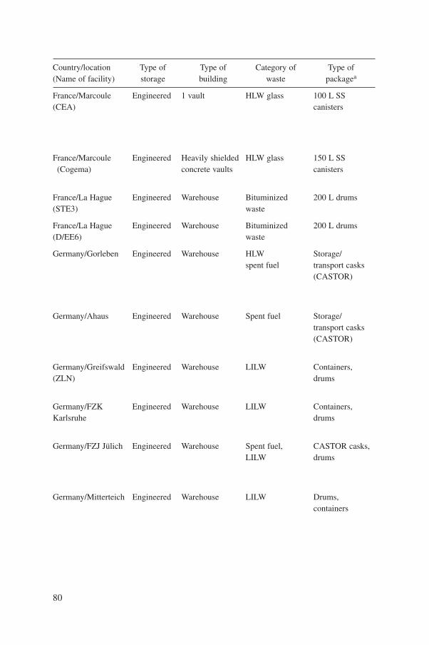
80
Country/location Type of Type of Category of Type of(Name of facility) storage building waste packagea
France/Marcoule Engineered 1 vault HLW glass 100 L SS(CEA) canisters
France/Marcoule Engineered Heavily shielded HLW glass 150 L SS(Cogema) concrete vaults canisters
France/La Hague Engineered Warehouse Bituminized 200 L drums(STE3) waste
France/La Hague Engineered Warehouse Bituminized 200 L drums(D/EE6) waste
Germany/Gorleben Engineered Warehouse HLW Storage/spent fuel transport casks
(CASTOR)
Germany/Ahaus Engineered Warehouse Spent fuel Storage/transport casks(CASTOR)
Germany/Greifswald Engineered Warehouse LILW Containers,(ZLN) drums
Germany/FZK Engineered Warehouse LILW Containers,Karlsruhe drums
Germany/FZJ Jülich Engineered Warehouse Spent fuel, CASTOR casks,LILW drums
Germany/Mitterteich Engineered Warehouse LILW Drums,containers
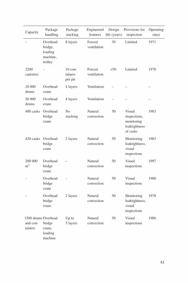
81
Package Package Engineered Design Provisions for OperatingCapacity
handling stacking features life (years) inspection since
– Overhead 8 layers Forced 30 Limited 1971bridge, ventilationloading machine,trolley
2200 – 10 con- Forced <50 Limited 1978canisters tainers ventilation
per pit
20 000 Overhead 4 layers Ventilation – – –drums crane
36 000 Overhead 4 layers Ventilation – – –drums crane
400 casks Overhead No Natural 50 Visual 1983bridge stacking convection inspections,crane monitoring
leaktightnessof casks
420 casks Overhead 2 layers Natural 50 Monitoring 1983bridge convection leaktightness,crane visual
inspections
200 000 Overhead – Natural 50 Visual 1997m3 bridge convection inspections
crane
– Overhead – Natural 50 Visual 1980bridge convection inspectionscrane
– Overhead 2 layers Natural 50 Monitoring 1978bridge convection leaktightness,crane visual
inspections
1500 drums Overhead Up to Natural 50 Visual 1986and con- bridge 5 layers convection inspectionstainers crane,
loadingmachine
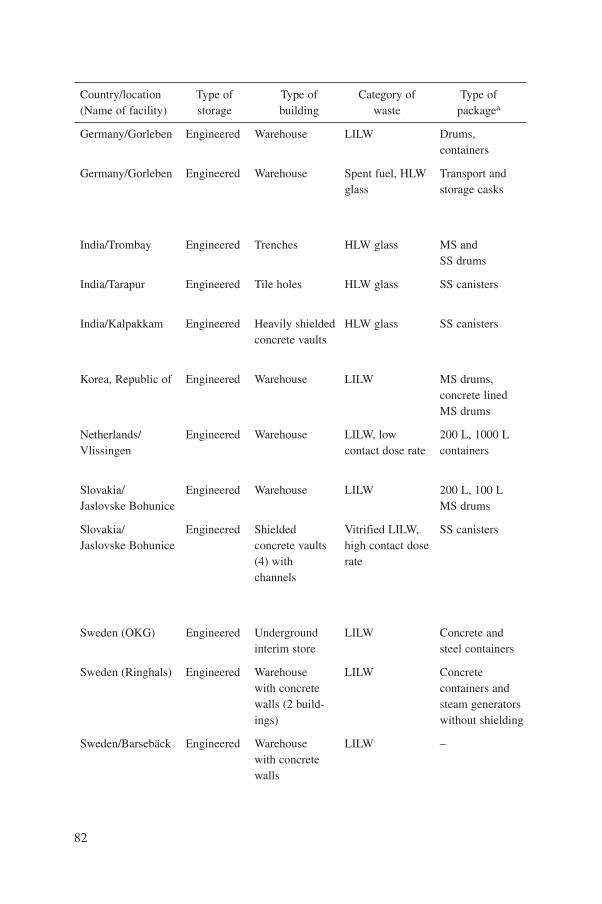
82
Country/location Type of Type of Category of Type of(Name of facility) storage building waste packagea
Germany/Gorleben Engineered Warehouse LILW Drums,containers
Germany/Gorleben Engineered Warehouse Spent fuel, HLW Transport andglass storage casks
India/Trombay Engineered Trenches HLW glass MS andSS drums
India/Tarapur Engineered Tile holes HLW glass SS canisters
India/Kalpakkam Engineered Heavily shielded HLW glass SS canistersconcrete vaults
Korea, Republic of Engineered Warehouse LILW MS drums,concrete lined MS drums
Netherlands/ Engineered Warehouse LILW, low 200 L, 1000 LVlissingen contact dose rate containers
Slovakia/ Engineered Warehouse LILW 200 L, 100 LJaslovske Bohunice MS drums
Slovakia/ Engineered Shielded Vitrified LILW, SS canistersJaslovske Bohunice concrete vaults high contact dose
(4) with ratechannels
Sweden (OKG) Engineered Underground LILW Concrete andinterim store steel containers
Sweden (Ringhals) Engineered Warehouse LILW Concretewith concrete containers andwalls (2 build- steam generatorsings) without shielding
Sweden/Barsebäck Engineered Warehouse LILW –with concretewalls
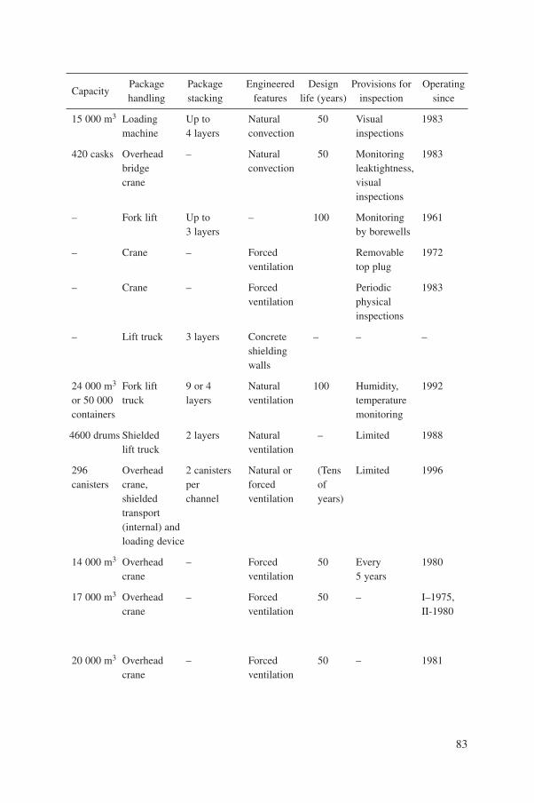
83
Package Package Engineered Design Provisions for OperatingCapacity
handling stacking features life (years) inspection since
15 000 m3 Loading Up to Natural 50 Visual 1983machine 4 layers convection inspections
420 casks Overhead – Natural 50 Monitoring 1983bridge convection leaktightness,crane visual
inspections
– Fork lift Up to – 100 Monitoring 19613 layers by borewells
– Crane – Forced Removable 1972ventilation top plug
– Crane – Forced Periodic 1983ventilation physical
inspections
– Lift truck 3 layers Concrete – – –shieldingwalls
24 000 m3 Fork lift 9 or 4 Natural 100 Humidity, 1992or 50 000 truck layers ventilation temperaturecontainers monitoring
4600 drums Shielded 2 layers Natural – Limited 1988lift truck ventilation
296 Overhead 2 canisters Natural or (Tens Limited 1996canisters crane, per forced of
shielded channel ventilation years)transport(internal) andloading device
14 000 m3 Overhead – Forced 50 Every 1980crane ventilation 5 years
17 000 m3 Overhead – Forced 50 – I–1975,crane ventilation II-1980
20 000 m3 Overhead – Forced 50 – 1981crane ventilation

84
Country/location Type of Type of Category of Type of(Name of facility) storage building waste packagea
Sweden/Studsvik Engineered Underground LILW 200 L drums,interim storage concrete and
MS containers
Sweden (CLAB) Engineered Underground LILW, spent SS basketsinterim fuel mainlystorage with4 water pools
Switzerland/ Engineered Warehouse LILW up to MS drums,Würenlingen surface rate concrete
2 mSv/h containers
UK/Sellafield Engineered Shielded LILW, high dose 500 L SS drumsconcrete rate, encapsulatedvaults (3 stores) hulls and sludges
UK/Sellafield Engineered Heavy shielded HLW glass 150 L SS vault canisters
UK/Sellafield Engineered Warehouse LILW, low 200 L MS and(several) contact dose 500 L SS drums
a waste
UK/Sellafield Engineered Concrete vault LILW, high 3 m3 MS boxcontact dose rate concrete lined
USA/Hanfordb Engineered Multiple bldg. LILW, a waste Drums, boxes
Subsurface Retrievable 200 L drumstrenches
Area Asphalt pad
a SS – stainless steel; MS – mild steel; MSG – mild steel galvanized; PE – polyethylene.
b Hanford is an example of DOE sites including Rocky Flats Environmental Technology Site, Idaho National Engineering Laboratory, Los Alamos National Laboratory andSavannah River Site, all of which have several forms of storage for radioactive waste awaiting disposal. Some sites also feature subsurface and area storage.

85
Package Package Engineered Design Provisions for OperatingCapacity
handling stacking features life (years) inspection since
20 000 m3 Overhead – Forced 50 Every 1984crane ventilation 5 years
12 000 m3 Overhead – Forced – – 1985crane ventilation
2000 m3 Overhead 8 layers Forced > 35 Limited 1992bridge ventilationcrane
60 000 Overhead 12 stillages, Building 50 Visual, on 1990drums bridge 4 drums ventilation sample
crane per stillage retrieved
8000 Charging 10 layers Natural 50 No 1990canisters machine in timble convection
tube
50 000 Shielded 4 layers Monitored 50 Yes 1960drums forklift ventilation
truck
1836 boxes Remotely 3 layers Building 50 – 1990operated ventilationtrolley
40 000 Fork lift 1 or – 20 Regular 1993drums
Fork lift4 layers
– None 1970as needed
Fork lift – 1993

REFERENCES
[1] FOOD AND AGRICULTURE ORGANIZATION OF THE UNITED NATIONS,INTERNATIONAL ATOMIC ENERGY AGENCY, INTERNATIONAL LABOURORGANISATION, OECD NUCLEAR ENERGY AGENCY, PAN AMERICANHEALTH ORGANIZATION, WORLD HEALTH ORGANIZATION, InternationalBasic Safety Standards for Protection against Ionizing Radiation and for the Safety ofRadiation Sources, Safety Series No. 115, IAEA, Vienna (1996).
[2] INTERNATIONAL ATOMIC ENERGY AGENCY, The Principles of Radioactive WasteManagement, Safety Series No. 111-F, IAEA, Vienna (1995).
[3] INTERNATIONAL COMMISSION ON RADIOLOGICAL PROTECTION, RadiationProtection Principles for the Disposal of Solid Radioactive Waste, Publication 46,Pergamon Press, Oxford and New York (1986).
[4] INTERNATIONAL COMMISSION ON RADIOLOGICAL PROTECTION, 1990Recommendations of the International Commission on Radiological Protection,Publication 60, Pergamon Press, Oxford and New York (1991).
[5] INTERNATIONAL ATOMIC ENERGY AGENCY, Radioactive Waste ManagementGlossary, IAEA, Vienna (1993).
[6] INTERNATIONAL ATOMIC ENERGY AGENCY, Containers for Packaging of SolidLow and Intermediate Level Radioactive Wastes, Technical Reports Series No. 355,IAEA, Vienna (1993).
[7] INTERNATIONAL ATOMIC ENERGY AGENCY, Regulations for the Safe Transportof Radioactive Material – 1996 Edition, Safety Standards Series No. ST-1, IAEA,Vienna (1996).
[8] INTERNATIONAL ATOMIC ENERGY AGENCY, Classification of Radioactive Waste,Safety Series No. 111-G-1.1, IAEA, Vienna (1994).
[9] INTERNATIONAL ATOMIC ENERGY AGENCY, Status of Technology for VolumeReduction and Treatment of Low and Intermediate Level Solid Radioactive Waste,Technical Reports Series No. 360, IAEA, Vienna (1994).
[10] INTERNATIONAL ATOMIC ENERGY AGENCY, Advances in Technologies for theTreatment of Low and Intermediate Level Radioactive Liquid Wastes, Technical ReportsSeries No. 370, IAEA, Vienna (1994).
[11] INTERNATIONAL ATOMIC ENERGY AGENCY, Improved Cement Solidification ofLow and Intermediate Level Radioactive Wastes, Technical Reports Series No. 350,IAEA, Vienna (1993).
[12] INTERNATIONAL ATOMIC ENERGY AGENCY, Bituminization Processes toCondition Radioactive Wastes, Technical Reports Series No. 352, IAEA, Vienna (1993).
[13] INTERNATIONAL ATOMIC ENERGY AGENCY, Immobilization of Low andIntermediate Level Radioactive Wastes with Polymers, Technical Reports Series No. 289(1988).
[14] INTERNATIONAL ATOMIC ENERGY AGENCY, Design and Operation of HighLevel Waste Vitrification and Storage Facilities, Technical Reports Series No. 339,IAEA, Vienna (1992).
87
88
[15] INTERNATIONAL ATOMIC ENERGY AGENCY, Application of Exemption
Principles to the Recycle and Reuse of Materials from Nuclear Facilities, Safety Series
No. 111-P-1.1, IAEA, Vienna (1992).[16] INTERNATIONAL ATOMIC ENERGY AGENCY, Characterization of Radioactive
Waste Forms and Packages, Technical Reports Series No. 383, IAEA, Vienna (1997).[17] INTERNATIONAL ATOMIC ENERGY AGENCY, Storage of Radioactive Waste,
IAEA-TECDOC-653, Vienna (1992).[18] INTERNATIONAL ATOMIC ENERGY AGENCY, Treatment and Conditioning of
Radioactive Solid Wastes, IAEA-TECDOC-655, Vienna (1992).
89
CONTRIBUTORS TO DRAFTING AND REVIEW
Advocat, T. Centre d’études nucléaires de la Vallée du Rhône, France
Ahmed, J. Bhabha Atomic Research Centre, India
Brücher, H. Forschungszentrum Jülich GmbH, Germany
Dellero, N. NUSYS–Transnucléaire, France
Devezeaux, J.G. COGEMA, France
El-Sourogy, M.M. Atomic Energy Authority, Egypt
Gestermann, G. Gesellschaft für Nuklear-Service mbH, Germany
Goldschmidt, A. National Atomic Energy Commission, Argentina
Johnsson, B. Studsvik Radwaste AB, Sweden
Knecht, B. Nuclear Safety Inspectorate (HSK), Switzerland
Lee, M.C. Korea Atomic Energy Research Institute,
Republic of Korea
Neubauer, J. Austrian Research Centre Seibersdorf, Austria
Reynders, R. Belgoprocess, Belgium
Richards, P. British Nuclear Fuels plc, United Kingdom
Risoluti, P. Italian National Agency for New Technology, Energy and the
Environment (ENEA), Italy
Rozain, J.P. Centre d’études nucléaires de Cadarache, France
Salzer, P. Nuclear Regulatory Authority, Slovakia
Sorlie, A. Norwegian Radiation Protection Authority, Norway

90
Stefanova, I. Institute for Nuclear Research and Nuclear Energy,
Bulgaria
Stupka, R. Los Alamos National Laboratory, United States of America
Tsyplenkov, V. International Atomic Energy Agency
Vokal, A. Nuclear Research Institute, Czech Republic
Welbergen, J. Central Organization for Radioactive Waste (COVRA),
Netherlands
Yao, X. Nuclear Fuel Complex, China
Consultants Meetings
Vienna, Austria: 11–15 December 1995, 25–29 November 1996
Technical Committee Meeting
Vienna, Austria: 23–27 September 1996