international iso standard...
TRANSCRIPT

Reference numberISO 10438-1:2007(E)
© ISO 2007
INTERNATIONAL STANDARD
ISO10438-1
Second edition2007-12-15
Petroleum, petrochemical and natural gas industries — Lubrication, shaft-sealing and control-oil systems and auxiliaries —Part 1: General requirements
Industries du pétrole, de la pétrochimie et du gaz naturel — Systèmes de lubrification, systèmes d'étanchéité, systèmes d'huile de régulation et leurs auxiliaires —
Partie 1: Exigences générales
Copyright International Organization for Standardization Provided by IHS under license with ISO
Not for ResaleNo reproduction or networking permitted without license from IHS
--`,,```,,,,````-`-`,,`,,`,`,,`---

ISO 10438-1:2007(E)
PDF disclaimer This PDF file may contain embedded typefaces. In accordance with Adobe's licensing policy, this file may be printed or viewed but shall not be edited unless the typefaces which are embedded are licensed to and installed on the computer performing the editing. In downloading this file, parties accept therein the responsibility of not infringing Adobe's licensing policy. The ISO Central Secretariat accepts no liability in this area.
Adobe is a trademark of Adobe Systems Incorporated.
Details of the software products used to create this PDF file can be found in the General Info relative to the file; the PDF-creation parameters were optimized for printing. Every care has been taken to ensure that the file is suitable for use by ISO member bodies. In the unlikely event that a problem relating to it is found, please inform the Central Secretariat at the address given below.
COPYRIGHT PROTECTED DOCUMENT © ISO 2007 All rights reserved. Unless otherwise specified, no part of this publication may be reproduced or utilized in any form or by any means, electronic or mechanical, including photocopying and microfilm, without permission in writing from either ISO at the address below or ISO's member body in the country of the requester.
ISO copyright office Case postale 56 • CH-1211 Geneva 20 Tel. + 41 22 749 01 11 Fax + 41 22 749 09 47 E-mail [email protected] Web www.iso.org
Published in Switzerland
ii © ISO 2007 – All rights reserved
Copyright International Organization for Standardization Provided by IHS under license with ISO
Not for ResaleNo reproduction or networking permitted without license from IHS
--`,,```,,,,````-`-`,,`,,`,`,,`---

ISO 10438-1:2007(E)
© ISO 2007 – All rights reserved iii
Contents Page
Foreword............................................................................................................................................................ iv Introduction ........................................................................................................................................................ v 1 Scope ..................................................................................................................................................... 1 2 Normative references ........................................................................................................................... 1 3 Terms, abbreviated terms and definitions ......................................................................................... 2 3.1 Terms and definitions........................................................................................................................... 2 3.2 Abbreviated terms ................................................................................................................................ 8 4 General................................................................................................................................................. 10 4.1 Dimensions and units......................................................................................................................... 10 4.2 Design .................................................................................................................................................. 10 4.3 System selection................................................................................................................................. 10 4.4 Pressure design code......................................................................................................................... 10 4.5 Basic design........................................................................................................................................ 10 4.6 Welding ................................................................................................................................................ 11 4.7 Statutory requirements ...................................................................................................................... 11 4.8 Documentation requirements............................................................................................................ 11 5 Piping ................................................................................................................................................... 11 5.1 General................................................................................................................................................. 11 5.2 Oil piping ............................................................................................................................................. 18 5.3 Instrument piping and tubing ............................................................................................................ 18 5.4 Process piping .................................................................................................................................... 18 5.5 Intercoolers and aftercoolers ............................................................................................................ 19 6 Instrumentation, control and electrical systems............................................................................. 20 6.1 General................................................................................................................................................. 20 6.2 Alarm, shutdown and control systems............................................................................................. 20 6.3 Instrumentation................................................................................................................................... 23 6.4 Electrical systems............................................................................................................................... 28 7 Inspection testing, and preparation for shipment........................................................................... 29 7.1 General................................................................................................................................................. 29 7.2 Inspection ............................................................................................................................................ 30 7.3 Testing ................................................................................................................................................. 32 7.4 Preparation for shipment ................................................................................................................... 33 8 Vendor's data ...................................................................................................................................... 34 8.1 General................................................................................................................................................. 34 8.2 Proposals............................................................................................................................................. 35 8.3 Contract data....................................................................................................................................... 36 Annex A (informative) Datasheets .................................................................................................................. 39 Annex B (informative) Symbols ...................................................................................................................... 40 Annex C (informative) Vendor drawing and data requirements (VDDR) .................................................... 42 Annex D (informative) Oil or gas filter performance and oil-system cleanliness testing ......................... 46 Annex E (informative) International materials specifications...................................................................... 57 Annex F (informative) Explanation of reservoir levels ................................................................................. 58 Bibliography ..................................................................................................................................................... 60
Copyright International Organization for Standardization Provided by IHS under license with ISO
Not for ResaleNo reproduction or networking permitted without license from IHS
--`,,```,,,,````-`-`,,`,,`,`,,`---
ISO 10438-1:2007(E)
iv © ISO 2007 – All rights reserved
Foreword
ISO (the International Organization for Standardization) is a worldwide federation of national standards bodies (ISO member bodies). The work of preparing International Standards is normally carried out through ISO technical committees. Each member body interested in a subject for which a technical committee has been established has the right to be represented on that committee. International organizations, governmental and non-governmental, in liaison with ISO, also take part in the work. ISO collaborates closely with the International Electrotechnical Commission (IEC) on all matters of electrotechnical standardization.
International Standards are drafted in accordance with the rules given in the ISO/IEC Directives, Part 2.
The main task of technical committees is to prepare International Standards. Draft International Standards adopted by the technical committees are circulated to the member bodies for voting. Publication as an International Standard requires approval by at least 75 % of the member bodies casting a vote.
Attention is drawn to the possibility that some of the elements of this document may be the subject of patent rights. ISO shall not be held responsible for identifying any or all such patent rights.
ISO 10438-1 was prepared by Technical Committee ISO/TC 67, Materials, equipment and offshore structures for petroleum, petrochemical and natural gas industries, Subcommittee SC 6, Processing equipment and systems.
This second edition cancels and replaces the first edition (ISO 10438-1:2003), which has been technically revised.
ISO 10438 consists of the following parts, under the general title Petroleum, petrochemical and natural gas industries — Lubrication, shaft-sealing and control-oil systems and auxiliaries:
⎯ Part 1: General requirements
⎯ Part 2: Special-purpose oil systems
⎯ Part 3: General-purpose oil systems
⎯ Part 4: Self-acting gas seal support systems
Copyright International Organization for Standardization Provided by IHS under license with ISO
Not for ResaleNo reproduction or networking permitted without license from IHS
--`,,```,,,,````-`-`,,`,,`,`,,`---

ISO 10438-1:2007(E)
© ISO 2007 – All rights reserved v
Introduction
This part of ISO 10438 was developed jointly with API 614, 5th edition, together with the other three parts of ISO 10438.
NOTE API 614 is equivalent to ISO 10438 (all parts).
Users of this part of ISO 10438 should be aware that further or differing requirements can be needed for individual applications. This part of ISO 10438 is not intended to inhibit a vendor from offering, or the purchaser from accepting, alternative equipment or engineering solutions for the individual application. This can be particularly appropriate where there is innovative or developing technology. Where an alternative is offered, the vendor should identify any variations from this part of ISO 10438 and provide details.
This part of ISO 10438 requires the purchaser to specify certain details and features.
A bullet (•) at the beginning of a clause or subclause indicates that either a decision is required or further information is to be provided by the purchaser. This information should be indicated on the datasheet(s); otherwise it should be stated in the quotation request or in the order.
In this International Standard, United States customary (USC) units are included in brackets for information.
Copyright International Organization for Standardization Provided by IHS under license with ISO
Not for ResaleNo reproduction or networking permitted without license from IHS
--`,,```,,,,````-`-`,,`,,`,`,,`---

Copyright International Organization for Standardization Provided by IHS under license with ISO
Not for ResaleNo reproduction or networking permitted without license from IHS
--`,,```,,,,````-`-`,,`,,`,`,,`---

INTERNATIONAL STANDARD ISO 10438-1:2007(E)
© ISO 2007 – All rights reserved 1
Petroleum, petrochemical and natural gas industries — Lubrication, shaft-sealing and control-oil systems and auxiliaries —
Part 1: General requirements
1 Scope
This part of ISO 10438 specifies general requirements for lubrication systems, oil-type shaft-sealing systems, dry-gas face-type shaft-sealing systems and control-oil systems for general- or special-purpose applications. General-purpose applications are limited to lubrication systems. These systems can serve equipment such as compressors, gears, pumps and drivers.
This part of ISO 10438 is intended to be used in conjunction with ISO 10438-2, ISO 10438-3 or ISO 10438-4, as appropriate.
2 Normative references
The following referenced documents are indispensable for the application of this document. For dated references, only the edition cited applies. For undated references, the latest edition of the referenced document (including any amendments) applies.
ISO 7-1, Pipe threads where pressure-tight joints are made on the threads — Part 1: Dimensions, tolerances and designation
ISO 10434, Bolted bonnet steel gate valves for the petroleum, petrochemical and allied industries
ISO 13706, Petroleum, petrochemical and natural gas industries — Air-cooled heat exchangers
ISO 15649, Petroleum and natural gas industries — Piping
ISO 15761, Steel gate, globe and check valves for sizes DN 100 and smaller, for the petroleum and natural gas industries
ISO 16812, Petroleum, petrochemical and natural gas industries — Shell-and-tube heat exchangers
IEC 60079 (all parts), Electrical apparatus for explosive gas atmospheres
IEC 60529, Degrees of protection provided by enclosures (IP Code)
ANSI/API RP 551, Process Measurement Instrumentation
API RP 520 (all parts), Sizing, Selection, and Installation of Pressure-Relieving Devices in Refineries
API STD 526, Flanged Steel Pressure Relief Valves
Copyright International Organization for Standardization Provided by IHS under license with ISO
Not for ResaleNo reproduction or networking permitted without license from IHS
--`,,```,,,,````-`-`,,`,,`,`,,`---
ISO 10438-1:2007(E)
2 © ISO 2007 – All rights reserved
API STD 611, General-Purpose Steam Turbines for Petroleum, Chemical and Gas Industry Services
API RP 686-96, Machinery Installation and Installation Design
ASME B1.1, Unified Inch Screw Threads (UN and UNR Thread Form)
ASME B16.5, Pipe Flanges and Flanged Fittings: NPS 1/2 through 24
ANSI/ASME B16.11, Forged Fittings, Socket-Welding and Threaded
ANSI/ASME Y14.2M, Line Conventions and Lettering
ASTM A193/A193M-07, Standard Specification for Alloy-Steel and Stainless Steel Bolting Materials for High Temperature or High Pressure Service and Other Special Purpose Applications
ASTM A194/A194M-07, Standard Specification for Carbon and Alloy Steel Nuts for Bolts for High Pressure or High Temperature Service, or Both
ASTM E94, Standard Guide for Radiographic Examination
ASTM E709, Standard Guide for Magnetic Particle Examination
ANSI/AWS D1.1/D1.1M, Structural Welding Code — Steel
ISA 18.1, Annunciator Sequences and Specifications
NEMA 250, Enclosures for Electrical Equipment (1 000 Volts Maximum)
TEMA, Standards of the Tubular Exchanger Manufacturers Association, 8th ed.
3 Terms, abbreviated terms and definitions
For the purposes of this document, the following terms, definitions and abbreviated terms apply.
3.1 Terms and definitions
3.1.1 alarm point preset value of a parameter at which an alarm warns of a condition requiring corrective action
3.1.2 block-in time period required after the driver is tripped to isolate a piece of equipment, such as a compressor, from its system and to depressurize it
3.1.3 booster pump oil pump that takes suction from the discharge of another pump to provide oil at a higher pressure
3.1.4 coast-down time period required after the driver is tripped for the equipment to come to rest
3.1.5 components machinery and hardware items, such as reservoirs, pumps, coolers, filters, valves, and instruments, that are part of the system
Copyright International Organization for Standardization Provided by IHS under license with ISO
Not for ResaleNo reproduction or networking permitted without license from IHS
--`,,```,,,,````-`-`,,`,,`,`,,`---

ISO 10438-1:2007(E)
© ISO 2007 – All rights reserved 3
3.1.6 console total system whose components and controls are packaged as a single unit on a continuous or joined baseplate
NOTE 1 With a console, the purchaser is required only to make external connections.
NOTE 2 Rundown tanks and seal-oil tanks that are separately mounted, as well as other items such as instrumentation mounted on the equipment, are not part of the console.
3.1.7 continuous-flow transfer valve valve that can simultaneously divert both inlet and outlet flows from one component to its installed spare equipment without altering the continuity of full flow through the transfer valve to the equipment
3.1.8 control oil oil required to operate such components as relays, servomotors and power pistons on the main equipment
3.1.9 cool-off time period during which oil has to be circulated through the equipment to prevent heat damage after the driver is tripped
3.1.10 device position
3.1.10.1 normally open de-energized position of a device (e.g. automatically controlled electric switch or valve) remaining in an open position during operation unless energized
NOTE During operation of the equipment, the positions of these devices are not necessarily the same as their on-the-shelf positions.
3.1.10.2 normally closed de-energized position of a device (e.g. automatically controlled electric switch or valve) remaining in a closed position during operation unless energized
NOTE During operation of the equipment, the positions of these devices are not necessarily the same as their on-the-shelf positions.
3.1.11 double seal seal arrangement that utilizes two seal faces in an opposed configuration, whereby sealing gas is injected between the seal faces
NOTE See tandem seal (3.1.49).
3.1.12 dry gas seal system self-acting dry gas seal module and all other components necessary for operation of the self-acting dry gas seal
3.1.13 equipment main machinery served by the oil or gas system
Copyright International Organization for Standardization Provided by IHS under license with ISO
Not for ResaleNo reproduction or networking permitted without license from IHS
--`,,```,,,,````-`-`,,`,,`,`,,`---

ISO 10438-1:2007(E)
4 © ISO 2007 – All rights reserved
3.1.14 fail safe system or component that causes the equipment to revert to a permanently safe condition (shutdown and/or depressurized) in the event of a component failure or failure of the energy supply to the system
3.1.15 gas-seal module arrangement of piping, filters and instrumentation used to control and monitor the pressure or flow of seal, buffer or separation gas to the equipment shaft end seals
3.1.16 gauge board unenclosed bracket or plate used to support and display gauges, switches and other instruments
NOTE A gauge board is not a panel. A panel is an enclosure. Refer to 3.1.31 for the definition of a panel.
3.1.17 general-purpose usually spared or in non-critical service
3.1.18 local mounted on or near the equipment or console
3.1.19 mission time duration of the mission
NOTE Mission time begins when the equipment or system is 100 % operational, i.e. equipment or system capability has returned to engineered capability, and the equipment or system is ready for service. The mission time ends when the equipment or system can no longer meet the defined mission objectives. To meet the business plan, it is necessary that the actual mission time be equal to or greater than the planned mission time.
3.1.20 main oil pump oil pump that is normally in operation
3.1.21 maximum allowable temperature maximum continuous temperature for which the manufacturer has designed the equipment (or any part to which the term is referred) when handling the specified fluid at the specified pressure
3.1.22 maximum allowable working pressure maximum continuous pressure for which the manufacturer has designed the console or components when handling the specified fluid at the maximum allowable temperature
3.1.23 maximum discharge pressure ⟨centrifugal pump⟩ maximum specified suction pressure plus the maximum differential pressure the pump with the finished impeller is able to develop when operating at rated speed with fluid of the specified normal relative density (specific gravity)
3.1.24 maximum sealing pressure highest pressure expected at the seals during any specified static or operating conditions and during start-up and shutdown
NOTE Considerations should include both relief valve settings and relief-valve accumulation pressure.
Copyright International Organization for Standardization Provided by IHS under license with ISO
Not for ResaleNo reproduction or networking permitted without license from IHS
--`,,```,,,,````-`-`,,`,,`,`,,`---

ISO 10438-1:2007(E)
© ISO 2007 – All rights reserved 5
3.1.25 multiple-package total oil supply system whose components are separated into individually packaged units
NOTE With this arrangement, the purchaser is required only to install the interconnections between the packages and the external connections.
3.1.26 normal flow total amount of fluid required by equipment components such as bearings, seals, couplings and steady-state controls excluding transient flow for controls or fluid bypassed directly back to the reservoir
3.1.27 normal operating point point at which normal operation is expected and optimum efficiency is desired
NOTE This point is usually the point at which the vendor certifies that the performance is within the tolerances stated in the relevant standard.
3.1.28 observed when the purchaser is notified of the timing of the inspection or test and the inspection or test is performed as scheduled, whether or not the purchaser or his representative is present
3.1.29 owner final recipient of the equipment, who may delegate another agent as the purchaser of the equipment
3.1.30 package total system, or part of a system, whose components are mounted on a single baseplate
NOTE A package is complete in all respects, including controls and instrumentation.
3.1.31 panel enclosure used to mount, display and protect gauges, switches and other instruments
NOTE Instruments in a panel may be open or enclosed by the panel. (See 3.1.16.)
3.1.32 pressure-limiting valve PLV automatic pressure-limiting device, which opens in proportion to the increase in pressure over the opening set pressure and automatically closes when the upstream pressure is reduced below the set pressure, and which is actuated by the static pressure upstream of the valve
NOTE 1 These devices are not necessarily tight shutoff when closed, i.e. they may have a small leakage flow when closed. These devices are designed for liquid service only and are normally used for limiting the discharge pressure of positive-displacement-type oil pumps and the downstream pressure of fail-open oil-pressure regulating valves when necessary.
NOTE 2 PLVs require a flowing test system in order to test. Normally, these valves are, therefore, tested in the system on which they are installed.
Copyright International Organization for Standardization Provided by IHS under license with ISO
Not for ResaleNo reproduction or networking permitted without license from IHS
--`,,```,,,,````-`-`,,`,,`,`,,`---

ISO 10438-1:2007(E)
6 © ISO 2007 – All rights reserved
3.1.33 pressure safety valve relief valve PSV automatic pressure-relieving device, which opens in proportion to the increase in pressure over the opening set pressure, has a rapid full opening or pop action characteristic and is actuated by the static pressure upstream of the valve
NOTE The device automatically closes when the upstream pressure is reduced below the set pressure. These devices are considered to be tight shutoff when closed and are normally used in gas, vapour or liquid service.
3.1.34 purchaser agency that issues the order and specification to the vendor
NOTE The purchaser can be the owner of the plant in which the equipment is installed or the owner's appointed agent.
3.1.35 remote located away from the equipment or the console, typically in a control house
3.1.36 seal buffer gas clean gas supplied to the high-pressure side of a seal
NOTE 1 This term was originally used on oil seals and has been replaced with the term “seal gas supply” for clean gas that also serves as the sealing gas for a dry gas seal.
NOTE 2 See ISO 10438-4:2007, Figures D.1 to D.4.
3.1.37 seal gas dry, filtered gas supplied to the high-pressure side of a self-acting gas seal
NOTE See ISO 10438-4:2007, Figures D.1 to D.4.
3.1.38 seal gas leakage gas that flows from the high-pressure side of the seal to the low-pressure side of the seal
3.1.39 secondary seal-gas supply clean purge gas supplied to the area between the seals of a tandem self-acting gas seal having an intermediate labyrinth
NOTE This gas is at a pressure lower than the process pressure.
3.1.40 self-contained regulator regulating valve assembly that utilizes or internally senses the controlling pressure or temperature
3.1.41 separation gas supply of inert gas or air fed into the region between the seal and the shaft bearing
3.1.42 settling-out pressure maximum pressure the system can reach under static conditions
Copyright International Organization for Standardization Provided by IHS under license with ISO
Not for ResaleNo reproduction or networking permitted without license from IHS
--`,,```,,,,````-`-`,,`,,`,`,,`---

ISO 10438-1:2007(E)
© ISO 2007 – All rights reserved 7
3.1.43 shaft-driven pump oil pump driven by the shaft of one of the main machines served by the oil system
3.1.44 shutdown point preset value of a parameter at which automatic or manual shutdown of the system is required
3.1.45 special-purpose application application for which the equipment is designed for uninterrupted, continuous operation in critical service and for which there is usually no spare equipment
3.1.46 standby pump oil pump that is capable, either automatically or manually, of being immediately brought up to operating speed, and that is capable of operating continuously
3.1.47 standby service normally idle piece of equipment that is capable of immediate automatic or manual start-up and continuous operation
3.1.48 stilling tube pipe extending into the reservoir from the connection to below pump suction-loss level to prevent splashing and provide free release of foam and gas
NOTE 1 A stilling tube is typically used for non-pressurized returns and has an open top or vent holes to equalize to reservoir pressure.
NOTE 2 See ISO 10438-2:2007, Figure B.24.
3.1.49 tandem seal seal arrangement which utilizes two seal faces oriented in the same direction, whereby the outboard seal face acts as a backup seal to the inboard or primary seal face
NOTE 1 A special arrangement of this seal incorporates an intermediate labyrinth seal to allow an inert sealing gas to be injected between the seal faces. In this arrangement, the backup or outboard seal face seals against the inert sealing gas and is not exposed to the process gas.
NOTE 2 See double seal (3.1.11).
3.1.50 unit responsibility responsibility for coordinating the technical aspects of the equipment and all auxiliary systems included in the scope of the order
NOTE Responsibility for such factors as the power requirements, speed, rotation, general arrangement, couplings, dynamics, noise, lubrication, sealing system, material test reports, instrumentation, piping and testing of components is included.
3.1.51 vendor supplier agency that manufactures, sells and provides service support for the equipment
NOTE The vendor may be the manufacturer of the equipment or the manufacturer's agent and normally is responsible for service support.
Copyright International Organization for Standardization Provided by IHS under license with ISO
Not for ResaleNo reproduction or networking permitted without license from IHS
--`,,```,,,,````-`-`,,`,,`,`,,`---

ISO 10438-1:2007(E)
8 © ISO 2007 – All rights reserved
3.1.52 vent gas seal gas leakage that is taken away by the vent system
3.1.53 vent system arrangement of piping and valves used to take gas to a safe location
3.1.54 witnessed inspection or test where the purchaser is notified of the timing of the inspection or test and a hold is placed on the inspection or test until the purchaser or his representative is in attendance
3.2 Abbreviated terms
AS air supply
BWG Birmingham wire gauge
DN nominal diameter
DP differential pressure indicator
FAL flow alarm low
FC fail closed
FCV flow control valve
FE flow element
FG flow glass
FI flow indicator
FIC flow indicator controller
FL fail locked (when labelling a valve)
FO fail open (when labelling a valve)
FRO flow restriction orifice
FT flow transmitter
FY I/P (current to pneumatic) interposing relay
LC level controller
LG level gauge
LIC level indicator controller
LSH level switch high
LSHH level switch high high
LSL level switch low
Copyright International Organization for Standardization Provided by IHS under license with ISO
Not for ResaleNo reproduction or networking permitted without license from IHS
--`,,```,,,,````-`-`,,`,,`,`,,`---
ISO 10438-1:2007(E)
© ISO 2007 – All rights reserved 9
LSLL level switch low low
LT level transmitter
LV level valve
LY level relay
NC normally closed
NDT non-destructive testing
NO normally open
NPS nominal pipe size
NPT national pipe thread (tapered)
P&ID process (piping) and instrument drawing
PCV pressure control valve
PDCV pressure differential control valve
PDI pressure differential indicator
PDS pressure differential switch
PDSH pressure differential switch high
PDSL pressure differential switch low
PDSLL pressure differential switch low low
PDT pressure differential transmitter
PI pressure indicator
PLV pressure-limiting valve
PN nominal pressure
PSH pressure switch high
PSHH pressure switch high high
PSL pressure switch low
PSLL pressure switch low low
PSV pressure safety (relief) valve
PT pressure transmitter
TC temperature controller
TCV temperature control valve
TI temperature indicator
Copyright International Organization for Standardization Provided by IHS under license with ISO
Not for ResaleNo reproduction or networking permitted without license from IHS
--`,,```,,,,````-`-`,,`,,`,`,,`---
ISO 10438-1:2007(E)
10 © ISO 2007 – All rights reserved
TIC temperature indicator controller
TS temperature switch
TSH temperature switch high
TSL temperature switch low
UNC unified national coarse thread
VDDR vendor drawing and data requirements
4 General
4.1 Dimensions and units
Drawings and maintenance dimensions shall be in SI units or United States customary (USC) units. Use of an SI datasheet indicates that SI units shall be used. Use of an USC datasheet indicates that USC units shall be used.
NOTE Dedicated datasheets for SI units and for USC units are provided in Annex A in each of the four parts of ISO 10438.
4.2 Design
The term “design” shall apply solely to parameters or features of the equipment supplied by the manufacturer. The term “design” should not be used in the purchaser's enquiry or specifications because it can create confusion in understanding the order.
EXAMPLES Design power, design pressure, design temperature, design speed.
4.3 System selection
4.3.1 Annexes in ISO 10438-2, ISO 10438-3 and ISO 10438-4 provide schemas and diagrams of typical complete lubrication, oil-type shaft-sealing, dry gas face-type shaft-sealing and control-oil systems. These schematics and diagrams illustrate the general philosophy and requirements of this part of ISO 10438 and are included to assist the purchaser in the selection of an appropriate system. Symbols shown on these schematics and diagrams are identified in Annex B of this part of ISO 10438. The purchaser and the vendor shall agree upon a mutually acceptable system before the order is released.
4.3.2 The purchaser shall define the scope of supply, the level of quality or the brand of components, the system type, the general arrangement (including plan and elevation views of the console orientation), the space available for the console, the service (special purpose or general purpose) and other requirements. Annexes C and D of this part of ISO 10438 are intended to assist in this definition.
4.4 Pressure design code
The pressure design code shall be specified or agreed by the purchaser. Pressure components shall comply with the pressure design code and the supplementary requirements in this part of ISO 10438.
4.5 Basic design
4.5.1 Equipment shall be designed for installation in accordance with API 686.
4.5.2 The equipment, including all auxiliaries, shall be suitable for operation under the environmental conditions specified. These conditions shall include whether the installation is indoors (heated or unheated) or outdoors (with or without a roof), maximum and minimum temperatures, unusual humidity, and dusty or corrosive conditions.
Copyright International Organization for Standardization Provided by IHS under license with ISO
Not for ResaleNo reproduction or networking permitted without license from IHS
--`,,```,,,,````-`-`,,`,,`,`,,`---
ISO 10438-1:2007(E)
© ISO 2007 – All rights reserved 11
4.5.3 The equipment, including all auxiliaries, shall be suitable for operation, using the utility stream conditions specified.
4.5.4 Spare and replacement parts shall meet all the criteria of the furnished system.
4.5.5 The vendor shall assume unit responsibility for all equipment and all auxiliary systems included in the scope of the order.
4.5.6 Where drilled check valves are provided, they shall be labelled with stainless steel tags stamped indicating that they are drilled and the size of the drilled hole.
NOTE Drilled check valves are sometimes utilized with shaft-driven pumps or atmospheric rundown tanks.
4.5.7 The purchaser and the vendor shall mutually determine the measures that shall be taken to comply with any governmental codes, regulations, ordinances or rules that are applicable to the equipment.
It is recommended that this be done as early as possible and preferably in the inquiry stage.
4.6 Welding
4.6.1 Welding of piping and pressure-containing parts, as well as any dissimilar-metal welds and weld repairs, shall be performed and inspected by operators and procedures qualified in accordance with the pressure design code or the piping system design code as appropriate.
4.6.2 In addition to the requirements of 4.6.1 and the applicable piping code, the purchaser may specify that additional radiography, magnetic particle inspection or liquid-penetrant inspection of specific welds on equipment and/or piping is required.
NOTE 1 ISO 15649 already includes a level of NDT inspection for piping.
NOTE 2 ISO 10438-3 systems do not require radiography of piping (see ISO 10438-3:2007, 5.1.2).
4.6.3 All welding other than that covered by the pressure design code or the piping systems design code such as welding on baseplates, non-pressure ducting, lagging and control panels shall be in accordance with a structural welding standard such as AWS D1.1, unless otherwise specified.
4.7 Statutory requirements
The purchaser and the vendor shall mutually determine the measures to be taken to comply with any governmental codes, regulations, ordinances or rules that are applicable to the equipment, its packaging and any preservatives used.
4.8 Documentation requirements
The hierarchy of documents shall be specified.
NOTE Typical documents include company and industry specifications, meeting notes and modifications to these documents.
5 Piping
5.1 General
5.1.1 Piping design and joint fabrication examination and inspection shall comply with ISO 15649.
NOTE 1 ISO 15649 includes ASME B31.3 as a normative reference, and for the purposes of this part of ISO 10438, the provisions are identical. See also CEN/TR 14549.
Copyright International Organization for Standardization Provided by IHS under license with ISO
Not for ResaleNo reproduction or networking permitted without license from IHS
--`,,```,,,,````-`-`,,`,,`,`,,`---
ISO 10438-1:2007(E)
12 © ISO 2007 – All rights reserved
NOTE 2 The alphanumeric designation of size used for reference purposes for components of a pipework system, when using the DN system, comprises the letters DN followed by a dimensionless whole number that is indirectly related to the nominal physical size in millimetres. The number following the letters DN does not represent a measurable value and it is not appropriate that they be used for calculation purposes except where specified in the relevant standard.
NOTE 3 The alphanumeric designation relating to pressure used for reference purposes for components of a pipework system, when using the PN system, comprises the letters PN followed by a convenient round, dimensionless number. For further information, see ISO 7268.
NOTE 4 It is intended that all equipment of the same nominal size (DN) designated by the same PN number have the same mating dimensions appropriate to the type of end connections.
The permissible working pressure depends upon the materials, design and working temperature and shall be selected from the pressure/temperature rating tables in corresponding standards.
5.1.2 Auxiliary systems are defined as piping systems that are in the following services:
a) Group I, Auxiliary process fluids (see Table 1):
1) sealing fluid,
2) gland and flushing fluid,
3) recirculation fluid,
4) balance gas,
5) buffer gas,
6) fuel gas or oil,
7) drains and vents associated with group I systems,
8) starting gas,
9) separation gas,
10) solvents injection;
b) Group II, Steam and air (see Table 2):
1) sealing steam,
2) steam injection,
3) water injection,
4) starting air,
5) instrument and control air,
6) drains and vents associated with group II systems;
c) Group III, Cooling water (see Table 3):
1) cooling water,
2) liquid wash (water based),
3) drains and vents associated with group III systems;
Copyright International Organization for Standardization Provided by IHS under license with ISO
Not for ResaleNo reproduction or networking permitted without license from IHS
--`,,```,,,,````-`-`,,`,,`,`,,`---

ISO 10438-1:2007(E)
© ISO 2007 – All rights reserved 13
d) Group IV, Lubricating, control and seal oil (see Table 4):
1) lubricating oil,
2) control oil,
3) seal oil (see 5.4 for seal oil contaminated with process fluid),
4) drains and vents associated with group IV systems.
Auxiliary systems shall comply with the requirements of Tables 1 through 6, except as modified in referencing standards, including references to Tables 1 through 6 in ISO 10438-2, ISO 10438-3 and ISO 10438-4.
NOTE Casing connections are covered in the associated equipment standards.
Table 1 — Minimum requirements for piping materials — Auxiliary process fluid
Pipe Austenitic stainless steel, (e.g. ASTM A312 type 304 or 316 or the equivalent material designation located in Annex E). Seamless, except Schedule 10S and 40S may be electric fusion welded. Seamless carbon steel (e.g. ASTM A106-B, A53-B or the equivalent material designation located in Annex E)
Pipe fitting Austenitic stainless steel, (e.g. ASTM A403 or the equivalent material designation located in Annex E, type 304 or 316 stainless steel). Seamless, except Schedule 10S and 40S may be electric fusion welded. Austenitic stainless steel, (e.g. ASTM A182 type 304 or 316 or the equivalent material designation located in Annex E), class 3000. Seamless carbon steel (e.g. ASTM A234 or the equivalent material designation located in Annex E). Carbon steel, (e.g. ASTM A105 or the equivalent material designation located in Annex E), class 3000
Flange Austenitic stainless steel, (e.g. ASTM A182 type 304 or 316 or the equivalent code material designation located in Annex E) weld neck or slip-on. Carbon steel (e.g. ASTM A105) or the equivalent material designation located in Annex E, weld neck or slip-on
Tubing Stainless steel, (ASTM A269 type 304 or 316 or the equivalent material designation located in Annex E)
Tube fittings Austenitic stainless steel type 304 or 316 (vendor's standard with purchaser's approval)
Gaskets For less than or equal to ANSI class 300: flat, non-asbestos type
For greater than or equal to ANSI class 600: spiral wound with non-asbestos filler, 304 or 316 windings and external centring ring
Flange bolting Refer to 5.1.28 and 5.1.29.
Valves Refer to 5.1.22, 5.1.23 and 5.1.24.
NOTE Threaded joints require seal welding; however, seal welding is not permitted on instruments or where disassembly is required for maintenance.
Copyright International Organization for Standardization Provided by IHS under license with ISO
Not for ResaleNo reproduction or networking permitted without license from IHS
--`,,```,,,,````-`-`,,`,,`,`,,`---

ISO 10438-1:2007(E)
14 © ISO 2007 – All rights reserved
Table 2 — Minimum requirements for piping materials — Steam and air
Pipe Seamless, carbon steel (e.g. ASTM A106-B, A53-B) or the equivalent material designation located in Annex E
Pipe fitting Seamless, carbon steel (e.g. ASTM A234 or the equivalent material designation located in Annex E)
Carbon steel (e.g. ASTM A105 class 3000 or the equivalent material designation located in Annex E)
Flange Carbon steel (e.g. ASTM A105 or the equivalent material designation located in Annex E), weld neck or slip-on
Tubing Stainless steel (e.g. ASTM A269 or the equivalent material designation located in Annex E), type 304 or 316
Tube fittings Stainless steel type 304 or 316 (vendor's standard)
Gaskets For less than or equal to ANSI class 300: flat, non-asbestos type
For greater than or equal to ANSI class 600: spiral wound with non-asbestos filler, 304 or 316 windings and external centring ring
Flange bolting Refer to 5.1.28 and 5.1.29.
Valves Refer to 5.1.22, 5.1.23 and 5.1.24.
Table 3 — Minimum requirements for piping materials — Cooling water
Pipe Carbon steel (e.g. ASTM A106-B & A53-B or the equivalent material designation located in Annex E), seamless
Pipe fitting Carbon steel (e.g. ASTM A234 or the equivalent material designation located in Annex E), seamless
Carbon steel (e.g. ASTM A105 or the material designation located in Annex E), class 3000
Flange Carbon steel (e.g. ASTM A105 or the equivalent material designation located in Annex E), weld neck or slip-on
Tubing Stainless steel (e.g. ASTM A269 or the equivalent material designation located in Annex E), type 304 or 316
Tube fittings Stainless steel type 304 or 316 (vendor's standard)
Gaskets Flat, non-asbestos type
Flange bolting Refer to 5.1.28 and 5.1.29.
Valves Refer to 5.1.22, 5.1.23 and 5.1.24.
Copyright International Organization for Standardization Provided by IHS under license with ISO
Not for ResaleNo reproduction or networking permitted without license from IHS
--`,,```,,,,````-`-`,,`,,`,`,,`---

ISO 10438-1:2007(E)
© ISO 2007 – All rights reserved 15
Table 4 — Minimum requirements for piping materials — Lubricating, control and seal oil
Pipe Stainless steel (e.g. ASTM A312 type 304 or 316 or the equivalent material designation located in Annex E). Seamless, except Schedule 10S and 40S may be electric fusion welded.
Pipe fitting Stainless steel (e.g. ASTM A403 type 304 or 316 stainless steel or the equivalent material designation located in Annex E). Seamless, except Schedule 10S and 40S may be electric fusion welded.
Stainless steel (e.g. ASTM A182 type 304 or 316 stainless steel or the equivalent material designation located in Annex E), class 3000. Socket weld fittings are prohibited.
Flange Stainless steel (e.g. ASTM A181 type 304 or 316 stainless steel or the equivalent material designation located in Annex E), weld neck or slip-on. Socket weld flanges are prohibited.
Carbon steel (e.g. ASTM A105 or the equivalent material designation located in Annex E), slip-on
Tubing Stainless steel (e.g. ASTM A269 type 304 or 316 stainless steel or the equivalent material designation located in Annex E)
Tube fittings Stainless steel type 304 or 316 (vendor's standard with purchasers approval)
Gaskets For less than or equal to ANSI class 300: flat, non-asbestos type
For greater than or equal to ANSI class 600: spiral wound with non-asbestos filler, 304 or 316 windings and external centring ring
Flange bolting Refer to 5.1.28 and 5.1.29.
Valves Refer to 5.1.22, 5.1.23 and 5.1.24.
NOTE Threaded joints require seal welding; however, seal welding is not permitted on instruments or where disassembly is required for maintenance.
Table 5 — Minimum pipe wall thicknesses
Nominal pipe size minimum Materials
DN in Schedule
Carbon steel DN 40 (u11/2) 80
Carbon steel DN 50 to 200 (2 to 8) 40
Carbon steel DN 200 (W8) 20
Stainless steel DN 25 (u1) 80S
Stainless steel DN 40 to 75 (11/2 to 3) 40S
Stainless steel DN 100 (W4) 10S
Table 6 — Minimum tubing wall thicknesses
Nominal tubing size a Minimum wall thickness
mm in mm in
6 (1/4) b 1,0 0.035
10 (3/8) b 1,0 0.035
12 (1/2) 1,5 0.065
20 (3/4) 2,0 0.095
25 (1) 2,6 0.109
a The tubing size is the outside diameter.
b The sizes 6 mm (1/4 in) and 10 mm (3/8 in) are permitted for instrument and control air only.
Copyright International Organization for Standardization Provided by IHS under license with ISO
Not for ResaleNo reproduction or networking permitted without license from IHS
--`,,```,,,,````-`-`,,`,,`,`,,`---

ISO 10438-1:2007(E)
16 © ISO 2007 – All rights reserved
5.1.3 Piping systems shall include piping, isolating valves, control valves, relief valves, pressure reducers, orifices, temperature gauges and thermowells, pressure gauges, sight flow indicators and related vents and drains.
5.1.4 The vendor shall furnish all piping systems, including mounted appurtenances, located within the confines of the main unit's base area, any oil console base area or any auxiliary base area. The piping shall terminate with flanged connections at the edge of the base. When soleplates are specified for the equipment train, the extent of the piping system at the equipment train shall be defined by the purchaser. The purchaser shall furnish only interconnecting piping between equipment groupings and off-base facilities.
5.1.5 The design of piping systems shall achieve the following:
a) proper support and protection to prevent damage from vibration or from shipment, operation and maintenance;
b) proper flexibility and normal accessibility for operation, maintenance and thorough cleaning;
c) installation in a neat and orderly arrangement adapted to the contour of the machine without obstructing access openings;
d) elimination of air pockets by the use of valved vents or non-accumulating piping arrangements;
e) complete drainage through low points without disassembly of piping.
5.1.6 Piping shall be fabricated by bending and welding to minimize the use of flanges and fittings where practical. Welded flanges are required at equipment connections, at the edge of any base and for ease of maintenance. Non-screwed pipe fittings are permitted to facilitate pipe layout in congested areas.
5.1.7 Pipe bushings shall be seal welded if used. Welded pipe bushings are acceptable only at the drain connections on pump suction strainers where the strainer cannot be rotated.
NOTE Y strainers have oversized drain connections. If a bushing is not allowed, it is necessary to elevate the entire pipe and system to include a drain valve.
5.1.8 Pipe threads shall be taper threads in accordance with ISO 7-1.
NOTE For the purposes of this provision, ANSI/ASME B1.20.1 is equivalent to ISO 7-1.
5.1.9 Flanges shall be steel and in accordance with the pressure design code.
NOTE If ASME is specified, flanges are in accordance with ASME B16.5 (see 4.4).
5.1.10 For socket-welded construction, there shall be a 1,5 mm (1/16 in) gap between the pipe end and the bottom of the socket before welding.
NOTE See ASME B31.3-04, Figures 328.5.2B (3) and 328.5.2C.
5.1.11 Connections, piping, valves and fittings that are 30 mm (11/4 in), 65 mm (21/2 in), 90 mm (31/2 in), 125 mm (5 in), 175 mm (7 in) or 225 mm (9 in) in size shall not be used.
5.1.12 Where space does not permit the use of DN 15 (NPS 1/2), DN 20 (NPS 3/4) or DN 25 (NPS 1) pipe, seamless tubing may be furnished in accordance with Tables 1 to 4, as applicable.
5.1.13 Minimum connection shall be DN 15 (NPS 1/2). For instrument connections, refer to 5.3.2.
5.1.14 Piping systems furnished by the vendor shall be fabricated, installed in the shop and properly supported. Bolt holes for flanged connections shall straddle lines parallel to the main horizontal or vertical centreline of the equipment.
Copyright International Organization for Standardization Provided by IHS under license with ISO
Not for ResaleNo reproduction or networking permitted without license from IHS
--`,,```,,,,````-`-`,,`,,`,`,,`---

ISO 10438-1:2007(E)
© ISO 2007 – All rights reserved 17
5.1.15 Tapped openings shall be plugged with solid, round-head, steel plugs furnished in accordance with ANSI/ASME B16.11. As a minimum, these plugs shall meet the material requirements of the piping system. Plugs that can require later removal shall be of corrosion-resistant material. Plastic plugs are not permitted.
NOTE This section refers to piping only. Plugs on instrument valves and equipment, such as filters, coolers, etc., are covered in their appropriate sections.
5.1.16 A process-compatible thread lubricant that meets the proper temperature specification shall be used on all non-seal-welded threaded connections. Tape shall not be used.
5.1.17 The root pass of all butt welds on stainless steel pipe shall be made by tungsten inert-gas arc welding. Filler passes may be made by tungsten inert-gas arc welding or by the shielded metal arc process. Gas metal arc welding may be used, when approved, for filler passes on DN 150 (6,0 in) and larger pipe.
5.1.18 Special requirements for piping, flanges, gaskets, instruments and o-rings, valves and other appurtenances in special and/or hazardous service shall be specified by the purchaser.
5.1.19 All components, such as flanges, valves, control valve bodies or heads and relief valves, that contain oil, special and/or hazardous fluids or steam over 500 kPa (75 psig) shall be made of steel.
5.1.20 Threaded joints for special and/or hazardous fluids or for steam pressures greater than 500 kPa (75 psig) shall be seal-welded; however, seal welding is not permitted on cast iron equipment, instruments or locations that require disassembly for maintenance. Seal-welded joints shall be made in accordance with the codes specified. Where no codes have been specified, seal-welded joints shall be in accordance with ISO 15649.
5.1.21 Hand-operated block and bypass valves shall have bolted bonnets and glands. For service ratings greater than or equal to ANSI class 900, block valves may be of bolted bonnet, welded bonnet or no-bonnet construction with a bolted gland; these valves shall be suitable for repacking under pressure.
5.1.22 Wafer check valves in accordance with ANSI/API 594 may be used in sizes DN 40 (NPS 11/2) and larger for services other than hazardous process gas and steam.
5.1.23 Unless otherwise specified, block valves shall be supplied with nominal 13Cr stainless steel trim.
NOTE Certain fluid applications can require alternate trim materials (i.e. H2S service). See 5.1.18.
5.1.24 Instrument valves for oil and gas service located in sensing lines downstream of a primary service block valve may be bar-stock instrument valves, provided the instrument valves are protected against accidental disassembly. Valves shall be stainless steel or carbon steel with corrosion-resistant plating and stainless steel stems.
5.1.25 Plugs in instrument valves shall be the manufacturer's standard design of stainless steel material.
5.1.26 Bleed valves provided at instruments may be the manufacturer's standard bleed fitting. Where test valves are provided according to 5.1.27, bleed valves may be omitted.
5.1.27 If specified, test valves shall be supplied adjacent to all of the instruments. Test valves shall terminate with a plugged DN 15 (NPS 1/2) connection (5.1.25). If specified, test valves in oil lines shall be vented back to the reservoir. Test valves may be combined with instrument valves supplied in accordance with 5.1.24.
5.1.28 The bolting for pressure joints, valves and piping shall be in accordance with ISO 15649 or the appropriate specified code. As a minimum, according to the requirements of ASME B1.1 or the appropriate specified code, this bolting shall be ASTM A193/A193M-07, Grade B7, or the equivalent material and shall use ASTM A194/A194M-07, Grade 2H nuts or the equivalent material.
5.1.29 Unless otherwise specified, through studs shall be used.
Copyright International Organization for Standardization Provided by IHS under license with ISO
Not for ResaleNo reproduction or networking permitted without license from IHS
--`,,```,,,,````-`-`,,`,,`,`,,`---

ISO 10438-1:2007(E)
18 © ISO 2007 – All rights reserved
5.1.30 If specified, each utility such as air and inert-gas supply, cooling water supply and return lines and others as specified shall be manifolded to a common connection.
5.1.31 The manifold shall be sized to handle the maximum flow through all components that can require the simultaneous use of the specified utility.
5.1.32 If specified, valves shall be in accordance with purchaser-specified standards in addition to the mandated requirements of this part of ISO 10438.
5.1.33 If specified, flanged gate valves shall be in accordance with ISO 10434 and ISO 15761 in addition to the mandated requirements of this part of ISO 10438.
NOTE 1 For the purposes of this provision, ANSI/API 600 is the equivalent of ISO 10434.
NOTE 2 For the purposes of this provision, API STD 602 is the equivalent of ISO 15761.
5.1.34 Piping and components between double block valves shall be suitable for the more severe line classification on either side of the double block valve.
5.2 Oil piping
5.2.1 Oil drains shall be sized to run no more than half full when flowing at normal drain operating temperature at maximum flow conditions and shall be arranged to ensure good drainage (recognizing the possibility of foaming conditions). Horizontal runs shall slope continuously, at least 40 mm/m (1/2 in/ft), toward the reservoir. If possible, laterals (not more than one in any transverse plane) should enter drain headers at 45° angles in the direction of the flow. The minimum size for most oil drains shall be DN 40 (NPS 11/2); however, the minimum size for inner seal-oil drains shall be DN 25 (NPS 1).
5.2.2 Non-consumable backup rings and sleeve-type joints shall not be used. Pressure piping downstream of oil filters shall be free from internal obstructions that can accumulate dirt. (See Table 4.)
5.2.3 Unless otherwise specified, piping and tubing, including fittings (excluding slip-on flanges), shall be made of stainless steel. (See Table 4.)
5.2.4 Provision shall be made for bypassing the bearings (and seals if applicable) of equipment during oil system flushing operations.
5.3 Instrument piping and tubing
5.3.1 The vendor shall supply all necessary piping, valves and fittings for instruments and instrument panels. Panels shall be completely assembled, requiring only connection to the purchaser's external piping and wiring circuits.
5.3.2 Connections on equipment and piping for pressure instruments and test points shall conform to 5.1.5. A DN 20 (NPS 3/4) isolating valve shall be provided for all remote-mounted instrumentation. DN 15 (NPS 1/2) piping or tubing, valves and fittings may be used after the isolating valve. Where convenient, a common connection may be used for remotely mounted instruments that measure the same pressure. Separate secondary DN 15 (NPS 1/2) isolating valves are required for each instrument on a common connection. Where a pressure gauge is used for testing pressure alarm or shutdown devices, common connections are required for the pressure gauge and alarm or shutdown device.
5.3.3 Tubing valves shall be the manufacturer's standard tube-end or instrument valve and shall be stainless steel, as approved by the purchaser.
5.4 Process piping
5.4.1 The extent of, and requirements for, process piping to be supplied by the vendor shall be specified.
Copyright International Organization for Standardization Provided by IHS under license with ISO
Not for ResaleNo reproduction or networking permitted without license from IHS
--`,,```,,,,````-`-`,,`,,`,`,,`---

ISO 10438-1:2007(E)
© ISO 2007 – All rights reserved 19
5.4.2 If specified, the vendor shall review all piping, appurtenances (pulsation suppression devices, intercoolers, aftercoolers, separators, knockout drums, air intake filters, expansion joints) and supports immediately upstream and downstream of the equipment and supports. The purchaser and the vendor shall mutually agree on the scope of this review.
5.5 Intercoolers and aftercoolers
5.5.1 If specified, the vendor shall furnish an intercooler between each compression stage.
5.5.2 Intercoolers shall be air-cooled or water-cooled as specified.
5.5.3 The purchaser shall specify whether aftercoolers shall be furnished by the vendor.
5.5.4 Intercoolers and aftercoolers shall be furnished in accordance with the pressure design code.
5.5.5 Water-cooled, shell-and-tube intercoolers and aftercoolers shall be designed and constructed in accordance with TEMA Class C or R, as specified. When TEMA Class R is specified, the heat exchanger shall be in accordance with ISO 16812 as specified.
NOTE 1 It is necessary to exercise caution regarding the susceptibility of heat exchangers and their supporting structures to pulsation-induced vibration.
NOTE 2 For the purposes of this provision, ANSI/API 660 is equivalent to ISO 16812.
5.5.6 Unless otherwise approved by the purchaser, intercoolers and aftercoolers shall be constructed and arranged to allow removal of tube bundles without dismantling piping or compressor components. Water shall be on the tube side.
5.5.7 Fixed tube-sheet exchangers shall have inspection openings into their gas passages. Rupture disks on the shell side (to protect the shell in case of tube failures) shall be used only when specifically approved by the purchaser.
5.5.8 When air coolers are specified, they shall be in accordance with ISO 13706.
NOTE For the purposes of this provision, ANSI/API 661 is the equivalent of ISO 13706.
5.5.9 Unless otherwise specified, air-cooled heat exchangers used for intercoolers shall have automatic temperature control. This control may be accomplished by means of louvers, variable-speed fans, variable-pitch fans, bypass valves or any combination of these. Proposed control systems are approved by the purchaser.
5.5.10 If specified, water-cooled double-pipe intercoolers and aftercoolers shall be furnished. A finned double-pipe design may be furnished only when specifically approved by the purchaser.
5.5.11 Intercoolers shall be either integrally mounted on a skid or separately mounted, as specified.
5.5.12 Materials of construction shall be those specified.
5.5.13 When condensate separation and collection facilities are furnished by the vendor, they shall include the following:
a) automatic drain trap with a manual bypass;
b) armoured gauge glass with isolation valves and blowdown valves on the collection pot;
c) separate connections and level switches for high-level alarm and trip on the collection pot;
d) collection pots sized to provide an agreed-upon holding capacity and a 5 min interval between high-level alarm and trip, based on the expected normal liquid condensate rate;
e) separate connections and level switches for the high-level alarm and trip on the collection pot.
Copyright International Organization for Standardization Provided by IHS under license with ISO
Not for ResaleNo reproduction or networking permitted without license from IHS
--`,,```,,,,````-`-`,,`,,`,`,,`---

ISO 10438-1:2007(E)
20 © ISO 2007 – All rights reserved
5.5.14 If specified, the vendor shall furnish the fabricated piping between the compressor stages (or the nozzles of centrifugal compressor bodies) and the intercoolers and aftercoolers. Interstage piping shall conform to the piping design code (e.g. ISO 15649).
6 Instrumentation, control and electrical systems
6.1 General
6.1.1 Systems shall be instrumented and controlled for orderly start-up, stable operation, warning of abnormal conditions and shutdown of the main equipment in the event of impending damage.
6.1.2 Instrumentation and installation shall conform to the purchaser's specifications and, unless otherwise specified, shall conform to the requirements of this part of ISO 10438.
6.1.3 Unless otherwise specified, controls and instrumentation shall be designed for outdoor installation and shall meet the requirements of IP65 as detailed in IEC 60529 and NEMA 250, Type 4.
6.1.4 Unless otherwise specified, instrument and control terminal boxes shall be IP66 as detailed in IEC 60529 and NEMA 250, Type 4X.
6.1.5 Where applicable, controls and instrumentation shall conform to ANSI/API RP 551.
6.1.6 All controls and instruments shall be located and arranged to permit easy visibility for the operators, as well as accessibility for tests, adjustments and maintenance.
6.1.7 Unless otherwise specified, all wetted metallic parts of all instruments shall be made of an austenitic Type 300 stainless steel.
NOTE Certain fluid applications can require alternate trim materials (i.e. H2S service). See 5.1.18.
6.2 Alarm, shutdown and control systems
6.2.1 General
6.2.1.1 Unless otherwise specified, the necessary valving, switches, bridging links (jumpers) or other approved protocol shall be provided to enable all instruments and other components except shutdown-sensing devices to be replaced with the equipment in operation.
6.2.1.2 If specified, shutdown-sensing devices shall be provided with valving, bridging links or other approved protocol to allow replacement with the equipment in operation. Isolation valves for shutdown-sensing devices shall be provided with a means of locking the valves in the open position.
6.2.1.3 If specified, a hand-auto (HA) or hand-off-auto (HOA) starting switch for the pump motor(s) shall be provided. The HA switch shall contain manual-on and automatic-start positions only, with a separate manual reset button. When an HOA switch is provided, there shall be a separate set of contacts to indicate or alarm that it is in the off position.
NOTE The manual reset button of the HA control allows the standby pump to be manually shut down while the switch is in the automatic-start position only if the primary pump is providing sufficient pressure (that is, if the pressure-rising limit relay of the low-pressure switch [PSL] has been satisfied).
A separate electrical disconnect switch with a lockable off position should be provided at a remote location and should be used only for pump maintenance or during the time the equipment is shut down. This is normally accomplished in the motor control center.
Copyright International Organization for Standardization Provided by IHS under license with ISO
Not for ResaleNo reproduction or networking permitted without license from IHS
--`,,```,,,,````-`-`,,`,,`,`,,`---

ISO 10438-1:2007(E)
© ISO 2007 – All rights reserved 21
6.2.2 Alarm and shutdown systems
6.2.2.1 An alarm/shutdown system shall be provided which initiates an alarm if any one of the specified parameters reaches an alarm point and initiates shutdown of the equipment if any one of the specified parameters reaches the shutdown point.
6.2.2.2 The purchaser shall specify the alarms and shutdowns required which, as a minimum, should include those listed in ISO 10438-2:2007, Table 1; ISO 10438-3:2007, Table 3; ISO 10438-4:2007, Table 1.
NOTE Guidance for the use of various specified arrangements can be found in IEC 61511 (all parts).
6.2.2.3 The vendor shall advise the purchaser of any additional alarms and/or shutdowns considered essential to safeguard the equipment.
6.2.2.4 The purchaser shall specify the extent to which alarm/shutdown systems are supplied and installed by the equipment vendor.
6.2.2.5 Unless otherwise specified, the alarm/shutdown system shall comply with the following requirements.
a) For every shutdown parameter, an alarm shall be provided with the alarm point set at a lesser deviation from the normal condition than the associated shutdown point.
b) Any alarm parameter, reaching the alarm point, shall initiate an audible warning or flashing light or both, as specified. It shall be possible to determine which parameter initiated the alarm.
c) Any shutdown parameter, reaching the shutdown point, shall cause the equipment to shutdown and shall initiate an audible warning or a flashing light or both, as specified, which shall be distinguishable from those associated with an alarm. It shall be possible to determine which parameter initiated the shutdown.
d) When any component of the alarm/shutdown system malfunctions, an alarm shall be initiated and shall be distinguishable from alarms resulting from malfunction of the equipment.
NOTE To accomplish this, redundant sensors can be required.
e) When any malfunction of a component of the shutdown system results in the system being unable to recognize a shutdown condition, the equipment shall automatically shutdown and an alarm shall be initiated. This alarm shall be distinguishable from shutdowns resulting from malfunction of the equipment (fail-safe system).
f) When a non-fail-safe system is specified, a failure that results in the system being unable to recognize an alarm condition shall also result in all other alarms and shutdowns remaining functional.
g) It shall be possible to test every component of every alarm function while the equipment is in operation. Such testing shall not require the disarming of any shutdown function.
h) With the exception of the final shutdown device (circuit breaker, steam trip and throttle valve, fuel valve, etc.), it shall be possible to test every component of every shutdown function while the equipment is in operation. The testing of components associated with a shutdown function shall not require disarming of any other shutdown function nor any alarm function.
NOTE This allows all alarms to be bypassed during testing of switches.
6.2.2.6 When shutdown bypass functions are furnished in a vendor-supplied panel, the vendor shall provide a clearly visible light on the panel to indicate when trip circuits are in a test bypass mode. Unless otherwise specified, shutdown systems shall be provided with key lock switches or another suitable means to permit testing without shutting down the unit.
Copyright International Organization for Standardization Provided by IHS under license with ISO
Not for ResaleNo reproduction or networking permitted without license from IHS
--`,,```,,,,````-`-`,,`,,`,`,,`---

ISO 10438-1:2007(E)
22 © ISO 2007 – All rights reserved
6.2.3 Alarm and shutdown arrangements
Alarm and shutdown arrangements shall be one of the following as specified.
6.2.3.1 Arrangement 1
Both shutdown and alarm switches shall be connected through normally energized, fail-safe circuits. The shutdown circuit wiring shall be completely independent from the alarm circuit wiring and shall be mechanically protected.
6.2.3.2 Arrangement 2
6.2.3.2.1 Shutdown functions shall be initiated by local, direct-acting switches connected in a normally de-energized circuit.
6.2.3.2.2 Alarm functions shall be comprised of locally mounted transmitters (electronic or pneumatic, as specified) connected to either separate, panel-mounted switches or to a multi-point, scanning-type monitor.
6.2.3.2.3 Where multi-point, scanning-type monitors are used, the alarm setting for each function shall be separately and independently adjustable.
6.2.3.3 Arrangement 3
6.2.3.3.1 Each function for which both an alarm and a shutdown have been specified shall be provided with three separate and independent transmitters (electronic unless agreed to otherwise). The detail arrangement should be jointly developed between the purchaser and the vendor or vendors of the system and the served equipment.
6.2.3.3.2 Each transmitter shall be independently connected to one of three independent, multi-point, electronic, scanning-type monitors for each transmitter input.
6.2.3.3.3 The shutdown and alarm function outputs from the three instruments shall be connected through “two-out-of-three” voting logic and shall allow the operation of any one alarm or shutdown function to initiate an alarm. Operation of two shutdown functions monitoring the same parameter initiates a separate alarm and shall cause the served equipment to shutdown. If any one transmitter is faulty, then the remaining two transmitters vote “one-out-of-two” for shutdown. If a second transmitter becomes faulty, then the system shuts down the served equipment.
6.2.3.3.4 Alarm functions not associated with a shutdown function shall be provided with one single transmitter. The detailed arrangement should be jointly developed by the purchaser and the vendor or vendors of the system and the served equipment.
NOTE This arrangement (Arrangement 3) has the following advantages.
a) Any shutdown or alarm function can be tested at any time with the equipment in service without the need to disarm any part of the system.
b) Failure of any one component initiates an alarm but does not result in equipment shutdown.
c) The use of modern, digital instrument technology is facilitated.
6.2.4 Annunciators
6.2.4.1 If specified, the vendor shall provide a console-gauge-board-mounted and/or a control-panel-mounted annunciator.
Copyright International Organization for Standardization Provided by IHS under license with ISO
Not for ResaleNo reproduction or networking permitted without license from IHS
--`,,```,,,,````-`-`,,`,,`,`,,`---

ISO 10438-1:2007(E)
© ISO 2007 – All rights reserved 23
6.2.4.2 The vendor shall furnish a first-out annunciator when an annunciator system is specified. The annunciator shall contain a minimum of 25 % spare points and, if specified, shall be arranged for purging. A summary (or common) output circuit shall be provided, as a minimum, for actuation of a remote signal when any function alarms or trips. The sequence of operation shall be as specified below.
a) The first parameter to reach alarm or shutdown shall cause the flashing of a light and the sounding of an audible device.
b) The alarm or shutdown condition shall be acknowledged by operating an alarm silencing button, common to all alarms and shutdowns.
c) When the alarm or shutdown is acknowledged, the audible device shall be silenced but the light shall remain steadily lit as long as that alarm or shutdown condition exists.
d) If another parameter reaches an alarm or shutdown level the light shall return to the flashing condition and the audible device shall sound, even if the previous alarm/shutdown condition has been acknowledged but still exists.
6.2.4.3 If specified, the annunciator sequence shall be selected from ISA 18.1 by the purchaser.
6.2.4.4 If specified, a separate first-out indication shall be provided.
6.3 Instrumentation
6.3.1 Instrument installation and gauge boards
6.3.1.1 Instruments for the console, gas seal module and equipment may be local or gauge-board mounted as specified.
6.3.1.2 The gauge boards shall have individually labelled instruments and be located as mutually agreed on by the purchaser and the vendor.
6.3.1.3 If specified, a common panel shall be provided and shall include all panel-mounted instruments for the driven equipment and the driver. Such panels shall be designed and fabricated in accordance with the purchaser's description. The panel shall be freestanding, located on the base of the package or machine baseplate or in another location, as specified. The instruments on the panel shall be clearly visible to the operator from the driver control location. A lamp test push button shall be provided if the panel contains indication lamps. The instruments mounted on the panel shall be specified. Wiring inside of the panel shall be neatly run in wire ducting.
6.3.1.4 Unless otherwise specified, panel fronts shall be made of steel plate at least 3 mm (1/8 in) thick, reinforced, self-supporting and closed on the top and sides. Tops and sides shall be a minimum of 12 gauge. If specified, panels shall be totally enclosed to minimize electrical hazards, to prevent tampering or to allow purging for safety or corrosion protection. All instruments shall be mounted flush on the front of the panel and all separate fasteners shall be of corrosion-resistant metal. All interior and exterior surfaces of carbon steel panels shall be suitably prepared and coated with an industrial grade painting system.
6.3.1.5 Panel-mounted and console-gauge-board-mounted instruments shall be specified by the purchaser. (See datasheets for an equipment instrumentation list.)
6.3.1.6 Gauge boards and panels shall be completely assembled, piped and wired, requiring only connection to the purchaser's external piping and wiring circuits.
6.3.1.7 When more than one wiring point is required on a unit for control or instrumentation, the wiring to each electrical control device or instrument shall be provided from common terminal boxes with terminal posts. Unless otherwise specified, multiple terminal boxes are required for segregation of different AC and DC electrical signals.
Copyright International Organization for Standardization Provided by IHS under license with ISO
Not for ResaleNo reproduction or networking permitted without license from IHS
--`,,```,,,,````-`-`,,`,,`,`,,`---

ISO 10438-1:2007(E)
24 © ISO 2007 – All rights reserved
6.3.1.8 If specified, signal-segregation requirements in addition to the requirements defined in 6.3.1.7 shall be provided.
6.3.1.9 Unless otherwise specified, each terminal box shall be mounted on the package or baseplate.
NOTE Some soleplate-mounted equipment can result in maintenance access problems, which can be addressed by shipping terminal boxes loose for field wiring to a nearby location.
6.3.1.10 All wiring shall be installed in metal conduits, cable trays or enclosures, as specified.
6.3.1.11 All leads and posts on terminal strips, switches and instruments shall be tagged for identification. If specified, purchaser's tagging shall be applied in addition to or in place of the vendor's standard tagging.
6.3.1.12 Except for instrument air service, bleed valves are required between instruments and their isolation valves. Combination isolation/bleed valves may be used.
6.3.1.13 Low-pressure alarms and shutdowns, which are activated by falling pressure, shall be equipped with a valved bleed or vent connection to allow controlled depressurizing so that the operator can note the alarm set pressure on the associated pressure gauge. High-pressure alarms and shutdowns, which are activated by rising pressure, shall be equipped with valved test connections so that a portable test pump can be used to raise the pressure.
6.3.2 Switches
6.3.2.1 Where alarm and/or shutdown functions are initiated by locally mounted switches, such switches shall comply with 6.3.2.2 through 6.3.2.7.
6.3.2.2 Each alarm switch and each shutdown switch shall be furnished in a separate housing located to facilitate inspection and maintenance.
6.3.2.3 Switches shall be hermetically sealed, single-pole, double-throw type with a minimum capacity of 5 A at 120 V AC and 0,5 A at 120 V DC. Mercury switches shall not be used.
6.3.2.4 The purchaser shall specify whether switches shall be connected to either open (de-energize) or close (energize) to initiate alarms and shutdowns.
6.3.2.5 Alarm and shutdown switches shall not be adjustable from outside the housing.
6.3.2.6 If specified or approved, multi-point instruments may be used, except that alarms and shutdowns shall be connected to separate instruments, and separate alarm or shutdown contacts (switches) shall be provided. Each alarm and shutdown level shall be separately adjustable.
6.3.2.7 Alarm and shutdown switches shall be arranged to permit testing of the control circuit, including, when possible, the actuating element, without interfering with normal equipment operation.
6.3.3 Transmitters
6.3.3.1 If specified transmitters shall be provided.
6.3.3.2 The purchaser shall specify output signal type, indicating or non-indicating (blind) type, housing type and power supply requirements.
6.3.3.3 Transmitters shall be of analogue or digital type, as specified.
6.3.3.4 The purchaser shall specify transmitters that are non-hazardous, non-incendive, explosion-proof or intrinsically safe (IS), as required by the electrical area classification.
NOTE Transmitters for normally hazardous electrical area classifications can be satisfied by more than one transmitter configuration, i.e. intrinsically safe or explosion proof.
Copyright International Organization for Standardization Provided by IHS under license with ISO
Not for ResaleNo reproduction or networking permitted without license from IHS
--`,,```,,,,````-`-`,,`,,`,`,,`---

ISO 10438-1:2007(E)
© ISO 2007 – All rights reserved 25
6.3.3.5 Unless otherwise specified, transmitters shall be analogue, two-wire type and have an output of 4 mA to 20 mA.
6.3.3.6 Each transmitter shall be located to facilitate inspection and maintenance.
6.3.3.7 Each indicating transmitter shall be located to facilitate unobstructed viewing. Readout units shall be specified.
6.3.3.8 Each transmitter shall be arranged to permit testing of the control circuit, including, when possible, the actuating element, without interfering with normal equipment operation.
6.3.3.9 For transmitters that provide alarm/trip signals, transmitters with the shortest response time of those available shall be purchased.
6.3.4 Temperature indicators
6.3.4.1 Temperature-sensing elements shall be configured to extend adequately into the measured fluid.
It should be noted that this is particularly important for lines that can run partially full, such as drain lines.
6.3.4.2 Temperature-sensing elements may be located in oil-flow sight glasses.
6.3.4.3 Dial-type temperature indicators shall be heavy-duty and corrosion-resistant. They should be at least 125 mm (5 in) in diameter and bimetallic-type or fluid-filled. Black printing on a white background is standard for gauges. Temperature indicators shall be located per the datasheets.
6.3.5 Thermowells
Temperature indicators or sensing elements that are in contact with process fluids or are located in pressurized or flooded liquid lines shall be furnished with DN 20 (NPS 3/4), series 300 stainless steel, separable, solid-bar thermowells. Thermowells in flammable or toxic gas service shall use flanged connections. When considering pipe size, it should be noted that larger pipe sizes can be required to compensate for the restriction of flow by the thermowells.
6.3.6 Thermocouples and resistance temperature detectors
6.3.6.1 Where practical, the design and location of thermocouples and resistance temperature detectors shall permit replacement while the unit is operating. The lead wires of the thermocouples or resistance temperature detectors shall terminate in the thermocouple or resistance detector conduit head. The vendor shall install wiring from the temperature detector conduit head to an on-base terminal box.
6.3.6.2 If temperature element heads are exposed to temperatures above 60 °C (140 °F), a 20 mm (3/4 NPT) bronze hose with four-wall interlocking construction and joints with packed-on (heatproof) couplings shall be used.
6.3.7 Level instruments
Direct-acting level instruments may be operated by displacers, floats, capacitance, ultrasonic, transmitter, guided wave radar or other means as approved. Unless otherwise specified, sensing elements shall be made of austenitic stainless steel. See Annex F for explanation of reservoir levels.
6.3.8 Pressure indicators
6.3.8.1 Pressure indicators shall be located per the datasheets.
NOTE This refers to local indication of pressure and can be accomplished by indicators and/or pressure indicating transmitters.
Copyright International Organization for Standardization Provided by IHS under license with ISO
Not for ResaleNo reproduction or networking permitted without license from IHS
--`,,```,,,,````-`-`,,`,,`,`,,`---

ISO 10438-1:2007(E)
26 © ISO 2007 – All rights reserved
6.3.8.2 Pressure indicators (not including built-in instrument-air indicators) shall be furnished with AISI standard type 316 stainless steel bourdon tubes and stainless steel movements, 110 mm (41/2 in) dials and 15 mm (1/2 NPT) male stainless steel connections. Black printing on a white background is standard for gauges. Pressure-sensing elements shall be made of AISI standard type 300 stainless steel.
NOTE Special sensing element materials can be required for some caustic process fluid applications (e.g. H2S service).
6.3.8.3 If specified, liquid-filled gauges or dampened movement gauges shall be furnished in locations subject to vibration.
6.3.8.4 Pressure indicator ranges shall preferably be selected so that the normal operating pressure is in the middle of their range. In no case, however, shall the maximum reading on the dial be less than the applicable relief valve setting plus 10 %.
6.3.8.5 Each pressure indicator shall be provided with a device, such as a disk insert or blowout back, designed to relieve excess case pressure.
6.3.8.6 The vendor shall supply all pressure indicators and transmitters as defined on the datasheets.
6.3.8.7 Local differential pressure indication shall be provided at the filter.
NOTE This can be by local gauge or indicator or by indicating transmitters.
6.3.8.8 Differential pressure indicators shall be furnished with carbon or stainless steel pressure-containing housings and stainless steel movements. Differential pressure indicators shall be designed to prevent damage by over-ranging. Dial size shall be 110 mm (41/2 in) minimum with black printing on a white background.
NOTE Direct pressure-sensing, non-magnetic-drive differential pressure indicators can be damaged by over-ranging. Precautions can be required to prevent damage if they are selected for systems with operating pressures higher than their differential range.
6.3.9 Oil sight flow indicators
6.3.9.1 Flow indicators shall be furnished in the atmospheric oil-drain return line from each bearing, gear and oil seal, and, unless otherwise specified, in the outlet piping of each continuously lubricated coupling. Flow indicators shall not be installed in pressurized lines except as indicated in 6.3.9.5.
NOTE Oil-drain indicators might not be practical for units where the oil reservoir or sump is part of the equipment or part of a compact package.
6.3.9.2 If specified, flow indicators shall also be installed in the drain lines of totally enclosed, dry coupling guards.
NOTE Flow indicators in dry coupling drain lines can be used to detect excessive oil leakage into the dry coupling guard.
6.3.9.3 Unless otherwise specified, the flow indicator shall
a) be flanged,
b) be of the bulls-eye type with glass on both sides,
c) have a steel body construction,
d) have a diameter of not less than one half the inside diameter of the oil pipe, and
e) clearly show the minimum oil flow.
Copyright International Organization for Standardization Provided by IHS under license with ISO
Not for ResaleNo reproduction or networking permitted without license from IHS
--`,,```,,,,````-`-`,,`,,`,`,,`---
ISO 10438-1:2007(E)
© ISO 2007 – All rights reserved 27
To facilitate viewing of the flow of oil through the line, each flow indicator should be installed with its bulls-eye glass in a vertical plane.
6.3.9.4 If flow indicators are provided for oil filter and cooler vent tubing, they may utilize screwed connections.
6.3.9.5 If specified, restrictive flow indicators shall be installed in the pressurized inlet line to each continuously lubricated coupling.
6.3.10 Solenoid valves
6.3.10.1 Direct solenoid-operated valves shall be used only in clean, dry instrument-air or control-oil service, shall have Class F insulation or better and a continuous service rating. When required for other services, the solenoid shall act as a pilot valve to pneumatic valves, hydraulic valves and the like.
6.3.10.2 Single-coil solenoid valves shall not be used in continuous services that can affect normal operations; they may be used in intermittent instrument services.
6.3.10.3 When continuously energized solenoids are specified for trip circuits, the vendor shall provide the purchaser with the coil rating and estimated service life of each solenoid coil based on continuously energized operation. Dual-coil solenoids may be specified for any trip function. Each coil shall be capable of keeping the solenoid in its energized condition. Separate circuits shall energize each coil.
6.3.11 Pressure-limiting valves and pressure safety relief valves
6.3.11.1 The vendor shall furnish the pressure-limiting valves and pressure safety valves that are installed on components or in piping that is supplied by the vendor. Other pressure safety valves are furnished by the purchaser. Only pressure safety valves for gas or steam service are required to meet the pressure-limiting requirements defined in API RP 520 (all parts), and in API STD 526.
6.3.11.2 The vendor shall determine the size and set pressure of all pressure-limiting valves and pressure safety valves associated with the system components. Pressure-limiting settings, including accumulation, shall take into consideration all possible types of equipment and component failures and the protection of oil-system or gas-seal-module components and piping.
6.3.11.3 Pressure safety valves shall not have an accumulation exceeding 10 % of set pressure.
6.3.11.4 Pressure-limiting valves shall not have an accumulation exceeding 10 % of the system design pressure.
6.3.11.5 If specified, thermal relief valves shall be provided for components that can be blocked in by isolation valves.
6.3.12 Control valves and regulators
6.3.12.1 Control valve(s) and self-contained regulators shall be installed to maintain system pressure, reduce pressure, regulate flow, maintain a differential pressure or regulate temperature.
6.3.12.2 Control valve(s) and self-contained regulators shall have steel bodies with stainless steel trim. All air supply or pressure-sensing tubing shall be made of stainless steel. The pressure rating of the body and head shall not be less than the maximum pressure to which the component can be exposed in its failed position.
Copyright International Organization for Standardization Provided by IHS under license with ISO
Not for ResaleNo reproduction or networking permitted without license from IHS
--`,,```,,,,````-`-`,,`,,`,`,,`---

ISO 10438-1:2007(E)
28 © ISO 2007 – All rights reserved
6.3.12.3 Unless otherwise specified on the schematics, failure modes for control valves and self-contained regulators are the following:
a) back-pressure fail closed;
b) pressure reducing fail open;
c) temperature control valves fail mode to divert all flow through the coolers.
6.3.12.4 Direct-acting control valves and self-contained regulators shall be sized to limit proportional offset to 10 % based on steady state and 25 % for maximum transients.
6.3.12.5 Control valve(s) may be either direct-acting or pneumatically operated with the following characteristics.
a) Pneumatic-control valves shall be sized to be no less than 10 % open with the minimum flow through the valve and no more than 90 % open with the maximum flow expected through the valve.
b) Pneumatic-control valve(s) actuator and spring shall be sized to open or close against the maximum pressure (relief valve plus accumulation) expected in the system.
c) Direct-acting control valves shall have an external sensing line.
d) Control valves shall have visual valve stem position indication.
6.3.12.6 When a failure or a malfunction of a pressure control valve can create a hazard or result in damage to equipment or components, an additional pressure-limiting valve discharging to the reservoir or drain header shall be furnished. (See ISO 10438-2:2007, Figures B.10 and B.11, for typical arrangements.) The design criteria for sizing this additional pressure-limiting valve depends only on the sizing of the pressure control valve in a fail-open mode; fail-open modes include oil starvation, overpressure and flooding of bearing housings. Other methods for limiting pressure may be employed, e.g. short-stroke valve with a mechanical stop.
6.4 Electrical systems
6.4.1 Motors, electrical instrumentation, components and electrical installations shall be suitable for the area classification (class, group and division or zone) specified by the purchaser and shall meet the requirements of the applicable parts of IEC 60079 (NFPA 70:2007, Articles 500, 501, 502 and 504) as well as any local codes specified and furnished on request by the purchaser.
6.4.2 The characteristics of electrical power supplies for motors, heaters and instrumentation shall be specified.
6.4.3 A pilot light shall be provided on the incoming side of each supply circuit to indicate that the circuit is energized. The pilot lights shall be installed on the control panel.
6.4.4 Power, control and instrument wiring within the confines of the baseplate or module shall be flame retardant and resistant to oil, heat, moisture and abrasion.
6.4.5 Stranded conductors shall be used within the confines of the baseplate and in other areas subject to vibration.
6.4.6 If specified, instrument and control wiring may be solid conductors in areas not subject to vibration.
6.4.7 Where rubber insulation is used, a neoprene rubber or high-temperature thermoplastic sheath shall be provided for insulation protection.
6.4.8 Wiring shall be suitable for environmental temperatures.
Copyright International Organization for Standardization Provided by IHS under license with ISO
Not for ResaleNo reproduction or networking permitted without license from IHS
--`,,```,,,,````-`-`,,`,,`,`,,`---
ISO 10438-1:2007(E)
© ISO 2007 – All rights reserved 29
6.4.9 Unless otherwise specified, all leads on terminal strips and electrical components shall be permanently tagged for identification. All terminal boards in terminal boxes and control panels shall have at least 20 % spare terminal points.
6.4.10 To facilitate maintenance, adequate clearances shall be provided for all energized parts (such as terminal blocks and relays) on all components. The clearances required for 600 V service shall also be provided for lower voltages. Enclosures shall be provided for all energized parts to guard against accidental contact.
6.4.11 Electrical materials, including insulation, shall be corrosion resistant and non-hygroscopic insofar as is possible. If specified for tropical location, materials shall be given the treatments specified as follows.
a) Parts (such as coils and windings) shall be protected from fungus attack.
b) Unpainted surfaces shall be protected from corrosion by plating or another suitable coating.
6.4.12 Circuits for AC and DC shall be clearly labelled, connected to separate terminal blocks and isolated from each other.
6.4.13 Control, instrumentation and power wiring (including temperature element leads) within the limits of the baseplate shall be installed in rigid metallic conduits, cable trays or enclosures, as specified, properly bracketed to minimize vibration and isolated or shielded to prevent interference between voltage levels.
6.4.14 Conduits shall be arranged to permit removal of elements without conduit removal. Conduits may terminate with a flexible metallic conduit, suitable for the electrical class and long enough to permit access to the unit for maintenance without removal of the conduit.
6.4.15 For Division 2 locations, flexible metallic conduits shall have a liquid-tight thermosetting or thermoplastic outer jacket and approved fittings.
6.4.16 All conduits shall be grouped and mounted above the baseplate to prevent the formation of a dam, which can limit the free drainage of fluids. The conduit shall not be located in a maintenance access area.
6.4.17 Conduit drains shall be installed in all conduit low points for outdoor installations.
6.4.18 If specified, conduit drains shall be provided in all conduit low points for indoor installations.
7 Inspection testing, and preparation for shipment
7.1 General
7.1.1 The purchaser shall specify the extent of participation in the inspection and testing.
7.1.2 If specified, the purchaser's representative, the vendor's representative or both shall indicate compliance in accordance with the inspector's checklist in the applicable chapter by initialling, dating and submitting the completed checklist to the purchaser before shipment.
7.1.3 After advance notification to the vendor, the purchaser's representative shall have entry to all vendor and subvendor plants where manufacturing, testing or inspection of the equipment is in progress.
7.1.4 The vendor shall notify subvendors of the purchaser's inspection and testing requirements.
7.1.5 The purchaser shall specify the amount of advanced notification required for a witnessed or observed inspection.
7.1.6 When shop inspection has been specified, the purchaser and the vendor shall coordinate manufacturing hold points and inspectors' visits.
Copyright International Organization for Standardization Provided by IHS under license with ISO
Not for ResaleNo reproduction or networking permitted without license from IHS
--`,,```,,,,````-`-`,,`,,`,`,,`---

ISO 10438-1:2007(E)
30 © ISO 2007 – All rights reserved
7.1.7 A witnessed mechanical running or performance test requires confirmation of the successful completion of a preliminary test.
7.1.8 Equipment, materials and utilities for the specified inspections and tests shall be provided by the vendor.
7.1.9 The purchaser's representative shall have access to the vendor's quality programme for review.
7.2 Inspection
7.2.1 General
7.2.1.1 The vendor shall keep the following data available for at least 20 years:
a) necessary or specified certification of materials, such as mill test reports;
b) test data and results to verify that the requirements of the specification have been met;
c) fully identified records of all heat treatment, whether performed in the normal course of manufacture or as part of a repair procedure;
d) results of quality control tests and inspections;
e) details of all repairs;
f) other data specified by the purchaser or required by applicable codes and regulations;
g) purchase specifications for all items on bills of material;
h) results of documented tests and inspections, including fully identified records of all heat treatment and radiography.
7.2.1.2 Pressure-containing parts shall not be painted until the specified inspection and testing of the parts is complete.
NOTE This refers to individual pressure-containing equipment. The assembled system pressure test can be performed with painted components.
7.2.1.3 In addition to the requirements of the governing piping, pressure vessel and welding code or standard, the purchaser may specify the following:
a) that parts shall be subjected to surface and subsurface examination;
b) the type of examination required, such as magnetic particle, liquid penetrant, radiographic and ultrasonic examination.
7.2.2 Material inspection of pressure vessels and piping systems
7.2.2.1 General
When radiographic, ultrasonic, magnetic particle or liquid penetrant inspection of welds or materials is required or specified, the criteria in 7.2.2.2 to 7.2.2.5 shall apply unless other criteria are specified by the purchaser. Welds, cast steel and wrought material may be inspected in accordance with 7.2.2.2 to 7.2.2.5.
7.2.2.2 Radiography
7.2.2.2.1 Radiography shall be in accordance with ASTM E94.
Copyright International Organization for Standardization Provided by IHS under license with ISO
Not for ResaleNo reproduction or networking permitted without license from IHS
--`,,```,,,,````-`-`,,`,,`,`,,`---

ISO 10438-1:2007(E)
© ISO 2007 – All rights reserved 31
7.2.2.2.2 The acceptance standard used for welded fabrications shall in accordance with the pressure design code. The acceptance standard used for castings shall be in accordance with the pressure design code.
7.2.2.3 Ultrasonic inspection
7.2.2.3.1 Ultrasonic inspection shall be in accordance with the pressure design code.
7.2.2.3.2 The acceptance standard used for welded fabrications shall be in accordance with the pressure design code.
7.2.2.4 Magnetic particle inspection
7.2.2.4.1 Both wet and dry methods of magnetic particle inspection shall be in accordance with ASTM E709.
7.2.2.4.2 The acceptance standard used for welded fabrications shall be in accordance with the pressure design code.
7.2.2.5 Liquid penetrant inspection
7.2.2.5.1 Liquid penetrant inspection shall be in accordance with the pressure design code.
7.2.2.5.2 The acceptance standard used for welded fabrications shall be in accordance with the pressure design code.
7.2.2.6 Positive material identification (PMI)
NOTE Additional information on PMI testing can be found in API RP 578.
7.2.2.6.1 If specified, the following alloy items shall be subject to PMI testing:
a) overhead seal tank;
b) rundown oil tank.
7.2.2.6.2 In addition to the components outlined in 7.2.2.6.1, other materials, welds, fabrications and piping shall be PMI tested as specified and fully defined, including any sampling requirements.
7.2.2.6.3 When PMI testing has been specified for a pressurized fabrication, the components comprising the fabrication, including welds, shall be checked after the fabrication is complete. Testing may be performed prior to any heat treatment.
NOTE Pressurized fabrications in the context of this International Standard are overhead seal-oil tanks and certain pressurized rundown tanks. Other components are covered by 7.2.2.6.2, for which it is necessary to specify the extent of testing.
7.2.2.6.4 When PMI is specified, techniques providing quantitative results shall be used.
7.2.2.6.5 Mill test reports, material composite certificates, visual stamps or markings shall not be considered as substitutes for PMI testing.
7.2.2.6.6 PMI results shall be within ASTM governing standard limits with allowance for the accuracy of the PMI device as specified by the device manufacturer.
Copyright International Organization for Standardization Provided by IHS under license with ISO
Not for ResaleNo reproduction or networking permitted without license from IHS
--`,,```,,,,````-`-`,,`,,`,`,,`---

ISO 10438-1:2007(E)
32 © ISO 2007 – All rights reserved
7.2.3 Mechanical inspection
7.2.3.1 During assembly of the system and before testing, each component and all piping and appurtenances shall be inspected to ensure they have been cleaned and are free of foreign materials, corrosion products and mill scale.
7.2.3.2 If specified, the purchaser may inspect the equipment and all piping and appurtenances for cleanliness before heads are welded onto vessels, openings in vessels or exchangers are closed or piping is finally assembled.
7.2.3.3 If specified, the hardness of parts, welds and heat-affected zones shall be verified as being within the allowable values by testing. The method, extent, documentation and witnessing of the testing shall be mutually agreed upon by the purchaser and the vendor.
7.3 Testing
7.3.1 General
7.3.1.1 At least six weeks prior to the first scheduled test, the vendor shall submit to the purchaser, for review and comment, detailed procedures for all running tests, including acceptance criteria for all monitored parameters.
7.3.1.2 Notification requirements are covered in 7.1.5; however, hydrotest and running test requirements shall not be less than five working days before the date the equipment will be ready for testing. If the testing is rescheduled, the vendor shall notify the purchaser not less than five working days before the revised test date.
7.3.2 Hydrostatic test
7.3.2.1 Pressure-containing parts (including auxiliaries) shall be tested hydrostatically with liquid at a minimum of 1,5 times the maximum allowable working pressure (MAWP) unless limited by the hydrotest pressure of a component in the system that has been hydrotested to 1,3 times its MAWP. In this case, hydrotest shall be a minimum of 1,3 times the MAWP. Minimum hydrotest pressure shall not be less than 150 kPa (1,5 bar; 20 psi). The test liquid shall be at a higher temperature than the nil-ductility transition temperature of the material being tested. See ASTM E1003.
NOTE 1 The nil-ductility temperature is the highest temperature at which a material experiences complete brittle fracture without appreciable plastic deformation.
NOTE 2 The ASME pressure vessel code and other pressure vessel codes allow hydrotesting to 1,3 times MAWP.
7.3.2.2 The assembled piping system, in each package, shall be hydrostatically tested as per 7.3.2.1. Alternately, by prior agreement, the piping spools may be tested individually instead of an assembled hydro test.
Removal of spools, screens or the loosening of flanges does not void the original hydro test.
7.3.2.3 If the part tested is to operate at a temperature at which the strength of a material is below the strength of that material at the testing temperature, the hydrostatic test pressure shall be multiplied by a factor obtained by dividing the allowable working stress for the material at the testing temperature by that at the rated operating temperature. The stress values used shall conform to those given in the piping system design code for piping or in the pressure design code for vessels. The pressure thus obtained shall then be the minimum pressure at which the hydrostatic test shall be performed. The datasheets shall list actual hydrostatic test pressures.
It is advisable to verify the applicability of this requirement to the material being tested before hydrotest, as the properties of many grades of steel do not change appreciably at temperatures up to 200 °C (400 °F).
Copyright International Organization for Standardization Provided by IHS under license with ISO
Not for ResaleNo reproduction or networking permitted without license from IHS
--`,,```,,,,````-`-`,,`,,`,`,,`---

ISO 10438-1:2007(E)
© ISO 2007 – All rights reserved 33
7.3.2.4 The chloride content of liquids used to test austenitic stainless steel materials shall not exceed 50 µg/g (50 ppm). To prevent deposition of chlorides on austenitic stainless steel as a result of evaporative drying, all residual liquid shall be removed from tested parts at the conclusion of the test.
NOTE Chloride content is limited in order to prevent stress corrosion cracking.
7.3.2.5 Tests shall be maintained for a sufficient period of time to permit complete examination of parts under pressure. The hydrostatic test shall be considered satisfactory when neither leaks nor seepage through the pressure-containing parts or joints is observed for a minimum of 30 min.
7.4 Preparation for shipment
7.4.1 Equipment shall be suitably prepared for the type of shipment specified. The preparation shall make the equipment suitable for six months of outdoor storage from the time of shipment, with no disassembly required before operation, except for inspection of bearings and seals. If storage for a longer period is contemplated, it is necessary that the purchaser consult with the vendor regarding the recommended procedures.
7.4.2 The vendor shall provide the purchaser with the instructions necessary to preserve the integrity of the storage preparation after the equipment arrives at the job site and before start-up, as described in API RP 686-96, Chapter 3.
7.4.3 The equipment shall be prepared for shipment after all testing and inspection have been completed and the equipment has been released by the purchaser. The preparation shall include that specified as follows.
a) Except for machined surfaces, all exterior surfaces that can corrode during shipment, storage or in service shall be given at least one coat of the manufacturer's standard paint. The paint shall not contain lead or chromates.
NOTE Austenitic stainless steels are typically not painted.
b) Exterior machined surfaces except for corrosion-resistant material shall be coated with a suitable rust preventive.
c) The interior of the equipment shall be clean; free from scale, welding spatter and foreign objects; and sprayed or flushed with a rust preventive that can be removed with solvent.
d) Internal surfaces of bearing housings and carbon steel oil systems' components shall be coated with an oil-soluble rust preventive that is compatible with the lubricating oil.
e) Flanged openings shall be provided with metal closures at least 5 mm (3/16 in) thick with elastomer gaskets and at least four full-diameter bolts. For studded openings, all nuts required for the intended service shall be used to secure closures. Each opening shall be car sealed so that the protective cover cannot be removed without the seal being broken.
f) Threaded openings shall be provided with steel caps or round-head steel plugs in accordance with ANSI/ASME B16.11. The caps or plugs shall be of material equal to or better than that of the pressure casing. In no case shall non-metallic (such as plastic) caps or plugs be used.
g) Openings that have been bevelled for welding shall be provided with closures designed to prevent entrance of foreign material and damage to the bevel.
h) Lifting points and lifting lugs shall be clearly identified on the equipment package. The recommended lifting arrangement shall be as described in the installation manual.
i) The equipment shall be identified with securely affixed, corrosion-resistant metal tags indicating the item and serial number of the equipment for which it is intended. In addition, crated equipment shall be shipped with duplicate packing lists, one inside and one on the outside of the shipping container.
Copyright International Organization for Standardization Provided by IHS under license with ISO
Not for ResaleNo reproduction or networking permitted without license from IHS
--`,,```,,,,````-`-`,,`,,`,`,,`---

ISO 10438-1:2007(E)
34 © ISO 2007 – All rights reserved
j) The base and all components and piping of a package or an assembled oil system or dry gas seal module shall be shipped as a single assembly and shall be temporarily braced as necessary to prevent damage during shipment. To minimize the entrance of contaminants, no component shall be disassembled for shipment except as required for protection against vibration or other damage during handling and shipment.
k) Pumps and drivers shall be uncoupled and exposed shafts and shaft couplings shall be wrapped with waterproof, mouldable waxed cloth or volatile corrosion inhibitor paper. The seams shall be sealed with oil-proof adhesive tape.
l) Each filter shall be shipped with clean elements installed and shall carry outside a securely affixed all-weather tag stating “SHIPPED WITH CLEAN ELEMENTS INSTALLED”.
7.4.4 Turbine drivers shall be dried thoroughly and prepared for shipment in accordance with API STD 611.
7.4.5 Auxiliary piping connections furnished for the purchased equipment shall be impression stamped or permanently tagged to agree with the vendor's connection table or general arrangement drawing. Service and connection designations shall be indicated.
7.4.6 Assemblies and components shall be fully protected from entry of moisture and dirt. If vapour-phase inhibitor crystals in bags are installed in large cavities to absorb moisture, the bags shall be attached in an accessible area for ease of removal. When applicable, bags shall be installed in wire cages attached to flanged covers and bag locations shall be indicated in corrosion-resistant tags attached with stainless steel wire.
7.4.7 If specified, one copy of the manufacturer's standard installation instructions shall be packed and shipped with the equipment.
7.4.8 Connections on auxiliary piping removed for shipment shall be match-marked for ease of assembly.
7.4.9 Loose components shall be dipped in wax or placed in plastic bags and contained by cardboard boxes. Loose boxes are to be securely blocked in the shipping container.
8 Vendor's data
8.1 General
8.1.1 The information that the vendors furnish is specified in 8.2 and 8.3. The vendor shall complete and forward the vendor drawing and data requirements form (see Annex C) to the address or addresses noted on the inquiry or order. This form shall detail the schedule for transmission of drawings, curves and data as agreed to at the time of the order, as well as the number and type of copies required by the purchaser.
8.1.2 The data shall be identified on transmittal (cover) letters, in title blocks and title pages or other prominent position on drawings, with the following information:
a) purchaser's/owner's corporate name;
b) job/project number;
c) equipment item number and service name;
d) inquiry or purchase order number;
e) any other identification specified in the inquiry or purchase order;
f) vendor's identifying proposal number, shop order number, serial number or other reference required to completely identify return correspondence.
Copyright International Organization for Standardization Provided by IHS under license with ISO
Not for ResaleNo reproduction or networking permitted without license from IHS
--`,,```,,,,````-`-`,,`,,`,`,,`---
ISO 10438-1:2007(E)
© ISO 2007 – All rights reserved 35
8.1.3 A coordination meeting shall be held, preferably at the vendor's plant, within four to six weeks after order commitment. Unless otherwise specified, the vendor shall prepare and distribute an agenda prior to this meeting, which, as a minimum, shall include a review of the following items:
a) purchase order, scope of supply, unit responsibility, subvendor items and lines of communication;
b) datasheets;
c) applicable specifications and previously agreed exceptions;
d) schedules for transmittal of data, production and testing;
e) quality assurance programme and procedures;
f) inspection, expediting and testing;
g) schematics and bills of materials;
h) physical orientation of the equipment and piping, including access for operation and maintenance;
i) other technical items.
8.2 Proposals
8.2.1 General
8.2.1.1 The vendor shall forward the original proposal, with the specified number of copies, to the addressee specified in the inquiry documents. As a minimum, the proposal shall include the data specified in 8.2.2 and 8.2.3, as well as a specific statement that the system and all its components are in strict accordance with this part of ISO 10438. If the system and components are not in strict accordance, the vendor shall include a list that details and explains each deviation. The vendor shall provide sufficient detail to enable the purchaser to evaluate any proposed alternative designs. All correspondence shall be clearly identified in accordance with 8.1.2.
8.2.1.2 The materials of construction of all major components shall be clearly stated in the vendor's proposal. Materials shall be identified by reference to applicable International Standards, including the material grade. When no such designation is available, the vendor's material specification, giving physical properties and chemical composition, and test requirements shall be included in the proposal. Where International Standards are not available, internationally recognized national or other standards may be used.
8.2.2 Drawings
8.2.2.1 The drawings indicated on the vendor drawing and data requirements form (see Annex C) shall be included in the proposal. As a minimum, the following shall be included:
a) general arrangement or outline drawing for skid-mounted package, showing overall dimensions, maintenance clearance dimensions, overall masses, erection masses and the largest maintenance mass for each item, as well as the size and location of major purchaser connections;
b) cross-sectional drawings showing the details of the proposed equipment;
c) schematics of all auxiliary systems, including the fuel, lube-oil, control and electrical systems, as well as bills of material;
d) sketches that show methods of lifting the assembled machine or machines and major components and auxiliaries. [This information may be included on the drawings specified in item a) above.]
8.2.2.2 If “typical” drawings, schematics and bills of material are used, they shall be marked up to show the correct mass and dimension data and to reflect the actual equipment and scope proposed.
Copyright International Organization for Standardization Provided by IHS under license with ISO
Not for ResaleNo reproduction or networking permitted without license from IHS
--`,,```,,,,````-`-`,,`,,`,`,,`---

ISO 10438-1:2007(E)
36 © ISO 2007 – All rights reserved
8.2.3 Technical data
8.2.3.1 The following data shall be included in the proposal:
⎯ purchaser's datasheets, with complete vendor's information entered thereon and literature to fully describe details of the offering;
⎯ predicted noise data (6.1.5);
⎯ VDDR form (see Annex C), indicating the schedule according to which the vendor agrees to transmit all the data specified as part of the contract;
⎯ schedule for shipment of the equipment, in weeks after receipt of the order;
⎯ list of spare parts recommended for start-up and normal maintenance purposes;
⎯ list of the special tools furnished for maintenance;
⎯ description of any special weather protection and winterization required for start-up, operation and periods of idleness under the site conditions specified on the datasheets (the list shall clearly indicate the protection to be furnished by the purchaser, as well as that included in the vendor's scope of supply);
⎯ complete tabulation of utility requirements, e.g. steam, water, electricity, air, gas, lube oil (including the quantity and supply pressure of the oil required and the heat load to be removed by the oil), and the nameplate power rating and operating power requirements of auxiliary drivers (approximate data shall be defined and clearly identified as such);
⎯ description of any special requirements specified in the purchaser's inquiry;
⎯ any start-up, shutdown or operating restrictions required to protect the integrity of the equipment;
⎯ list of components that can be construed as being of alternative design, hence requiring the purchaser's acceptance.
8.2.3.2 If specified by the purchaser, procurement of components shall not proceed without the purchaser's review and acceptance of the components selected. If specified by the purchaser, the manufacture of the console shall not proceed without the purchaser's review of the layout of components and piping.
8.2.4 Optional tests
The vendor shall furnish an outline of the procedures used for each of the special or optional tests that have been specified by the purchaser or proposed by the vendor.
8.3 Contract data
8.3.1 General
8.3.1.1 The contract data shall be furnished by the vendor in accordance with the agreed VDDR form. Each drawing shall have a title block in its lower right-hand corner with the date of certification, identification data specified in 8.1.2, the revision number and date, and the title. Similar information shall be provided on all other documents including subvendor items.
8.3.1.2 The purchaser will promptly review the vendor's data when received; however, this review shall not constitute permission to deviate from any requirements in the order unless specifically agreed upon in writing. After the data have been reviewed and accepted, the vendor shall furnish certified copies in the quantity specified.
Copyright International Organization for Standardization Provided by IHS under license with ISO
Not for ResaleNo reproduction or networking permitted without license from IHS
--`,,```,,,,````-`-`,,`,,`,`,,`---
ISO 10438-1:2007(E)
© ISO 2007 – All rights reserved 37
8.3.1.3 A complete list of vendor data shall be included with the first issue of the major drawings. This list shall contain titles, drawing numbers and a schedule for transmission of each item listed. This list shall cross-reference data with respect to the VDDR form in Annex C.
8.3.2 Drawings
The drawings furnished shall contain sufficient information so that, with the drawings and the manuals specified in 8.3.6, the purchaser can properly install, operate and maintain the ordered equipment. Drawings shall be clearly legible (8-point minimum font size even if reduced from a larger-size drawing), shall be identified in accordance with 8.3.1.1 and shall be in accordance with ANSI/ASME Y14.2M. As a minimum, each drawing shall include the details for that drawing listed in Annex C.
8.3.3 Technical data
8.3.3.1 The data shall be submitted in accordance with Annex C and identified in accordance with 8.3.1.1. Any comments on the drawings or revisions of specifications that necessitate a change in the data shall be noted by the vendor. These notations shall result in the purchaser's issue of completed, corrected datasheets as part of the order specifications.
8.3.3.2 If specified, the vendor shall submit certified copies of the test data to the purchaser before shipment.
8.3.4 Progress reports
If specified, the vendor shall submit progress reports to the purchaser at the intervals specified.
NOTE Refer to the description of item m) in Annex C for the content of these reports.
8.3.5 Parts lists and recommended spares
8.3.5.1 The vendor shall submit complete parts lists for all equipment and accessories supplied. These lists shall include part names, manufacturer's unique part numbers and materials of construction (identified by applicable International Standards). Each part shall be completely identified and shown on appropriate cross-sectional, assembly-type cutaway or exploded-view isometric drawings. Interchangeable parts shall be identified as such. Parts that have been modified from standard dimensions or finish to satisfy specific performance requirements shall be uniquely identified by part number. Standard purchased items shall be identified by the original manufacturer's name and part number.
8.3.5.2 The vendor shall indicate on each of these complete parts lists all those parts that are recommended as start-up or maintenance spares, and the recommended stocking quantities of each. These should include spare parts recommendations of sub-suppliers that were not available for inclusion in the vendor's original proposal. The vendor shall forward the lists to the purchaser promptly after receipt of the reviewed drawings and in time to permit order and delivery of the parts before field start-up. The transmittal letter shall be identified with the data specified in 8.1.3.
8.3.6 Installation, operation, maintenance and technical data manuals
8.3.6.1 General
The vendor shall provide sufficient written instructions and all necessary drawings to enable the purchaser to install, operate and maintain all of the equipment covered by the purchase order. This information shall be compiled in a manual or manuals with a cover sheet showing the information listed in 8.1.3, an index sheet and a complete list of the enclosed drawings by title and drawing number. The manual or manuals shall be prepared specifically for the equipment covered by the purchase order. “Typical” manuals are unacceptable.
Copyright International Organization for Standardization Provided by IHS under license with ISO
Not for ResaleNo reproduction or networking permitted without license from IHS
--`,,```,,,,````-`-`,,`,,`,`,,`---
ISO 10438-1:2007(E)
38 © ISO 2007 – All rights reserved
8.3.6.2 Installation manual
All information required for the proper installation of the equipment shall be compiled in a manual that shall be issued no later than the time of issue of final certified drawings. For this reason, it may be separate from the operating and maintenance instructions. This manual shall contain information on alignment and grouting procedures, normal and maximum utility requirements, centres of mass, rigging provisions and procedures and all other installation data. All drawings and data specified in 8.2.2 and 8.2.3 that are pertinent to proper installation shall be included as part of this manual.
8.3.6.3 Operation and maintenance manual
A manual containing all required operating and maintenance instructions shall be supplied after all specified tests have been successfully completed. In addition to covering operation at all specified process conditions, this manual shall also contain separate sections covering operation under any specified extreme environmental conditions. Manuals shall be furnished within a reasonable time after shipment, as mutually agreed.
NOTE VDDR allows for input of required document dates.
8.3.6.4 Technical data manual
If specified, the vendor shall provide the purchaser with a technical data manual within 30 days of completion of shop testing.
Copyright International Organization for Standardization Provided by IHS under license with ISO
Not for ResaleNo reproduction or networking permitted without license from IHS
--`,,```,,,,````-`-`,,`,,`,`,,`---

ISO 10438-1:2007(E)
© ISO 2007 – All rights reserved 39
Annex A (informative)
Datasheets
This annex contains a link to datasheets in both SI and USC units, together with an explanatory note. To access the appropriate datasheet, click on "Datasheet", then the page tab for the corresponding figure (Figure A.1 — Scope and attachments; Figure A.2 — Instrument suppliers; Figure A.3 — Local instruments and panel). Select the appropriate set of units from the menu available on the first page for Figure A.1.
The options for units are as follows:
⎯ USC units;
⎯ SI units (MPa);
⎯ SI units (kPa);
⎯ metric (kg/cm2);
⎯ hybrid.
Copyright International Organization for Standardization Provided by IHS under license with ISO
Not for ResaleNo reproduction or networking permitted without license from IHS
--`,,```,,,,````-`-`,,`,,`,`,,`---

ISO 10438-1:2007(E)
40 © ISO 2007 – All rights reserved
Annex B (informative)
Symbols
Actuator, diaphragm Line, hydraulic
Actuator, diaphragm, with hand jack Line, pneumatic
Actuator, differential pressure diaphragm
“Y”
CONE
BASKET
Line strainer
Actuator solenoid
Manual reset feature
Connections by purchaser Orifice, flow restriction
Control switch, manual, with hand/off/automatic positions Piping, oil and gas
Coupling, continuously lubricated Line reduction
Device, purging
Spectacle blind
Flange, blind, or plug Trap
Flow indicator, rotameter type Tubing, capillary (filled systems)
Instrument, combined arrangement
Valve, atmospheric breather
Instrument, externally connected Valve, check
Instrument, locally mounted Valve, gate or valve, two-way actuator-mounted
Instrument, pad mounted (flush) Valve, globe
Instrument, panel mounted
Valve, needle
Instrument, single, with two functions
Valve, pressure-control
Line, electrical
Valve, pressure-limiting, PLV or-PSV
Copyright International Organization for Standardization Provided by IHS under license with ISO
Not for ResaleNo reproduction or networking permitted without license from IHS
--`,,```,,,,````-`-`,,`,,`,`,,`---
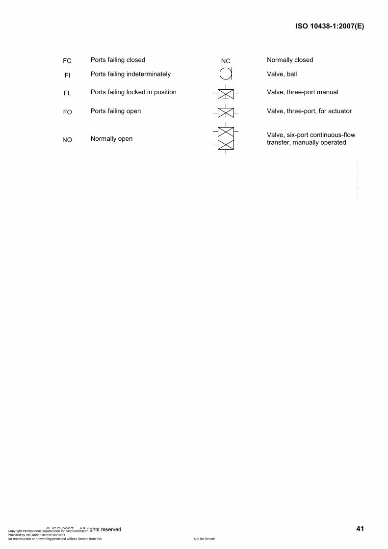
ISO 10438-1:2007(E)
© ISO 2007 – All rights reserved 41
Ports failing closed Normally closed
Ports failing indeterminately Valve, ball
Ports failing locked in position
Valve, three-port manual
Ports failing open
Valve, three-port, for actuator
Normally open
Valve, six-port continuous-flow transfer, manually operated
Copyright International Organization for Standardization Provided by IHS under license with ISO
Not for ResaleNo reproduction or networking permitted without license from IHS
--`,,```,,,,````-`-`,,`,,`,`,,`---

ISO 10438-1:2007(E)
42 © ISO 2007 – All rights reserved
Annex C (informative)
Vendor drawing and data requirements (VDDR)
Copyright International Organization for Standardization Provided by IHS under license with ISO
Not for ResaleNo reproduction or networking permitted without license from IHS
--`,,```,,,,````-`-`,,`,,`,`,,`---

Tabl
e C
.1 —
VD
DR
for g
ener
al- a
nd s
peci
al-p
urpo
se o
il-sy
stem
app
licat
ions
(see
text
for d
etai
ls o
f the
Des
crip
tion)
Job
No.
....
......
......
......
......
......
......
......
......
......
......
......
......
......
..Ite
m N
o. ..
......
......
......
......
......
......
......
......
......
......
......
......
......
.....
Pur
chas
e or
der N
o. ..
......
......
......
......
......
......
......
......
......
......
....
Dat
e ...
......
......
......
......
......
......
......
......
......
......
......
......
......
......
....
Req
uisi
tion
No.
....
......
......
......
......
......
......
......
......
......
......
......
..D
ate
......
......
......
......
......
......
......
......
......
......
......
......
......
......
......
. In
quiry
No.
....
......
......
......
......
......
......
......
......
......
......
......
......
...D
ate
......
......
......
......
......
......
......
......
......
......
......
......
......
......
......
. R
evis
ion
......
......
by
......
......
......
......
......
......
......
......
......
......
....
Con
sole
man
ufac
ture
r ...
......
......
......
......
......
......
......
......
......
......
Fo
r ...
......
......
......
......
......
......
......
......
......
......
......
......
......
......
....
Uni
t ....
......
......
......
......
......
......
......
......
......
......
......
......
......
......
....
Vend
or d
raw
ing
and
da
ta re
quire
men
ts
for g
ener
al- a
nd s
peci
al-p
urpo
se
oil-s
yste
m a
pplic
atio
ns
Site
....
......
......
......
......
......
......
......
......
......
......
......
......
......
......
..S
ervi
ce e .
......
......
......
......
......
......
......
......
......
......
......
......
......
......
Min
imum
requ
irem
ents
for g
ener
al-p
urpo
se s
yste
ms
indi
cate
d by
“Req
'd”.
d
Pro
posa
l a —
Bid
der s
hall
furn
ish
num
ber o
f pap
er c
opie
s/nu
mbe
r of e
lect
roni
c co
pies
of d
ata
as in
dica
ted
Rev
iew
— V
endo
r sha
ll fu
rnis
h nu
mbe
r of p
aper
cop
ies/
num
ber o
f ele
ctro
nic
copi
es o
f dat
a as
indi
cate
d
Fina
l — V
endo
r sha
ll fu
rnis
h nu
mbe
r of p
aper
cop
ies/
num
ber o
f ele
ctro
nic
copi
es o
f dat
a as
indi
cate
d
Dis
trib
utio
n re
cord
D
escr
iptio
n (s
ee fo
llow
ing
text
)
Rev
iew
du
e fro
m
vend
or b,
c
Rev
iew
re
ceiv
ed
from
ven
dor
Rev
iew
re
turn
ed to
vend
or
Fina
l du
e fro
m
vend
or c
Fina
l re
ceiv
ed
from
ven
dor
Req
'd
/ /
/ a)
C
ertif
ied
dim
ensi
onal
out
line
draw
ing
and
list o
f con
nect
ion
/ /
/ b)
C
ompo
nent
dra
win
gs a
nd b
ills o
f mat
eria
ls
N
/A
/ /
/ c)
S
yste
m s
chem
atic
and
bill
of m
ater
ials
, inc
ludi
ng c
ompo
nent
siz
ing
crite
ria
N
/A
/ /
/ d)
C
ompo
nent
dat
ashe
ets
R
eq'd
/
/ /
e)
Ele
ctric
al a
nd in
stru
men
tatio
n w
iring
dia
gram
and
bill
of m
ater
ials
/
/ /
f) E
lect
rical
and
inst
rum
enta
tion
term
inal
box
layo
ut a
nd li
st o
f con
nect
ions
/
/ /
g)
Con
sole
test
pro
cedu
re
N
/A
/ /
/ h)
W
eld
proc
edur
es
/ /
/ i)
Hyd
rost
atic
test
logs
/
/ /
j) O
pera
tiona
l tes
t log
s
N/A
/
/ /
k)
As-
built
dat
ashe
ets
R
eq'd
/
/ /
l) In
stal
latio
n, o
pera
ting
and
mai
nten
ance
man
uals
N/A
/
/ /
m)
Pro
gres
s re
ports
/
/ /
n)
Spa
re p
arts
reco
mm
enda
tion
and
pric
e lis
t
/
/ /
o)
Pre
ssur
e ve
ssel
cer
tific
atio
n da
ta
a
Pro
posa
l dra
win
gs a
nd d
ata
do n
ot h
ave
to b
e ce
rtifie
d. T
ypic
al d
ata
shal
l be
clea
rly id
entif
ied
as s
uch.
b
Pur
chas
er m
ay in
dica
te in
the
colu
mn
the
desi
red
time
fram
e fo
r sub
mis
sion
of d
ata.
c
Bid
der s
hall
com
plet
e th
ese
two
colu
mns
to re
flect
the
actu
al d
istri
butio
n sc
hedu
le a
nd in
clud
e th
is fo
rm w
ith t h
e pr
opos
al.
d N
/A s
igni
fies
an it
em is
gen
eral
ly n
ot a
pplic
able
to g
ener
al-p
urpo
se s
yste
ms.
e
Ser
vice
may
be
GP
lube
(GP
L), S
P lu
be (S
PL)
, SP
seal
(SP
S),
SP c
ombi
ned
lube
and
sea
l (SP
LS),
or s
elf-a
ctin
g ga
s s e
al m
odul
e (G
M).
ISO 10438-1:2007(E)
© ISO 2007 – All rights reserved 43Copyright International Organization for Standardization Provided by IHS under license with ISO
Not for ResaleNo reproduction or networking permitted without license from IHS
--`,,```,,,,````-`-`,,`,,`,`,,`---
ISO 10438-1:2007(E)
44 © ISO 2007 – All rights reserved
Details of each numbered item of the description list given in Table C.1 are as follows:
a) certified dimensional outline drawing and list of connections for oil or dry-gas support system, including the following:
⎯ size, rating and location of all customer connections;
⎯ approximate overall handling mass;
⎯ overall dimensions, maintenance clearances and dismantling clearances;
⎯ dimensions of baseplates from a fixed control point complete with diameter, number and locations of bolt holes; thickness of the metal through which it is necessary that the bolts pass and recommended clearance; centres of gravity; and details for foundation design;
b) component drawings and bills of materials for oil or dry-gas support system, including the following:
⎯ filter outline drawings;
⎯ cooler outline drawings (oil systems);
⎯ rundown tank and/or overhead seal tank outline drawings (oil systems);
⎯ instrumentation cut sheets with dimensions;
⎯ oil-pump outline drawings (oil systems);
⎯ oil-pump coupling drawings (oil systems);
c) system schematic and bill of materials, including component-sizing criteria for oil or dry-gas support system, which includes the following:
⎯ steady-state and transient flows and pressures at each use point;
⎯ control, alarm and trip settings (pressures, temperatures and flows as applicable);
⎯ supply temperatures and heat loads at each point at maximum load;
⎯ utility requirements, including electricity, steam, water and air;
⎯ pipe and valve sizes;
⎯ instrumentation, safety devices and control schemes;
d) individual component datasheets as applicable on the following:
⎯ pump datasheets;
⎯ filter datasheets;
⎯ cooler datasheets;
e) electrical and instrumentation wiring diagram and bill of materials; the schematics shall show all alarm and shutdown limits (set points);
f) electrical and instrumentation arrangement drawings, including terminal box layout and list of connections;
Copyright International Organization for Standardization Provided by IHS under license with ISO
Not for ResaleNo reproduction or networking permitted without license from IHS
--`,,```,,,,````-`-`,,`,,`,`,,`---
ISO 10438-1:2007(E)
© ISO 2007 – All rights reserved 45
g) console test procedures, including any special or optional tests to be performed;
h) welding procedures for fabrication and repair;
i) certified hydrostatic test logs;
j) operational test logs;
k) as-built datasheets;
l) installation, operating and maintenance manuals describing the following:
⎯ start-up;
⎯ normal shutdown;
⎯ emergency shutdown;
⎯ operating limits [see item e)];
⎯ oil recommendations and specifications;
⎯ routine operational procedures;
⎯ instructions for maintenance of purchased mechanical components such as pump, pump seals, etc.;
⎯ performance data, including flows, pressures, temperatures and heat loads;
⎯ as-built data, including datasheets [see item k)] and test logs.
m) progress reports and delivery schedule, including vendor buyouts and milestones; the reports shall include engineering, purchasing, manufacturing and testing schedules for all major components; planned and actual dates and the percentage completed shall be indicated for each milestone in the schedule;
n) spare parts list with stocking level recommendations;
o) pressure vessel certification data, including pressure vessel calculations, hydrotest reports and material mill test reports for filters, coolers and rundown tanks in the system.
Copyright International Organization for Standardization Provided by IHS under license with ISO
Not for ResaleNo reproduction or networking permitted without license from IHS
--`,,```,,,,````-`-`,,`,,`,`,,`---

ISO 10438-1:2007(E)
46 © ISO 2007 – All rights reserved
Annex D (informative)
Oil or gas filter performance and oil-system cleanliness testing
D.1 General considerations
This annex is intended to provide users of ISO 10438 (all parts) with information relative to oil or gas filter performance and oil-system cleanliness testing.
D.2 Filter specifications
D.2.1 General characteristics
The primary requirement of filtration is to reliably remove contaminates in a different phase from a liquid or gas stream. ISO 10438-2 describes filters necessary to remove from the oil particles that can be detrimental to special-purpose machine bearings, gears or oil seals over an extended operating period. ISO 10438-3 describes filters that are intended to remove sufficient solid particles from lubricating oil to provide an economical measure of protection for general-purpose equipment bearings and gears. ISO 10438-4 describes filters necessary to remove from the seal gas liquid-phase contaminants and particles that can be detrimental to a dry gas seal.
D.2.2 Filter element reliability
The filters shall be reliable, not fail or plug off during normal operation of the system and be able to retain contaminates during extreme upsets and even pulsating pressures. For this reason, it is necessary that filter elements for ISO 10438 systems be able to withstand high differentials without collapse or release of trapped particles. (See the other parts of ISO 10438 for specific allowable collapse pressures.)
D.2.3 Water contamination
A requirement has been added to ISO 10438-2 and ISO 10438-3 that the filters be water resistant up to a water content of 5 % at elevated temperatures to further assure filter element integrity. Water contamination of the oil can initiate the deterioration of some elements due to the incompatibility of the filter media with water at operating temperatures.
Elements can also absorb water and experience high differential pressures caused by the swelling of the filter medium. An optional requirement has been added for non-hydroscopic media that, over an extended exposure period, clean elements do not double their pressure drop. Users of oil systems for which water contamination can be a problem should consider non-hydroscopic filters. The user should keep in mind that water contamination should not persist on a routine basis. If water contamination is experienced, the source of the water should be determined and corrected. When correction is not feasible, a separate water-removal system or a slip stream filter/coalescer should be considered to keep the water contamination under control.
Water contamination can be a problem for an oil system serving a steam turbine. Other systems commonly exposed to water contamination include the following:
⎯ oil systems where make-up oil is provided from bulk storage or storage drums that are inadequately protected;
⎯ oil systems where the water pressure in the cooler(s) can exceed the oil pressure;
Copyright International Organization for Standardization Provided by IHS under license with ISO
Not for ResaleNo reproduction or networking permitted without license from IHS
--`,,```,,,,````-`-`,,`,,`,`,,`---

ISO 10438-1:2007(E)
© ISO 2007 – All rights reserved 47
⎯ oil systems located at humid sites, especially if the equipment served is in intermittent service and can also experience problems with water contamination.
D.2.4 Beta ratio
Of primary importance in the selection of filters for ISO 10438 (all parts) systems is the filter element micron size rating. In earlier standards, the requirement was 10 µm nominal rating. In a clarification note (see the third edition of API 614), nominal was implied to be 90 % efficient for 10 µm spherical particles and absolute was presumed for 15 µm particles for a 10 µm nominal rated element. The words “nominal” and “absolute” are not applied uniformly by vendors and there can be significant performance differences from one filter to another with 10 µm nominal filters.
It is more precise to rate filter elements by the beta ratio of the element for a given size particle and larger. The beta ratio expressed as βx W y, where x is the filter element rating, expressed in micrometres, and y is the ratio of particles x µm or larger entering a filter; divided by the number of particles x µm or larger exiting a filter.
EXAMPLE 1 Display a beta ratio of equal to or greater than 10 for a 10 µm rated filter: x = 10 µm; y W 10.
β10 W 10
EXAMPLE 2 Display a beta ratio of equal to or greater than 200 for a 25 µm rated filter: x = 25 µm; y W 200.
β25 W 200
In order to determine the particle-removal efficiency, EPR, expressed in percent, for a filter with a known beta ratio, use Equation (D.1):
( )PR 1 1 100E y⎡ ⎤⎢ ⎥⎣ ⎦
= − × (D.1)
For Example 1, where β10 W 10 and y W 10 for particles 10 µm and larger, the minimum EPR is calculated as
( )PR 110µm 1 10010E ⎡ ⎤⎛ ⎞⎢ ⎥⎜ ⎟
⎝ ⎠⎢ ⎥⎣ ⎦= − ×
( )PR 10µm 90 %E =
For Example 2, where β25 W 200 and y W 200 for particles 25 µm and larger, the minimum EPR is calculated as
( )PR 125µm 1 100200E ⎡ ⎤⎛ ⎞⎢ ⎥⎜ ⎟
⎝ ⎠⎢ ⎥⎣ ⎦= − ×
( )PR 25µm 99,5 %E =
For every type of filter element, a curve of the beta ratio plotted against the micron size can be developed. The position and shape of this curve is significantly affected by the construction features of the filter element. Some filter elements can have a very wide band of performance and others can have a narrow band. An example of a filter element, A, with a wide performance band can have a series of ratios β2 W 2, β10 W 10; β15 W 200 and a β25 W 1 000. Another filter element, B, with a narrower band can have a series of ratios β5 W 2; β10 W 10; and a β15 W 1 000.
In both examples A and B, the filter element is acceptable for special-purpose systems. The main issue is that the manufacturer of both A and B may give a different nominal rating. It is not until the beta ratio for a given micron size is greater than or equal to the specified beta ratio that the filter is acceptable.
Copyright International Organization for Standardization Provided by IHS under license with ISO
Not for ResaleNo reproduction or networking permitted without license from IHS
--`,,```,,,,````-`-`,,`,,`,`,,`---

ISO 10438-1:2007(E)
48 © ISO 2007 – All rights reserved
There are many factors in determining the performance of a filter on a range of particles. Factors such as pressure, flow differential pressure, particle size, particle shape, fluid and degree of loading can result in different beta ratios for the same type of element. There is a widely used standard hydraulic filter test that is relatively similar to the conditions encountered in API STD 614 lube and seal systems. For the purpose of ISO 10438-2 and ISO 10438-3, ISO 16889 or equal multi-pass-method type testing is required for passing the filter rating. A more detailed description of ISO 16889 testing is outlined in D.2.8.2. Filter vendors who supply type-tested elements have and can make available the test data for the elements being considered by ISO 10438-2 and ISO 10438-3.
D.2.5 Relative size of particles
In order to provide protection for equipment, it is necessary that the filter be able to remove particles that are in the range of the clearance of the component. For some insight into film thickness and particle sizes, see Tables D.1 and D.2. For the majority of systems covered by ISO 10438-2, ISO 10438-3 and ISO 10438-4, the filter ratings provide sufficient removal of the particles of concern as well as a reasonable installed life.
Based on the data presented in Tables D.1 and D.2, it can be tempting to use a finer filtration specification; but this can be inappropriate in many cases. Over-specification of the filter requirements can result in costly filter systems and frequent and expensive element changes.
Users of ISO 10438 filter specifications should be aware that filters remove particles smaller than the specified size. The filtration efficiency, EPR, or beta ratio, for 1 µm to 10 µm particles can be low, but some are captured by the element. It only takes more passes through the filter before the levels reach an equilibrium state where the filter removes the same number as ingress into the system. How small a particle below the specified size that be captured effectively is a function of the filter construction.
There are some exceptions where fine filtration can be necessary. These include, but are not limited to, control-oil systems with electrical-hydraulic pilot valves that have very close internal clearances and the oil-supply systems for high-speed gear-type couplings. In these applications, it can be appropriate to install separate duplex filter(s) in the branch stream(s) just ahead of the sensitive component(s). The EPR for these filters should be mutually agreed based on the requirements of the component.
Table D.1 — Relative size comparison of particles of some common materials
Particle size
µm Comparison
159 100 mesh screen opening
100 Table salt
74 200 mesh screen opening
60 Pollen
40 Lower limit of human vision
2 Bacteria
Copyright International Organization for Standardization Provided by IHS under license with ISO
Not for ResaleNo reproduction or networking permitted without license from IHS
--`,,```,,,,````-`-`,,`,,`,`,,`---
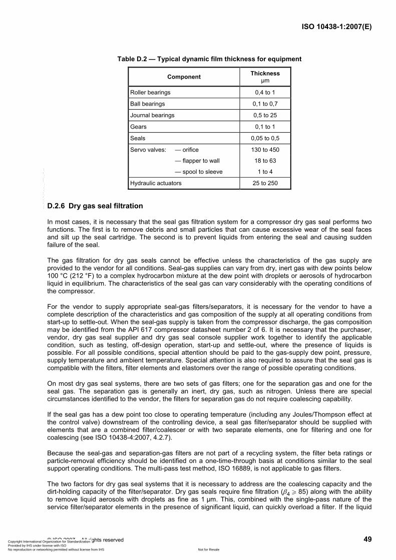
ISO 10438-1:2007(E)
© ISO 2007 – All rights reserved 49
Table D.2 — Typical dynamic film thickness for equipment
Component Thickness µm
Roller bearings 0,4 to 1
Ball bearings 0,1 to 0,7
Journal bearings 0,5 to 25
Gears 0,1 to 1
Seals 0,05 to 0,5
Servo valves: — orifice 130 to 450
— flapper to wall 18 to 63
— spool to sleeve 1 to 4
Hydraulic actuators 25 to 250
D.2.6 Dry gas seal filtration
In most cases, it is necessary that the seal gas filtration system for a compressor dry gas seal performs two functions. The first is to remove debris and small particles that can cause excessive wear of the seal faces and silt up the seal cartridge. The second is to prevent liquids from entering the seal and causing sudden failure of the seal.
The gas filtration for dry gas seals cannot be effective unless the characteristics of the gas supply are provided to the vendor for all conditions. Seal-gas supplies can vary from dry, inert gas with dew points below 100 °C (212 °F) to a complex hydrocarbon mixture at the dew point with droplets or aerosols of hydrocarbon liquid in equilibrium. The characteristics of the seal gas can vary considerably with the operating conditions of the compressor.
For the vendor to supply appropriate seal-gas filters/separators, it is necessary for the vendor to have a complete description of the characteristics and gas composition of the supply at all operating conditions from start-up to settle-out. When the seal-gas supply is taken from the compressor discharge, the gas composition may be identified from the API 617 compressor datasheet number 2 of 6. It is necessary that the purchaser, vendor, dry gas seal supplier and dry gas seal console supplier work together to identify the applicable condition, such as testing, off-design operation, start-up and settle-out, where the presence of liquids is possible. For all possible conditions, special attention should be paid to the gas-supply dew point, pressure, supply temperature and ambient temperature. Special attention is also required to assure that the seal gas is compatible with the filters, filter elements and elastomers over the range of possible operating conditions.
On most dry gas seal systems, there are two sets of gas filters; one for the separation gas and one for the seal gas. The separation gas is generally an inert, dry gas, such as nitrogen. Unless there are special circumstances identified to the vendor, the filters for separation gas do not require coalescing capability.
If the seal gas has a dew point too close to operating temperature (including any Joules/Thompson effect at the control valve) downstream of the controlling device, a seal gas filter/separator should be supplied with elements that are a combined filter/coalescer or with two separate elements, one for filtering and one for coalescing (see ISO 10438-4:2007, 4.2.7).
Because the seal-gas and separation-gas filters are not part of a recycling system, the filter beta ratings or particle-removal efficiency should be identified on a one-time-through basis at conditions similar to the seal support operating conditions. The multi-pass test method, ISO 16889, is not applicable to gas filters.
The two factors for dry gas seal systems that it is necessary to address are the coalescing capacity and the dirt-holding capacity of the filter/separator. Dry gas seals require fine filtration (β4 W 85) along with the ability to remove liquid aerosols with droplets as fine as 1 µm. This, combined with the single-pass nature of the service filter/separator elements in the presence of significant liquid, can quickly overload a filter. If the liquid
Copyright International Organization for Standardization Provided by IHS under license with ISO
Not for ResaleNo reproduction or networking permitted without license from IHS
--`,,```,,,,````-`-`,,`,,`,`,,`---

ISO 10438-1:2007(E)
50 © ISO 2007 – All rights reserved
rate to the filter/separator can exceed 50 % of the vendor's published capacity for a filter, a mechanical centrifugal separator ahead of the filter/separator is necessary to handle the liquid. The vendor's published separator capacity is based on steady-state liquid flow and new, clean elements. Excess capacity is necessary both to prevent overload of the separator as the element's time in service increases and to handle small, intermittent liquid slugs that can develop in horizontal pipe runs.
It is critical in services where the seal-gas dew points are close to the seal-gas flowing temperatures to trap any low points or slope all piping to a location where the liquids can be removed. This applies to both on- and off-skid seal gas piping.
The fine filter/separator elements can quickly plug off if the gas stream is contaminated with solid particles or sediment. If dirty gas is a problem, a guard filter with a large holding capacity can be necessary to obtain an acceptable filter/separator element life. Where practical, the element's dirt-holding capacity for a dry gas seal filter or filter/separator should be on the order of six months. For some “dirty” systems, the vendor and purchaser should review and agree on an acceptable filter-holding-capacity requirement based on what change-out frequency is possible and cost effective.
D.2.7 Filter-holding capacity
In most systems covered by ISO 10438-2 and ISO 10438-3, the ingress of contamination is not significant after the system is initially flushed. In general, filters that have sufficient flow capability to meet the requirements of ISO 10438-2:2007, 4.6.7, or ISO 10438-3:2007, 4.7.7 o), have an acceptable service life. The service life of filter elements in a system after flushing should be more than six months unless there is some problem external to the filters that is causing a significant degree of contamination.
D.2.8 Standards
D.2.8.1 General
A brief description of applicable filtration standards is outlined in D.2.8.2 to D.2.8.5 to provide the users of this part of ISO 10438 with some background on the basis for use of these standards. For more information, the actual standard should be reviewed.
D.2.8.2 ISO 16889
ISO 16889 specifies a rigorous method of type testing of filter elements in a recirculating loop with the injection of a standard test dust into the upstream side of the loop. Reporting of the results of the tests is in a standard format and the beta ratio for each of several micron sizes is averaged over the range from clean to maximum element differential pressure. This averaging is done over ten equal time increments. Typically, test data are taken for five particle-size ranges. The test is valid for 4 µm to at least 30 µm ratings and at flow rates in the test loop from 4 l/min to 600 l/min (1 gal/min to 160 gal/min). In addition to the filter-element average beta rating for five or more particle sizes, a contaminant loading capability for a filter element is established.
The following items are controlled during the test of a filter to assure consistent results.
a) The type of oil shall meet a given specification.
b) The temperature of the test fluid is controlled within a specific range.
c) The test contaminate is restricted to a known particle distribution and is standardized (ISO medium test dust).
d) An automatic particle counter is used and calibrated to a standard.
e) The automatic particle counter is used on-line and is validated to be correct in the system by means of a validation procedure.
f) A system volume-to-flow ratio is established.
Copyright International Organization for Standardization Provided by IHS under license with ISO
Not for ResaleNo reproduction or networking permitted without license from IHS
--`,,```,,,,````-`-`,,`,,`,`,,`---
ISO 10438-1:2007(E)
© ISO 2007 – All rights reserved 51
g) Testing condition variations are limited to flow, upstream contamination level on a mass basis, viscosity, temperature and system volume.
h) Instrument accuracy is established for the test circuit.
i) The injection system is validated to assure constant rates of contaminate injection.
The ISO 16889 test procedure provides a method to type test filter elements for lube-oil, control-oil and seal-oil systems in a loop that simulates as closely as possible conditions the element encounters in service. Filters used in ISO 10438-2 and ISO 10438-3 should have elements that have been type-tested to ISO 16889 or equivalent. The ISO 16889 test differential pressure should also be within the range of the expected operational differential pressure, since some types of elements can have significantly different beta ratios depending on the differential pressure range selected.
D.2.8.3 ISO 4406
ISO 4406 provides a means of defining the quantity of solid particle contaminates in oil or hydraulic fluid. The code is comprised of two scale numbers or grades based on the number of particles greater than or equal to 5 µm and 15 µm per millilitre of fluid. In recent years, many groups have expanded on the standard system to cover a third range for counts of particles 2 µm or larger. Particle counts are made using a microscope or by means of automatic particle counters. The results are reported as two or three grade numbers (see Table D.3 for a partial list of grade numbers) separated by a slash, “/”. The number for the smallest size range is presented first.
EXAMPLE 1 For a 1 ml sample with the following particle concentrations and grade numbers:
⎯ 58 000 particles W 2 µm: 23,
⎯ 4 100 particles u 5 µm: 19,
⎯ 210 particles u 15 µm: 15,
the grade for the sample is designated as ISO grade 23/19/15.
EXAMPLE 2 For a 10 ml sample with the following concentrations:
⎯ 4 100 particles W 5 µm,
⎯ 210 particles W15 µm,
the grades numbers are determined as
⎯ 4 100/1 = 410: 16,
⎯ 210/10 = 21: 12,
and the grade for the sample is designated as ISO grade 16/12.
Copyright International Organization for Standardization Provided by IHS under license with ISO
Not for ResaleNo reproduction or networking permitted without license from IHS
--`,,```,,,,````-`-`,,`,,`,`,,`---

ISO 10438-1:2007(E)
52 © ISO 2007 – All rights reserved
Table D.3 — ISO 4406 grade numbers
Number of particles per millilitre
n Grade number
80 000 < n u 160 000 24
40 000 < n u 80 000 23
20 000 < n u 40 000 22
10 000 < n u 20 000 21
5 000 < n u 10 000 20
2 500 < n u 5 000 19
1 300 < n u 2 500 18
640 < n u 1 300 17
320 < n u 640 16
160 < n u 320 15
80 < n u 160 14
40 < n u 80 13
20 < n u 40 12
10 < n u 20 11
5 < n u 10 10
2,5 < n u 5 9
1,3 < n u 2,5 8
0,64 < n u 1,3 7
0,32 < n u 0,64 6
0,16 < n u 0,32 5
0,08 < n u 0,16 4
0,04 < n u 0,08 3
0,02 < n u 0,04 2
0,01 < n u 0,02 1
D.2.8.4 SAE AS 4059E
SAE Aerospace Standard 4059E (which replaces NAS 1638) is another frequently used standard for assigning cleanliness. SAE AS 4059E defines 14 different cleanliness classes. The particle count basis is 100 ml of fluid. Each class specifies a given number of particles in each of five size groups: 5 µm to 15 µm, 15 µm to 25 µm, 25 µm to 50 µm, 50 µm to 100 µm and > 100 µm. Table D.4 is provided for reference.
Of the SAE AS 4059E and ISO 4406 standards, ISO 4406 is more frequently used. The reason the SAE class is referenced is that it can be estimated by filtering a measured sample of fluid through filter disc in a standard apparatus and making a comparison to standard comparator discs. This can be much more applicable in a field situation.
Copyright International Organization for Standardization Provided by IHS under license with ISO
Not for ResaleNo reproduction or networking permitted without license from IHS
--`,,```,,,,````-`-`,,`,,`,`,,`---
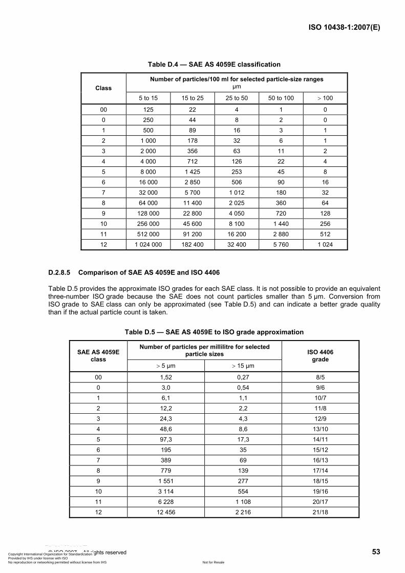
ISO 10438-1:2007(E)
© ISO 2007 – All rights reserved 53
Table D.4 — SAE AS 4059E classification
Number of particles/100 ml for selected particle-size ranges µm Class
5 to 15 15 to 25 25 to 50 50 to 100 > 100
00 125 22 4 1 0
0 250 44 8 2 0
1 500 89 16 3 1
2 1 000 178 32 6 1
3 2 000 356 63 11 2
4 4 000 712 126 22 4
5 8 000 1 425 253 45 8
6 16 000 2 850 506 90 16
7 32 000 5 700 1 012 180 32
8 64 000 11 400 2 025 360 64
9 128 000 22 800 4 050 720 128
10 256 000 45 600 8 100 1 440 256
11 512 000 91 200 16 200 2 880 512
12 1 024 000 182 400 32 400 5 760 1 024
D.2.8.5 Comparison of SAE AS 4059E and ISO 4406
Table D.5 provides the approximate ISO grades for each SAE class. It is not possible to provide an equivalent three-number ISO grade because the SAE does not count particles smaller than 5 µm. Conversion from ISO grade to SAE class can only be approximated (see Table D.5) and can indicate a better grade quality than if the actual particle count is taken.
Table D.5 — SAE AS 4059E to ISO grade approximation
Number of particles per millilitre for selected particle sizes SAE AS 4059E
class > 5 µm > 15 µm
ISO 4406 grade
00 1,52 0,27 8/5
0 3,0 0,54 9/6
1 6,1 1,1 10/7
2 12,2 2,2 11/8
3 24,3 4,3 12/9
4 48,6 8,6 13/10
5 97,3 17,3 14/11
6 195 35 15/12
7 389 69 16/13
8 779 139 17/14
9 1 551 277 18/15
10 3 114 554 19/16
11 6 228 1 108 20/17
12 12 456 2 216 21/18
Copyright International Organization for Standardization Provided by IHS under license with ISO
Not for ResaleNo reproduction or networking permitted without license from IHS
--`,,```,,,,````-`-`,,`,,`,`,,`---

ISO 10438-1:2007(E)
54 © ISO 2007 – All rights reserved
D.3 System cleanliness testing
D.3.1 General
The intent of the 100 mesh screen test for special-purpose lube and seal system consoles is to confirm that, when shipped, there is no debris remaining in the console or vendor-supplied piping or components that can contaminate the remainder of the system and extend system flushing time at the site. When applied by other standards to vendor testing of equipment or by users at machinery installation, it is intended to confirm there is no debris remaining in the system downstream of the filters that can be immediately detrimental to the machinery components served by the system(s).
D.3.2 Special-purpose systems
The method for determining when a special-purpose oil or seal-oil system is clean enough to deliver or when a vendor oil system is clean enough for factory-run testing of special-purpose machinery is covered by ISO 10438-2:2007, 7.3.3.9. This requirement may also be extended to a site evaluation of installed oil and seal-oil systems.
To comply with ISO 10438-2:2007, 7.3.3.9, systems that have been circulated for 1 h through the 100 mesh test screens shall have no more than the maximum particle counts shown in Table D.6.
Table D.6 — Maximum number of particles
DN NPS in
Schedule 40 or less Schedule 80 Schedule 160 Double
extra-strong
25 < 1 6 5 4 —
25 to 40 1 to 1,5 15 10 10 5
50 2 20 20 15 10
75 3 45 40 35 25
100 4 80 70 60 50
150 6 180 160 130 115
The use of test screens has been a reliable indicator of when an oil system with an adequate filter system can support start-up and/or testing of special-purpose machinery. The advantage of this testing is that a large representative volume of fluid is circulated through the test screens and the harmful debris that is introduced during fabrication and assembly of a special-purpose system is removed. When this test is done to an appropriate procedure and the test screens are located where there is downward flow through the screens in supply lines, the system will be free of damaging debris downstream of the screens.
There is some concern that 100 mesh screens do not pick up the small particles that can have undesirable long-term effects on the equipment serviced by the lube- and seal-oil system. The test specified in ISO 10438-2:2007, 7.3.3.9, is not intended to define how well a system performs in the long term. Long-term reliability of components served by a special-purpose system is more a function of the system design than filter specification. Other factors, such as control of the ingress of damaging size particles and the type of particle contamination, are important factors contributing to long-term reliability of machinery.
Some users of ISO 10438 have started to add a criterion from ISO 4406 or SAE AS 4059E to make sure the system is clean enough for long-term operation. The ISO 4406 grade specification often used is 20/15/12, (15/12 when only 5 µm and larger particles are counted). The approximate equivalent SAE requirement is Class 6. For some very critical or sensitive special-purpose machines, the ISO criterion may be as stringent as 18/14/11 (14/11 when particles smaller than 5 µm are not counted) downstream of the filters. This is approximately equivalent to SAE class 5. (See Table D.5.)
Copyright International Organization for Standardization Provided by IHS under license with ISO
Not for ResaleNo reproduction or networking permitted without license from IHS
--`,,```,,,,````-`-`,,`,,`,`,,`---

ISO 10438-1:2007(E)
© ISO 2007 – All rights reserved 55
In the context of factory testing large consoles with a large residence capacity, the use of a low particle count requirement, such as ISO grade 14/11, can result in extensive circulation through the filters before a sufficient number of passes through the filters have been completed to remove enough particles in the 5 µm to 10 µm range. This testing can be valid only after the screens have shown that the system is free of damaging debris at the equipment-supply connections. It is highly likely that the act of inspection of a console for debris of the console in accordance with ISO 10438-2:2007, 7.3.3.9, introduces enough dust to exceed the particle-count criteria. If not, the particle-count criteria will almost certainly be exceeded, due to even minor contamination that is inevitable in the course of special-purpose console and system preservation, shipping, storage and construction.
Caution should be used if only a particle-count criterion is specified for special-purpose systems/consoles in any context (console vendor, machinery test floor, at site operation). Because small volumes are sampled, the use of only particle-count criteria can easily miss damaging debris that can be released intermittently from piping and components.
Particle-count criteria can be useful in the course of flushing an entire system at the installation site when used in conjunction with testing the supply lines with 100 mesh screens. An ISO grade 15/12 criteria (SAE class 6) is acceptable for the start-up of most special-purpose equipment and even an ISO grade 16/13 criterion should not be a problem for start-up so long as particle counts are trending downward. In general, unless there is an equipment malfunction or a deficiency in the system filters, the system should be able to reach an ISO grade 14/11 (SAE class 5) level or better within a week or two of continuous service.
In general, users of special-purpose lube-oil and seal-oil systems who have tracked their systems by means of qualitative testing (e.g. using ISO 4406 or SAE AS 4059E) from installation through operation have noted at least one grade or class improvement from start-up of the system until a steady state particle level is reached.
D.3.3 General purpose
ISO 10438-3:2007, 7.3.3.8 b), requires 100 mesh screen testing of general-purpose oil consoles. This test is justified for relatively large general-purpose systems. The percent of the cost added for 100 mesh screen testing of large general-purpose systems is not large.
The alternate test specifies an ISO 4406 grade 17/14 or SAE class 8 be obtained as a method to verify whether the oil console is clean enough. It is necessary to select a circulation time to assure that there is mixing to suspend any sediments. Prior to taking a sample, it is suggested that the minimum circulation time be five times the reservoir capacity divided by the pump normal flow.
Some larger debris in the general-purpose oil console can be missed by checking only the particle count. If the oil is clean enough to pass ISO 4406 17/14 grade, then the quantity of debris left in the system should not require additional flushing effort at the site. At the site, prior to placing the system in service, it is still recommended that the entire system be flushed. A 100 mesh screen evaluation based on Table D.5 at the equipment oil-supply header should be done prior to commissioning the general-purpose equipment.
D.3.4 Dry gas seal console testing
Dry gas seal console cleanliness testing is covered by ISO 10438-4:2007, 7.3.3.3. This test is also based on inspection of a 100 mesh screen after the console is blown for a set period of time with 680 kPa (6,8 bar; 100 psig) dry and filtered air. The particle counting methods of SAE AS 4059E and ISO 4406 are not applicable to seal gas module testing because they are hydraulic tests. The use of a particle-count criterion is very difficult to set up in the context of a 10 min flow or blow test and is not normally required.
The cleanliness test procedure should be reviewed with the console fabricator. Whenever possible, the test screen should be located so that the gas flows down through the screen. The flow path through the console of the gas should be reviewed and it can be necessary to remove flow restrictions, such as orifice plates and control valve trim, for the test.
Copyright International Organization for Standardization Provided by IHS under license with ISO
Not for ResaleNo reproduction or networking permitted without license from IHS
--`,,```,,,,````-`-`,,`,,`,`,,`---

ISO 10438-1:2007(E)
56 © ISO 2007 – All rights reserved
The console filter/separator elements shall be removed if there is any possibility of reaching the collapse differential for the element or if the element can present a significant restriction to the flow of air. Removal of the console filter/separator elements should be done only after the upstream console piping and components are confirmed as being clean.
The location of the air source pressure gauge [680 kPa (6,8 bar; 100 psig) minimum] should be reviewed and it should always be downstream of the air supply filter. An agreement should be made with the vendor concerning whether or not the pressure can drop under flowing conditions and, if so, how large a drop is acceptable. It is also suggested that only one supply connection be checked at a time.
In the context of ISO 10438-4, this test is applicable to factory tests of consoles. With agreement of all parties, the use of this test can be expanded to include vendor test stand dry gas seal support consoles and the testing of the assembled dry gas seal support system in the field to determine if the system is clean enough to allow factory testing or field start-up.
Copyright International Organization for Standardization Provided by IHS under license with ISO
Not for ResaleNo reproduction or networking permitted without license from IHS
--`,,```,,,,````-`-`,,`,,`,`,,`---

ISO 10438-1:2007(E)
© ISO 2007 – All rights reserved 57
Annex E (informative)
International materials specifications
Table E.1 — International material specifications
USA International Europe Japan Material Class Applications
ASTM UNS ISO EN Grade Material No. JIS
Bolts and studs A193 Gr B7 G 41 400 2604-2-F31 EN 10269 42 Cr Mo 4
1.7225 JIS G4107 CI SNB7
Carbon steel
Nuts A194 Gr 2H K 04 002 683-1-C35e EN 10269 C 35 E 1.1181 JIS G4051 CI S45C
Stainless steel
Reservoirs (lube oil)
A240 Type 304
S30400 — — — — JIS G4304 SUS304
A312 TP 304
S30400 — — — — JIS G345 SUS304TP
A358 Grade 304
S30400 — — — — JIS G3468 SUS304TPY
A312 TP 316
S31600 — — — — JIS G3459 SUS316TP
Pipe 300 series
A358 Grade 316
S31600 — — — — JIS G3468 SUS316TPY
A403 CR 304
— — — — JIS G3459 SUS304TP
A105 — — — — JIS G4051 S25C
A182 — — — — JIS G3201
Pipe fitting
A234 — — — — —
Stainless steel
Flange A181
S30400
— — — — JIS G3214
Cu-Ni Admiralty metal seamless heat- exchanger tubing materials
B111 C44300
C44300 — EN 12451 CW706R
— — JIS H3300 C4430 T
Copyright International Organization for Standardization Provided by IHS under license with ISO
Not for ResaleNo reproduction or networking permitted without license from IHS
--`,,```,,,,````-`-`,,`,,`,`,,`---

ISO 10438-1:2007(E)
58 © ISO 2007 – All rights reserved
Annex F (informative)
Explanation of reservoir levels
F.1 The rundown level (key item 1 in Figure F.1) is the highest level that oil in the reservoir can reach when the entire system is shut down.
F.2 The maximum operating level (key item 2 in Figure F.1) is the highest level that oil can reach during normal operation of the equipment.
F.3 The minimum operating level (key item 3 in Figure F.1) is the lowest level that oil can reach during normal operation of the equipment.
F.4 The suction-loss level (key item 4 in Figure F.1) is the level above the pump suction level (key item 5 in Figure F.1) at which the pump begins to lose prime. The pump suction level is defined by the pump suction vortex and net positive suction head requirements.
F.5 The charge capacity is the total volume below the rundown level.
F.6 The normal operating range is any level between the maximum and minimum operating levels.
F.7 The retention capacity is the total volume below the minimum operating level.
F.8 Retention time is the time allowed for disengagement of entrained air or gas.
F.9 The rundown capacity is the volume between the rundown level and the maximum operating level.
F.10 The working capacity is the volume between the minimum operating level and the suction-loss level.
Copyright International Organization for Standardization Provided by IHS under license with ISO
Not for ResaleNo reproduction or networking permitted without license from IHS
--`,,```,,,,````-`-`,,`,,`,`,,`---

ISO 10438-1:2007(E)
© ISO 2007 – All rights reserved 59
Dimensions in millimetres (inches)
Key 1 rundown level 2 maximum operating level 3 minimum operating level 4 suction-loss level 5 pump suction level 6 manufacturer's standard glass length
a A manufacturer's standard gauge glass may be used in this arrangement with the bottom of the gauge no less than 50 mm below the minimum operating level and with any excess length being above maximum operating level. b Alternative pump suction arrangements.
Figure F.1 — Reservoir levels and oil level glass details
Copyright International Organization for Standardization Provided by IHS under license with ISO
Not for ResaleNo reproduction or networking permitted without license from IHS
--`,,```,,,,````-`-`,,`,,`,`,,`---
ISO 10438-1:2007(E)
60 © ISO 2007 – All rights reserved
Bibliography
[1] ISO 4406, Hydraulic fluid power — Fluids — Method for coding the level of contamination by solid particles
[2] ISO 16889, Hydraulic fluid power — Filters — Multi-pass method for evaluating filtration performance of a filter element
[3] ISO 7268, Pipe components — Definition of nominal pressure
[4] ISO 10438-2:2007, Petroleum, petrochemical and natural gas industries — Lubrication, shaft-sealing and control-oil systems and auxiliaries — Part 2: Special-purpose oil systems
[5] ISO 10438-3:2007, Petroleum, petrochemical and natural gas industries — Lubrication, shaft-sealing and control-oil systems and auxiliaries — Part 3: General-purpose oil systems
[6] ISO 10438-4:2007, Petroleum, petrochemical and natural gas industries — Lubrication, shaft-sealing and control-oil systems and auxiliaries — Part 4: Self-acting gas seal support systems
[7] ANSI/API 594, Check Valves: Wafer, Wafer-Lug, and Double Flanged Type
[8] ANSI/API 600, Bolted Bonnet Steel Gate Valves for Petroleum and Natural Gas Industries — Modified National Adoption of ISO 10434:1998
[9] API STD 602, Steel Gate, Globe and Check Valves for Sizes DN 100 and Smaller for the Petroleum and Natural Gas Industries
[10] API STD 614, Lubrication, Shaft-Sealing, and Control-Oil Systems for Special-Purpose Applications
[11] ANSI/API 660, Shell-and-Tube Heat Exchangers
[12] ANSI/API 661, Air-Cooled Heat Exchangers for General Refinery Services
[13] ANSI/ASME B1.20.1, Pipe Threads, General Purpose (Inch)
[14] ANSI/ASME B31.3-06, Process Piping
[15] ASTM A105/A105M, Standard Specification for Carbon Steel Forgings for Piping Applications
[16] ASTM A106/A106M, Standard Specification for Seamless Carbon Steel Pipe for High-Temperature Service
[17] ASTM A182/A182M, Standard Specification for Forged or Rolled Alloy and Stainless Steel Pipe Flanges, Forged Fittings, and Valves and Parts for High-Temperature Service
[18] ASTM A269, Standard Specification for Seamless and Welded Austenitic Stainless Steel Tubing for General Service
[19] ASTM A312/A312M, Standard Specification for Seamless, Welded, and Heavily Cold Worked Austenitic Stainless Steel Pipes
[20] ASTM A403/A403M, Standard Specification for Wrought Austenitic Stainless Steel Piping Fittings
[21] IEC 61511 (all parts), Functional safety — Safety instrumented systems for the process industry sector
[22] NAS 1638, Cleanliness requirements of parts used in hydraulic systems. (Replaced by SAE AS 4059E)
Copyright International Organization for Standardization Provided by IHS under license with ISO
Not for ResaleNo reproduction or networking permitted without license from IHS
--`,,```,,,,````-`-`,,`,,`,`,,`---

ISO 10438-1:2007(E)
© ISO 2007 – All rights reserved 61
[23] NFPA 70:2007, National Electrical Code
[24] SAE AS 4059E, Aerospace Fluid Power — Cleanliness Classification for Hydraulic Fluids
[25] ASTM E1003, Standard Test Method for Hydrostatic Leak Testing
[26] ASTM A181/A181M, Standard Specification for Carbon Steel Forgings, for General-Purpose Piping
[27] API RP 578, Material verification Program for New and Existing Alloy Piping Systems
[28] API STD 617, Axial and Centrifugal Compressors and Expander-compressors for Petroleum, Chemical and Gas Industry Service
[29] CEN/TR 14549, Guide to the use of ISO 15649 and ANSI/ASME B31.3 for piping in Europe in compliance with the Pressure Equipment Directive
Copyright International Organization for Standardization Provided by IHS under license with ISO
Not for ResaleNo reproduction or networking permitted without license from IHS
--`,,```,,,,````-`-`,,`,,`,`,,`---

ISO 10438-1:2007(E)
ICS 75.180.20 Price based on 61 pages
© ISO 2007 – All rights reserved
Copyright International Organization for Standardization Provided by IHS under license with ISO
Not for ResaleNo reproduction or networking permitted without license from IHS
--`,,```,,,,````-`-`,,`,,`,`,,`---