international journal of applied energy systems, vol. 1
TRANSCRIPT

Determination of Partial Discharge Severity in
Power Transformers Based on the Starting
Decomposing Material
Sherif S.M. Ghoneim Faculty of Industrial Education,
Suez University , Egypt
Sobhy. S. Dessouky Faculty of Engineering,
Port Said University , Egypt
Adel A. Elfaraskoury Laboratories& Researches and Tests,
Egyptian Electricity Holding Company
Cairo, Egypt
Ramy. N. R. Ghaly Mataria Technical College in Cairo
Ministry of Higher Education
Cairo, Egypt
Abstract— Dissolved gas analysis (DGA) is a common technique
to identify the transformer faults. The transformer faults are
identified based on the concentration of the combustible gases
such as Hydrogen (H2), Methane (CH4), Ethan (C2H6), Ethylene
(C2H4), Acetylene (C2H2), and Carbon mono-oxide (CO) in
addition to the ratios between these gases. On the other hand, the
DGA technique identifies only the transformer fault type not the
severity of this fault. In this paper, three objectives should be
achieved, the first one is determining the transformer fault type
based on the Duval triangle rules using a Fuzzy Logic model and
secondly, determining the partial discharge severity based on a
thermodynamic approach based on the starting decomposing
materials (n-Octane (C8H18) and Eicosane (C20H42)), thirdly,
comparing the severity of the partial discharge based on the type
of the starting decomposing material. The results indicate that
the severity of the partial discharge influenced by the type of
starting decomposing material.
Keywords—Partial discharge, power transformer, dissolved gas
analysis, insulating oil.
I. INTRODUCTION
A power transformer is one of the most important parts in the power network so its reliable operation is necessary. Early stage detection of transformer faults avoided a catastrophic damage and unwanted outage of the transformer from the network [1]. Most of the transformer faults were developed in the insulation systems, which consists of the insulating oil and paper. Due to electrical, thermal and mechanical stresses, the insulation oils degraded and decomposed. The decomposing of the insulation oil generated dissolved gases, which were categorized to combustible and incombustible gases. These gases are Hydrogen (H2), Methane (CH4), Ethan (C2H6), Ethylene (C2H4), Acetylene (C2H2), and Carbon mono-oxide (CO). These Hydrocarbon gases are combustible gases and the energy required to form these gases increases in the order CH4 < C2H6 <=CO <=C2H4 <=H2<< C2H2. There were several DGA techniques, such as Dornenburg method, Rogers’ method, Key
gas method, Interational Electro-technical Commission (IEC) standard code, and graphical representation method (triangle and pentagon), which were used to diagnose the transformer faults [1-4]. Recently, artificial intelligent techniques are merged with the previous DGA techniques to enhance the diagnostic accuracy [1, 5-13]. In spite of the ability of DGA techniques to detect the transformer faults, they can’t monitor the severity of these faults [14].
The conventional DGA techniques such as Dornenburg ratio method, Rogers ratio method and IEC standard code were based on the ratios between main five combustible gases such as Hydrogen (H2), Methane (CH4), Ethan (C2H6), Ethylene (C2H4), Acetylene (C2H2). For Dornenburg ratio method, the ratios are CH4/H2, C2H2/C2H4, C2H2/CH4 and C2H6/C2H2. For Rogers four ratio method, the ratios are CH4/H2, C2H2/C2H4, C2H4/C2H6 and C2H6/CH4. For IEC Standard code, the ratios were CH4/H2, C2H2/C2H4 and C2H4/ C2H6. The previous methods have poor accuracy for detecting transformer faults and in some conditions, it fails to interpret the transformer fault type. The Duval triangle is one of the conventional DGA methods and it is stable and reliable for many years and its common population DGA method all over the world. It depends on percentage of three combustible gases only which are Methane (CH4), Ethylene (C2H4), Acetylene (C2H2) to their sum. All of these conventional methods were addressed in detail in [1].
The total dissolved combustible gases (TDCG) were used as an indication of the severity of the transformer conditions accordingly the maintenance actions are addressed [2, 15]. The TDCG which is the sum of all combustible gases is not sufficient to determine the fault severity since it did not take into account which gas rate was varied. The impact of the energy weighted of the dissolved gases was addressed in [16] that to evaluate the severity of transformer faults. The proposed Artificial Neural Network (ANN) model based on the rules of Duval triangle was built to identify the transformer fault and used n-octane as a starting decomposing material to determine
47
International Journal of Applied Energy Systems, Vol. 1, No. 2, July 2019
the transformer fault severity [3]. On the other hand, Eicosane was used as a starting decomposing material to investigate the severity of the transformer fault [17]. The diagnostic fault model was constructed based on the rules of IEC standard code.
An Eicosane and n-octane were two starting decomposing material, which were used in the thermodynamic approach to estimate the severity of the transformer fault [14-17]. In this paper, the impact of the starting decamping material (Eicosane and n-octane) to determine the partial discharge severity was addressed. This comparative study was an evidence to explain that the variation of the starting decomposing materials led to a variation of the partial discharge fault severity. The constructed model to identify the partial discharge fault severity was based on the Duval triangle method, where the fault type was determined using a fuzzy logic system based on Duval triangle fault region rules. The results are based on random selected samples demonstrated that the partial discharge severity is medium with Eicosane and low severity with n-octane. For the emergency condition, the maintenance process should take into consideration the results based on Eicosane.
II. DGA BASED ON THE DUVAL TRIANGLE METHOD
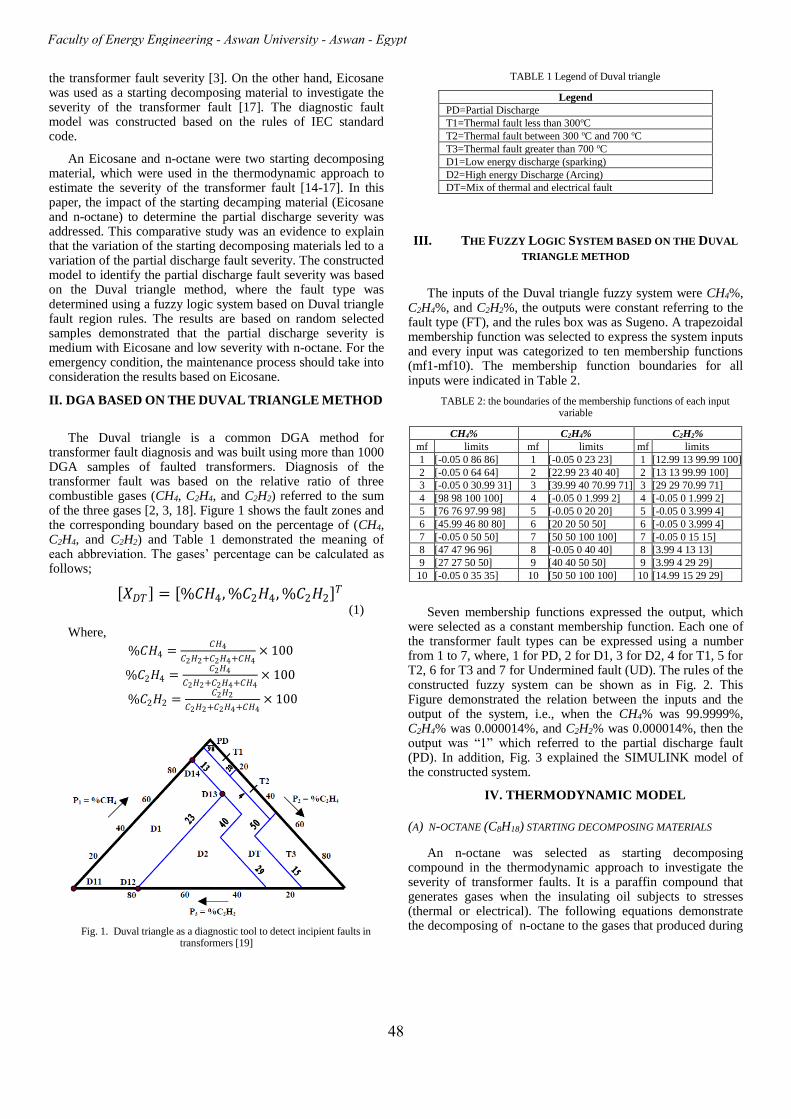
The Duval triangle is a common DGA method for transformer fault diagnosis and was built using more than 1000 DGA samples of faulted transformers. Diagnosis of the transformer fault was based on the relative ratio of three combustible gases (CH4, C2H4, and C2H2) referred to the sum of the three gases [2, 3, 18]. Figure 1 shows the fault zones and the corresponding boundary based on the percentage of (CH4, C2H4, and C2H2) and Table 1 demonstrated the meaning of each abbreviation. The gases’ percentage can be calculated as follows;
𝑋𝐷𝑇 = %𝐶𝐻4, %𝐶2𝐻4, %𝐶2𝐻2 𝑇
(1)
Where,
%𝐶𝐻4 =𝐶𝐻4
𝐶2𝐻2+𝐶2𝐻4+𝐶𝐻4× 100
%𝐶2𝐻4 =𝐶2𝐻4
𝐶2𝐻2+𝐶2𝐻4+𝐶𝐻4× 100
%𝐶2𝐻2 =𝐶2𝐻2
𝐶2𝐻2+𝐶2𝐻4+𝐶𝐻4× 100
Fig. 1. Duval triangle as a diagnostic tool to detect incipient faults in transformers [19]
TABLE 1 Legend of Duval triangle
Legend
PD=Partial Discharge
T1=Thermal fault less than 300oC
T2=Thermal fault between 300 oC and 700 oC
T3=Thermal fault greater than 700 oC
D1=Low energy discharge (sparking)
D2=High energy Discharge (Arcing)
DT=Mix of thermal and electrical fault
III. THE FUZZY LOGIC SYSTEM BASED ON THE DUVAL
TRIANGLE METHOD
The inputs of the Duval triangle fuzzy system were CH4%, C2H4%, and C2H2%, the outputs were constant referring to the fault type (FT), and the rules box was as Sugeno. A trapezoidal membership function was selected to express the system inputs and every input was categorized to ten membership functions (mf1-mf10). The membership function boundaries for all inputs were indicated in Table 2.
TABLE 2: the boundaries of the membership functions of each input variable
CH4% C2H4% C2H2%
mf limits mf limits mf limits
1 [-0.05 0 86 86] 1 [-0.05 0 23 23] 1 [12.99 13 99.99 100]
2 [-0.05 0 64 64] 2 [22.99 23 40 40] 2 [13 13 99.99 100]
3 [-0.05 0 30.99 31] 3 [39.99 40 70.99 71] 3 [29 29 70.99 71]
4 [98 98 100 100] 4 [-0.05 0 1.999 2] 4 [-0.05 0 1.999 2]
5 [76 76 97.99 98] 5 [-0.05 0 20 20] 5 [-0.05 0 3.999 4]
6 [45.99 46 80 80] 6 [20 20 50 50] 6 [-0.05 0 3.999 4]
7 [-0.05 0 50 50] 7 [50 50 100 100] 7 [-0.05 0 15 15]
8 [47 47 96 96] 8 [-0.05 0 40 40] 8 [3.99 4 13 13]
9 [27 27 50 50] 9 [40 40 50 50] 9 [3.99 4 29 29]
10 [-0.05 0 35 35] 10 [50 50 100 100] 10 [14.99 15 29 29]
Seven membership functions expressed the output, which were selected as a constant membership function. Each one of the transformer fault types can be expressed using a number from 1 to 7, where, 1 for PD, 2 for D1, 3 for D2, 4 for T1, 5 for T2, 6 for T3 and 7 for Undermined fault (UD). The rules of the constructed fuzzy system can be shown as in Fig. 2. This Figure demonstrated the relation between the inputs and the output of the system, i.e., when the CH4% was 99.9999%, C2H4% was 0.000014%, and C2H2% was 0.000014%, then the output was “1” which referred to the partial discharge fault (PD). In addition, Fig. 3 explained the SIMULINK model of the constructed system.
IV. THERMODYNAMIC MODEL
(A) N-OCTANE (C8H18) STARTING DECOMPOSING MATERIALS
An n-octane was selected as starting decomposing compound in the thermodynamic approach to investigate the severity of transformer faults. It is a paraffin compound that generates gases when the insulating oil subjects to stresses (thermal or electrical). The following equations demonstrate the decomposing of n-octane to the gases that produced during
48
Faculty of Energy Engineering - Aswan University - Aswan - Egypt

stresses on the transformer oil such as H2, CH4, C2H6, C2H4, and C2H2 [14-15];
( ) ( ) ( ) lHC gCHlHC 1474188 += (2.a)
( ) ( ) ( ) lHC gHClHC 12662188 += (2.b)
( ) ( ) ( ) lHC gHClHC 14642188 +=
(2.c)
( ) ( ) ( ) lHC gHlHC 1682188 +=
(2.d) ( ) ( ) ( ) ( ) lHCgH gHClHC 146222188 ++=
(2.e) where, “g” refers to gas state and “l” refers to liquid state.
The thermodynamic model based in n-octane can be illustrated as follows;
• The hydrocarbon decomposing is an endothermic reaction, and then absorbs energy from the surroundings.
• The enthalpy change expresses the heat content of each reaction.
The enthalpy of reaction (Hreaction) is the difference between
the enthalpy of the formation of the products (Hof)p and the
enthalpy of the formation of the reactants (Hf)R which refers
to the enthalpy of formation of the fault gases.
Fig. 2. The diagram illustrated the rules of the constructed fuzzy system
Fig. 3. The SIMULINK model of the proposed algorithm
After computing the reaction of formation of the fault gases,
the energy weighted factor can be determined by taking the
enthalpy of reaction of Methane (CH4) as a reference as
follows;
The enthalpy change of reaction can be calculated as (3); o
reactants f,o
products f,oreaction HH H −=
(3)
where, (Hof) is the enthalpy of formation, therefore, a sample
calculation of the (Horeaction) for reaction (2.a) is as follows;
( ) ( )147of4
of
oproducts f, HC HCH H H +=
(4)
The standard enthalpies of the formation CH4 and C7H14 were
shown as in Table 3 and were substituted in (4).
Hence,
∆𝐻𝑓 ,𝑝𝑟𝑜𝑑𝑢𝑐𝑡𝑠𝑜 = −74.9 − 97.7 = −172.6 𝑘𝐽/𝑚𝑜𝑙 (5)
The standard enthalpy of the reactants is estimated by,
∆𝐻𝑓 ,𝑟𝑒𝑎𝑐𝑡𝑎𝑛𝑡𝑠𝑜 = ∆𝐻𝑓
𝑜 𝐶8𝐻18 = −250.3𝑘𝐽
𝑚𝑜𝑙 (6)
Therefore, the enthalpy change of reaction (Horeaction) for
CH4 can be calculated based on (3) by,
∆𝐻𝑟𝑒𝑎𝑐𝑡𝑖𝑜𝑛𝑜 𝐶𝐻4 = ∆𝐻𝑓 ,𝑝𝑟𝑜𝑑𝑢𝑐𝑡𝑠
𝑜 − ∆𝐻𝑓 ,𝑟𝑒𝑎𝑐𝑡𝑎𝑛𝑡𝑠𝑜 =
−172.6— (−250.3) = 77.7 𝑘𝐽/𝑚𝑜𝑙 (7)
TABLE 3 Enhalpy of formation for each product of n-octane (C8H18)
decomposing reactions at 298oK and 105 KPA [15]
molecule Hof molecule Ho
f
C8H18 (l) -250.3 CH4(g) -74.9
C7H14 (l) -97.7 C2H6(g) -83.8
C6H14 (l) -198.7 C2H4(g) 52.5
C6H12 (l) -73 C2H2(g) 226.7
C8H16 (l) -121.8 H2(g) 0
By the same manner, the other n-octane product gases can
be computed as in Table 4 based on the enthalpy change of the
formation for each gas and liquid product as in Table 3.
Therefore, the relative energy factor (REF) for each gas can be
calculated as in Table 4;
The energy weighted based on the five gases (H2, CH4,
C2H6, C2H4, and C2H2) for the n-octane gas product can be
calculated as in (8);
52242342
26214
REF)HC(CREF)H(CREF)HC(C
REF)HC(CREF)CH(C)HMEEA(ghtedEnergy wei
+++
+= (8)
The abbreviation (HMEEA) refers to Hydrogen, Methane,
Ethan, ethylene, and Acetylene.
TABLE 4 Enthalpy of reaction for each gas that was produced from n-octane
decomposing [14-15]
Product
gas
(Hof)Reactant
s (Ho
f)Products (Ho
reaction)
as in (5) REF
CH4 -250.3 -172.6 77.7 REF1 77.7/77.7=1.00
C2H6 -250.3 -156.8 93.5 REF2 93.5/77.7=1.20
C2H4 -250.3 -146.2 104.1 REF3 104.1/77.7=1.34
H2 -250.3 -121.8 128.5 REF4 128.5/77.7=1.65
C2H2 -250.3 28.0 278.3 REF5 278.3/77.7=3.58
(B) EICOSANE (C20H42) STARTING DECOMPOSING MATERIAL
A n-octane consists of paraffin molecules which were not
stable and removed from the crude oil during its production
49
International Journal of Applied Energy Systems, Vol. 1, No. 2, July 2019

process and hence, the energy required for cracking reaction to
generate n-octane can be neglected. Due to n-octane kept in
the fault zone for a long time to achieve the equilibrium state,
therefore, it considered a great issue [15]. Hence, the Eicosane
(C20H42) was proposed to construct the thermodynamic model
to identify the severity of the transformer faults based on
DGA. Equations 9a to 9b, demonstrate the reaction to produce
the combustible gases that was used in the thermodynamic
approach as follows [17];
( ) ( ) ( ) lHC gCHlHC 381944220 += (9.a)
( ) ( ) ( ) lHC gHClHC 3618624220 += (9.b)
( ) ( ) ( ) lHC gHClHC 3818424220 += (9.c)
( ) ( ) ( ) lHC gHlHC 402024220 += (9.d)
( ) ( ) ( ) ( ) lHCgH gHClHC 38182224220 ++= (9.e)
Table 5 shows the enthalpy change of formation of each
product of the Eicosane (C20H42). Based on the magnitude of
the enthalpy change of formation of each Eicosane product as
in Table 5, the enthalpy change of the reaction of the gas
product can be calculated as in Table 6. In order to calculate
the energy weighted required to develop the gas product from
Eicosane equation (8) was applied.
TABLE 5 Enthalpy of formation for each product of Eicosane (C20H42)
decomposing reactions at 298oK and 105 KPA [17]
molecule Hof molecule Ho
f
C20H42 (l) -455.8 CH4(g) -74.9
C20H40 (l) -357.9 C2H6(g) -83.8
C19H38 (l) -345.9 C2H4(g) 52.5
C18H38 (l) -414.6 C2H2(g) 226.7
C18H36 (l) -314.1 H2(g) 0
TABLE 6 Enthalpy of reaction for each gas that was produced from Eicosane
decomposing [17]
Product
gas (Ho
f)Reactants (Hof)Products
(Horeaction) as
in (5) REF
CH4 -455.8 -420.8 35 REF1 35/35=1
C2H6 -455.8 -397.9 57.9 REF2 57.9/35=1.65
C2H4 -455.8 -362.1 93.7 REF3 93.7/35=2.68
H2 -455.8 -357.9 97.9 REF4 97.9/35=2.8
C2H2 -455.8 -187.9 267.9 REF5 267.9/35=7.65
V. SEVERITY OF THE PARTIAL DISCHARGE
The severity of the partial discharge is investigated based
on the variation of the starting decomposing material (n-
octane and Eicosane). The magnitude of partial discharge is
not sufficient to assess the life expectancy of the insulation.
Hence, additional information was required to estimate the
severity of the partial discharge. This information is the
energy that was associated with the decomposing process of
the insulating oils due to different stresses like electrical,
thermal, and mechanical stresses. Based on equation (8), the
energy weighted of the main five gases (H2, CH4, C2H6, C2H4,
and C2H2) can be calculated for n-octane and Eicosane and
then the relative ratio between the energy weighted of the five
gases and its total concentration can be computed as follows;
EWRO=Energy weighted HMEEA for n-octane/HMEEA
concentration (10)
Where, EWRO refers to the Energy weighted ratio of n-octane.
EWRE=Energy weighted HMEEA for Eicosane/HMEEA
concentration (11)
Where, EWRE refers to the Energy weighted ratio for
Eicosane.
According to the equations (10) and (11), the energy
weighted ratios for n-octane and Eicosane (EWRO and
EWRE) were computed. The magnitude of the EWRO and
EWRE ranged from 0 to 8. The low PD severity was
considered when EWRO and EWRE were less than or equal 2,
moderate when EWRO and EWRE were greater than 2 and
less than or equal 4 and the severity was high when EWRO
and EWRE were greater than 4 [14].
Although the rules for detecting the transformer fault
using Duval triangle DGA technique were based on only three
gases (CH4, C2H4, and C2H2), the accuracy of the Duval
triangle to detect partial discharge fault is poor. This fact is
due to the importance of H2 concentration in partial discharge
fault detection. Hence, the concentration of H2 as well as C2H6
was taken into account for computing the energy weighting
ratio with three other gases for the Duval triangle method. The
relative energy factor (REF) for each gas based on the starting
decomposing material was explained in Tables 4 and 6.
Table 7 explains the cases under considerations and contains
15th columns, column 1 refers to the case number, and the next
five columns indicated the concentration of H2, CH4, C2H6,
C2H4, and C2H2 in ppm. The ACT column expresses the actual
fault of each case and “1” refers to a partial discharge fault
and “4” to the low thermal fault. The eighth, ninth, and tenth
columns explained the percentage of CH4, C2H4 and C2H2
referred to the sum of them as in (1). Eleventh and twelfth
columns refer to the energy weighted ration for n-octane and
Eicosane (EWRO and EWRE) respectively. The DIG column
indicates the Duval triangle method diagnosis, which agrees
with the actual fault of all samples referring to the accuracy of
Duval triangle for detecting the fault type (100%). The last
two columns (SEV_E and SEV_O) illustrate the severity of the
partial discharge fault based on the magnitude of EWRE and
EWRO. When the severity using n-octane and Eicosane is 1, it
refers to low severity and when it is 2, it refers to medium
severity, on the other hand, 3 refers to high fault severity.
The severity based on EWRO and EWRE is different for all
studied cases As in case number 7, when the CH4% was
99.99996%, C2H4% was 0.000004%, and C2H2% was
0.000004%, and then the output was “1” which referred to the
partial discharge fault (PD), and the severity based on EWRE
(SEV_E) refers to 2 (medium severity) and the severity based
on EWRO (SEV_O) refers to 1 (low severity). Therefore,
based on the results of Table 7 the decomposing starting
material has a significant effect in determining the severity of
the partial discharge fault. For emergency monitoring of the
fault severity based on the starting decomposing material, the
severity results based Eicosane must be taken into
consideration rather than that based on n-octane.
50
Faculty of Energy Engineering - Aswan University - Aswan - Egypt

TABLE 7 The cases to investigate the severity based on the starting decomposing material
Case H2 CH4 C2H6 C2H4 C2H2 ACT CH4% C2H4% C2H2% EWRE EWRO DIG SEV_E SEV_O
1 110 7 <0.01 <0.01 <0.01 1 100 0.000014 0.000014 2.65 1.61 1 2 1
2 134 13 156 <0.01 <0.01 1 100 0.000008 0.000008 2.10 1.39 1 2 1
3 1458 9 1812 <0.01 <0.01 1 100 0.000011 0.000011 2.13 1.4 1 2 1
4 195 5.3 <0.01 <0.01 <0.01 1 100 0.000019 0.000019 2.71 1.63 1 2 1
5 109 16 <0.01 <0.01 <0.01 1 100 0.000006 0.000006 2.53 1.57 1 2 1
6 100 18 <0.01 <0.01 <0.01 1 100 0.000006 0.000006 2.49 1.55 1 2 1
7 160 24.7 38.5 <0.01 <0.01 1 100 0.000004 0.000004 2.37 1.50 1 2 1
8 187 5 1 <0.01 <0.01 1 100 0.00002 0.00002 2.7 1.63 1 2 1
9 121 3 1 <0.01 <0.01 1 100 0.000033 0.000033 2.7 1.63 1 2 1
10 32930 2397 157 <0.01 <0.01 1 100 0 0 2.64 1.60 1 2 1
11 37800 1740 249 8 8 1 99.1 0.455581 0.455581 2.68 1.62 1 2 1
12 8266 1061 22 <0.01 <0.01 1 100 0 0 2.56 1.58 1 2 1
13 9340 995 60 6 7 1 98.7 0.595238 0.694444 2.59 1.59 1 2 1
14 36036 4704 554 5 10 1 99.7 0.105955 0.211909 2.55 1.57 1 2 1
15 33046 619 58 2 <0.01 1 99.7 0.322061 0 2.73 1.64 1 2 1
16 40280 1069 1060 1 1 1 99.8 0.093371 0.093371 2.69 1.62 1 2 1
17 26788 18342 2111 27 <0.01 1 99.9 0.146987 0 2.03 1.38 1 2 1
18 92600 10200 <0.01 <0.01 <0.01 1 100 0 0 2.59 1.59 1 2 1
19 16000 3600 670 14 <0.01 1 99.6 0.387382 0 2.41 1.52 1 2 1
20 2091 149 20 3 <0.01 1 98.0 1.973684 0.000001 2.63 1.60 1 2 1
VI. CONCLUSIONS
The Duval triangle method identifies only the transformer
fault, but it can’t determine the severity of the fault. Therefore,
the thermodynamic approach is used to evaluate the severity of
the fault. There are two starting decomposing material that are
found in literature and the work tries to answer the question “Is
the severity of the fault changed when the starting decomposing
material changes?”. The results of this work demonstrated that
the severity of the partial discharge fault in the transformer can
be varied with the variability of the starting decomposing
material. Based on the results, all of random selected cases had
different partial discharge severity when using n-octane and
Eicosane. Therefore, the starting decomposing material that was
used in the thermodynamic approach had a significant effect in
determining the severity of the partial discharge fault.
REFERENCES [1]. S. Ghoneim, I. Taha, N.I. Elkalashy, “Integrated ANN-based
proactive fault diagnostic scheme for power transformers using dissolved gas analysis”, IEEE Transactions on Dielectrics and Electrical Insulation, 23, (3), pp. 1838–1845, 2016.
[2]. IEEE Standard C57.104-2008: ‘IEEE guide for the interpretation of gases generated in oil-immersed transformers’, February 2009.
[3]. M. Duval, A. dePablo, “Interpretation of gas-in-oil analysis using new IEC publication 60599 and IEC TC 10 databases”, IEEE Electrical Insulation Magazine, 17, (2), pp. 31–41, 2001.
[4]. IEC Publication 599, “Interpretation of the analysis of gases in transformers and other oil-filled electrical equipment in service,” First Edition 1978.
[5]. I. Taha, S.Ghoneim, H.G. Zaini, “A fuzzy diagnostic system for incipient transformer faults based on DGA of the insulating transformer oils”, International Review of Electrical Engineering, 11, (3), pp. 305–313, 2016.
[6]. J.L.Guardado, J.L. Nared, P. Moreno, C.R. Fuerte, “A comparative study of neural network efficiency in power transformers diagnosis using dissolved gas analysis”, IEEE Transactions on Power Delivery, 16, (4), pp. 643–647, 2001.
[7]. Y.-C. Huang, H.-C. Sun, “Dissolved gas analysis of mineral oil for power transformer fault diagnosis using fuzzy logic”, IEEE Transactions on Dielectrics and Electrical Insulation, 20, (3), pp. 974–981, 2013.
[8]. K. Bacha, S. Souahlia, M. Gossa, “Power transformer fault diagnosis based on dissolved gas analysis by support vector machine”, Electric Power System Research, 83, (1), pp. 73–79, 2012.
[9]. C. Wei, W. Tang, Q. Wu, “Dissolved gas analysis method based on novel feature prioritisation and support vector machine”, IET Electric Power Applications, 8, (8), pp. 320–328, 2014.
[10] N. Abu Bakar, A. Abu-Siada, “Fuzzy logic approach for transformer remnant life prediction and asset management decision", IEEE Transactions on Dielectrics and Electrical Insulation, 23, (5), pp. 3199–3208, 2016.
[11] Jinzhong Li, Qiaogen Zhang, Ke Wang, Jianyi Wang, Tianchun Zhou, and Yiyi Zhang, “Optimal Dissolved Gas Ratios Selected by Genetic Algorithm for Power Transformer Fault Diagnosis Based on Support Vector Machine”, IEEE Transactions on Dielectrics and Electrical Insulation, Vol. 23, No. 2; pp. 1198-1206, April 2016.
[12] Abdolrahman Peimankar, Stephen John Weddell, Thahirah Jalal, Andrew Craig Lapthorn, “Evolutionary multi-objective fault diagnosis of power transformers”, Swarm and Evolutionry Computation, 36, pp. 62–75, 2017.
[13] A. Samy, S. A. Ward and M. N. Ali, “Conventional Ratio and Artificial Intelligence (AI) Diagnostic methods for DGA in Electrical Transformers”, International Electrical Engineering Journal, Vol. 6, No. 12, pp. 2096-2102, 2015.
[14] Shufali A Wani, Md. Umer Farooque, Shakeb A. Khan, Dhawal Gupta, Md. Ajmal Khan, “Fault Severity Determination in Transformers Using Dissolved Gas Analysis(DGA)”, 2015 Annual IEEE India Conference (INDICON), New Delhi, India, 17-20 Dec. 2015.
[15] F. Jakob, J.J. Dukarm, “Thermodynamic estimation of transformer fault severity”, IEEE Transactions on Power Delivery, 30, (4), pp. 1941–1948, 2015.
[16] Md. Danish Eqbal, Shakeb Ahmad Khan, Tarikul Islam, “Transformer incipient fault diagnosis on the basis of energy-weighted DGA using an artificial neural network”, Turkish Journal in Electrical Engineering & Computer Science, 26: 77 , 88, 2018.
[17] Sherif. S. M. Ghoneim, “Intelligent prediction of transformer faults and severities based on dissolved gas analysis integrated with thermodynamics theory”, IET Science, Measurement & Technology, Volume: 12 , Issue: 3 , 5, pp. 388-394, 2018
[18] M. Duval “A review of faults detectable by gas-in-oil analysis in transformers”, IEEE Electrical Insulation Magazine,18 (3):pp. 8–17, 2002.
[19] Akbari, A. Setayeshmehr, H. Borsi, E. Gockenbach, “A Software Implementation of the Duval Triangle Method”, IEEE International Symposium on Electrical Insulation, Vancouver, BC, Canada, 9-12 June 2008.
51
International Journal of Applied Energy Systems, Vol. 1, No. 2, July 2019