international journal of coal geology · tion efficiency. so far, little work examines the...
TRANSCRIPT

International Journal of Coal Geology 172 (2017) 31–42
Contents lists available at ScienceDirect
International Journal of Coal Geology
j ourna l homepage: www.e lsev ie r .com/ locate / i j coa lgeo
Key strata characteristics controlling the integrity of deep wells inlongwall mining areas
Shun Liang a,b,c, Derek Elsworth b, Xuehua Li c,⁎, Xuehai Fu a, Boyang Sun c, Qiangling Yao c
a Key Laboratory of Coalbed Methane Resource and Reservoir Formation Process, Ministry of Education, China University of Mining and Technology, Xuzhou, Jiangsu 221008, Chinab EMS Energy Institute, G3 Center and Energy and Mineral Engineering, Pennsylvania State University, University Park, PA 16802, USAc School of Mines, Key Laboratory of Deep Coal Resource Mining, Ministry of Education, China University of Mining and Technology, Xuzhou, Jiangsu 221116, China
⁎ Corresponding author.E-mail address: [email protected] (X. Li).
http://dx.doi.org/10.1016/j.coal.2017.01.0120166-5162/© 2017 Elsevier B.V. All rights reserved.
a b s t r a c t
a r t i c l e i n f oArticle history:Received 22 August 2016Received in revised form 24 January 2017Accepted 24 January 2017Available online 3 February 2017
The damage of vertical oil/gas wells in longwall mining areas is mainly a result of strata movement induced bycoal extraction. Stratawith contrasting lithology vary dramatically in theirmovement and potential forwell dam-age, with some special combinations of strata in particular having the greatest potential for damage. This studyinvestigates the effects of specific combinations of strata transition structures ((i) topsoil-bedrock, (ii) a thinweak interlayer sandwiched above and below by two stiff beds, and (iii) the key-stratum sandwiched aboveand below by two soft beds) on the magnitude, severity and distribution of various anticipated well deforma-tions, and explores the optimal drilling path forwells tomaximizewell integrity. Results indicate that: (1) Effectsof various combinations of strata on well deformation lie essentially in the mismatch in the mechanical proper-ties of the strata and weak interfaces, with the stratum thickness and vertical distance from the coal seam to thestratum/interface also exerting a significant influence. (2)Wells in the upper part of the topsoil are subject to hor-izontal tension, while the lower part is laterally compressed following the extraction of either one panel or bothpanels. Large lateral tensile strains normally arise at the upper part of the hard strata which directly underlie thesoft strata. Large lateral compressive strains are concentrated in the strata within ~5m above and below the coalseam and peak in the seam. Longitudinal well deformation is dominated by compression in soft strata, especiallyin the upper part of the layer, and is dominated by tension in stiff strata, within the lower portion in particular.Vertical compression at the interface is larger below the key-stratum, and peaks at the interface between thecoal seam and its immediate roof. Well distortions in soft strata are 3 to 5 times those of ones in stiff strata. (3)Well deformations developing both at interfaces and within layers significantly intensify in the vicinity of theseam. An integrated consideration of various deformations of five candidatewell paths indicates that the optimalposition forwell stability is the one that deviates from the pillar centerline and is close to the secondmined panel.
© 2017 Elsevier B.V. All rights reserved.
Keywords:Strata combinationLongwall miningOil/gas wellShale gasWell integrity
1. Introduction
In the last two decades, the extraction of unconventional hydrocar-bon resources (e.g., shale gas, shale oil, tight sandstone gas, etc.) has de-veloped rapidly. However, in some sedimentary basins where coal, gasand oil coexist, ensuring the stability of wells traversing longwall-mine-able coal seams is becoming a barrier impeding their simultaneous re-covery (Liang et al., 2014; Rostami et al., 2012; Su, 2016; Scovazzo andRussell, 2013; Wang et al., 2013). The extensive and intense stratamovement and deformation induced by the longwall mining of coalmay leave the upper vertical sections of oil/gas wells vulnerable to fail-ure by shear, compression and other deformations. This susceptibility ofwell survivability has significant implications on cost (Chen et al., 2012;Dodson, 2004; Yan et al., 2013; Zeynali, 2012; Zhang et al., 2009) and on
safety (Miyazaki, 2009; Rice and Hood, 1913; Vidic et al., 2013;Zabetakis et al., 1972; Zhai et al., 2015).
Resulting from the simultaneous recovery of coal and hydrocarbonresources, the importance of well survivability has been noted sincethe early 20th century (Rice and Hood, 1913). It was not until theearly 1970s that the longwall method of coal mining gained popularitydue to its higher productivity and low cost. In the past two decades, anexpansion in the exploitation of unconventional hydrocarbon resourceshas resulted in the stability of wells piercing longwall-minable coals be-coming a key issue. Some (Luo et al., 2002; Peng et al., 2003; Scovazzoand Russell, 2013) believe that factors, including the coal seam burialdepth, mining-induced stresses, coal pillar dimensions, and relative po-sition of the well and coal face, should be considered during the designof coal pillars reserved for well conservation. Mining-induced strata de-formation and coal strength are vital in understanding strata deforma-tion and its impact on well stability. The identification of theinstability mode of well casings is a prerequisite for the determinationof the strata deformation and the ultimate impact on casing. Using

32 S. Liang et al. / International Journal of Coal Geology 172 (2017) 31–42
numerical simulation, Rostami et al. (2012) and Wang et al. (2013) in-vestigated the axial distribution of stress, strain, and displacementalong shale gas wells. In their research, the strata are first arranged ho-mogeneously and then alternately with the use of soft and hard beds,failing to take the effect of slidable interfaces and different strata combi-nations into account. In the Ordos basin, China, also, the simultaneousexploitation of coal and hydrocarbon resources compete with eachother. The abandoned oil/gaswells are ordinarily plugged at the surface,cut underground, or advanced through directly by the coal face. Fig. 1shows 2#, 3#, and 7# abandoned oil wells exposed at a longwall work-ing face and in the gateroad of the Hecaogou colliery in the Ordos basin.While for producingwells, coal pillars are preserved around thewells inadvance, and the coal panels have to be rearranged – reducing produc-tion efficiency. So far, little work examines the stability control of wellsin longwall mining areas, despite some papers (Rice and Hood, 1913;Wang et al., 2014; Yun, 2014) introducing the hidden hazards and con-struction difficulties during the excavation of wells through the coalseam and the gob.
Further investigations have defined and then investigated the effectof key factors influencing the stability of gaswells as they traversemine-able coal seams. The factors examined include topography, coal seamburial depth, the presence of weak interfaces between alternating softand stiff layers, and sequential extraction of coal faces on both sides ofwell-protecting coal pillars (Liang et al., 2014; Liang et al., 2015a;Liang et al., 2015b), applied principally to seams in southwest Pennsyl-vania, USA. The strata deformation and movement caused by coal ex-traction is a dynamic mechanical process propagating upwards(Karacan et al., 2007; Karacan, 2015; Palchik, 2003; Preusse, 2001;Qian, 1996; Schatzel et al., 2012). Coalmeasure strata typically are com-posed of numerous bedded sedimentary formations of varying strength,stiffness and thickness. Therefore, apart from themechanical propertiesof strata, interfaces between layers and layer thickness (Fan and Zhang,2015; Ghazvinian et al., 2010; Karacan, 2009, 2015; Karacan andGoodman, 2009; Lu et al., 2016; Majdi et al., 2012; Palchik, 2003,2005; Richard et al., 1990; Su, 2016;Whittles et al., 2006), the combina-tion sequences of soft andhard layers,whichhave not aroused adequateattention, also significantly affect themovement and deformation of theoverburden, and the resulting deformation and performance of hydro-carbon wells, gob gas ventholes (GGVs) and methane production bore-holes which penetrate the overlying strata (Huang, 2010; Karacan,2009, 2015; Karacan et al., 2005, 2007, 2011; Sun, 2008; Xu et al.,2011). This paper examines the deformation of vertical gas wells inlongwallmining areas under different combinations of strata sequences.More specifically, the effects of topsoil-bedrock, hard-soft-hard (HSH)strata structures, and soft-hard-soft (SHS) strata structures and inter-faces within these strata combinations are examined with respect towell deformation (including shear, distortion, tension and compres-sion). This study is a follow-up of the previous investigation made by
Fig. 1. Images taken underground for three abandoned oil wells exposed at the lomgwall wo
Rostami et al. (2012), Liang et al. (2014), Liang et al. (2015a) andLiang et al. (2015b).
2. Establishment of the geologic model
In this work, the geologicmodel is examinedwith a two-dimension-al continuum finite difference program, representing deformable strataand “interfaces”.
2.1. Deformation of strata and oil/gas wells
We follow (1) the horizontal shear slippage and vertical compres-sion occurring at interfaces between alternating layers, (2) axial distor-tion and, (3) tension and compression occurring within layers both inthe horizontal and vertical directions. These deformations representthe anticipated failuremode for oil/gaswells that pierce the interveningcoal protective pillars between longwall panels (LWPs). These pillarsare part of typical panel development plans (3 entry gates) and includea set of two pillars between LWPs (Fig. 2). We represent the interfacebetween layers of alternating mechanical properties by an interface el-ement (Fig. 3) where the elastic distortion, ɛe, irrecoverable shear slipdistortion, ɛi, and total distortion, ɛt = ɛe + ɛi are defined as (Fig. 3):
εe ¼ Ux
d¼ Uij−Ui j−1ð Þ
d
εi ¼ΔUΔd
¼ Ui jþ1ð Þ−Uij
Δd
εt ¼ Tx
d¼ Ui jþ1ð Þ−Ui j−1ð Þ
d
ð1Þ
in terms of elastic shear offset, Ux, relative slip offset, ΔU, total offset,Tx = Ux + ΔU and normalized over the bed thicknesses, d or Δd, refer-ring to the separating distance between layers. Uij refers to the lateralshear displacement of node (i, j), with a similar meaning for Ui(j-1) andUi(j+1) (Fig. 3).
2.2. Failure criterions of strata and interfaces
The Mohr-Coulomb criterion, is applied as the strata yield criterion,
τ ¼ cþ σn tanϕ ð2Þ
where the cohesion (c) and internal friction angle (ϕ) of the strataand interfaces are considered, linking shear strength (τ) to normalstress (σn).
A shear dislocation occurs along interfaces as the key factor inducingthe shear and distortion of the well. The FLAC model comprises twotypes of interfaces formed by soft and hard strata, which is distin-guished by Eqs. (3) and (4) (Itasca Ltd., 2002).
rking face (a, b) and in the gateroad (c) of Hecaogou colliery in the Ordos basin, China.

Fig. 2. The two-dimensional geological model of one vertical oil/gas well penetrating longwall pillars.
33S. Liang et al. / International Journal of Coal Geology 172 (2017) 31–42
(1) Coulomb criterion of shear strength
Fsmax ¼ c Lþ tanϕFn ð3Þ
If |Fs | ≥ Fsmax in Eq. (3), then Fs = Fsmax, and the shear symbol isretained.
(2) Tensile yield criterion
Ft ¼ σ t−t ð4Þ
where σt is the tensile stress exerted on the interface, and t is its ten-sile strength (assumed zero in our model). If Ft ≥ 0, then the interfacewill be pulled apart and the normal and tangential forces are reset tozero.
Fig. 3. Typical deformation of a well in and between layers of alternating soft shale and stiff sanalternating layers) (Liang et al., 2014).
2.3. Selection of simulation parameters
The mechanical parameters of the strata and interfaces dictatethe shear, tensile, and compressive deformation and distortion aris-ing in the wells. The authors have already explored the sensitivity ofwell deformations to these mechanical parameters involvingYoung's modulus, E; Poisson”s ratio, μ; cohesion, c; internal frictionangle, ϕ; and of interfaces including shear stiffness, Ks; normal stiff-ness, Kn; internal friction angle, φ, with the conclusions defined asbelow (Liang, 2015):
(1) Horizontal shear offset and vertical compression occurring at in-terfaces between alternating layers of hard and soft strata are notsensitive to the difference of Young's moduli of adjacent strata,and are only weakly sensitive to contrasts in Poisson ratios. AsPoisson”s ratio increases, the horizontal shear and vertical com-pression increases slightly and linearly.
dstone as the well is distorted by the strata after coal mining (with slip interfaces between

Table 2The mechanical parameters of weak interfaces between layers in the numerical model.
Interface Ks/MPa Kn/MPa φ/°
Topsoil-bedrock 15 15 20HSH strata structure (weak interlayer) 24 24 20SHS strata structure (key-stratum) 24 24 20Coal seam-immediate roof 20 20 20Coal seam-immediate floor 33 33 20Sandstone-mudstone 29 29 25
34 S. Liang et al. / International Journal of Coal Geology 172 (2017) 31–42
(2) Horizontal shear offset and vertical compression occurs at inter-laminar interfaces and these are insensitive to the cohesion andinternal friction angle of adjacent strata. In comparison with thevertical compression at weak interfaces, the horizontal shear off-set is susceptible to the difference of tensile strengths of adjacentstrata.
(3) Horizontal shear offsets and vertical compression which occursat weak interfaces between alternating layers is critical for wellintegrity. These offsets are largely dominated by the shear stiff-ness, normal stiffness, and internal friction angle of the interface(Ks, Kn, and φ), conforming to a logarithmic relation. This sensi-tivity weakens logarithmically with an increase in the stiffnessand internal friction angle of the interfaces. When Ks andKn b 25 MPa and φ b 15°, the well deformations at these inter-faces increase dramatically, and are only marginally influencedby the properties of the intact strata.
We take this understanding of the key influences of strata responseand its dependence on key properties to define the key combinations ofstrata properties implicated in well failures. As noted above, these focuson the properties of the interfaces, and the combination of soft or stifflayers above and below. Based on this, we examine these key combina-tions accommodating the mechanical parameters for the strata and in-terfaces in a numerical model (Fig. 2), as listed in Tables 1 and 2(Rueda et al., 2014; Sun, 2008; Wang et al., 2012), in which K is thebulk modulus, G is the shear modulus, ρ is dry bulk density, and σt isthe tensile strength. The 2D model is 2000 m × 607.3 m in vertical sec-tion and comprises overburden (305.3 m), coal seam (2 m) andunderburden materials (300 m). Within the overburden, the topsoil is80 m in thickness, the weak interlayer is 0.3 m thick and is sandwichedabove and below by two hard sandstones (15 m), forming a hard-soft-hard (HSH) strata combination structure. The key-stratum (25m) is po-sitioned between two soft mudstones (5 m) to achieve a soft-hard-soft(SHS) strata combination structure. The remaining strata are dividedevery 10 m and alternate as soft and hard rock layers. Bed contacts be-tween these layers are allowed to delaminate and slip. The LWPs are370 m wide and are advanced into the page - in this 2D analysis, eachpanel is assumed to be excavated instantaneously and to infinite length- first on the left (panel 1), then subsequently on the right (panel 2).
The central pillar between panels is divided into a yield pillar (15 mwide), a barrier pillar (30 m wide) and contains three entries (eachentry is 5 m wide). The roles of the pillars are to support the develop-ment phase of the panels, protect the longwallmining operation and re-lated activities, especially ventilation, and to provide a smoothtransition of the stresses of the upper strata between the panels. Wellsare drilled vertically, penetrating the intervening pillars.
Table 1Distribution (thickness) and rockmechanical parameters in the numericalmodeling of the effec
Stratum Thickness/m Cumulated height/m K/GP
Topsoil 80 607.3 0.8Sandstone 10 527.3 26.7Mudstone 10 517.3 3.3Sandstone 10 507.3 13.3Mudstone 10 497.3 3.3
20 487.3 AlterSandstone 15 467.3 26.7Mudstone (weak interlayer) 0.3 452.3 4.2Sandstone 15 452 26.7
40 437 AlterMudstone 5 397 6.7Sandstone (key-stratum) 25 392 44.4Mudstone 5 367 4.2
60 362 AlterCoal seam 2.0 302 3.3
300 300 Alter
3. Analysis and discussion of numerical results
We compare the impacts of longwallmining onwell stability. In par-ticularwe examine the shear, tensile, and compressive deformation anddistortion ofwells excavated in various combinations of strata. Spatially,well deformation contains two parts, comprising deformation withinthe strata and at the interfaces between layers. The first part can be rep-resented by horizontal, vertical, and shear strains. The secondpart is cal-culated by the horizontal and vertical relative motion of the stratadirectly above and below the interbed interface, which is characterizedby both horizontal shear displacement and vertical compression.
In the numerical model, five measuring lines are arranged corre-sponding to the five schemes of well trajectories (W1 –W5) that pene-trate the intervening pillars between panels (Fig. 2). In this analysis weneglect any added resistance applied by the well casing - as this resis-tance is trivial in comparison to the deformations applied by the strata.Peng et al. (2003) adopted the same approach in their global models.Consequently, we do not mesh the well, but use quantities (displace-ments and strains) of a series of nodes and zones which correspond tothe five candidate vertical well trajectories to reveal the specific effectof strata structures on the magnitude and distribution of various welldeformations. This is used to pinpoint the optimal drilling path thatcould benefit well integrity.
3.1. Magnitude and distribution of horizontal shear displacement
Figs. 4–8 illustrate the magnitude and distribution (1) of the hori-zontal shear offset and vertical compression at the interfaces and (2)of the shear, horizontal, and vertical strains within the strata for wellsinfive schemes as the LWPsflanking the single central pillar are sequen-tially mined. Notably, the left subfigures all conform to well deforma-tions after the extraction of LWP 1, and the right subfigures representdeformations after LWP 2 is excavated.
The horizontal shear displacements (Fig. 4) are concentrated at twotypes of interfaces: the first is at roof interfaces within 30 m above thecoal seam, and the second are interfaces formed in SHS strata structures.In contrast, the corresponding displacements for interfaces formed in
ts of strata combination types on stability of vertical oil/gas wells in longwallmining areas.
a G/GPa ρ Kg/m3 c/MPa Φ/° σt/MPa
0.4 2000 0.8 20 016 2500 100 30 3.02.0 2300 25 25 0.48.0 2500 60 30 32.0 2300 25 25 0.4
nated by sandstone and mudstone, 10 m-thick for each16 2650 90 30 3.01.9 2300 21 25 0.416 2650 90 30 3.0
nated by sandstone and mudstone, 10 m-thick for each4.0 2300 21 25 0.433.3 2650 100 35 51.9 2300 21 25 0.4
nated by sandstone and mudstone, 10 m-thick for each1.5 1500 1.5 25 0.1
nated by sandstone and mudstone, 10 m-thick for each

Fig. 4. Horizontal shear offsets of wells and their axial distribution affected by different types of strata combination.
35S. Liang et al. / International Journal of Coal Geology 172 (2017) 31–42
topsoil-bedrock and HSH strata structures are negligibly small. Appar-ent from Tables 1 and 2 is that the topsoil-bedrock structure has theweakest interface in terms of its mechanical properties. A sensitivityanalysis of well deformation identifies that interfaces with a lower stiff-ness are characterized by a higher shear displacement. However, thisanticipated result is not found for the topsoil-bedrock interface, whichindicates that a large mining-induced shear displacement is more likelyto occur at the interface of SHS strata structures comprising a hard andthick layer (the key-stratum) than at the weak interface alone. Besides,the shear displacement at the interface in the HSH strata structure com-prises a soft and thin layer and is small. Interestingly, larger lateral shearoffsets also arise along the interface between the underlying hard sand-stone (15 m) and the soft mudstone (10 m) both of which lie beneaththe weak interlayer (0.3 m), as shown in the red dashed frame in Fig.4(a). Consequently, it is inferred that larger shear slippage occursalong an interface sandwiched between an overlaying stiff layer andan underlaying soft layer, especially when the two adjacent layers arethick.
The interfacial shear displacement in the shallow roof, largely deter-mined by the axial distribution of well shear displacement, is causedprimarily by the high concentration of shear stress resulting from min-ing activities. The axial distribution ofwell shear displacement is also re-sponsible for the insignificant shear displacement in the topsoil-bedrock and HSH strata interfaces, i.e., the shear displacement of inter-faces is inversely related to its vertical distance to the coal seambecauseof the difference in intensity in themining activities. After the extractionof panel 2, the horizontal shear offsets mainly concentrate at interfacesimmediately above and below the key-stratum and at roof interfaces
Fig. 5. Vertical compressions of wells between alternating layers and thei
within 30 m of the coal seam. The interfacial shear displacements atother locations are all limited to only−25– 30mm. It can be concludedfrom the above analysis that a concentration of shear deformation,which innately threatens vertical well stability, is apparent at interfacesin the shallow roof and in the SHS strata structures. Especially for thestrata structurewith a hard thick layer overlying a soft thick one, similarphenomena have been observed at the weak interface between thesetwo strata.
In the cross section of the pillar, horizontal shear offsets of well W1are significantly greater than those of W2–W5 after LWP 1 is removed.In addition, W1 is at the left edge of the pillar and suffers the greatestfrom the excavation of panel 1. The peak shear offset of well W1 is138.5 mm and occurs at the interface between the key-stratum and itsimmediate underlying mudstone. Shear offsets reduce monotonicallyas the well is positioned gradually farther from panel 1 (W2–W5, Fig.2). After LWP 2 is mined, shear offsets rebound to some extent formost of the length of these 5 wells, while larger shear offsets stilloccur at interfaces formed in the SHS strata structure and in the shallowroof of the seam, with the greatest slippage being−127.3 mm (for wellW5which is closest to panel 2) and arising at the interface ~10m abovethepillar. Through an integrated consideration of shear offsets of these 5wells after the twin LWPs are sequentially removed, well trajectoryW3may be the best drilling path for the well as its maximum shear offset is97.5mmafter the removal of panel 1 and then changes to be−39.2mmafter the excavation of panel 2 – this is the least during the whole exca-vation of the LWPs. The maximum shear offset is also less than thethreshold of the annular space (100 mm) between the production cas-ing and the coal protection casing of the well (Liang et al., 2014). This
r axial distribution affected by different types of strata combination.

Fig. 6. Distortions of wells within the strata and their axial distribution affected by different types of strata combination.
36 S. Liang et al. / International Journal of Coal Geology 172 (2017) 31–42
threshold corresponds to the maximum allowable horizontal shear off-set (both the positive and negative ones −±100 mm).
3.2. Magnitude and distribution of interface vertical compression
According to Fig. 5, the vertical compression at the interface belowthe key-stratum dominates the total amount of compression in theoverlying strata. As the distance of the interface to the coal seam de-creases, the interfacial compression rises dramatically, peaking at theinterface directly contacting the coal seam. The key-stratum has a func-tion of “isolating” the strata movement, i.e., it prevents the bending andsubsidence of the underlying strata further transferring to its overlyingstrata. An upsurge in the vertical interfacial compression is detected atinterfaces between (1) the key-stratum and the weak stratum directlybelow, (2) the weak thin stratum and the hard stratum immediatelyabove, and (3) the topsoil and the bedrock, however, the increase islimited.
The extraction of panel 1 may significantly damage well W1, whichis present in the yield pillar and closest to panel 1. Themaximum inter-facial compression for wellW1 (−373mm) is considerably higher thanthe other fourwells (−151 –−209mm). After the extraction of panel 2,the interfacial compression further rises as the subsidence of the over-burden continues. For wells (W1 and W5) traversing the edges of thepillar, the peak interfacial compressions increase to −590 mm. Forwells W2,W3, andW4, the vertical compression at the interface imme-diately above the coal seam is −488 mm, −498 mm, and −529 mm,respectively. When the bilateral LWPs are both removed, the gap be-tween the vertical compressions of the five well schemes narrows. In
Fig. 7. Lateral strains of wells within the strata and their axial di
addition, well W2, which is closest to the pillar center (Fig. 2), has thelowest vertical interfacial compression.
3.3. Magnitude and distribution of axial distortion
Fig. 6 indicates that larger axial distortions of wells caused by the ex-traction of panel 1 mainly take place at the bottom of the topsoil and inthe shallow roof within 50 m of the coal seam. Since materials in thetopsoil have uniformmechanical parameters, well distortion in the top-soil increases almost linearly before it enters the bedrock - this can beattributed to the stiffer/stronger mechanical properties of the hard bed-rock (Table 1). Since the strata beneath the topsoil alternate as softmudstones and stiff sandstones, the axial distortion of wells traversingthese strata fluctuates. Well distortion within the soft strata surpassesthose in the stiff strata, generally reaching 3 to 5 times the latter distor-tion. After the extraction of LWP 2,well distortions are partially restoredfor most of the length of the wells. Conversely, in the coal seam and itsshallow roof, well distortions intensify due to the intense mining influ-ence of LWP 2, reaching an order-of-magnitude of ~10−3. These trans-late to shear offsets of ~1 and ~10 mm within one layer for beddingthicknesses of 1 m and 10 m, respectively. In summary, axial distortionof the wells is mainly related to the mechanical properties of the strataand the vertical distance to the coal seam. This trend is also affected bythe combination types of the soft and hard layers.
Along the longitudinal direction, no evident increment in well dis-tortionwithin theweak interlayer (mudstone, 0.3m) is detected duringthe entiremining cycle. After panel 1 is removed,wells distortions in thekey-stratum(sandstone, 25m) are small except forwellW2which is on
stribution affected by different types of strata combination.

Fig. 8. Vertical strains of wells within the strata and their axial distribution affected by different types of strata combination.
37S. Liang et al. / International Journal of Coal Geology 172 (2017) 31–42
the left edge of the barrier pillar. For wells traversing the edges of thebarrier pillar (W2 and W5), axial distortions in the upper part of thekey-stratum increase noticeably after the extraction of panel 2. Whilefor well W1, which is closest to panel 1 and pierces the yield pillar, thedistortion in the key-stratum remains entirely stable. It is surmisedthat well W1 in the key-stratum moves wholly towards the gob ofpanel 1 after the panel is removed, and that well W1 is distant fromthe edge of panel 2, whose mining-induced effect is markedly muted.
The above analysis identifies that the axial distortion of the well de-pends on strata mechanical properties and the vertical distance fromthe stratum to the coal seam. Specifically, wells traversing overlyingweak strata and shallow roof above the seam are prone to largedistortions.
3.4. Magnitude and distribution of the horizontal and vertical strains
Figs. 7 and 8 reveal the apparent effect of different strata structures(i.e., topsoil-bedrock, HSH, and SHS structures) on the magnitude anddistribution of the horizontal and vertical strains. Specifically, the hori-zontal and vertical strains for wells within the topsoil change graduallyuntil an abrupt variation at the interface between the topsoil and its un-derlaying bedrock. Lateral strains are dominated by tension for wells inthe upper half of the topsoil, and compression forwells in the lower half.A small increase in lateral tensile strains occurs for wells W2 andW4 inthe upper part of the 15 m thick sandstone immediately beneath the0.3m thick softmudstone. A sharp rise in lateral tensile strains is appar-ent for wells W2 andW5, which pierce the edges of the barrier pillar, isdetected in the upper part of this 25m thick key-stratum after the twinpanels are successively removed. Wells in the vicinity of the seam sus-tain the greater lateral strains both in extension (in the shallow roof ofthe seam) and compression (peaking in the seam).
Longitudinally, the vertical strain alsofluctuates as the rockmechan-ical properties alternate between stiff and soft. Axial deformation in thesoft strata is dominated by compression, which is especially true in theupper part of the soft layers. Vertical tension accounts for a major por-tion of the axial deformation of the well in hard layers, and in thelower part in particular. As the rock mechanical parameters and bedthickness differ widely (Table 1), the larger vertical tensile strains forwells in the lower part of the key-strata switch to larger compressivestrains as the wells enter the upper part of the soft mudstone immedi-ately below the key-stratum (Fig. 8). It is observed that the soft interlay-er (mudstone, 0.3 m) is so thin that no apparent increase in verticalcompressive strain is observed. Vertical strains are largest both at thesurface where they are extensional and in the seam where they arecompressive (Fig. 8). The peak vertical tensile and compressive strainsare respectively limited to ~0.8 millistrain and ~−2.5 millistrain afterthe twin panels are mined. These are separately equivalent to vertical
tensile and compressive displacements of b0.8 mm and 2.5 mm for aone meter length of the well. Lateral strains for wells within the strataare generally larger than vertical strains by roughly an order of magni-tude (Figs. 7 and 8).
In conclusion, different combinations of strata sequences influencethe magnitude and distribution of horizontal and vertical strains of thewells to various extents. The magnitude of well deformation withinthe layer is also determined by the layer thickness and the spacing be-tween the layer and the coal seam. Even in the topsoil with uniformproperties, the horizontal and vertical strains along the axial well arenon-uniform. More specifically, wells in the upper part of the topsoilare subjected to horizontal tension, while those in the lower part arecompressed. The shallow topsoil has a high vertical well deformationin tension.
4. Review and comparison with previous studies
Ensuring the stability of deep wells penetrating longwall-mineablecoal seams is an urgent issue affecting the efficient co-extraction ofthe coal seam and the underlying hydrocarbon resources. This work ex-plores the effects of strata combination structures onwell stability. Sub-stantially, studies on stability of underground openings (shafts, oil/gaswells, boreholes, gateroads/entries, caverns, et al.) and change of fluidconductivity over and around LWPs are all concerned with overburdensubsidence caused by coal mining and the resulting strata deformation(bending, rotation, distortion, shear, separation and compression, etal.). Actual levels of distress experienced by wells undermined in themanner mentioned above are not defined in this work as relevantfield data in publications are rare. And available data remain proprie-tary. An up-to-date literature review suggests that these observationsare not unusual. For example, Su (2016) encountered the same situationin his work. To verify the correctness of the research results, we com-pare this newwork against previous studies regarding the strata move-ment induced by mining activities and the stability of oil/gas wells,methane capture boreholes, GGVs in gassy coal seams, as well aswellbore/casing failure induced by reservoir compaction in the petro-leum industry.
4.1. Overburden movement due to longwall mining and reservoircompaction
Longwall mining causes various deformations to the overlying stra-ta, including stretching, bending, shearing, bed separation, subsidenceand compression. However, different deformations dominate in differ-ent zones. For example, overlying strata are mainly deformed by bend-ing and sinking, tensile separation and compression. While at the edgesof the panel or within the overlying strata above the coal pillar, strata
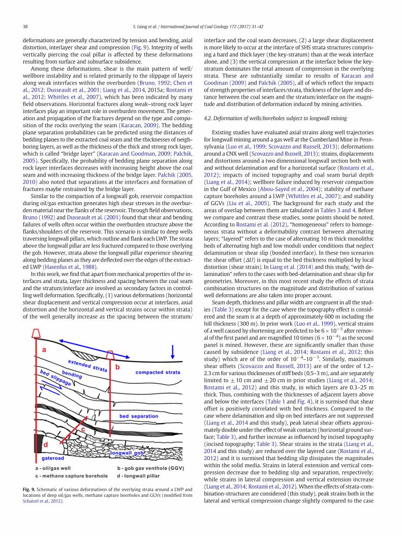
38 S. Liang et al. / International Journal of Coal Geology 172 (2017) 31–42
deformations are generally characterized by tension and bending, axialdistortion, interlayer shear and compression (Fig. 9). Integrity of wellsvertically piercing the coal pillar is affected by these deformationsresulting from surface and subsurface subsidence.
Among these deformations, shear is the main pattern of well/wellbore instability and is related primarily to the slippage of layersalong weak interfaces within the overburden (Bruno, 1992; Chen etal., 2012; Dusseault et al., 2001; Liang et al., 2014, 2015a; Rostami etal., 2012; Whittles et al., 2007), which has been indicated by manyfield observations. Horizontal fractures along weak–strong rock layerinterfaces play an important role in overburden movement. The gener-ation and propagation of the fractures depend on the type and compo-sition of the rocks overlying the seam (Karacan, 2009). The beddingplane separation probabilities can be predicted using the distances ofbedding planes to the extracted coal seam and the thicknesses of neigh-boring layers, as well as the thickness of the thick and strong rock layer,which is called “bridge layer” (Karacan and Goodman, 2009; Palchik,2005). Specifically, the probability of bedding plane separation alongrock layer interfaces decreases with increasing height above the coalseam and with increasing thickness of the bridge layer. Palchik (2005,2010) also noted that separations at the interfaces and formation offractures maybe restrained by the bridge layer.
Similar to the compaction of a longwall gob, reservoir compactionduring oil/gas extraction generates high shear stresses in the overbur-denmaterial near theflanks of the reservoir. Throughfield observations,Bruno (1992) and Dusseault et al. (2001) found that shear and bendingfailures of wells often occur within the overburden structure above theflanks/shoulders of the reservoir. This scenario is similar to deep wellstraversing longwall pillars, which outline andflank each LWP. The strataabove the longwall pillar are less fractured compared to those overlyingthe gob. However, strata above the longwall pillar experience shearingalong bedding planes as they are deflected over the edges of the extract-ed LWP (Hasenfus et al., 1988).
In thiswork,we find that apart frommechanical properties of the in-terfaces and strata, layer thickness and spacing between the coal seamand the stratum/interface are involved as secondary factors in control-lingwell deformation. Specifically, (1) various deformations (horizontalshear displacement and vertical compression occur at interfaces, axialdistortion and the horizontal and vertical strains occur within strata)of the well generally increase as the spacing between the stratum/
Fig. 9. Schematic of various deformations of the overlying strata around a LWP andlocations of deep oil/gas wells, methane capture boreholes and GGVs (modified fromSchatzel et al., 2012).
interface and the coal seam decreases, (2) a large shear displacementis more likely to occur at the interface of SHS strata structures compris-ing a hard and thick layer (the key-stratum) than at the weak interfacealone, and (3) the vertical compression at the interface below the key-stratum dominates the total amount of compression in the overlyingstrata. These are substantially similar to results of Karacan andGoodman (2009) and Palchik (2005), all of which reflect the impactsof strength properties of interfaces/strata, thickness of the layer and dis-tance between the coal seam and the stratum/interface on the magni-tude and distribution of deformation induced by mining activities.
4.2. Deformation of wells/boreholes subject to longwall mining
Existing studies have evaluated axial strains along well trajectoriesfor longwall mining around a gaswell at the CumberlandMine in Penn-sylvania (Luo et al., 1999; Scovazzo and Russell, 2013); deformationsaround a CNXwell (Scovazzo and Russell, 2013); strains, displacementsand distortions around a two dimensional longwall section both withand without delamination and for a horizontal surface (Rostami et al.,2012); impacts of incised topography and coal seam burial depth(Liang et al., 2014); wellbore failure induced by reservoir compactionin the Gulf of Mexico (Abou-Sayed et al., 2004); stability of methanecapture boreholes around a LWP (Whittles et al., 2007); and stabilityof GGVs (Liu et al., 2005). The background for each study and theareas of overlap between them are tabulated in Tables 3 and 4. Beforewe compare and contrast these studies, some points should be noted.According to Rostami et al. (2012), “homogeneous” refers to homoge-neous strata without a deformability contrast between alternatinglayers; “layered” refers to the case of alternating 10 m thick monolithicbeds of alternating high and low moduli under conditions that neglectdelamination or shear slip (bonded interface). In these two scenariosthe shear offset (ΔU) is equal to the bed thickness multiplied by localdistortion (shear strain). In Liang et al. (2014) and this study, “with de-lamination” refers to the cases with bed-delamination and shear slip forgeometries. Moreover, in this most recent study the effects of stratacombination structures on the magnitude and distribution of variouswell deformations are also taken into proper account.
Seamdepth, thickness and pillar width are congruent in all the stud-ies (Table 3) except for the case where the topography effect is consid-ered and the seam is at a depth of approximately 600 m including thehill thickness (300 m). In prior work (Luo et al., 1999), vertical strainsof awell caused by shortening are predicted to be 6 × 10⁻⁵ after remov-al of the first panel and aremagnified 10 times (6× 10−4) as the secondpanel is mined. However, these are significantly smaller than thosecaused by subsidence (Liang et al., 2014; Rostami et al., 2012; thisstudy) which are of the order of 10−4–10−3. Similarly, maximumshear offsets (Scovazzo and Russell, 2013) are of the order of 1.2–2.3 cm for various thicknesses of stiff beds (0.5–3m), and are separatelylimited to ±10 cm and ±20 cm in prior studies (Liang et al., 2014;Rostami et al., 2012) and this study, in which layers are 0.3–25 mthick. Thus, combining with the thicknesses of adjacent layers aboveand below the interfaces (Table 1 and Fig. 4), it is surmised that shearoffset is positively correlated with bed thickness. Compared to thecase where delamination and slip on bed interfaces are not suppressed(Liang et al., 2014 and this study), peak lateral shear offsets approxi-mately double under the effect ofweak contacts (horizontal ground sur-face; Table 3), and further increase as influenced by incised topography(incised topography; Table 3). Shear strains in the strata (Liang et al.,2014 and this study) are reduced over the layered case (Rostami et al.,2012) and it is surmised that bedding slip dissipates the magnitudeswithin the solid media. Strains in lateral extension and vertical com-pression decrease due to bedding slip and separation, respectively;while strains in lateral compression and vertical extension increase(Liang et al., 2014; Rostami et al., 2012).When the effects of strata-com-bination-structures are considered (this study), peak strains both in thelateral and vertical compression change slightly compared to the case

Table 3Comparison of various deformational modes of wells subject to longwall mining with previous studies.
Study performed by Burialdepth/m
Seamthickness/m
Pillarwidth/m
First mined panel Second mined panel
ShearoffsetΔU/cm
Shearstrain/ɛxy
Lateralstrain/ɛxx
Verticalstrain/ɛyy
ShearoffsetΔU/cm
Shearstrain/ɛxy
Lateralstrain/ɛxx
Verticalstrain/ɛyy
Luo et al., 1999 307 1.9 56 – – – −6 E-5 – – – −6 E-4Su, 2009 (Scovazzo and Russell, 2013) 315 1.7 65 – – – – 1.2– 2.3 – – –Rostami et al.,2012
Homogeneous 300 2.0 50 0–1.2 0–1 E-3 −1–4E-4
−2–0 E-4 0–3 0–3 E-3 0–2 E-3 −2–0E-3
Layered 300 2.0 50 −2–7 −2–7E-3
−1–8E-3
−5–2 E-3 −8–6 −8–6E-3
−1–8E-3
−8–10E-3
Liang et al.,2014 (withdelamination)
Horizontal 300 2.0 50 3–17 −1–22E-4
−26–52E-4
−15–149E-4 −17–13 −22–23E-4
−47–77E-4
−22–164E-4
Incised 300 +300
2.0 50 2–22 −3–15E-4
−3–5E-3
−2–0 E-3 −20–15 −23–13E-4
−6–10E-3
−3–1E-3
This study (withdelamination)
with effects of stratacombination structures beenunder consideration
305.3 2.0 50 3–14 −1–13E-4
−25–80E-4
−15–6 E-4 −13–10 −24–14E-4
−43–116E-4
−24–7E-4
39S. Liang et al. / International Journal of Coal Geology 172 (2017) 31–42
where the formation is uniformly alternating and comprising ~10 mthick alternating shale and sandstone layers (Liang et al., 2014). Thesepeak strains all occur within the seam or in the lower part of the imme-diate roof. While the largest lateral extensional strains increase and thepeak vertical extensional strains decrease drastically due to the pres-ence of the key-stratum.
We also make a comparison of casing/borehole strains between thisnew work and previous studies regarding the stability of methane cap-ture boreholes and GGVs in gassy coal seams, and casing/wellbore fail-ure induced by reservoir compaction in the petroleum industry.Statistical data from these previous studies are tabulated in Table 4, inwhich “FTD” and “MPR” separately refer to field test data and numericalmodel predicted results that have been confirmed by field observationafter 6 years production; “FEMW” and “FEMWO” separately indicatethe hybrid finite element predicted results both with and without theconsideration of casing, cement and rock rigidity; and “GM” and “GDF”separately represent results predicted from a geomechanical modeland calculated from the Gaussian distribution function.
Vertical strains induced by reservoir compaction and resulting frompore collapse of weak reservoir rocks after 5–6 years production arelarger than those of wells in this work by over one order of magnitude.Specifically, the vertical compressional and tensional strains of casingsare approximately 16–29 and 10–16 times, respectively, as large asthose of wells subject to longwall coal mining (i.e. this study, after thetwin flanking panels are both mined) (Table 4). It is surmised that theaccumulated larger non-uniform subsurface subsidence due to thedeep reservoir (N5000 m) and long term (N5 years) production ac-counts for this difference in magnitude of vertical strains. However,the horizontal compressional casing strains are much less than thoseof wells in this study, accounting for 5%–47% of the later; and the
Table 4Statistical variations of strains of wellbores, methane capture boreholes and GGVs from previo
Study conducted by Reserv
Abou-Sayed, et al., 2004 Wellbore failure induced by reservoir compaction Case 1 5182Case 2 6096Case 3 6096
Liu, et al., 2005 GGVs 475
Whittles, et al., 2007 Methane capture boreholes 770This study Oil/gas wells (after the twin LWPs are both removed) 305.3
horizontal tensional casing strains are also less compared to those ofwells in this work, accounting for 49%–95% of the later.
The greatest vertical compressional strain of GGVs calculated fromthe Gaussian distribution function is of the order of −74 E-4 (Liu etal., 2005), which is between five and three times that of wells in thiswork after the twin panels flanking the coal pillar are sequentially re-moved. This might imply more intense movement and deformation ofstrata above the longwall gob compared with that within the strataabove the coal pillar (Fig. 9). Certainly, the seam depth, mining heightand mechanical properties of the overlying strata and interfaces couldalso dictate the magnitude of the deformation of the wells/boreholes.To be noted is that the axial distribution of vertical compressional strainof the GGVs, calculated from the Gaussian distribution function, isroughly similar to that of wells in this work (Fig. 8). However, theGaussian model cannot accommodate the impacts of lithology andbed thickness.
Similarly, shear strains of methane capture boreholes drilled from thetailgate roadway and across the shallow roof (Fig. 9) in a UK active LWPlocated in the Parkgate coal seam at a depth of 770 m (Whittles et al.,2007) aremuch greater than those ofwells drilled through a longwall pil-lar. This is due principally to the comprehensive effects of severe sheardeformation within the shallow overburden at the inboard edges of thepanel (Fig. 9) and the deeper seam depth. Magnitudes of shear strainsof themethane capture boreholes (of the order of 10−2–10−1) are nearly50–92 times those of wells in this work (of the order of 10−3).
4.3. Drilling path optimization for wells penetrating the longwall pillar
We conduct a thorough integrated evaluation of various deforma-tions of the five well trajectories analyzed in the previous section,
us studies.
oir/seam depth/m Seam thickness/m Strains
– Vertical strain (FTD) −38–11 E-3– Vertical strain (MPR) −67–8 E-3– Vertical strain FEMWO −52–1 E-3
FEMW −41–1 E-3GM −70–7 E-3
Horizontal strain FEMWO −2–76 E-4FEMW −2–57 E-4GM −2–11 E-3
2.5 Vertical compressionalstrain (GDF)
−74 E-4
2.0 Shear strain (GM) −12–2 E-22.0 Vertical strain −24–7 E-4
Horizontal strain −43–116 E-4Shear strain −24–14 E-4

40 S. Liang et al. / International Journal of Coal Geology 172 (2017) 31–42
especially the horizontal shear offset which jeopardizes well integritythe most. Trajectory W3 is the recommended drilling path for thewell. That is, positioning the well closer to the rib of the second minedpanel favors well integrity. It is speculated that, based on our numericalmodeling results, part of the deformation of the wellbore in the overly-ing strata can be recovered and that some deformations cannot be re-stored (and may even intensify) after the twin panels flanking thecoal pillar are sequentially removed. Although the authors did not dis-cuss the relation between the position of the well within the coal pillarand its stability, supporting evidence for this viewpoint is available fromfield engineering practice (Peng et al., 2003). Fig. 10 shows the layoutsof the gateroad system of both the stable well case and that of the failedwell. For the successful case (Fig. 10 (a)), the gaswell is located closer tothe rib of the second advancing panel (13.2m out from the pillar-centerfor a 56.9 m wide three-entry longwall pillar) (Table 5) and no casingdestruction was observed after the twin flanking panels were sequen-tially removed. While for the case of failure (Fig. 10 (b)), the gas wellis located closer to the rib of the first mined panel (12.3 m out fromthe pillar-center for a 56.0 m wide three-entry longwall pillar) (Table5) and plastic failure was observed on the inner tubing of the wellafter panel 2 was mined.
5. Conclusions
Increased demand for energy encourages the exploitation of uncon-ventional hydrocarbon resources. In areas where the overlaying coaland deep hydrocarbon resources coexist, longwall mining may inevita-bly damage the transiting wells; therefore, maintaining the stability ofthese wells has become a significant issue impeding the co-extractionof these resources. This paper investigates the effect of strata combina-tion structures on themagnitude and distribution of various well defor-mations, and explores the optimal well drilling path favoring the wellintegrity. The main conclusions are as follows:
Fig. 10. The spatial relationship between the gas well and the twin LWPs flanking the longw
(1) The effects of various combinations of strata onwell deformation(including horizontal shear offset and vertical compression oc-curring at the weak interfaces between alternating layers, andthe axial distortion, horizontal and vertical tension and compres-sion occurringwithin the strata) lie essentially in themechanicalproperties of the interfaces and strata. The stratum thickness andthe spacing between the coal seam and the stratum/interface arealso involved as secondary factors in controlling well deforma-tion. Longwall mining-induced interfacial shear displacementsat interfaces between a monolithic rigid bed (e.g. the key-stra-tum) and its immediate overlaying and underlaying soft beds(e.g. shales/mudstones, SHS strata structure), especially at the in-terface sandwiched above by a thick stiff layer and below by athick soft layer, are much larger than those at interfaces withsimply low stiffness. However, wells are not susceptible to largehorizontal shear slippage at interfaces between one thin soft in-terlayer and the stiff beds directly above and below (HSH stratastructure), and between the topsoil and its underlaying bedrock.Well deformations arising both at interfaces andwithin layers allsignificantly intensify in the vicinity of the mined seam. Wells insuch areas are therefore at high risk of instability.
(2) Different types of strata combinations (the topsoil-bedrock, HSH,and SHS strata structures) influence themagnitude and distribu-tion of various well deformations to varying extents. The hori-zontal and vertical strains in the topsoil change gradually thenvary abruptly at the interface between the topsoil and its under-laying bedrock. Wells in the upper part of the topsoil are subjectto horizontal tension after either one or both panels are removed,while the lower part is compressed. Lateral strains are dominatedby tension in the upper part of stiff beds (e.g. the upper part ofthe bedrock, the key stratum, and the sandstone directly belowthe thin weak interlayer) which directly lie beneath the softbeds. The larger lateral tensile strains are for wells in the shallowroof (~5–20 m above the seam). While the larger lateral
all coal pillar: (a) successful case and (b) failure case. (modified from Peng et al., 2003).

Table 5Comparison of longwall pillar configuration and well trajectory locations between this work and two field cases.
Study conducted by Pillar configuration (yield pillar+ gateroad + barrier pillar)
Panelwidth/m
Seam burialdepth/m
Miningheight/m
Entrieswidth/m
Width of the barrier pillar the gaswell piercing/m
Off centerdistance/m
Peng, et al.,2003
Successfulcase
3-entrysystem
21.5 + 4.9 + 30.5= 56.9 m
305 159 2.4 4.9 30.5 13.2
Failed case 19.3 + 5.0 + 31.7= 56 m
274 287 1.9 5.0 31.7 −12.3
This study 3-entrysystem
15 + 5.0 + 30 = 50m
370 305.3 2.0 5.0 30.0 7.5
Note: For “off center distance”, negative and positive values represent that the well is drilled off the pillar centerline and close to the first and second mined panel, separately.
41S. Liang et al. / International Journal of Coal Geology 172 (2017) 31–42
compressive strains are for wells in the vicinity of the seam(within ~5 m above and below the seam) and peak in the coalseam.
(3) Longitudinal well deformation in soft strata is dominated bycompression especially in the upper part of the layer. Verticaltension plays a dominant role in well deformation in stiff/hardlayers, especially in their lower reaches. The shallow topsoil hasa greater vertical well deformation that is dominated by tension.The vertical interfacial compression is larger at interfaces belowthe key-stratum, peaking at the interface between the coalseamand its immediate roof. The key-stratumbehaves like a bar-rier layer, preventing the overlying strata from bending and sub-siding and preventing mining-induced damage frompropagating upwards. Small increases in vertical interfacial com-pression are detected at interfaces between 1) the key-stratumand its immediately underlying soft layer, 2) a thinweak stratumand its immediately overlying hard layer, and 3) topsoil and thebedrock after either one or both panels are removed. Since thestrata beneath the topsoil alternate as soft mudstones and stiffsandstones, the axial distortion of wells traversing these stratafluctuate. Well distortion within the soft strata exceeds that inthe stiff strata, generally reaching 3 to 5 times the distortion ofthe latter, and reaching a peak distortion of ~10−3 for the wellin the shallow roof (~8 m above the seam).
(4) After extraction of the twin LWPs, the interfacial horizontal shearoffsets and the intra-formational axial distortion of the well re-bounds to some extent in the upper part of the overlying strata,due to the symmetry of mining geometry. However, in theseam and its shallow roof (within 30 m), these deformations in-tensify because of the intense influence of the mining of the sec-ond LWP. The intra-formational vertical and horizontal strains ofthewell (for most of the length of thewell) increase further afterthe extraction of the second LWP. And this increment increasessharply as the spacing between the stratum and the coal seamdecreases.
(5) In the cross section of the pillar, various deformations of wellsW1 and W5, which traverse the edges of the longwall pillar, aregreater to varying extents than those of wells W2-W4 after thetwin LWPs are sequentially excavated. The maximum lateralshear offset of well W3 is 97.5 mm, which is the least amongthe five candidate paths of wells in the entire mining cycle ofthe twin panels. Well W2, which is closest to the pillar centerand traverses the edge of the barrier pillar, has the lowest inter-facial compression (−488 mm), but this is close to that of wellW3 (−498 mm). In addition, there is a prominent increase inthe axial distortion and lateral tensile strain for well W2 in theupper part of the key-stratum after either one or both panelsare removed. Thus, through an integrated consideration of vari-ous deformations of these five wells, especially the lateral sheardeformation which threatens well integrity the most, trajectoryW3 (deviating suitably from the pillar centerline and close tothe second mined panel) is the recommended drilling path forthe well. Supporting evidence for this viewpoint is apparent
from field engineering practice.(6) Spatially, magnitudes of various deformations of strata directly
over the gob, pillars and edges of the panel differ. Due to the larg-er subsidence of overlying strata above the gob compared withthat occurring within the overlying strata above the pillar, verti-cal compressive strains of the GGVs are usually greater thanthose of wells in the overlying strata of the pillar. As for methanecapture boreholes sidetrack drilled from the tailgate and acrossthe shallow roof of an LWP, the shear strains of boreholes occuras the strata in the overlying edges of the panel bend, tilt andsubside during the panel-advance cycle and these are far largerthan those for wells piercing the pillar. While for the hydrocar-bon wells, the vertical casing strains (both compressive and ex-tensile) induced by reservoir compaction as a result of porecollapse of weak reservoir rocks after long-term production aregenerally larger than those of wells penetrating the longwall pil-lars by more than one order of magnitude.
Acknowledgements
Financial support for this work, provided by China Postdoctoral Sci-ence Foundation (2015M581893), theNational Natural Science Founda-tion of China (Nos. 41602174 and 51674248), the FundamentalResearch Funds for the Central Universities (2015XKZD04), and the Pri-ority Academic Program Development of Jiangsu Higher Education In-stitutions (PAPD), is gratefully acknowledged.
References
Abou-Sayed, A.S., Meng, F.H., Wang, G., 2004. Compaction-Induced Wellbore Failure andFault Instability: A Hybrid Approach. American Rock Mechanics Association.
Bruno, M.S., 1992. Subsidence-induced well failure. SPE Drill. Eng. 7 (2), 148–152 (SPE-20058-PA).
Chen, J., Wang, T., Zhou, Y., Zhu, Y., Wang, X., 2012. Failure modes of the surface ventholecasing during longwall coal extraction: a case study. Int. J. Coal Geol. 90–91, 135–148.
Dodson, J.K., 2004. Gulf of Mexico ‘trouble time’ creates major drilling expenses. Offshore64 (1).
Dusseault, M.B., Bruno, M.S., Barrera, J., 2001. Casing shear: causes, cases, cures. SPE72060. SPE Drill. Complet. 16 (2), 98–107.
Fan, G.W., Zhang, D.S., 2015. Mechanisms of aquifer protection in underground coal min-ing. MineWater Environ 34, 95–104.
Ghazvinian, A.H., Taghichian, A., Hashemi, M., Mar'Ashi, S.A., 2010. The shear behavior ofbedding planes of weakness between two different rock types with high strength dif-ference. Rock Mech. Rock. Eng. 43, 69–87.
Hasenfus, G.J., Johnson, K.L., Su, D.W.H., 1988. A hydrogeomechanical study of overburdenaquifer response to longwall mining. Proceeding of 7th International Conference onGround Control in Mining. West Virginia University, Morgantown, pp. 149–162.
Huang, H., 2010. Study on geological theories of stress relief coalbed methane drainagefrom the distant protected seam by vertical surface wells and their application inHuainan coal mine area. Ph.D. Thesis. China University ofMining and Technology, Xu-zhou, China.
Itasca Ltd., 2002. FLAC2D, User's Manual. Itasca Consulting Group, Inc.Karacan, C.Ö., 2009. Reservoir rock properties of coal measure strata of the LowerMonon-
gahela Group, Greene County (Southwestern Pennsylvania), from methane controland production perspectives. Int. J. Coal Geol. 78, 47–64.
Karacan, C.Ö., 2015. Analysis of gob gas venthole production performances for strata gascontrol in longwall mining. Int. J. Rock Mech. Min. Sci. 79, 9–18.

42 S. Liang et al. / International Journal of Coal Geology 172 (2017) 31–42
Karacan, C.Ö., Goodman, G., 2009. Hydraulic conductivity changes and influencing factorsin longwall overburden determined by slug tests in gob gas ventholes. Int. J. RockMech. Min. Sci. 46, 1162–1174.
Karacan, C.Ö., Diamond, W.P., Esterhuizen, G.S., Schatzel, S.J., 2005. Numerical analysis ofthe impact of longwall panel width on methane emissions and performance of gobgas vent holes. Proc. Int. Coalbed Methane Symposium (Paper 0505, Tuscaloosa, AL.18–19 May. 28 pages).
Karacan, C.Ö., Esterhuizen, G.S., Schatzel, S., Diamond, W.P., 2007. Reservoir simulation-based modeling for characterizing longwall methane emissions and gob gas ventholeproduction. Int. J. Coal Geol. 71, 225–245.
Karacan, C.Ö., Ruiz, F.A., Cotè, M., Phipps, S., 2011. Coal mine methane: a review of captureand utilization practices with benefits to mining safety and to greenhouse gas reduc-tion. Int. J. Coal Geol. 86, 121–156.
Liang, S., 2015. Study on the stability of vertical shale gas wells penetrating longwall min-ing areas. Ph.D. Thesis. China University of Mining and Technology, Xuzhou, China.
Liang, S., Elsworth, D., Li, X., Yang, D., 2014. Topographic influence on stability for gaswells penetrating longwall mining areas. Int. J. Coal Geol. 132, 23–36.
Liang, S., Elsworth, D., Li, X., Fu, X., Yang, D., Yao, Q., Wang, Y., 2015a. Dynamic impacts onthe survivability of shale gas wells piercing longwall panels. Journal of Natural GasScience and Engineering 26, 1130–1147.
Liang, S., Li, X., Yao, Q., Yang, D., 2015b. Influence of weak interlayer contacts on the sta-bility of shale gas wells transiting minable coal seams. Journal of Mining and SafetyEngineering 32, 471–477 (In Chinese with English abstract).
Liu, Y.Z., Lu, T.K., Yu, H.Y., 2005. Surface boreholes for drainage of goaf gas and its stabilityanalysis. Chin. J. Rock Mech. Eng. 24, 4982–4987 (In Chinese with English abstract).
Lu, C.P., Liu, Y., Wang, H.Y., Liu, P.F., 2016. Microseismic signals of double-layer hard andthick igneous strata separation and fracturing. Int. J. Coal Geol. 160, 28–41.
Luo, Y., Peng, S., Zhang, Y., 1999. Analysis of the Observed Failure on the Inner Tubing ofGas Well W-510 Below the Coal Seam. College of Engineering andMineral Resources,West Virginia University (May 24).
Luo, Y., Peng, S., Zhang, Y., Mordy, K., 2002. Techniques for assessing the effects oflongwall mining on gas and oil wells. 2002 SME Annual Meeting and Exhibit,pp. 25–27 February.
Majdi, A., Hassani, F.P., Nasiri, M.Y., 2012. Prediction of the height of destressed zoneabove the mined panel roof in longwall coal mining. Int. J. Coal Geol. 98 (1), 62–72.
Miyazaki, B., 2009. Well Integrity: An Overlooked Source of Risk and Liability for Under-ground Natural Gas Storage. Lessons Learned from Incidents in the USA. vol. 313.Geological Society London Special Publications, pp. 163–172.
Palchik, V., 2003. Formation of fractured zones in overburden due to longwall mining. En-viron. Geol. 44, 28–38.
Palchik, V., 2005. Localization of mining-induced horizontal fractures along rock layer in-terfaces in overburden: field measurements and prediction. Environ. Geol. 48, 68–80.
Palchik, V., 2010. Experimental investigation of apertures of mining-induced horizontalfractures. Int. J. Rock Mech. Min. Sci. 47 (3), 502–508.
Peng, S., Morsey, K., Zhang, Y., Luo, Y., Heasley, K., 2003. Technique for assessing the ef-fects of longwall mining on gas wells-two case studies. Transactions-society for min-ing metallurgy and exploration incorporated 314, 107–115.
Preusse, A., 2001. Effect of face advance rates on the characteristics of subsidence process-es associated with US and Germany longwall mining. 20th International Conferenceon Ground Control in Mining, Morgantown, WV, pp. 140–148.
Qian, M., 1996. Theoretical study of key stratum in ground control. J. China Coal Soc. 21,225–230.
Rice, G.S., Hood, O.P., 1913. Oil and Gas Wells Through Workable Coal Beds (No. BM-BULL-65). Bureau of Mines, Washington, DC (USA).
Richard, R., Randolph, J., Zipper, D., 1990. High extraction mining, subsidence, andVirginia's water resources. chapter 4. Subsidence Effects onWater Resources. Virginia
Center for Coal & Energy Research. Virginia Polytechnic Institute and state University,Virginia, pp. 17–20.
Rostami, J., Elsworth, D., Watson, R., 2012. Study of Borehole Stability for Gas Wells inLongwall Mining Areas (Report Submitted to Range Resources).
Rueda, J., Noreña, N., Oliveira, M., Roehl, D., 2014. Numerical models for detection of faultreactivation in oil and gas fields. 48th US Rock Mechanics Conference (ARMA 2014),pp. 1–8.
Schatzel, S.J., Karacan, C.Ö., Dougherty, H., Goodman, G.V.R., 2012. An analysis of reservoirconditions and responses in longwall panel overburden during mining and its effecton gob gas well performance. Eng. Geol. 127, 65–74.
Scovazzo, V.A., Russell, P.M., 2013. Industry research into gas and oil well protective coalpillar design. 32nd International Conference on Ground Control in Mining, Morgan-town, WV, pp. 45–52.
Su, W.H., 2016. Effects of longwall-induced stress and deformation on the stability andmechanical integrity of shale gas wells drilled through a longwall abutment pillar.35th International Conference on Ground Control in Mining, Morgantown, West Vir-ginia, pp. 1–7.
Sun, H., 2008. Study on the deformation fracture mechanism of the surface borehole withthe excavation disturbance. Ph.D. Thesis. Chongqing University, Chongqing, China.
Vidic, R.D., Brantley, S.L., Vandenbossche, J.M., Yoxtheimer, D., Abad, J.D., 2013. Impact ofshale gas development on regional water quality. Science 340 (6134), 1235009.
Wang, J., Wei, X., Chen, S., 2012. Fracture and seepage characteristics in the floor stratawhen mining above a confined aquifer. J. China Univ. Min. Technol. 41, 536–542 (InChinese with English abstract).
Wang, J., Li, H., Chen, P., 2014. Exploration and practice on treatment technology of de-pleted oil wells in coal mine. Coal Technology 33, 262–265 (In Chinese with Englishabstract).
Wang, Y., Watson, R., Rostami, J., Wang, J., Limbruner, M., He, Z., 2013. Study of boreholestability of Marcellus shale wells in longwall mining areas. J. Pet. Explor. Prod.Technol. 1–13.
Whittles, D.N., Lowndes, I.S., Kingman, S.W., Yates, C., Jobling, S., 2006. Influence of geo-technical factors on gas flow experienced in a UK longwall coal mine panel. Int.J. Rock Mech. Min. Sci. 43, 369–387.
Whittles, D.N., Lowndes, I.S., Kingman, S.W., Yates, C., Jobling, S., 2007. The stability ofmethane capture boreholes around a long wall coal panel. Int. J. Coal Geol. 71,313–328.
Xu, H., Sang, S., Han, J., Huang, H., Cheng, Z., Ren, B., 2011. Relationship between rockmassstructure and stability of surface well for released coal gas. Journal of Mining andSafety Engineering 28, 90–95 (In Chinese with English abstract).
Yan, C., Deng, J., Yu, B., 2013. Wellbore stability in oil and gas drilling with chemical-me-chanical coupling. Sci. World J. 2013.
Yun, S., 2014. Analysis on the impacts of simultaneous extraction of coal and natural gason coal mine safety. Science and Technology Information, Heilongjiang 57 (InChinese).
Zeynali, M.E., 2012. Mechanical and physico-chemical aspects of wellbore stability duringdrilling operations. J. Pet. Sci. Eng. 82-83, 120–124.
Zhai, C., Xu, Y., Xiang, X., Yu, X., Zou, Q., Zhong, C., 2015. A novel active prevention tech-nology for borehole instability under the influence of mining activities. Journal ofNatural Gas Science and Engineering 27, 1585–1596.
Zhang, J., Lang, J., Standifird, W., 2009. Stress, porosity, and failure-dependent compres-sional and shear velocity ratio and its application to wellbore stability. J. Pet. Sci.Eng. 69 (3), 193–202.
Zabetakis, M.G., Moore Jr., T.D., Nagel, A.E., Carpetta, J.E., 1972. Methane Emission in CoalMines: Effects of Oil and Gas Wells. 7658. US Bureau of Mines Report ofInvestigations.