international journal of heat and mass...
TRANSCRIPT
International Journal of Heat and Mass Transfer 117 (2018) 1158–1168
Contents lists available at ScienceDirect
International Journal of Heat and Mass Transfer
journal homepage: www.elsevier .com/locate / i jhmt
Flow-boiling canopy wick for extreme heat transfer
https://doi.org/10.1016/j.ijheatmasstransfer.2017.10.0790017-9310/� 2017 Elsevier Ltd. All rights reserved.
⇑ Corresponding author.E-mail address: [email protected] (M. Kaviany).
Minki Kim, Massoud Kaviany ⇑Department of Mechanical Engineering, University of Michigan, Ann Arbor, MI 48109, USA
a r t i c l e i n f o a b s t r a c t
Article history:Received 7 August 2017Received in revised form 17 October 2017Accepted 19 October 2017Available online 5 November 2017
Keywords:Boiling metamediumBoiling heat flux and conductance limitsVapor ventingTwo-phase flow stability
The maximum theoretical boiling heat transfer rate qmax is set by interface unidirectional thermal vaporflux, and quest continues for achieving a high fraction of it under saturated liquid flow. We introduce theflow-boiling canopy wick (FBCW) employing film (meniscus) evaporation and perforated screenlayerseparating the liquid stream from the underlying vapor space. The vapor vents continuously throughperiodic perforations, in contrast to plain surface which becomes completely covered by vapor at highheat flux. The FBCW allows streamwise liquid tracks on the screenlayer between perforations providingcapillary liquid flow toward heated surface and evaporation on high-effective-conductivity monolayerwick. Under extreme heat flux, various hydrodynamic limits prevent liquid supply and vapor removal,i.e., the capillary-viscous, wick superheat, perforation pressure drop and chocking and liquid-vaporstability limits. The liquid and vapor inertiae control the streamwise continuous liquid track (withisolated and/or merged vapor track) and for saturated water at 1 atm CFD and wick pressure drop predictheat flux up to 0.1qmax = 20 MW/m2, an order-of-magnitude larger than the nucleate flow-boiling limit.The concept of replacing the chaotic nucleated bubbles with the structured, continuous vapor ventingin the periodic FBCW transforms boiling heat transfer and its upper limit.
� 2017 Elsevier Ltd. All rights reserved.
1. Introduction and flow-boiling canopy wick
Boiling heat flux limit is governed by the supply of heat andliquid for evaporation, and removal of vapor (allowing for liquidirrigation), with the upper limit set by the maximum vapor flowrate predicted by the kinetic theory of gases. The surface-convection thermal-hydraulic limitations by boundary layers andliquid-vapor phase competition can be controlled using 3-Dmultiscale, unit-cell based boiling metamedium. The metamediumcombines (a) high-effective-thermal-conductivity capillary mono-layer for evaporation, (b) high-permeability liquid supply postsseparating the liquid and vapor phases, and flows, and (c) uniquelydesigned liquid- and vapor-tracks – leading to record high heatflux and thermal conductance. Metamaterials are engineered(synthesized from multiple elements in repeating patterns) to pro-vide properties not naturally available employing heterogeneitiesfor effective macroscopic transport (e.g., multiscale function-designed porous media).
While low thermal resistance has been observed for subcooledboiling, the saturated flow boiling, even at very large liquid speed(up to 10 m/s), has not yet been able to reach the low thermalresistance achieved with multidimensional wicks under saturation.
Based a review of boiling in coated surface [1], here we introduce amultiscale 3-D flow-boiling canopy wick (FBCW) for achieving lowthermal resistance and high critical heat flux (CHF) in boundary-layer flow boiling. The selection of flow conditions is to initiallyavoid the effect of the channel hydraulic diameter, although itshould be mentioned that this wick has dimension of the orderof millimeter, so it is suitable for multi-millimeter and larger chan-nels (for thermal management and vapor production). The struc-ture allows for film evaporation over a thin porous-layer coatingcalled the monolayer, as shown in Fig. 1. The structure is periodicin two directions, and its simplest unit cell will contain four posts,a screenlayer (two or three layers) acting as roof with a centeredperforation, and a thin porous layer making the floor of the canopywick. While thin, this layer has an optimal combination ofpermeability and maximum capillary pressure to spread the liquidsupplied through the high permeability posts. The aim is to createand maintain a vapor space for steady and uniform film evapora-tion, while allowing for liquid supply and vapor escape.
2. Flow-boiling heat flux and conductance limits
The available results on maximum heat flux (q), and heat trans-fer coefficient or specific conductance (G=A) for plain and coatedsurfaces, under pool boiling (PB) [2–7], flow boiling (FB, no sub-cooling) [8–10], and with multi-artery heat-pipe spreader
Nomenclature
A area (m2)C; c coefficientscd discharge coefficientcp heat capacity (J/kg-K)D;d diameter (m)Fr Froude numberf friction coefficient, forceG=A heat transfer coefficient (W/m2-K)g gravitational acceleration (m/s2)H height (m)Dhlg heat of evaporation (kJ/kg)K permeability (m2)k thermal conductivity (W/m-K)kB Boltzmann constant (J/K)L length, pitch, thickness (m)M mass (kg)Ma Mach numberm molecular mass (g/mol)Nper ratio of monolayer unit cell per perforationNp packing numbernsh number density of shute wire (1/in2)nwa number density of warp wire (1/in2)p pressure (Pa)Q heat flow rate (W)q heat flux (W/m2)R thermal resistance (K/W)Re Reynolds numberr radial location, radius (m)s substrate, saturationT temperature (K)u velocity (m/s)v velocity (m/s)W;w width (m)We Weber numberx quality, position in streamwise direction (m)hi average
Greek symbolsa gas void fractionb ratio of perforation area to area before perforationD difference, dropdl liquid thickness (m)� porosity
c heat capacity ratiojg gas interface curvature (1/m)k wavelength (m)km pitch of permeable periodic stacks (m)l viscosity (Pa-s)q density (kg/m3)r surface tension (N/m)hc contact angle (�)
Subscriptsac cross-sectionalCHF critical heat fluxc capillary, channel, cooling, crosscr criticalc-v capillary-viscouse effective, evaporatorFB flow boilingg gash heatedI isolatedi index of node, inletl liquidlg liquid-gas phase changel� g; st liquid-gas stabilityM mergedm monolayer wicksmax maximumN total number of nodeso openingPB pool boilingp post (artery)per perforationpo pores screen mesh, surface, surface tensionsh shute wiret thermalu fluid flowwa warp wireZ Zuberl across$ along
M. Kim, M. Kaviany / International Journal of Heat and Mass Transfer 117 (2018) 1158–1168 1159
(MAHPS) [1] are shown in Fig. 2, for water at 1 atm. The surface-convection conductance for impinging jet is based on the resultsof [11] and review in [12]. Since the surface-convection resistanceis in series with the substrate conduction resistance, the conduc-tion conductance is also shown (under copper or synthetic dia-mond as material). The predicted superior performance [q up to20 MW/m2 and (G=A) over 0.2 MW/m2-K] of the proposed FBCWis also shown. In general, coatings and nano/microstructuresreduce the surface superheat Ts � Tlg (Tlg is saturation tempera-ture) by either increasing the nucleation sites or creating filmevaporation over thin, high effective conductivity wicks. They alsotend to enhance the CHF governed by the liquid-vapor hydrody-namic instability or the capillary-viscous limit of liquid flowthrough porous bodies. The vapor escaping paths are more readilyaccommodated, but vapor chocking limit can occur.
The maximum theoretical heat flux is based on the interfacial,unidirectional thermal flux of vapor qmax [13–15]
qmax ¼ qgDhlgðkBTlg=2pmÞ1=2; ð1Þ
with qg vapor density, Dhlg heat of evaporation, kB Boltzmann con-stant, and m average molecular mass. This Schrage formulation-relation has been critically reviewed by [14], but the perturbativenon-equilibrium corrections are not easily incorporated and alsonot very significant.
The modulated wick in pool boiling allows control of the insta-bility wavelength with the pitch of permeable periodic stacks km[2] shown in Fig. 2 with the CHF as
qCHF;PB
p=24q1=2g Dhlg ½rgðql � qgÞ�1=4
¼ 3½r=gðql � qgÞ�1=4k1=2m
; ð2Þ
with ql liquid density, r surface tension, and g gravitational accel-eration. For plain surface this wavelength is governed by fluid prop-erties (in the Zuber hydrodynamic limit qCHF;Z), i.e.,
km ¼ 9½r=gðql � qgÞ�1=2: ð3ÞThe flow-boiling limit qCHF;FB;1 is given by empirical relation [9]

Fig. 1. Schematic of FBCW showing the multiscale (monolayer, posts, and screenlayer), 3-D wick structures and vapor venting from screenlayer perforations into crossingliquid flow. The geometric parameters are also shown. The upstream, isolated vapor tracks and downstream, merged vapor tracks are shown.
1160 M. Kim, M. Kaviany / International Journal of Heat and Mass Transfer 117 (2018) 1158–1168
qCHF;FB;1
qlul;oDhlg¼C1WeC2
D;cðql=qgÞC3 � ½1�C4ðql=qgÞC5xi�1þ4C1C4WeC2
D;cðql=qgÞðC3þC5ÞðLc=DcÞ;
ð4Þwith C1�5 (0.0722,�0.312,�0.644, 0.900, 0.724), Dc hydraulic diam-eter of channel, Lc channel length, WeD;c Weber number qlu
2l Dc=r,
and xi is the pseudo-inlet quality (which represent the inlet liquidsubcooling). The experimental result of [10] is presented as whichis higher than predicted by Eq. (4), and is shown as qCHF;FB;2 in Fig. 2.
The FBCW hydrodynamic limits include the perforation chokinglimit qCHF;ch (sonic flow through contraction) [16]
qCHF;ch ¼ cdNperkperWper
Amcqgpg
2cþ 1
� �ðcþ1Þ=ðc�1Þ" #1=2; ð5Þ
with cd discharge coefficient, Nper ratio of monolayer unit cell perperforation, kper and Wper perforation length and width, Am mono-layer unit cell area, c heat capacity ratio, and pg is vapor pressurein monolayer. This relation uses the perforation unit-cell geometryto determine the vapor speed.
The FBCW capillary-viscous limit qCHF;c�v is governed by capil-lary liquid flow through the 3-D wick (screenlayer, posts, andmonolayer [17]), and in approximate closed form is
qCHF;c�v ¼ ðpc;max � Dps;l � Dps;$Þql
ll
Hp
KpApþ ðLp � DpÞ=2
KmAm;ac
� ��1 Dhlg
Ae;
ð6Þwith pc;max maximum capillary pressure in monolayer, Dps;l pressuredrop across and Dps;$ along screenlayer, ll liquid viscosity, Hp postheight, Kp post permeability, Ap post cross-sectional area, Lp unitcell size, Dp post diameter, Km monolayer permeability, Am;ac
cross-sectional area of liquid flow in the monolayer in the unit cell½defined as pðLp � DpÞhdlim�, and Ae evaporator area. This equation isdescribed in detail in [17].
The monolayer wick boiling limit qCHF;b occurring when bubblesform inside the wick due to large liquid superheat, is modeled as[19]
qCHF;sh ¼hkimhdlim
DTsh;max; ð7Þ
DTsh;max ¼ Tlg
Dhlgqg
2rrcr
� pc;max
� �; ð8Þ
where maximum critical superheat Tsh;max is determined by the crit-ical nucleation site radius rcr and maximum capillary pressure pc;max
driven by meniscus curvature in the monolayer [18,19]. For conven-tional metallic material, rcr is from 0.2 lm to 25 lm [20]. In themonolayer vapor chamber [1] where the copper particles are oxi-dized for improved wetting, rcr is observed in order of 100 nm typ-ical of other experiments [21]. The above wick superheat limit forthe wick consider in this study is shown in Fig. 2.
Over the screenlayer saturated water flows at pressure pl;o (1atm), and the vapor is injected into this stream through the screen-layer perforation undergoing pressure drop Dpper . The FBCW perfo-ration vapor pressure drop limit qCHF;per occurs when Dpper is equalto the maximum capillary pressure pc;max (vapor flows through theperforations only), and the liquid–gas stability limit qCHF;l�g;st occurswhen the liquid track becomes unstable and ruptures downstream.
The maximum conductance is when the heat transfer is limitedonly by the Kapitza interfacial limit [22] due to mismatch ofatomic-vibrational modes of the meniscus, substrate and liquidwater [23,24]. In analysis of extreme heat transfer, it is suggestedthat the synthetic diamond substrate is suitable and would providethe highest solid thermal conductivity and the largest structurally-stable temperature change across it and would set conductancelimit [25] indicated in the Fig. 2 and is 34 MW/m2 for conditionsgiven in Table 1. The proposed FBCW is predicted to reach record0.1qmax, under record conductance.
3. Pressure drops and flows in FBCW
In FBCW, themaximumcapillarypressure pc;max in themonolayershould be large enough to overcome the pressure drops along andacross the screenlayer Dps;l and Dps;$, and along the post Dpp andmonolayer Dpm, as well as Dpper . Fig. 3 shows the liquid monolayerpressure pl;m at its lowest liquid thickness should give capillary pres-sure enabling vapor flow through the perforation at pressure
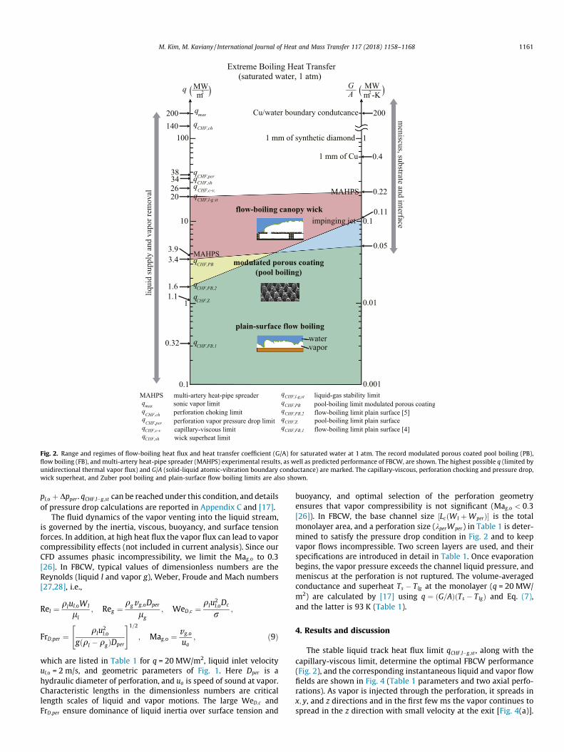
Fig. 2. Range and regimes of flow-boiling heat flux and heat transfer coefficient (G/A) for saturated water at 1 atm. The record modulated porous coated pool boiling (PB),flow boiling (FB), and multi-artery heat-pipe spreader (MAHPS) experimental results, as well as predicted performance of FBCW, are shown. The highest possible q (limited byunidirectional thermal vapor flux) and G/A (solid-liquid atomic-vibration boundary conductance) are marked. The capillary-viscous, perforation chocking and pressure drop,wick superheat, and Zuber pool boiling and plain-surface flow boiling limits are also shown.
M. Kim, M. Kaviany / International Journal of Heat and Mass Transfer 117 (2018) 1158–1168 1161
pl;o þ Dpper . qCHF;l�g;st can be reached under this condition, and detailsof pressure drop calculations are reported in Appendix C and [17].
The fluid dynamics of the vapor venting into the liquid stream,is governed by the inertia, viscous, buoyancy, and surface tensionforces. In addition, at high heat flux the vapor flux can lead to vaporcompressibility effects (not included in current analysis). Since ourCFD assumes phasic incompressibility, we limit the Mag;o to 0.3[26]. In FBCW, typical values of dimensionless numbers are theReynolds (liquid l and vapor g), Weber, Froude and Mach numbers[27,28], i.e.,
Rel ¼ qlul;oWl
ll; Reg ¼
qgvg;oDper
lg; WeD;c ¼
qlu2l;oDc
r;
FrD;per ¼qlu
2l;o
gðql � qgÞDper
" #1=2; Mag;o ¼ vg;o
ua; ð9Þ
which are listed in Table 1 for q = 20 MW/m2, liquid inlet velocityul;o = 2 m/s, and geometric parameters of Fig. 1. Here Dper is ahydraulic diameter of perforation, and ua is speed of sound at vapor.Characteristic lengths in the dimensionless numbers are criticallength scales of liquid and vapor motions. The large WeD;c andFrD;per ensure dominance of liquid inertia over surface tension and
buoyancy, and optimal selection of the perforation geometryensures that vapor compressibility is not significant (Mag;o < 0:3[26]). In FBCW, the base channel size ½LcðWl þWperÞ� is the totalmonolayer area, and a perforation size (kperWper) in Table 1 is deter-mined to satisfy the pressure drop condition in Fig. 2 and to keepvapor flows incompressible. Two screen layers are used, and theirspecifications are introduced in detail in Table 1. Once evaporationbegins, the vapor pressure exceeds the channel liquid pressure, andmeniscus at the perforation is not ruptured. The volume-averagedconductance and superheat Ts � Tlg at the monolayer (q = 20 MW/m2) are calculated by [17] using q ¼ ðG=AÞðTs � TlgÞ and Eq. (7),and the latter is 93 K (Table 1).
4. Results and discussion
The stable liquid track heat flux limit qCHF;l�g;st , along with thecapillary-viscous limit, determine the optimal FBCW performance(Fig. 2), and the corresponding instantaneous liquid and vapor flowfields are shown in Fig. 4 (Table 1 parameters and two axial perfo-rations). As vapor is injected through the perforation, it spreads inx; y, and z directions and in the first few ms the vapor continues tospread in the z direction with small velocity at the exit [Fig. 4(a)].

Table 1The q = 20 MW/m2;ul;o = 2 m/s case with geometric conditions (top row); flow dimensionless numbers (middle row); and pressure drops, thermal conductance and superheat(bottom row). Channel height Hc , perforation distance in x and y directions Wl and Lper , monolayer particle diameter and porosity dm and �m , gas velocity at perforation vg;o, andpermeation liquid velocity at screenlayer v l;o. Other wick parameters are listed in Table B1 of Appendix B. The CFD methods and verification are given in Appendix A.
q (MW/m2) ul;o (m/s) Hc ; Lc (mm) kper ;Wper (mm) Wl; Lper (mm) dm=�m (mm) vg;o=v l;o (m/s) 1=Nper
20 2.0 15,15 5.5,1.5 5.5,1 50/0.40 96.5/0.011 8.5/2Rel Reg WeD;c FrD;per Mag;o ug;o=ul;o ql=qg ll=lg
3:8� 104 1:1� 104 630 13.2 0.25 48 1:6� 103 4:6� 10�2
Dps;l=Dps;$ (kPa) Dpp (kPa) Dpm (kPa) Dpper (kPa) RDpi (kPa) pc;max (kPa) G=A (MW/m2-K) Ts � Tlg (K)0.74/0.026 1.66 13.3 5.8 21.5 21.7 0.22 93
Fig. 3. Pressure distribution of the liquid and vapor phases in the wicks and in the liquid stream. q is reached to the CHF when the total pressure drop is equal to themaximum capillary pressure in the monolayer. The monolayer and perforation pressure drop dominates at high heat flux.
1162 M. Kim, M. Kaviany / International Journal of Heat and Mass Transfer 117 (2018) 1158–1168
After this initial period, the vapor track in the z direction becomesestablished (with time variations), and steady exit vapor flowoccurs. This wavy interface is similar to that observed in plain-surface flow boiling [8,29] and gas-sheared liquid film [30], wheresome vapor track breakdown happen intermittently (induced bythe liquid shear) [Fig. 4(b)]. As shown in Fig. 4(c), at the exit the liq-uid track area Al and width wl in yz plane are clearly observable.The wl and Al are the width and cross-section area of the liquidtrack over the screenlayer unit cell, and wl is along the y-direction at z ¼ 0, and Al is in the yz-plane and varies with x. Forul;o = 2 m/s, the droplets entrained at the vapor interface can beseen [Fig. 4(c)], similar to [30]. Droplet ligaments are also formedbetween two neighboring fast vapor tracks similar to gas-shearedliquid film [30]. These phenomena are observed in the Video (clickhere, https://www.youtube.com/watch?v=xPsdDc3d-gg&feature=youtu.be). These entrained droplets join the liquid track and assistin liquid supply to the wick. In plain-surface flow-boiling, theliquid supply is obstructed by vapor blanket grown from bubblesand cause dryout [31], and FBCW defer this by marinating thenarrow, periodic liquid track reaching much higher dryout limit(q = 20 MW/m2). In the channel, there are two vapor track regimes;one is an isolated-vapor track, and the other is an oscillation trackwhich has both isolated- and merged- vapor tracks. The isolated-vapor track is a state where vapor tracks have streamwise continu-ity while not being merged with adjacent vapor tracks. In themerged-vapor tracks, vapor tracks are combined laterally. Thesetwo types of vapor track regimes are marked in Fig. 4.
In selecting the perforation geometry, we first note that theoptimal unit cell for perforation needs to match the wick unit cell
formed by the posts. The periodic liquid tracks are formed alongthe x direction and within the perforation separation distance Wl
shown in inset of Fig. 5. The variation of the time-averaged liquidtrack width wl and cross-section area Al as a function of Wl forthe conditions in Table 1 are shown in this figure. For Wl < 2.5mm no stable liquid track is formed, while for Wl > 5.5 mm theperforation flow area is reduced such that the vapor compressibil-ity [26] and capillary viscous limits are reached. Within these lim-its, wl and Al increase with Wl. This optimal perforation geometrywould result in the large liquid track width and area to ensurestable liquid supply, and this is the geometry used in thesimulation.
Fig. 6(a) and (b) shows the predicted temporal variations of Al
and wl, at three streamwise locations, for q = 20 MW/m2 and ul;o
= 2 m/s with the snapshots of the liquid profile. For guiding conve-nience, shaded bands are marked to show the trends and continu-ous liquid track (along x and z directions). At the upstream of theexit, the vapor tracks emerging from the perforations remain iso-lated and separated by the liquid track extending to the top ofthe channel. With increase in x, the vapor track oscillates betweenthe isolated and merged states, while the liquid track remains con-tinuous liquid supply to the screenlayer. For formation of stream-wise continuous liquid track between perforations, the liquidinertia should overcome the lateral vapor spreading, which in turndepends on the vapor inertia through the perforation. In additionto streamwise (x), the liquid track continuity in vertical (z) direc-tion (larger Al) improves the liquid supply. So, as the coverage ofisolated vapor track increases, the FBCW has improved irrigationfor higher heat flux of qCHF;l�g;st (= 20 MW/m2). For comparison with

Fig. 4. Instantaneous void-fraction distribution and velocity fields at (a) t = 0.65, (b) 5, and (c) 27.5 ms, for two axial perforations, 20 MW/m2 and 2 m/s. Cross-sectional flowfields (xz and yz planes) at different x and y positions are also shown. The video can be found here (https://www.youtube.com/watch?v=xPsdDc3d-gg&feature=youtu.be).
Fig. 5. Variations of the time-average liquid track width and cross-section area, at three x locations, with respect to the perforation separation distance and for conditionslisted in Table 1. The other perforation parameters are also shown. To the left no stable liquid track is formed, and to the right the compressibility or the capillary-viscouslimits are reached.
M. Kim, M. Kaviany / International Journal of Heat and Mass Transfer 117 (2018) 1158–1168 1163
Fig. 6(a) and (b), the results for q = 20 MW/m2 and ul;o = 1 m/s areshown in Fig. 6(c) and (d). For lower ul;o the isolated-vapor trackregime is less sustainable, and at x = 7.5 mm, the z-direction conti-nuity breaks down. At x = 15 mm, during the most of the time(greater than 90% of time), there is merged-vapor track state (withsmaller z-direction extension), which is in the oscillation regime.
The optimal condition for continuous liquid track in x and zdirections is determined from the Rel and Reg , giving a thresholdliquid velocity ul;o, for while satisfying the compressibility require-ment. Also considering the role of viscosities, and large WeD;c andFrD;per (Table 1), Rel/Reg controls the fate of the liquid track continu-ity and stability. Fig. 7 shows the extent of isolated-vapor track
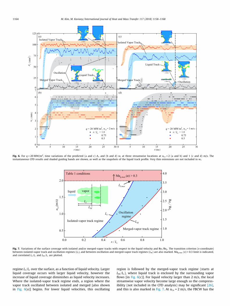
Fig. 6. For q = 20 MW/m2, time variations of the predicted (a and c) Al , and (b and d) wl at three streamwise locations at ul;o = 2 (a and b) and 1 (c and d) m/s. Theinstantaneous CFD results and shaded guiding bands are shown, as well as the snapshots of the liquid track profile. Very thin extensions are not included in wl .
Fig. 7. Variations of the surface coverage with isolated and/or merged-vapor tracks with respect to the liquid velocity and Rel=Reg . The transition criterion (x-coordinate)between isolated-vapor track and oscillation regimes (LI), and between oscillation and merged-vapor track regimes (LM) are also marked. Mag;max (x) > 0.3 limit is indicated,and correlated LI=Lc and LM=Lc are plotted.
1164 M. Kim, M. Kaviany / International Journal of Heat and Mass Transfer 117 (2018) 1158–1168
regime LI=Lc over the surface, as a function of liquid velocity. Largerliquid coverage occurs with larger liquid velocity, however theincrease of liquid coverage diminishes as liquid velocity increases.Where the isolated-vapor track regime ends, a region where thevapor track oscillated between isolated and merged [also shownin Fig. 6(a)] begins. For lower liquid velocities, this oscillating
region is followed by the merged-vapor track regime (starts atLM=Lc), where liquid track is enclosed by the surrounding vaporflows [in Fig. 6(c)]. For liquid velocity larger than 2 m/s, the localstreamwise vapor velocity become large enough so the compress-ibility (not included in the CFD analysis) may be significant [26],and this is also marked in Fig. 7. At ul;o = 2 m/s, the FBCW has the

M. Kim, M. Kaviany / International Journal of Heat and Mass Transfer 117 (2018) 1158–1168 1165
largest extent of isolated-vapor track regimes (LI;max) under thevapor compressibility limit. From the saturated, plain-surfaceforced correlation [32], qCHF;FB is
qCHF;FB
qlulDhlg� qg
ql
� �1=2
We�1=4L;c ; ð10Þ
where Lc is the characteristic length of the Weber number. UsingLi=Lc (i = I, M), we start with
qFBCW
qlulDhlg� Li
Lc
� ��a
; ð11Þ
and CHF occurs when bubble crowding completely covers the sur-face [29,31] corresponding to the merged-vapor track in FBCW.However, in FBCW, liquid track can be sustained beneath the vaporblanket by screenlayer perforation separation and capillarity, withliquid-gas stability limit of FBCW qCHF;l�g;st > qCHF;FB. In the FBCW,qFBCW ¼ qgugDhlgNperkperWper=LcðWper þWlÞ,. With a = 1 and usingEqs. (10) and (11), we suggest (i ¼ L;M)
LiLc
¼ ciRelReg
qg
ql
� �1=2
We�1=4L;c � Am
NperkperWper
ll
lg
Dper
Wl; ð12Þ
with coefficient ci fitted with the least squares method to thenumerical results in Fig. 7, which are 0.37(cI) and 0.54 (cM). TheCFD methods and verification are described in Appendix A.
5. Conclusions
We have shown that FBCW, a boiling metamedium, enablesextreme heat transfer by controlling heat transfer/vapor genera-tion and hydrodynamics of the vapor and liquid tracks. FBCWseparates and directs these tracks to ensure the highest liquid sup-ply rate and smallest thermal resistance. Heat flux up to 0.1qmax ispredicted, and the increase of the liquid velocity extends the
Fig. A1. Variations of key quantities, namely the time-averaged liquid track width and acomputational cells, for q = 20 MW/m2 and ul;o = 2 m/s. The results show using 105 cells
isolated-vapor track coverage, and gradually leads to the stream-wise local vapor compressibility limit. The FBCW transforms boil-ing heat transfer using unit-cell, 3-D capillary structure undersaturated liquid flow and is capable of achieving record fractionof the theoretical maximum heat flux limit.
Conflict of interest
None declared.
Acknowledgment
This work is supported by NSF – USA (Thermal Transport andProcesses, CBET16235720).
Appendix A. CFD Methods
The liquid supply and monolayer evaporation are modeled asdescribed in [17], using numerical solutions to (i) the point-wiseNavier–Stokes and energy equations and the principles of menis-cus minimum-surface energy, and (ii) local volume-averagemomentum and energy equations in the porous media. Here thetwo-phase channel flow is solved using ANSYS FLUENT with thevolume of fluid (VOF) method [33] under incompressibility, i.e.,solving [34,35]
@q@t
þr � u ¼ 0 ðA1Þ@
@tðquÞ þ r � ðquuÞ ¼ �rpþr � ½lðruþruTÞ� þ qgþ fs; ðA2Þ
with velocity u, pressure p, surface tension force fs, and mixturedensity q and dynamic viscosity l. The liquid-gas mixture is treatedas compressible while each phase is assumed as incompressible.The vapor volume fraction a equation and mixture properties are
rea, and cross-section and time-averaged void fraction, as a function of number ofwould lead to no mesh-size dependence.
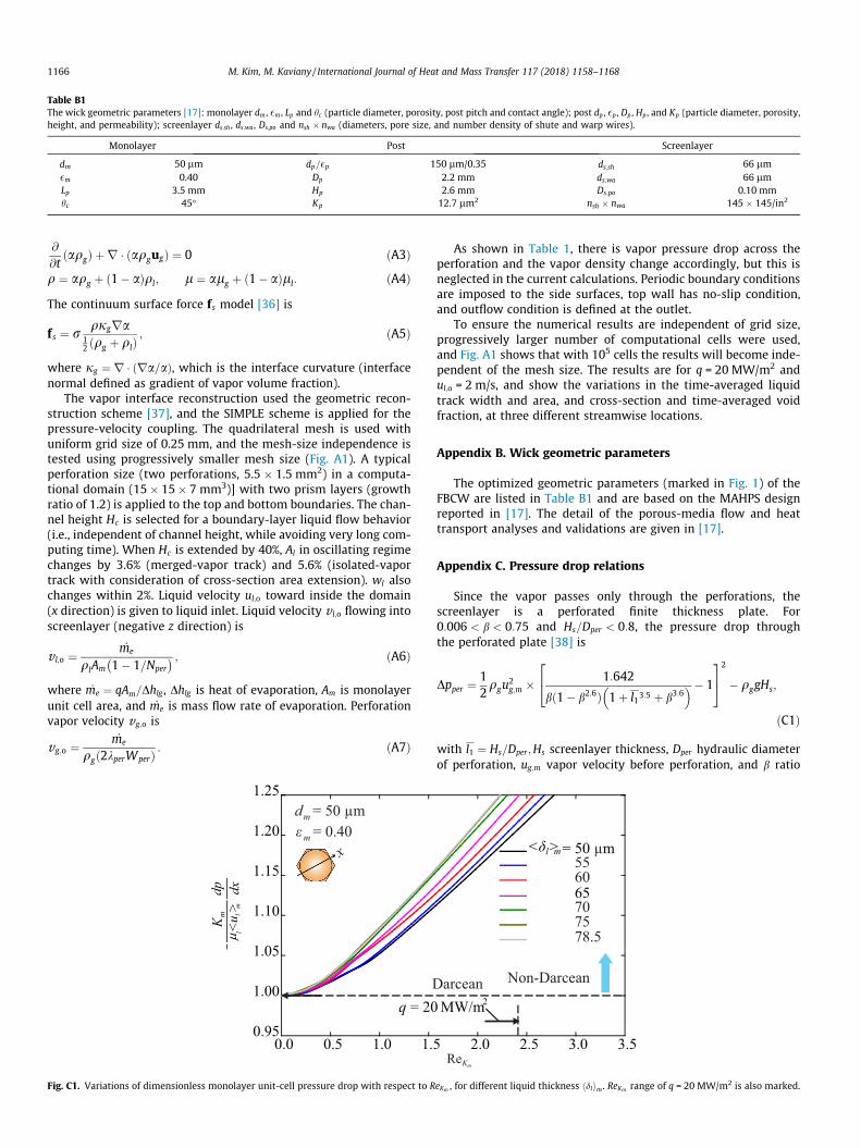
Table B1The wick geometric parameters [17]: monolayer dm , �m , Lp and hc (particle diameter, porosity, post pitch and contact angle); post dp , �p , Dp , Hp , and Kp (particle diameter, porosity,height, and permeability); screenlayer ds;sh , ds;wa , Ds;po and nsh � nwa (diameters, pore size, and number density of shute and warp wires).
Monolayer Post Screenlayer
dm 50 lm dp=�p 150 lm/0.35 ds;sh 66 lm�m 0.40 Dp 2.2 mm ds;wa 66 lmLp 3.5 mm Hp 2.6 mm Ds;po 0.10 mmhc 45� Kp 12.7 lm2 nsh � nwa 145 � 145/in2
1166 M. Kim, M. Kaviany / International Journal of Heat and Mass Transfer 117 (2018) 1158–1168
@
@tðaqgÞ þ r � ðaqgugÞ ¼ 0 ðA3Þ
q ¼ aqg þ ð1� aÞql; l ¼ alg þ ð1� aÞll: ðA4ÞThe continuum surface force fs model [36] is
fs ¼ r qjgra12 ðqg þ qlÞ
; ðA5Þ
where jg ¼ r � ðra=aÞ, which is the interface curvature (interfacenormal defined as gradient of vapor volume fraction).
The vapor interface reconstruction used the geometric recon-struction scheme [37], and the SIMPLE scheme is applied for thepressure-velocity coupling. The quadrilateral mesh is used withuniform grid size of 0.25 mm, and the mesh-size independence istested using progressively smaller mesh size (Fig. A1). A typicalperforation size (two perforations, 5.5 � 1.5 mm2) in a computa-tional domain (15� 15� 7 mm3)] with two prism layers (growthratio of 1.2) is applied to the top and bottom boundaries. The chan-nel height Hc is selected for a boundary-layer liquid flow behavior(i.e., independent of channel height, while avoiding very long com-puting time). When Hc is extended by 40%, Al in oscillating regimechanges by 3.6% (merged-vapor track) and 5.6% (isolated-vaportrack with consideration of cross-section area extension). wl alsochanges within 2%. Liquid velocity ul;o toward inside the domain(x direction) is given to liquid inlet. Liquid velocity v l;o flowing intoscreenlayer (negative z direction) is
v l;o ¼ _me
qlAm 1� 1=Nper� � ; ðA6Þ
where _me ¼ qAm=Dhlg , Dhlg is heat of evaporation, Am is monolayerunit cell area, and _me is mass flow rate of evaporation. Perforationvapor velocity vg;o is
vg;o ¼ _me
qgð2kperWperÞ : ðA7Þ
Fig. C1. Variations of dimensionless monolayer unit-cell pressure drop with respect to R
As shown in Table 1, there is vapor pressure drop across theperforation and the vapor density change accordingly, but this isneglected in the current calculations. Periodic boundary conditionsare imposed to the side surfaces, top wall has no-slip condition,and outflow condition is defined at the outlet.
To ensure the numerical results are independent of grid size,progressively larger number of computational cells were used,and Fig. A1 shows that with 105 cells the results will become inde-pendent of the mesh size. The results are for q = 20 MW/m2 andul;o = 2 m/s, and show the variations in the time-averaged liquidtrack width and area, and cross-section and time-averaged voidfraction, at three different streamwise locations.
Appendix B. Wick geometric parameters
The optimized geometric parameters (marked in Fig. 1) of theFBCW are listed in Table B1 and are based on the MAHPS designreported in [17]. The detail of the porous-media flow and heattransport analyses and validations are given in [17].
Appendix C. Pressure drop relations
Since the vapor passes only through the perforations, thescreenlayer is a perforated finite thickness plate. For0:006 < b < 0:75 and Hs=Dper < 0:8, the pressure drop throughthe perforated plate [38] is
Dpper ¼12qgu
2g;m � 1:642
bð1� b2:6Þ 1þ l13:5 þ b3:6� � 1
24
35
2
� qggHs;
ðC1Þ
with l1 ¼ Hs=Dper ;Hs screenlayer thickness, Dper hydraulic diameterof perforation, ug;m vapor velocity before perforation, and b ratio
eKm , for different liquid thickness hdlim. ReKm range of q = 20 MW/m2 is also marked.
M. Kim, M. Kaviany / International Journal of Heat and Mass Transfer 117 (2018) 1158–1168 1167
of perforation area to area before it. Idelchik [39] suggested anotherempirical correlation
Dpper ¼qgu
2g;m
2b2
ð1� bÞ0:752
þ ð2:4� l1Þl2 ð1� bÞ1:375 þ ð1� bÞ2 þ f l1
" #
� qggHs;
ðC2Þwith l2 and friction coefficient f as
l2 ¼ 0:25þ 0:535l18
0:05þ l17
!; f ¼ 0:316
Re0:25g
: ðC3Þ
In Eqs. (C1)–(C3), the hydrostatic pressure drop by gravitationalforce is also included, and both correlations give very close results.
In [17], the monolayer with closely hexagonal-packed particlesdm = 50 lm and �m = 0.40 gives optimal performance over a rangeof heat flux, and this geometry is also adopted in this study. Usingthe minimum-surface energy principle, the meniscus topology isobtained using the Surface Evolver. Since the monolayer Weber
number Wem ¼ qlhuli2mhdlim=r and capillary number Cam ¼llhulim=r are small, so the static meniscus is used. Detailedprocesses and results are explained in [17]. In the monolayer, forlow heat flux, the liquid Reynolds number Rel;m � 1, and pressuredrop Dpl;m varies linearly with velocity hulim (Darcean flow). ForRel;m of Oð1Þ at high heat flux used here, the so-called Forchheimer(non-Darcean) range, the quadratic hulim term [40–43] for Dpl;m ispresented with the permeability-based Reynolds number ReKm =qlhulimK1=2
m =ll
� Km
llhulimdpl;m
dx¼ cF;1 þ cF;2ReKm ; ðC4Þ
with dpl;m=dx liquid pressure gradient, and Km permeability. Thedimensionless pressure gradient across the unit cell shown inFig. C1 is calculated by ANSYS FLUENT, and covers the Darcy andForchheimer regimes. Here CF;1 = 1 as used in [44,41,43], and forgiven range of Rel;m;CF;2 is comparable to empirical results fromexperiments [45,44,40]. The results show that the meniscus liquidfilm thickness hdlim influences CF;2 under laminar flow condition(monolayer Reynolds number Rel;m < 200) [40].
Appendix D. Supplementary material
Supplementary data associated with this article can be found, inthe online version, at https://doi.org/10.1016/j.ijheatmasstransfer.2017.10.079. The video can be found here (https://www.youtube.com/watch?v=xPsdDc3d-gg&feature=youtu.be).
References
[1] G.S. Hwang, Y. Nam, E. Fleming, P. Dussinger, Y.S. Ju, M. Kaviany, Multi-arteryheat pipe spreader: experiment, Int. J. Heat Mass Transfer 53 (13-14) (2010)2662–2669, https://doi.org/10.1016/j.ijheatmasstransfer.2010.02.046.
[2] S.G. Liter, M. Kaviany, Pool-boiling CHF enhancement by modulated porous-layer coating: theory and experiment, Int. J. Heat Mass Transfer 44 (22) (2001)4287–4311, https://doi.org/10.1016/S0017-9310(01)00084-9.
[3] D. Cooke, S.G. Kandlikar, Effect of open microchannel geometry on pool boilingenhancement, Int. J. Heat Mass Transfer 55 (4) (2012) 1004–1013, https://doi.org/10.1016/j.ijheatmasstransfer.2011.10.010.
[4] Z.G. Qu, Z.G. Xu, C.Y. Zhao, W.Q. Tao, Experimental study of pool boiling heattransfer on horizontal metallic foam surface with crossing and single-directional V-shaped groove in saturated water, Int. J. Multiph. Flow 41(2012) 44–55, https://doi.org/10.1016/j.ijmultiphaseflow.2011.12.007.
[5] C.M. Patil, S.G. Kandlikar, Pool boiling enhancement through microporouscoatings selectively electrodeposited on fin tops of open microchannels, Int. J.Heat Mass Transfer 79 (2014) 816–828, https://doi.org/10.1016/j.ijheatmasstransfer.2014.08.063.
[6] A. Jaikumar, S.G. Kandlikar, Ultra-high pool boiling performance and effect ofchannel width with selectively coated open microchannels, Int. J. Heat Mass
Transfer 95 (2016) 795–805, https://doi.org/10.1016/j.ijheatmasstransfer.2015.12.061.
[7] S. Mori, Y. Utaka, Critical heat flux enhancement by surface modification in asaturated pool boiling: a review, Int. J. Heat Mass Transfer 108 (2017) 2534–2557, https://doi.org/10.1016/j.ijheatmasstransfer.2017.01.090.
[8] J.C. Sturgis, I. Mudawar, Critical heat flux in a long, rectangular channelsubjected to one-sided heating-I. Flow visualization, Int. J. Heat Mass Transfer42 (10) (1999) 1835–1847, https://doi.org/10.1016/S0017-9310(98)00274-9.
[9] D.D. Hall, I. Mudawar, Critical heat flux (CHF) for water flow in tubes-I.Subcooled CHF correlations, Int. J. Heat Mass Transfer 43 (14) (2000) 2605–2640, https://doi.org/10.1016/S0017-9310(99)00192-1. <http://www.sciencedirect.com/science/article/pii/S0017931099001921>.
[10] L. Wang, A.R. Khan, N. Erkan, H. Gong, K. Okamoto, Critical heat fluxenhancement on a downward face using porous honeycomb plate insaturated flow boiling, Int. J. Heat Mass Transfer 109 (2017) 454–461,https://doi.org/10.1016/j.ijheatmasstransfer.2017.01.113.
[11] S.G. Lee, M. Kaviany, C.-J. Kim, J. Lee, Quasi-steady front in quench subcooled-jet impingement boiling: experiment and analysis, Int. J. Heat Mass Transfer113 (2017) 622–634.
[12] M. Kaviany, Principles of Convective Heat Transfer, second ed., Springer, NewYork, 2001.
[13] R.W. Schrage, A Theoretical Study of Interface Mass Transfer, ColumbiaUniversity Press, New York, 1953.
[14] G. Standart, Z. Cihla, Interphase transport processes. I. Schrage’s theories,Collect. Czechosl. Chem. Commun. 23 (1958) 1608–1618.
[15] W.R. Gambill, J.H. Lienhard, An upper bound for the critical boiling heat flux,ASME J. Heat Transfer 111 (August) (1989) 815–818.
[16] D.W. Green, R.H. Perry, Perry’s Chemical Engineers’ Handbook, eighth ed.,McGraw-Hill, New York, 2007.
[17] M. Kim, M. Kaviany, Multi-artery heat-pipe spreader: monolayer-wickreceding meniscus transitions and optimal performance, Int. J. Heat MassTransfer 112 (2017) 343–353.
[18] S. Chi, Heat Pipe Theory and Practice: A Sourcebook, Hemisphere PublishingCoporation, Washington, 1976.
[19] G.P. Peterson, An Introduction to Heat Pipes: Modeling, Testing, andApplications, John Wiley, Inc., New York, 1994.
[20] P.D. Dunn, D.A. Reay, Heat Pipes, Pergamon, New York, 1982.[21] G.S. Hwang, E. Fleming, B. Carne, S. Sharratt, Y. Nam, P. Dussinger, Y.S. Ju, M.
Kaviany, Multi-artery heat-pipe spreader: lateral liquid supply, Int. J. HeatMass Transfer 54 (11–12) (2011) 2334–2340, https://doi.org/10.1016/j.ijheatmasstransfer.2011.02.029.
[22] M. Kaviany, Heat Transfer Physics, second ed., Cambridge University Press,New York, 2014.
[23] M.E. Caplan, A. Giri, P.E. Hopkins, Analytical model for the effects of wetting onthermal boundary conductance across solid/classical liquid interfaces, J. Chem.Phys. 140 (15) (2014) 154701.
[24] T. Vo, B. Kim, Interface thermal resistance between liquid water and variousmetallic surfaces, Int. J. Precis. Eng. Manuf. 16 (7) (2015) 1341–1346, https://doi.org/10.1007/s12541-015-0176-0.
[25] J.H. Lienhard, A. Khounary, Liquid jet impingement cooling with diamondsubstrates for extremely high heat flux applications, in: Proceedings of SPIE’sInternational Symposium on Optics, Imaging, and Instrumentation, vol. 1997,San Diego, 1993.
[26] F. White, Fluid Mechanics, seventh ed., McGraw-Hill, New York, 2011.[27] Y. Murai, Frictional drag reduction by bubble injection, Exp. in Fluids 55 (7)
(2014) 1773.[28] D. Kim, P. Moin, Direct Numerical Study of Air Layer Drag Reduction
Phenomenon Over a Backward-Facing Step, Tech. rep., Center for TurbulenceReserach, Stanford University, 2010.
[29] C. Konishi, I. Mudawar, M.M. Hasan, Investigation of localized dryout versusCHF in saturated flow boiling, Int. J. Heat Mass Transfer 67 (2013) 131–146,https://doi.org/10.1016/j.ijheatmasstransfer.2013.07.082.
[30] A.V. Cherdantsev, D.B. Hann, B.J. Azzopardi, Study of gas-sheared liquid film inhorizontal rectangular duct using high-speed LIF technique: three-dimensional wavy structure and its relation to liquid entrainment, Int. J.Multiph. Flow 67 (2014) 52–64, https://doi.org/10.1016/j.ijmultiphaseflow.2014.08.003.
[31] M. Bruder, G. Bloch, T. Sattelmayer, Critical heat flux in flow boiling-review ofthe current understanding and experimental approaches, Heat Transfer Eng.38 (3) (2017) 347–360, https://doi.org/10.1080/01457632.2016.1189274.
[32] Y. Katto, C. Kurata, Critical heat flux of saturated convective boiling onuniformly heated plates in a parallel flow, Int. J. Multiph. Flow 6 (6) (1980)575–582, https://doi.org/10.1016/0301-9322(80)90052-X.
[33] C.W. Hirt, B.D. Nichols, Volume of fluid (VOF) method for the dynamics of freeboundaries, J. Comput. Phys. 39 (1) (1981) 201–225.
[34] E. Delnoij, J.A.M. Kuipers, W.P.M. van Swaaij, Computational fluid dynamicsapplied to chemical reaction engineering, Adv. Chem. Eng. 24 (97) (1998)227–328.
[35] D. Ma, M. Liu, Y. Zu, C. Tang, Two-dimensional volume of fluid simulationstudies on single bubble formation and dynamics in bubble columns, Chem.Eng. Sci. 72 (2012) 61–77, https://doi.org/10.1016/j.ces.2012.01.013.
[36] J.U. Brackbill, D.B. Kothe, C. Zemach, A continuum method for modelingsurface tension, J. Comput. Phys. 100 (2) (1992) 335–354, https://doi.org/10.1016/0021-9991(92)90240-Y.
[37] D.L. Youngs, Numerical Methods for Fluid Dynamics, Academic Press, NewYork, 1982.
1168 M. Kim, M. Kaviany / International Journal of Heat and Mass Transfer 117 (2018) 1158–1168
[38] A.J. Ward-Smith, Internal Fluid Flow, Clarendon Press, Oxfod, 1980.[39] I.E. Idelchik, Handbook of Hydraulic Resistance, third ed., CRC Press, Florida,
1994.[40] R.M. Fand, B.Y.K. Kim, A.C.C. Lam, R.T. Phan, Resistance to the flow of fluids
through simple and complex porous media whose matrices are composed ofrandomly packed spheres, J. Fluids Eng. 109 (3) (1987) 274, https://doi.org/10.1115/1.3242660.
[41] I. Kececioglu, Y. Jiang, Flow through porous media of packed spheres saturatedwith water, J. Fluids Eng. 116 (1) (1994) 164–176, https://doi.org/10.1115/1.2910229. <http://www.osti.gov/energycitations/product.biblio.jsp?osti_id=7113838%5Cnhttp://apps.isiknowledge.com/InboundService.do?product=WOS&action=retrieve&SrcApp=AIP&UT=A1994NE37400026&SID=W2O1hGleDhnFM@O3jhf&mode=FullRecord&DestFail=http://www.isiknowledge.com>.
[42] M. Kaviany, Principles of Heat Transfer in Porous Media, second ed., SpringerNew York, New York, 1995, https://doi.org/10.1007/978-1-4612-4254-3.<http://link.springer.com/book/10.1007%2F978-1-4612-4254-3>.
[43] J.L. Lage, B.V. Antohe, D.A. Nield, Two types of nonlinear pressure-drop versusflow-rate relation observed for saturated porous media, J. Fluids Eng. 119 (3)(1997) 700–706, https://doi.org/10.1115/1.2819301. <http://link.aip.org/link/?JFG/119/700/1>.
[44] I.F. Macdonald, M.S. El-Sayed, K. Mow, F.A.L. Dullien, Flow through porousmedia-the Ergun equation revisited, Ind. Eng. Chem. Fund. 18 (3) (1979) 199–208, https://doi.org/10.1021/i160071a001. <http://pubs.acs.org/doi/abs/10.1021/i160071a001>.
[45] S. Ergun, Fluid flow through packed columns, Chem. Eng. Prog. 48 (1952) 89–94.