international journal of heat and mass...
TRANSCRIPT

International Journal of Heat and Mass Transfer 60 (2013) 163–169
Contents lists available at SciVerse ScienceDirect
International Journal of Heat and Mass Transfer
journal homepage: www.elsevier .com/locate / i jhmt
Planar vapor chamber with hybrid evaporator wicks for the thermal managementof high-heat-flux and high-power optoelectronic devices
Y. Sungtaek Ju a,⇑, M. Kaviany b, Y. Nam a,c, S. Sharratt a, G.S. Hwang b, I. Catton a, E. Fleming d, P. Dussinger d
a University of California, Los Angeles, CA, USAb University of Michigan, Ann Arbor, MI, USAc Kyung Hee University, Yongin, Republic of Koread Advanced Cooling Technologies Inc., PA, USA
a r t i c l e i n f o
Article history:Received 17 July 2012Received in revised form 30 November 2012Accepted 27 December 2012
Keywords:Vapor chamberHeat pipeEvaporatorWickPhase change heat transfer
0017-9310/$ - see front matter � 2013 Elsevier Ltd. Ahttp://dx.doi.org/10.1016/j.ijheatmasstransfer.2012.12
⇑ Corresponding author. Address: 420 Westwood P1597, USA. Tel.: +1 310 825 0985; fax: +1 310 206 23
E-mail address: [email protected] (Y.S. Ju).
a b s t r a c t
Heat spreaders based on compact vapor chambers offer one attractive approach to the thermal manage-ment of high-power electronics. We report our design and experimental characterization of advancedevaporator wicks and thin planar vapor chambers incorporating these wicks. The hybrid wicks combinedistributed high-permeability liquid supply structures with thin (monolayer) evaporation layers toachieve both low thermal resistance and high limiting heat fluxes over large heating areas. We modeland experimentally characterize the capillary and heat transfer performance of liquid spreading layersconsisting of mono-layers of Cu particles and identify a range of optimal particle diameters maximizingtheir performance. The thin liquid spreading layers are integrated with three different types of liquid sup-ply structures, namely, columnar arteries, converging lateral arteries, and bi-porous structures. Theresulting hybrid wicks show comparable heat transfer performances with critical limiting heat fluxes>350 W/cm2 over heating areas of 1 cm2 and peak heat transfer coefficients >20 W/cm2 K. These resultsconfirm the effectiveness of our hybrid wick designs and also that evaporation heat transfer is dominatedby the liquid spreading layers. A prototype vapor chamber incorporating CTE-tailored envelopes and thehybrid wick is developed for potential applications in the thermal management of laser diode arrays. Wedemonstrate an evaporator resistance of approximately 0.075 K/(W/cm2), while removing over 1500 Wfrom a 4 cm2 heating area.
� 2013 Elsevier Ltd. All rights reserved.
1. Introduction
Advanced high-power and high-power-density electronic andoptoelectronic devices very often require innovative thermal man-agement solutions to ensure their reliable operations. One attrac-tive approach is to passively spread the thermal energy over alarge area using a thin planar vapor chamber before it reaches adownstream heat sink. This helps circumvent various reliabilitychallenges of high-performance cooling solutions based on micro-channels, such as corrosion or erosion of channel walls, pump fail-ures, and various modes of flow instabilities (for two-phase flowcooling).
The thermal resistance of vapor chambers is most often domi-nated by that of the evaporators. Thin evaporator wicks with higheffective thermal conductivity are desired to reduce the evaporatorthermal resistance. Such thin wicks, however, suffer from low crit-ical limiting heat fluxes due to their large liquid hydraulic resis-
ll rights reserved..058
laza, Los Angeles, CA 90095-02.
tances. These two conflicting considerations present significantchallenges in designing effective evaporator wicks for handlinglarge arrays of high-heat flux devices, such as laser diodes andRF/MW amplifiers.
Previous studies reported various wick structures developed forthin vapor chambers [1–4]. These past wick designs, however,were limited to small heating regions (�1 cm2) or relatively lowheat fluxes (<100 W/cm2).
We report our efforts in developing hybrid wick structureswhere we integrate a thin liquid spreading layer with separate li-quid supply structures to achieve an optimal balance between asmall wick thermal resistance and a high critical limiting heat flux.Our previous work [5,6] discussed modeling of the liquid supplystructures for one fixed liquid spreading layer design. We discusshere our efforts to optimize the capillary and heat transfer perfor-mance of monolayers of sintered Cu particles for use as liquidspreading layers. Heat transfer performance of various hybridwicks that integrate the optimized liquid spreading layers with dif-ferent types of liquid supply structures is next compared.
Vapor chambers for electronics cooling have typically beenmanufactured using copper or aluminum, which require compliant

164 Y.S. Ju et al. / International Journal of Heat and Mass Transfer 60 (2013) 163–169
interface materials like thermal greases and pads to accommodatemismatch in the coefficient of thermal expansion with electronicor optoelectronic devices. As device heat flux increases, most exist-ing thermal interface materials are no longer effective due to theirrelatively low thermal conductivity. Direct chip bonding is farsuperior from a thermal resistance point of view but is more proneto failures by thermomechanical stress. We also report the design,fabrication, and experimental characterization of a prototype pla-nar vapor chamber incorporating our hybrid wick on envelopeswhose coefficient of thermal expansion (CTE) has been tailoredto closely match laser diodes.
2. Hybrid wick designs
The basic design philosophy of our hybrid evaporator wicks is toseparate the liquid supply function from the heat transfer function.Fig. 1 schematically illustrates three types of hybrid wicks thatincorporate different liquid supply structures: (a) an array of verti-cal columnar arteries [5], (b) converging lateral finger-like arteries[6], and (c) a bi-porous structure of sintered particles [7].
The thin liquid spreading layer can be either a monolayer of sin-tered metal particles or an array of microfabricated posts with higheffective thermal conductivity. Its thinness enables us to achievevery high evaporator heat transfer coefficient. The liquid supplystructure sits on top of the liquid spreading layer to deliver liquidat multiple spots over an evaporator surface. This distributed liquiddelivery scheme enables the liquid to spread efficiently along thespreading layer and keep a large evaporator surface wetted evenat very high heat fluxes. The vapor generated through evaporationof the liquid layer readily escapes through large ‘‘pores’’ (space be-tween arteries or particle clusters), reducing pressure drop for va-por flows.
Vertical columnar arteseir suorop-ibderedwoPstructures
Converging lateral arteries
Liquid spreading layers1 cm
Fig. 1. Three different hybrid wicks considered in the present study with differenttypes of liquid supply structures: vertical columnar arteries (side view), converginglateral arteries (top view), and bi-porous structures (side view).
3. Modeling and characterization of liquid spreading layers
Our previous publications reported detailed modeling andexperimental studies of one type of thin liquid spreading layers:arrays of microfabricated Cu posts of heights of the order of100 lm [8,9]. The geometric parameters of such micro-posts areprecisely defined, facilitating the validation of theoretical modelsfor their capillary and heat transfer performance.
An alternative option is monolayers of sintered metal particles.These monolayers can be fabricated using the same manufacturingprocesses as conventional wicks and therefore be more readilyintegrated with our liquid supply structures. We therefore focuson these monolayers of metal particles in this study.
Many previous studies reported heat transfer characteristics ofsintered Cu particles but mostly for much thicker layers [10,11].Visualization and modeling studies of the meniscus of well-wet-ting evaporating liquids around large macro-scale copper sphereswere also reported [12]. We expand upon this and other work bydeveloping models for their capillary and heat transfer perfor-mance and comparing their predictions with experimental results.
100 µµm
(a) 29 µm (b) 59 µm
Fig. 2. SEM images of monolayers of sintered Cu particles of diffe
3.1. Sample preparation
In the present work, monolayer samples were prepared using aprocess analogous to self-assembly of particles. We first sieve Cuparticles, suspend them in a solvent, and coat the resulting sol-vent–powder mixture on a 500 lm-thick Cu substrate (3 � 3 cmarea). As the solvent is dried off, the particles aggregate and assem-ble on the substrate. The samples are then sintered in a hydrogenfurnace for 1 h at 960 �C.
Samples made of particles of three different average diameterswere studied: 29, 59, and 71 lm. Fig. 2 shows representative SEMimages of these samples. The average powder diameter and distri-bution are determined by analyzing SEM images at multiple loca-tions across the sample surfaces and listed in Table 1. Thestandard deviation in the powder diameter was as high as ±30%for the smallest particles due to limitations of our mechanical siev-ing process.
3.2. Modeling
The shape of a liquid meniscus around each Cu powder is a keyfactor that influences the capillary and heat transfer performance.To help validate, albeit indirectly, our experimental results andgain further physical insight, we construct approximate numericalmodels. We first employ the surface energy minimization algo-rithm to predict the ‘‘static’’ shape of a liquid meniscus for a ‘‘ficti-tious’’ unit cell consisting of a group of four spherical particlesobtained from SEM images (see Fig. 3). ‘‘Random’’ spatial variationsin the powder diameter and the relative powder location over eachsample were not taken into account in this very approximatemodel.
Modeling the so-called thin film/interline region presents sig-nificant computational challenges. We consider an ‘‘apparent’’ con-tact as an adjustable parameter to approximately represent theimpacts of evaporation and interfacial forces on thin evaporatingliquid films and predict the heat transfer coefficient as a functionof this parameter. A similar approach was adopted in our recentstudies [8,9,13].
The particle–substrate contact is also important for both heattransfer (point contact of a spherical particle to the substrate
(c) 71 µm
rent average diameters: (a) 29 lm, (b) 59 lm, and (c) 71 lm.

Table 1Geometric properties of the monolayers of sintered Cu particles.
Average diameter (lm) Standard deviation (lm) Solid fraction (%)
29 8 3559 6 3871 5 37
0 20 40 60 80 100-5
0
5
10
15
20
25
30
Pre
dic
ted
Cap
illar
y P
ress
ure
(kP
a)
Liquid Fill Factor (%)
20° 30° 50°
Fig. 4. Predicted capillary pressure of a monolayer powder sample as a function ofthe liquid fill factor for different values of the apparent contact angle.
Y.S. Ju et al. / International Journal of Heat and Mass Transfer 60 (2013) 163–169 165
would add significant thermal resistance) and capillary pressure.Based on SEM images, we model Cu particles as truncated sphereswith a ratio between the neck radius and the particle radius of 0.3.
The capillary pressure is computed from the surface curvatureof a predicted meniscus profile for different values of the apparentcontact angle and the liquid fill factor. The liquid fill factor servesas a relative measure of the liquid volume and is defined as the rel-ative (with respect to the particle) height a liquid layer of a givenvolume would have if its meniscus were flat.
Representative images of the simulated static menisci areshown in Fig. 3 for different values of the liquid fill factor. Wateris used as the working fluid for all results presented here. The pre-dicted ‘‘static’’ meniscus shapes were imported into finite elementliquid flow models (to predict the permeability, K) and heat trans-fer models (to predict the effective heat transfer coefficient, heff).
For the liquid flow model, the no-slip boundary condition is ap-plied on all the particle and wall surfaces. The symmetry conditionis applied on the side walls of the unit cell. The shear-free bound-ary condition is applied on the liquid meniscus. A periodic bound-ary condition is applied at the inlet and outlet of the unit cell. Theheat transfer model accounts for solid and liquid heat conductionand evaporation at the liquid meniscus surface. Only pure conduc-tion is considered in the heat transfer model as a previous studysuggested that the internal convection has relatively small effects[14,15]. Further details of the models are provided in [8,9,13].
A grid independence study was performed to verify simulationaccuracy. Increasing the number of surface mesh elements by 33%resulted in <1% change in heff. Doubling the number of volumemesh elements in the thin film region also resulted in less than<1% change in heff.
The predicted capillary pressures for a sample with particles ofaverage diameter 59 lm are shown in Fig. 4. The calculated capil-lary pressure first increases with the increasing liquid fill factorand reaches a peak at a liquid fill factor approximately 0.5. This li-quid fill factor value is assumed to correspond to a quasi-equilib-rium location of liquid meniscus. The capillary pressuredecreases with further increase in the liquid fill factor once small-est gaps between neighboring particles become submerged belowthe liquid meniscus.
Previous studies [16] experimentally demonstrated that thecapillary pressure of bulk sintered powder plugs is primarily a
Fig. 3. Representative images of the simulated static m
function of the particle diameter. The predicted peak capillarypressure of the monolayers is comparable to the previous resultsobtained from bulk sintered powder plugs of similar particlediameters.
The permeability is also calculated for different values of theapparent contact angle as a function of the liquid fill factor(Fig. 5). The apparent contact angle has a small overall effect onthe permeability. The apparent contact angle affects permeabilitythrough changes in the shape of the liquid meniscus. At a given li-quid fill factor, smaller apparent contact angles lead to skinniermenisci on particle surfaces (larger flow resistance) but higheroverall meniscus heights (smaller flow resistance). The two factorsoffset each other, resulting in weak dependence of the permeabil-ity on the apparent contact angle.
3.3. Experiments
We performed capillary rate of rise experiments to determinethe capillary performance parameter, which is defined as the ratiobetween the liquid permeability K and the effective pore radiusReff, of the monolayers. This parameter compares the driving force(capillary force) for liquid flows along a liquid spreading layeragainst the hydraulic resistance. It is therefore a key determinantof the capillary limit of the layer. Details of the capillary rate of riseexperiments are discussed in our earlier publication [8]. Briefly, weorient a dry sample vertically and bring its tip into contact with aliquid reservoir below. We optically monitor the location of the
enisci for different values of the liquid fill factor.

20 30 40 50 60 70 800.0
0.1
0.2
0.3
0.4
0.5Prediction (app. contact angle = 20°)Prediction (app. contact angle = 50°)Experiments
Liquid fill factor: 0.5
Cap
illar
y P
erfo
rman
ce P
aram
eter
, K/ R
eff(µ
m)
Average Particle Diameter (µm)
Fig. 6. Predicted and experimentally measured capillary performance of the Cumonolayer samples of different average powder diameters.
166 Y.S. Ju et al. / International Journal of Heat and Mass Transfer 60 (2013) 163–169
advancing meniscus front as a function of time. The time trajectoryis then analyzed to determine the parameter K/Reff that best fits thecapillary rise data.
The heat transfer performance of the monolayers was charac-terized using a thermosyphon-like experimental setup reportedearlier [9]. A thin (�150 lm) silicon or AlN chip containing athin-film serpentine heater (5 � 5 mm) was bonded to the backof each sample. The entire sample assembly is housed in a sealedcopper chamber with ports for a vacuum pump/gauge and a work-ing fluid (water) inlet/outlet. A copper tube connected to a recircu-lating thermal bath is wrapped around the chamber multiple timesto control the chamber temperature. The chamber is designed tocreate a controlled saturated liquid–vapor ambient (saturatedwater at 45 �C for the present work). Small (36 AWG) K-type ther-mocouple beads were bonded on eight different points along thecenterline on the back sides of the substrates. The temperature ofthe thin-film heater was also directly monitored from its electricalresistance. Other details of the setup were reported in [9].
3.4. Results
The experimentally measured capillary performance parame-ters (K/Reff) are compared with the predicted results in Fig. 6. Thecapillary performance parameter increases with the particle diam-eter, due in part to the reduced impact of the substrate on the vis-cous resistance. The improvement becomes modest, however,when the particle diameter is greater than approximately 60 lm.The experimental results are consistent with the predictions fromour approximate model (the liquid fill factor = 0.5). The static con-tact angle of water on clean but slightly oxidized copper surfaceswas approximately 30–50�.
As for heat transfer performance, the measured heat input ver-sus wall superheat data from each sample (Fig. 7) are analyzedusing 3D finite element simulations to account for heat spreadingwithin the heater chip and the substrate. We iteratively search foran ‘‘average’’ heat transfer coefficient, which is assumed to be con-stant over the entire sample front surface, to match the experimen-tal data. We call this the ‘‘effective heat transfer coefficient’’ in thisreport because the local heat transfer coefficient is not constant.The local heat transfer coefficient is expected to vary spatially overthe sample surface as the local meniscus shapes adjust in responseto heating to provide necessary capillary pumping power. Directexperimental confirmation of spatial variations in the meniscuscurvature was reported in [17].
0 20 40 60 800.0
0.5
1.0
Apparent contact angle
Pre
dic
ted
Per
mea
bili
ty (
µ m2 )
Liquid Fill Factor (%)
20°30°
50°
Fig. 5. Predicted liquid permeability of a monolayer powder sample as a function ofthe liquid fill factor for different values of the apparent contact angle.
The experimentally determined effective heat transfer coeffi-cients are approximately 5.5 W/cm2 K for all the samples at heatfluxes approximately <15 W/cm2 K. The values predicted fromthe static meniscus models for apparent contact angles 30–50�range from 5.9 to 6.4 W/cm2 K, consistent with our experimentaldata. Appreciable changes in the heat transfer coefficient occur atheat fluxes as low as �15 W/cm2 for the sample with the smallestparticles and�50 W/cm2 for the samples with bigger particles. Onemust take into account local dry out, bubble nucleation, and otherphase change and flow phenomena to model the heat transfer coef-ficient at these higher heat fluxes.
4. Heat transfer performance of hybrid wicks
Our modeling and characterization study discussed above showthat there exists an optimal range of particle diameter that maxi-mizes the capillary performance of monolayers of sintered Cu par-ticles. We therefore prepared hybrid wicks using liquid spreadinglayers made of Cu particles of target mean diameters of 60 lmfor further characterization.
The heat transfer performance of the three different types of hy-brid wicks was characterized using the experimental configurationillustrated in Fig. 8. Each evaporator wick was sintered on a 1mm � 7 � 12 cm copper plate, which was then brazed onto a sec-ond copper plate via a 2.5 mm-thick copper spacer to achieve her-metic sealing.
For the wick with vertical columnar arteries, meshed copperscreens were bonded to the condenser surface to feed the liquidto the arteries. For the wick with either converging lateral arteriesor bi-porous structures, no separate condenser wick was used. In-stead, a condensate pooled at the bottom of the vapor chambers bygravity is returned to the evaporator via the liquid supplystructures.
Copper particles of nominal diameters 60 ± 5 lm were used toform the lateral arteries and bi-porous structures. Larger(D = 150 lm) particles were used to form the vertical columnararteries. The vertical columnar arteries were 1.5 mm in heightand 2.2 mm in diameter. The pitch was 3.52 mm. Each lateral ar-tery is 1.5 mm thick and 1 mm wide.
A copper heating block incorporating cartridge heaters wasused to apply heating over an area of 1 cm2. A thermocouple wasinserted into a pedestal directly machined onto the left copperplate to determine the heated wall temperature. For heat removal,aluminum water cooled blocks were fastened to the condenser side
0 5 10 15 20 250
20
40
60
80
100
29 µm 59 µm 71 µm
Hea
t F
lux
(W/c
m2 )
Wall Superheat (K)
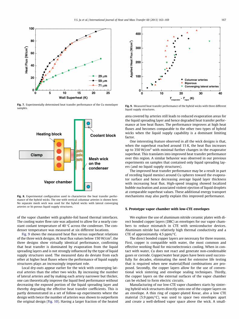
Fig. 7. Experimentally determined heat transfer performance of the Cu monolayersamples.
Clamp
Heating block
Vapor chamber
Coolant block
Mesh wick on the condenser
Fig. 8. Experimental configuration used to characterize the heat transfer perfor-mance of the hybrid wicks. The one with vertical columnar arteries is shown here.No separate mesh wick was used for the hybrid wicks with lateral convergingarteries or bi-porous liquid supply structures.
0 10 20 30 400
100
200
300
400
Columnar arteries Biporous Converging lateral arteries
Ap
plie
d H
eat
Flu
x (W
/cm
2 )
Tevaporator
- Tvapor
(K)
Fig. 9. Measured heat transfer performance of the hybrid wicks with three differentliquid supply structures.
Y.S. Ju et al. / International Journal of Heat and Mass Transfer 60 (2013) 163–169 167
of the vapor chamber with graphite-foil based thermal interfaces.The cooling water flow rate was adjusted to allow for a nearly con-stant coolant temperature of 40 �C across the condenser. The con-denser temperature was measured at six different locations.
Fig. 9 shows the measured heat flux versus superheat relationsof the three wick designs. At heat flux values below 150 W/cm2, thethree designs show virtually identical performance, confirmingthat heat transfer is dominated by evaporation from the liquidspreading layers and is not strongly influenced by the type of liquidsupply structures used. The measured data do deviate from eachother at higher heat fluxes where the performance of liquid supplystructures plays an increasingly important role.
Local dry-outs appear earlier for the wick with converging lat-eral arteries than the other two wicks. By increasing the numberof lateral arteries and by making each artery narrower but thicker,one can theoretically improve the liquid feed performance withoutdecreasing the exposed portion of the liquid spreading layer andthereby degrading the effective heat transfer coefficients. This ispartly demonstrated in a set of follow-up experiments where thedesign with twice the number of arteries was shown to outperformthe original design (Fig. 10). Having a larger fraction of the heated
area covered by arteries still leads to reduced evaporation areas forthe liquid spreading layer and hence degraded heat transfer perfor-mance at low heat fluxes. The performance improves at high heatfluxes and becomes comparable to the other two types of hybridwicks when the liquid supply capability is a dominant limitingfactor.
One interesting feature observed in all the wick designs is that,when the superheat reached around 15 K, the heat flux increasesup to 350 W/cm2 with minimal further changes in the evaporatorsuperheat. This translates into improved heat transfer performanceover this region. A similar behavior was observed in our previousexperiments on samples that contained only liquid spreading lay-ers (and no liquid supply structures).
The improved heat transfer performance may be a result in partof receding liquid menisci around Cu spheres toward the evapora-tor surface and hence decreasing average liquid layer thicknesswith increasing heat flux. High-speed imaging showed localizedbubble nucleation and associated violent ejection of liquid dropletsat comparable superheat values. These additional energy transportmechanisms may also partly explain this improved performance.
5. Prototype vapor chamber with low-CTE envelopes
We explore the use of aluminum nitride ceramic plates with di-rect bonded copper layers (DBC) as envelopes for our vapor cham-bers to reduce mismatch in CTE with semiconductor devices.Aluminum nitride has relatively high thermal conductivity and aCTE of approximately 4.5 ppm/�C.
The direct bonded copper layers are necessary for three reasons.First, copper is compatible with water, the most common andeffective working fluid for microelectronics cooling. When in con-tact with water, Cu does not react and generate non-condensablegases or corrode. Copper/water heat pipes have been used success-fully for decades, eliminating the need for extensive life testingthat is required when new material/fluid combinations are pro-posed. Secondly, the copper layers allow for the use of conven-tional wick sintering and envelope sealing techniques. Thirdly,the copper layers on the external surfaces of the vapor chambercan be etched to form electric circuits.
Manufacturing of our low-CTE vapor chambers starts by sinter-ing hybrid wick structures directly onto one of the copper layers onan envelope. A thin ring of copper-plated Kovar, also a low CTEmaterial (5.9 ppm/�C), was used to space two envelopes apartand create a well-defined vapor space above the wick. A small-

0
100
200
300
400
0 20 40 60
Iteration 1 Iteration 2 Iteration 3
Wall Superheat (K)
Ap
plie
d H
eat
Flu
x (W
/cm
2 )
1 cm x 1 cm heater
Iteration 1: 16 arteries Iteration 2: 16 Arteries Iteration 3: 32 arteries
Fig. 10. Comparison of the heat transfer performance of hybrid evaporator wicks incorporating three different designs of the lateral converging arteries.
Fig. 11. Vapor chamber with etched electrical circuitry and plated gold/gold-tinsolder layers for direct attachment of chips. Also shown is an optical image of thehybrid evaporator wick with laterally converging liquid supply structures specif-ically designed to accommodate 4 VCSELs.
168 Y.S. Ju et al. / International Journal of Heat and Mass Transfer 60 (2013) 163–169
diameter fill tube was brazed into the Kovar ring to allow for evac-uation and fluid charging. Brazing materials with proven compati-bility with water (silver, copper, phosphorous alloys) were used tojoin the envelopes to the Kovar ring, forming the hermetic leak-tight vapor chamber. The brazing temperatures (640–815 �C) arewell above the soldering temperatures (280–325 �C) typically usedto attach electronic or optoelectronic devices. The assembled vaporchambers will therefore not be affected by subsequent chip attach-ment processes.
For reliable operations, one must ensure adequate hemeticity(e.g., less than 0.1% fluid loss per year) of vapor chambers. We useda helium mass spectrometer to measure a leak rate <9 � 10�10 -Std. cc/sec, which may be translated into a fluid loss of 0.00005%/year for an 8 g fluid charge or >10 years of operation with negligi-ble fluid leak. For more direct leak tests, several sealed vaporchambers were placed on burn-in stations maintained at 100 �Cand weighed periodically to check for mass loss. Through thesetests, we observed a weight loss <0.02% over a period of 9744 h.
Fig. 11 shows a 10 � 10 cm prototype specifically designed forpotential application in the thermal management of high-powervertical cavity surface emitting laser (VCSEL) arrays. The top Culayer of the vapor chamber is etched, gold/solder plated for directattachment of VCSEL chips. Microchannel coolers are currentlyused for this application but they are susceptible to various failuremechanisms. Our vapor chambers enable efficient heat spreading,which in turn allows for the use of conventional low-fluid-velocitycold plates as heat sinks. This eliminates the need for costly high-pressure pumps and fluid conditioning equipment associated withmicrochannel coolers.
A hybrid wick specifically designed to accommodate an array offour 1 � 1 cm VCSEL chips is also shown in Fig. 11. Bi-porous liquidsupply structures present challenges for thin and long planar vaporchambers due to the increased need for dedicated vapor space (tocounter large vapor pressure drop) and less flexibility in designing
and manufacturing the wicks around an array of distributed heat-ers. Vertical columnar arrays present challenges in achievingmechanical robustness and providing reliable contacts with con-denser wicks. Based on these considerations, we select the refinedconverging lateral arteries as the liquid supply structures.
A typical set of test data from the prototype vapor chamberswith four separate heater sections is shown in Fig. 12. The vaporchamber evaporator resistance is calculated from the temperaturedifference between a thermocouple inserted in a well drilled intothe heat input pedestal and a thermocouple inserted into a wellthat protrudes into the vapor space and the electrical power inputper square centimeter of the heat input area.
As seen in the plot, the evaporator thermal resistance decreasesas the heat flux increases from 0 to approximately 350 W/cm2,

0 500 1000 1500 20000.00
0.05
0.10
0.15
0.20
Eva
po
rato
r R
esis
tan
ce (
cm2 K
/W)
Power (W)
4 cm2 heating area
Fig. 12. Evaporator thermal resistance measured from a prototype vapor chamberwith a hybrid wick with laterally converging arteries as a function of heat inputpower (four 1 cm � cm heaters).
Y.S. Ju et al. / International Journal of Heat and Mass Transfer 60 (2013) 163–169 169
consistent with the independent tests on the evaporator wicks dis-cussed in Section 4. Above 400 W/cm2, the wick structure begins todry out and the thermal resistance increases until it reaches a crit-ical limiting heat flux of approximately 550 W/cm2. A total powerthrough the vapor chambers of >1500 W was demonstrated with aheat input size of 4 cm2. The evaporator thermal resistance as lowas 0.075 �C/W/cm2 was achieved. Prototypes incorporating hybridwicks with vertical columnar arteries showed comparableperformance.
6. Summary and conclusion
We presented our efforts in developing an innovative vaporchamber concept incorporating hybrid wicks of two integratedstructures: a low thermal resistance spreading layer and a dedi-cated liquid supply structure. The spreading layer is comprised ofa monolayer of sintered Cu particles to minimize the thermal resis-tance in the evaporator. Three different liquid supply structureswere studied: vertical columnar arteries, converging lateral arter-ies, and bi-porous structures. All three designs were demonstratedto be able to handle heat fluxes >350 W/cm2 over heating areas of1 cm2. A detailed modeling and experimental study of the capillaryand heat transfer performance of monolayer liquid spreading lay-ers was conducted to identify a range of optimal particle diame-ters. Hybrid wicks incorporating the three different liquid supplystructures show virtually identical performance, confirming thatheat transfer is dominated by evaporation from the liquid spread-ing layers.
We further established effective vapor chamber solutions foradvanced chip layouts using low-CTE envelope materials. Theseenvelope materials should allow the use of high thermal conduc-tivity solders for direct attachments of semiconductor devices, fur-ther reducing overall thermal resistance. The work presented here
can be utilized to develop high performance cooling solutions forhigh-power and high-power-density electronic components.
Acknowledgment
This work was supported in part by the Defense Advanced Re-search Project Agency (DARPA) and the Space and Naval WarfareSystems Center (SPAWARSYSCEN), San Diego, CA under ContractNo. N66001-08-C-2007 (Program manager: Dr. Avi Bar-Cohen).The findings contained in this article are those of the authors andshould not be interpreted as representing the official views or pol-icies, either expressed or implied, of the DARPA or the Departmentof Defense (DoD).
References
[1] C. Ding, G. Soni, P. Bozorgi, B.D. Piorek, C.D. Meinhart, N.C. MacDonald, A flatheat pipe architecture based on nanostructured Titania, J. Microelectromech.Syst. 19 (2010) 878–884.
[2] H.P.J. de Bock, S. Chauhan, P. Chamarthy, S.E. Weaver, T. Deng, F.M. Gerner,et al., On the charging and thermal characterization of a micro/nano structuredthermal ground plane, in: 2010 12th IEEE Intersociety Conference on Thermaland Thermomechanical Phenomena in Electronic Systems (ITherm), 2010, pp.1–6.
[3] Q. Cai, C.-L. Chen, Design and test of carbon nanotube biwick structure forhigh-heat-flux phase change heat transfer, J. Heat Transfer 132 (2010) 052403.
[4] J.A. Weibel, S.V. Garimella, J.Y. Murthy, D.H. Altman, Design of integratednanostructured wicks for high-performance vapor chambers, IEEE Trans.Compon. Packag. Manuf. Technol. 1 (2011) 859–867.
[5] G.S. Hwang, Y. Nam, E. Fleming, P. Dussinger, Y.S. Ju, M. Kaviany, Multi-arteryheat pipe spreader: experiment, Int. J. Heat Mass Transfer 53 (2010) 2662–2669.
[6] G.S. Hwang, E. Fleming, B. Carne, S. Sharratt, Y. Nam, P. Dussinger, et al., Multi-artery heat-pipe spreader: lateral liquid supply, Int. J. Heat Mass Transfer 54(2011) 2334–2340.
[7] T. Semenic, I. Catton, Experimental study of biporous wicks for high heat fluxapplications, Int. J. Heat Mass Transfer 52 (2009) 5113–5121.
[8] Y. Nam, S. Sharratt, C. Byon, S.J. Kim, Y.S. Ju, Fabrication and characterization ofthe capillary performance of superhydrophilic Cu micropost arrays, J.Microelectromech. Syst. 19 (2010) 581–588.
[9] Y. Nam, S. Sharratt, G. Cha, Y.S. Ju, Characterization and modeling of the heattransfer performance of nanostructured Cu micropost wicks, J. Heat Transfer133 (2011) 101502.
[10] M.A. Hanlon, H.B. Ma, Evaporation heat transfer in sintered porous media, J.Heat Transfer 125 (2003) 644.
[11] J.A. Weibel, S.V. Garimella, M.T. North, Characterization of evaporation andboiling from sintered powder wicks fed by capillary action, Int. J. Heat MassTransfer 53 (2010) 4204–4215.
[12] C.P. Migliaccio, S.V. Garimella, Evaporative heat and mass transfer from thefree surface of a liquid wicked into a bed of spheres, Int. J. Heat Mass Transfer54 (2011) 3440–3447.
[13] S. Sharratt, C. Peng, Y.S. Ju, Micro-post evaporator wicks with improved phasechange heat transfer performance, Int. J. Heat Mass Transfer 55 (2012) 6163–6169.
[14] R. Ranjan, J.Y. Murthy, S.V. Garimella, Analysis of the wicking and thin-filmevaporation characteristics of microstructures, J. Heat Transfer 131 (2009)101001.
[15] R. Ranjan, J.Y. Murthy, S.V. Garimella, A microscale model for thin-filmevaporation in capillary wick structures, Int. J. Heat Mass Transfer 54 (2011)169–179.
[16] Y.-Y. Lin, T. Semenic, I. Catton, thermophysical properties of biporous sinteredcopper, in: ASME, 2005, pp. 785–791.
[17] F. Lefèvre, R. Rullière, G. Pandraud, M. Lallemand, Prediction of thetemperature field in flat plate heat pipes with micro-grooves – experimentalvalidation, Int. J. Heat Mass Transfer 51 (2008) 4083–4094.