international journal of machine tools & manufacture · were conducted using 1 mm thick docol...
TRANSCRIPT
Optimum selection of variable punch-die clearance to improvetool life in blanking non-symmetric shapes
Soumya Subramonian a, Taylan Altan a,n, Bogdan Ciocirlan b, Craig Campbell b
a Center for Precision Forming, The Ohio State University, Columbus, OH 43210, USAb Tyco Electronics Corporation, a TE Connectivity Ltd. Company, 2901 Fulling Mill Road, Middletown, PA 17057, USA
a r t i c l e i n f o
Article history:Received 7 June 2013Received in revised form5 September 2013Accepted 9 September 2013Available online 17 September 2013
Keywords:Variable punch-die clearancePunch stressWearBlanking
a b s t r a c t
Punch-die clearance is a well-known parameter affecting both tool life and edge quality of parts inblanking and piercing. Selecting the optimum or best punch-die clearance can give a significantly longertool life by minimizing tool wear. Previous studies have shown the effect of punch-die clearance onvarious sheet materials and thicknesses during blanking of round parts while non-round geometries aremore commonly found in industrial applications. Therefore, in this study, the effect of part geometry isconsidered to select the ‘best’ punch-die clearance to minimize tool wear. In blanking non-roundgeometries, the punch and die undergo non-uniform wear, with higher wear observed in areas withsharp radii and abrupt changes in geometry. In the present study, the effect of punch-die clearance onpunch stress for blanking various shapes is investigated using Finite Element (FE) analysis. The punch-dieclearance that gives the lowest value of the punch stress for the different part geometries is identified.A method is developed to select a geometry dependent variable punch-die clearance to obtain moreuniform wear on the punch, thereby increasing the punch and die life.
& 2013 Elsevier Ltd. All rights reserved.
1. Introduction
Blanking is a common manufacturing process used in the produc-tion of a variety of parts ranging from (a) very small electronic andelectrical components like pins and connector parts to (b) compo-nents from high strength and stainless steels. Sheets of 0.2–20 mmthickness and higher are blanked or punched depending on theapplication. Regardless of the type and thickness of the sheetmaterial used, a longer punch and die life is desired to improve theproductivity of the process. Improving the punch and die life isespecially useful in the blanking precision parts in large quantities.In such high volume production, increase in die life reduces (a) thechangeover/tool sharpening time, and (b) the time required foralignment of the punch, die and other tooling components whenthe tools are put back into the press after changeover. The punch anddie life and edge quality in blanking depend on various parameterssuch as (i) punch-die clearance (‘s’ in Fig. 1) (ii) punch and die cornerradius (rp and rd in Fig. 1) (iii) punch and die material and coating(iv) sheet material (v) stripper pressure (fb in Fig. 1) and (vi) lubrica-tion [1]. In this study, the effect of punch-die clearance is investigatedfurther to improve punch and die life.
The literature review indicates that many studies have beenconducted to understand the effect of punch-die clearance onpunch life and blanked edge quality. Wiedenmann et al, [2] con-ducted blanking studies on DP590, 1.4 mm thick. The effect ofclearances on part edge quality in the range of 5–20% was studiedduring blanking of 10 mm diameter holes. Roll over and fracturezones (Fig. 1) increase while the shear zone decreases withincreasing punch-die clearance.
Grünbaum et al. [3] also observed the same effects as [1] whenblanking low carbon steels, high carbon steels, copper, aluminumand brass at clearances ranging from 5% to 20% sheet thickness.12.7 mm diameter holes were blanked. Experiments were con-ducted at blanking velocities ranging from 0.15 m/s to 3.6 m/s.It was shown that the length of the shear zone, Fig. 1, decreaseswith increasing punch-die clearance for all materials investigatedin this study.
Bell [4] conducted a study in which 1400 MPa grade sheetmaterial, 1 mm thick was blanked at three different punch-dieclearances, 6%, 10% and 14% of sheet thickness. Punch wear wasmeasured after 200,000 strokes. It was found that smaller punch-die clearance caused galling while higher clearance caused highbending stresses in the cutting edge increasing the risks of edgechipping in the punch. There is an optimum punch-die clearancethat results in lower tool wear (Fig. 2).
Husson et al. [5] conducted blanking simulations with FEA witha copper alloy sheet of 0.58 mm thickness and compared thesimulation results with experimental data. The effect of punch-die
Contents lists available at ScienceDirect
journal homepage: www.elsevier.com/locate/ijmactool
International Journal of Machine Tools & Manufacture
0890-6955/$ - see front matter & 2013 Elsevier Ltd. All rights reserved.http://dx.doi.org/10.1016/j.ijmachtools.2013.09.004
n Correspondence to: 339, Baker Systems Engineering Building, 1971 Neil Ave,Columbus, OH 43210, USA. Tel.:þ1 614 292 5063; fax: þ1 614 292 7219.
E-mail address: [email protected] (T. Altan).
International Journal of Machine Tools & Manufacture 75 (2013) 63–71

clearance on the part edge quality was studied in the range of2.5–19% in blanking of 3.5 mm diameter holes. From the FEsimulations and experimental studies, it was found that rolloverand shear edge increase and fractured edge decreases withincreasing punch-die clearance. Högman [6] studied the influenceof punch-die clearance on the life of a square punch. Experimentswere conducted using 1 mm thick Docol 800DP sheet material.Two radii (0.2 mm and 0.5 mm) were used in a 12 mm�12 mmsquare punch for the corners in the experiments. A constantpunch-die clearance of 10% was maintained in the case of0.2 mm radii. A punch-die clearance of 10% was maintained alongthe straight edge but it is increased to a maximum value of 20% atthe corner, in the case of 0.5 mm punch corner radius as shown inFig. 3 [6]. With a punch-die clearance of 10% at the corner of thesquare, the punch lasted 45,000 strokes before chipping. When apunch-die clearance of 20% was used at the corner of the part, thepunch lasted 200,000 strokes without chipping.
Most of the earlier studies, except [6], were conducted forblanking of round parts. The study by Högman [6] is the onlypublished example demonstrating the effect of part geometrydependent punch-die clearance. However, it does not provideguidelines for designing varying punch-die clearances dependingon the part geometry.
Numerical analysis of blanking has been used by severalresearchers in order to predict the shearing process. Fracture in FEanalysis of blanking is predicted by using a damage criterion [7].Various ductile fracture criteria have been proposed to predictcrack initiation [2]. Some of the common fracture criteria that havebeen implemented in FE codes to simulate sheet metal blankingare Cockroft and Latham [8], Oyane [9] and Rice and Tracy [10].Giojearts [11] suggested a modified fracture criterion, adapted Riceand Tracy, which could predict fracture in blanking more accurately.Different methods like the element deletion method and the finiteelements separation method have also been proposed to simulatethe crack propagation in blanking [1].
Picas et al. [12] used FE analysis to predict the effect of punchcorner radius and punch-die clearance on the punch stress. Thepunch corner radius was found to have a significant influence onthe punch stress. The punch stress reduced from �2000 MPa to�1600 MPa when the punch corner radius was increased from0.01 mm to 0.1 mm.
The tool wear curve obtained by Högman [6] shows therelationship between tool wear and punch-die clearance. Fig. 4shows that there is an optimal cutting clearance that gives theleast tool wear for a given sheet material and thickness.
Fig. 5 shows the Scanning Electron Microscope (SEM) images ofworn out punches that were observed by the authors. Observa-tions of these worn punches show that wear and chipping initiateat locations on the punch which have a small radius or change ingeometry. The stress state in the sheet changes with the partgeometry, thereby affecting the stress in the punch [6].
2. Objective
The objective of the present study is to illustrate how to(a) improve the punch/die life by selecting the optimal punch-die
Fracture zone (Zf)
Burr zone (Zb)
Roll over zone (Zr)
Shear zone (Zr)
Fig. 1. (left) Schematic of blanking process; (right) zones of blanked edge (obtained from simulations).
Fig. 2. Effect of punch-die clearance on tool wear [4].
6mm
6mm
Fig. 3. Schematic of punch-die clearance (left) 10% uniform clearance (right) 20% atthe corner of the rectangle, 10% on straight edge [6].
S. Subramonian et al. / International Journal of Machine Tools & Manufacture 75 (2013) 63–7164

clearance depending on the localized punch geometry, and(b) obtain a more uniform wear and reduce the probability ofchipping of the punch. The hypothesis is that the variation in wearor corner chipping on a non-round punch/die is directly related tothe distribution of the normal/contact stress in the punch/die.Hence, a more uniform stress distribution on the punch (by varyingthe punch-die clearance along the perimeter of the punch) shouldresult in a more uniform wear pattern, thereby improving thepunch/die life. The terminologies used in this study are:
� Punch corner radius (rp in Fig. 1) – radius between the face andflank of the punch.
� Punch radius (dp/2 in Fig. 1) – radius on a round punch.� Part geometry – the geometry that is punched out (same as
punch face geometry).
3. Approach
The approach taken in this study includes the following steps:
(1) Investigate the influence of part geometry and punch-dieclearance on punch stress using FE analysis, for different sheetmaterials.
(2) Identify the relationship between part geometry and punch-die clearance to obtain the lowest value of the punch stress onpunch/die for different sheet materials and thicknesses.
(3) Compare the wear pattern on the punch experimentally in aproduction environment for the two cases (i) uniform punch-die clearance and (ii) variable punch-die clearance.
The critical damage value which determines the onset andpropagation of crack is an important parameter in simulatingblanking since it would determine the blanked edge zone length.However, in this study, the stress on the punch for the initial 30%of the punch penetration into the sheet is of interest (as explainedin Section 4.1.1). During this period, the sheet material is underpure shear and no fracture is observed and hence, fracture is notsimulated.
4. Effect of part geometry and punch-die clearance on punchstress using FEA
The influence of the following two parameters on punchstresses during blanking is studied: (i) part geometry (ii) punch-die clearance. FE simulations are conducted using the commercialsoftware DEFORM 2D/3D to study the effect of these two para-meters on punch stress and blanked edge quality. The parametersused in FE simulations are shown in Table 1. The validation of FEmodel was done by comparing the blanking load obtained fromsimulations and experiments, the details of which can be obtainedfrom Subramonian et al. [13].
Fig. 4. Relationship between tool wear and punch-die clearance obtained experi-mentally when blanking Docol 1400 DP, 1 mm thick by Högman [6].
Fig. 5. SEM images of irregularly worn out punches [6].
Table 1Parameters used in FEA of blanking.
Parameters Used inSimulations
Value
� Sheet material� Flow
stress mode
� Sheetthickness
� Material model� Fracture model
� AISI1010�s¼698.63ε0.2057 [14]� SS301�s¼1929.9ε0.0804
� C51100�s¼842.42ε0.1355
[Flow stress for SS301 and C51100 are obtained frombiaxial bulge tests conducted at Ohio State's Centerfor Precision Forming]0.25 mm, 0.8 mm
PlasticAdapted Rice and Tracy [10]
Punch / Die� Material model� Material� Corner radius� Clearance
� Elastic� AISI D2� 0.0127 mm� Varies from 5% to 20% of sheet thickness
Coefficient of friction 0.1 Shear FrictionBlank holder(stripper) force
10 MPa
R
S
Fig. 6. Example showing how the part geometry can be divided into simple shapesof different radii (thin line) and straight edge (thick line).
S. Subramonian et al. / International Journal of Machine Tools & Manufacture 75 (2013) 63–71 65

For the sake of simplicity in conducting FE analysis in thisstudy, the part geometry will be broken down into simple shapesof different radii and straight edges, an example is shown in Fig. 6.
4.1. Effect of part geometry
FE simulations are conducted to understand the effect of partgeometry on the punch stress and part edge quality, Table 2 andFig. 6.
4.1.1. Influence on contact stressThe contact pressure is estimated along the most critical region
of the punch, i.e. the curve AC along the punch corner radius (atthe face-flank interface of the punch), seen in Fig. 7. The calculatedstresses change with changing punch stroke position. In this study,
the position in stroke (i.e punch penetration) showing maximumstress is about 0.25–0.3 t into the sheet material where ‘t’ is thethickness of sheet material. This stroke position also correspondsapproximately to stroke position where the blanking load is themaximum.
Fig. 8 shows the contact stress along the curvilinear length ACduring blanking various part radii (R). Contact pressure on thepunch increases with decreasing part radius. The highest contactpressure is between A and B, closer to B. It is also observed thatwhen the radius of the punch is 0.6 t, very high stresses areobserved on the punch. But as the radius (R) approaches 4 t, thestress levels are similar to that on the straight edge of the punch,as the radius becomes infinitely large.
Variations of contact stress along the punch corner radius (rp)for 0.25 mm thick SS301 and C51100, estimated by FEM, weresimilar to those seen in Fig. 8. Fig. 9 shows the influence of partradius, R, (Fig. 6) on contact stress on the punch for different sheetmaterials. The average stress on the punch during blanking a holeof radius 0.6 t is �50% higher than the average stress duringblanking of a straight edge. It can also be observed that therelation between contact stress and punch radius (dp/2 in Fig. 1)is independent of the sheet material (for the materials studied).The absolute values of the contact stress changes with material.However, the percentage increase in contact stress for differentpart radii with respect to the contact stress for straight edge is thesame for all materials investigated in this study.
Table 2Simulation matrix used to study the effect of part geometry on punch stress.
Parameter Value
Sheet materials AISI 1010, SS301, C51100Sheet thickness 0.25 mmGeometries Radii (R) – (i) 0.15 mm, (ii) 0.25 mm, (iii) 0.5 mm,
(iv) 1 mmStraight edge (S) (Fig. 6)
Punch/die clearance 8%
A = 0mm
B = 0.02mmC = 0.05mm
Fig. 7. Curvilinear length AC: Punch corner radius (rp in Fig. 1) where calculatedstresses are plotted on the punch.
0.15mm radius
0.25mm radius
0.5mm radius
1mm radiusStraight edge
A B C0
200
400
600
800
1000
1200
1400
1600
Nor
mal
/Con
tact
Pre
ssur
e (M
Pa)
0 0.01 0.02 0.03 0.04 0.05
Curvilinear length AC of Figure 6(mm)
Fig. 8. (right) Effect of part geometry on contact pressure obtained for round and straight edges using FE analysis – Sheet material: AISI 1010, 0.25 mm thick (when thepunch has penetrated 0.25t into the sheet, corresponding to maximum stress).
0.9
1
1.1
1.2
1.3
1.4
1.5
1.6
0 2 4
Nor
mal
ized
Stre
ss
stre
ssra
dius
/stre
ssst
raig
ht e
dge
Normalized Part Radius (radius/sheet thickness)
SS301 0.25mm thick
AISI 1010 0.25mm thick
C51100 - 0.25mm thick
straight edge(radius = ∞)
Fig. 9. Influence of part radius (R in Fig. 6) on contact stress for different sheetmaterials, 0.25 mm thick (at �0.25 t penetration, which gave maximum stress).
S. Subramonian et al. / International Journal of Machine Tools & Manufacture 75 (2013) 63–7166
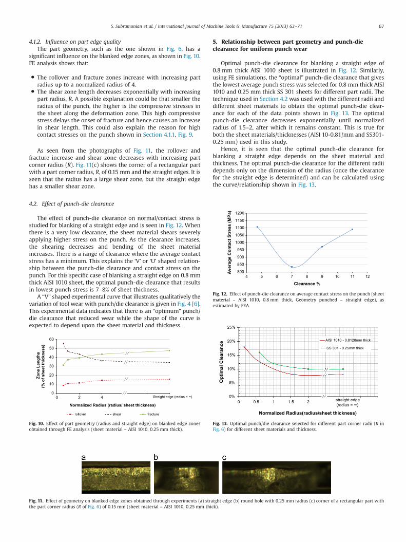
4.1.2. Influence on part edge qualityThe part geometry, such as the one shown in Fig. 6, has a
significant influence on the blanked edge zones, as shown in Fig. 10.FE analysis shows that:
� The rollover and fracture zones increase with increasing partradius up to a normalized radius of 4.
� The shear zone length decreases exponentially with increasingpart radius, R. A possible explanation could be that smaller theradius of the punch, the higher is the compressive stresses inthe sheet along the deformation zone. This high compressivestress delays the onset of fracture and hence causes an increasein shear length. This could also explain the reason for highcontact stresses on the punch shown in Section 4.1.1, Fig. 9.
As seen from the photographs of Fig. 11, the rollover andfracture increase and shear zone decreases with increasing partcorner radius (R). Fig. 11(c) shows the corner of a rectangular partwith a part corner radius, R, of 0.15 mm and the straight edges. It isseen that the radius has a large shear zone, but the straight edgehas a smaller shear zone.
4.2. Effect of punch-die clearance
The effect of punch-die clearance on normal/contact stress isstudied for blanking of a straight edge and is seen in Fig. 12. Whenthere is a very low clearance, the sheet material shears severelyapplying higher stress on the punch. As the clearance increases,the shearing decreases and bending of the sheet materialincreases. There is a range of clearance where the average contactstress has a minimum. This explains the ‘V’ or ‘U’ shaped relation-ship between the punch-die clearance and contact stress on thepunch. For this specific case of blanking a straight edge on 0.8 mmthick AISI 1010 sheet, the optimal punch-die clearance that resultsin lowest punch stress is 7–8% of sheet thickness.
A “V” shaped experimental curve that illustrates qualitatively thevariation of tool wear with punch/die clearance is given in Fig. 4 [6].This experimental data indicates that there is an “optimum” punch/die clearance that reduced wear while the shape of the curve isexpected to depend upon the sheet material and thickness.
5. Relationship between part geometry and punch-dieclearance for uniform punch wear
Optimal punch-die clearance for blanking a straight edge of0.8 mm thick AISI 1010 sheet is illustrated in Fig. 12. Similarly,using FE simulations, the “optimal” punch-die clearance that givesthe lowest average punch stress was selected for 0.8 mm thick AISI1010 and 0.25 mm thick SS 301 sheets for different part radii. Thetechnique used in Section 4.2 was used with the different radii anddifferent sheet materials to obtain the optimal punch-die clear-ance for each of the data points shown in Fig. 13. The optimalpunch-die clearance decreases exponentially until normalizedradius of 1.5–2, after which it remains constant. This is true forboth the sheet materials/thicknesses (AISI 10-0.81/mm and SS301-0.25 mm) used in this study.
Hence, it is seen that the optimal punch-die clearance forblanking a straight edge depends on the sheet material andthickness. The optimal punch-die clearance for the different radiidepends only on the dimension of the radius (once the clearancefor the straight edge is determined) and can be calculated usingthe curve/relationship shown in Fig. 13.
0
10
20
30
40
50
60
0 2 4 6 8 10
Zon
e Le
ngth
s
(% o
f she
et th
ickn
ess)
Normalized Radius (radius/ sheet thickness)
rollover shear fracture
Straight edge (radius = ∞)
Fig. 10. Effect of part geometry (radius and straight edge) on blanked edge zonesobtained through FE analysis (sheet material – AISI 1010, 0.25 mm thick).
800
850
900
950
1000
1050
1100
1150
1200
4 5 6 7 8 9 10 11 12
Ave
rage
Con
tact
Str
ess
(MPa
)
Clearance %
Fig. 12. Effect of punch-die clearance on average contact stress on the punch (sheetmaterial – AISI 1010, 0.8 mm thick, Geometry punched – straight edge), asestimated by FEA.
Fig. 11. Effect of geometry on blanked edge zones obtained through experiments (a) straight edge (b) round hole with 0.25 mm radius (c) corner of a rectangular part withthe part corner radius (R of Fig. 6) of 0.15 mm (sheet material – AISI 1010, 0.25 mm thick).
0%
5%
10%
15%
20%
25%
0 0.5 1 1.5 2
Opt
imal
Cle
aran
ce
Normalized Radius(radius/sheet thickness)
AISI 1010 - 0.8128mm thick
SS 301 - 0.25mm thick
straight edge (radius = ∞)
Fig. 13. Optimal punch/die clearance selected for different part corner radii (R inFig. 6) for different sheet materials and thickness.
S. Subramonian et al. / International Journal of Machine Tools & Manufacture 75 (2013) 63–71 67

6. Effect of geometry dependent punch-die clearanceon tool wear
6.1. Simulation of Högman's [6] experimental results
6.1.1. Experimental setup [6]Högman [6] conducted blanking experiments to determine the
influence of punch-die clearance on punch failure. Two differentradii (0.2 mm and 0.5 mm) are used in the rectangular punch, asshown in Fig. 3. A uniform clearance of 10% is maintained in thecase of 0.2 mm radius while a clearance of �20% is maintainedalong the radius in the case of 0.5 mm radius. The blank used inthis study is 1 mm thick Docol 800DP. The tool material used isVanadis 4 with a hardness of 60 HRC.
6.1.2. Simulation setupFE simulations corresponding to the experimental conditions of
Högman [6] are conducted in this study to obtain the punch stress.The simulated stresses in the punch are correlated to the wear andchipping that occurred in the experiments.
6.1.3. Comparison of experimental and FE results6.1.3.1. Experimental results [6]. The punch which had 0.2 mmradius at the corner of the rectangle (10% punch-die clearance)chipped at 45000 strokes. The punch which had 0.5 mm radius atthe corner of the rectangle (20% punch-die clearance) lasted200000 strokes without chipping. Comparison of the punches atthe end of the experiments is shown in Fig. 14.
6.1.3.2. FEA results. The maximum effective punch stress in the caseof 0.2 mm part/punch radius is 2270 MPa while in case of 0.5 mmradius the corresponding stress is 2095 MPa. This is a reduction ofthe stresses by 8%, while the maximum clearance was increasedfrom 10% to 20%.
6.1.3.3. Correlation of experimental and FEA results. This correlationbetween experiments and simulations, as shown in Table 3, furtherillustrates the relation between stress on the tool and tool wear.
6.2. Effect of variable punch-die clearance upon tool wear
In the present investigation, the concept of geometry dependentvariable punch-die clearance is tested by applying it to a progressivedie used in a production environment. The wear on the punch anddies is compared for the two conditions: (i) using uniform punch-die clearance and (ii) using variable punch-die clearance. Thefollowing methodology is used to implement the geometry depen-dent variable clearance.
(1) The complex shapes of the punch are broken down into simplerfeatures. Key features such as straight edge and different radiiare identified.
(2) The optimal punch-die clearances according to the geometry ofthe simple features are obtained from Fig. 13, which gives the“optimum” punch-die clearance as a function of part cornerradius.
(3) Clearances are ‘blended in’ along the perimeter of the dieinsert to obtain the variable clearance along the perimeter ofthe part.
6.2.1. Experimental parametersIn this study, we considered a progressive production die with
several stations used progressively to blank a nickel coated AISI1010 steel sheet, 0.8 mm thick. The punches and die inserts weremade of powder metallurgy (PM) steel. Punches are coated withTiAlN coating. It was observed that the punch coating wears awayat the corners first before progressing to straight edges as shownin Fig. 15. This observation further indicates that the variableclearance in blanking non-round parts is a good approach toalleviate the issue of non-uniform punch wear.
Based on the punch shapes shown in Fig. 16, four simplifiedgeometries were identified to optimize the clearance using simula-tions. They are (i) straight edge (ii) 0.127 mm radius (corresponding toall corners with ‘sharp’ edges) (iii) 0.5 mm radius (iv) 1.27 mm radius.Based on the graph developed in Section 5 (shown in Fig. 13),clearances were selected as shown in Table 4 for the four geometries.
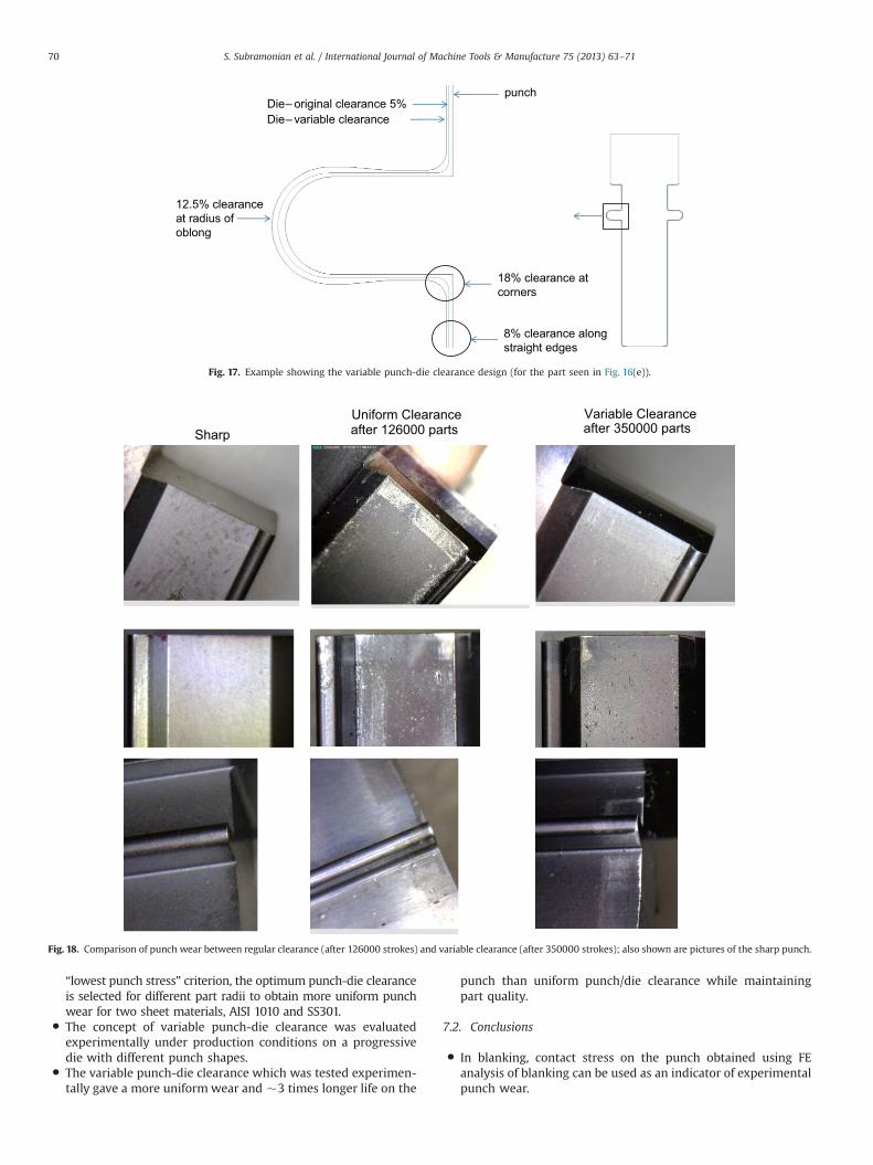
The dies corresponding to all the punches, shown in Fig. 16,were redesigned to implement variable punch-die clearance, Cv.An example is shown in Fig. 17.
6.2.2. Experimental procedureThe following procedure was used to conduct the experiments
and evaluate the results.
(1) Experiments were conducted with two clearance designs(i) uniform punch-die clearance Co and (ii) variable punch-dieclearance Cv under production conditions.
(2) The tests were run until the punch coating showed excessive wearand/or burr height reached the maximum acceptable level of 5 m.
(3) Pictures of the worn punches from both cases were taken tocompare the performance of the two different clearanceconditions.
Displayed region of the punch
Fig. 14. Punches after blanking experiments: (left) Punch with radius 0.2 mm at the corner of the rectangle (10% punch-die clearance) chipped after 40000 strokes (right)Punch with radius 0.5 mm at the corner of the rectangle (20% punch-die clearance) did not chip after 200000 strokes [6].
Table 3Correlation of calculated punch corner stress with punch failure/corner chipping(sheet material – DP 800, thickness – 1 mm).
Punch-dieClearance (%)
Stress at part corner radius(Estimated using FE) (MPa)
Tool Life(Experiment – [5])
10 2270 45,000 strokes20 2095 200,000 strokes
S. Subramonian et al. / International Journal of Machine Tools & Manufacture 75 (2013) 63–7168

6.2.3. Experimental resultsThe uniform punch-die clearance could blank 126,000 parts
before the coating on the punch showed excessive wear and thepart showed excessive burr (greater than 5 m). The punches withvariable clearance were run for 350,000 strokes. The blanked edgeafter 350,000 parts still met all the tolerances specifications for thepart. The burr height also remained below 5 m. The punches didnot see excessive wear on them either. Since it was difficult tomeasure the exact burr height (below 5 m), pictures of wornpunches were used as the parameter to evaluate the effect ofvariable clearance on wear. Fig. 18 shows the wear on threepunches using uniform clearance and variable clearance, alongthe part perimeter. It can be seen that although the variable
clearance punches have about 2.8 times more hits on them thanthe uniform clearance punches, they have more uniform andsignificantly less wear than the uniform clearance punches. Thisresult proves that geometry dependent variable punch-die clear-ance gives a more uniform wear on the punch. The result alsoproves that correlating punch stresses to punch wear is also a goodapproach to select the optimum punch/die clearance.
7. Summary and conclusions
7.1. Summary
� The effect of part geometry (different radii and straight edge)and punch-die clearance on punch stress is obtained fordifferent part radii (R in Fig. 6).
� Blanking of 3 materials, investigated in this study (Fig. 9), showedthat the punch stress decreases exponentially with increasingpunch radius until the radius is about 1.5–2 times sheet thicknessafter which the stress on the punch remains nearly constant.
� There is a range of punch/die clearances where the averagecontact stress on the punch has a minimum. The clearance thatgives the minimum punch stress depends on sheet material,thickness and part radius.
� The optimal punch-die clearance for any given sheet material andthickness varies with the part geometry. Using FE simulations and
Fig. 15. (left) Wear starts around the corners; (right) and then progresses to the straight edges of the punch used in production.
Fig. 16. Punch shapes that are blanked in the progressive die (overall size ranges from (a) �2.5 mm diameter to (e) �25 mm� �8 mm).
Table 4Geometry dependent variable punch-die clearance.
Geometry Original Clearance(Co) (%)
Selected Clearance(Cv) (%)
Straight edge �5 �8Round (1.27 mm radius) �3 �8Radius in oblong (0.5 mmradius)
�5 �12.5
Corner of rectangle (0.127 mmradius)
�5 �18
S. Subramonian et al. / International Journal of Machine Tools & Manufacture 75 (2013) 63–71 69
“lowest punch stress” criterion, the optimum punch-die clearanceis selected for different part radii to obtain more uniform punchwear for two sheet materials, AISI 1010 and SS301.
� The concept of variable punch-die clearance was evaluatedexperimentally under production conditions on a progressivedie with different punch shapes.
� The variable punch-die clearance which was tested experimen-tally gave a more uniform wear and �3 times longer life on the
punch than uniform punch/die clearance while maintainingpart quality.
7.2. Conclusions
� In blanking, contact stress on the punch obtained using FEanalysis of blanking can be used as an indicator of experimentalpunch wear.
punchDie – original clearance 5%Die – variable clearance
18% clearance at corners
8% clearance along straight edges
12.5% clearance at radius of oblong
Fig. 17. Example showing the variable punch-die clearance design (for the part seen in Fig. 16(e)).
SharpUniform Clearance after 126000 parts
Variable Clearance after 350000 parts
Fig. 18. Comparison of punch wear between regular clearance (after 126000 strokes) and variable clearance (after 350000 strokes); also shown are pictures of the sharp punch.
S. Subramonian et al. / International Journal of Machine Tools & Manufacture 75 (2013) 63–7170

� A punch-die clearance variable at the contour of a part gives amore uniform punch stress and hence punch wear, therebyimproving punch life considerably.
� The clearance vs. geometry curve can be used to design variablepunch-die clearance for blanking applications to improvepunch life, as illustrated with an application in production.
Acknowledgments
The authors gratefully acknowledge the support provided byNSF and industry that supported the Center for Precision Formingas well as the support provided by Tyco Electronics Corporation.
References
[1] P. Sartkulvanich, B. Kroenauer, R. Golle, A. Konieczny, T. Altan, Finite Elementanalysis of the effect of blanked edge quality upon stretch flanging of AHSS,CIRP Annals—Manufacturing Technology 59 (2010) 279–282.
[2] R. Wiedenmann, P. Sartkulvanich, T. Altan, Finite element analysis on the effectof sheared edge quality in blanking upon hole expansion of advanced highstrength steel, IDDRG 2009 International Conference, June 2009.
[3] M. Grünbaum, J. Breitling, T. Altan, Influence of high cutting speeds on thequality of blanked parts. Report No. ERC/NSM – S-96-19, Center for PrecisionForming, Columbus, OH, USA, 1996.
[4] T. Bell, Great Designs in Steel presentations, 2005. Available from: ⟨http://www.autosteel.org/en/Great Designs in Steel/Past GDIS Presentations/GDIS2005.aspx⟩, (accessed 16.4.13).
[5] C. Husson, J.P.M. Correia, L. Daridon, S. Ahzi, Finite elements simulations ofthin copper sheets blanking: Study of blanking parameters on sheared edgequality, Journal of Materials Processing Technology 199 (1–3) (2008) 74–83.
[6] B. Högman, Blanking tests of ehs- and uhs- steel sheet. Recent Advances inManufacture & Use of Tools & Dies. October 5–6, 2004, Olofström, Sweden,2004.
[7] A. Goijaerts, L. Govaert, F. Baaijens, Evaluation of Ductile Fracture Models forDifferent materials in Blanking, JMPT 110 (2001) 312–323.
[8] M.G. Cockcroft, D.J. Latham., A Simple Criterion of Fracture for Ductile Metals,National Engineering Laboratory, 1966.
[9] M. Oyane, T. Sato, K. Okimoto, S. Shima, Criteria for ductile fracture and theirapplications, Journal of Mechanical Working Technology 4 (1980) 65–81.
[10] J.R. Rice, D.M. Tracey, On the ductile enlargement of voids in triaxial stressfields, Journal of the Mechanics and Physics of Solids 17 (1969) 201–217.
[11] A.M. Goijaerts, L.E. Govaert, F.P.T. Baaijens, Prediction of ductile fracture inmetal blanking, Transactions-American Society of Mechanical EngineersJournal of Manufacturing Science and Engineering 122 (2000) 476–483.
[12] I. Picas, R. Hernández, D. Casellas, I. Valls, Strategies to increase the toolperformance in punching operations of UHSS, IDDRG 2010 (2010) 325–334.
[13] S. Subramonian, T. Altan, C. Campbell, B. Ciocirlan, Determination of forces inhigh speed blanking using FEM and experiments, Journal of MaterialsProcessing Technology 213 (12) (2013) 2184–2190, ISSN 0924-0136, 10.1016/j.jmatprotec.2013.06.014.
[14] Q. Zhang, M. Arentoft, S. Bruschi, L. Dubar, E. Felder, Measurement of frictionin a cold extrusion operation: study by numerical simulation of four frictiontests, International Journal of Material Forming 1 (2008) 1267–1270.
S. Subramonian et al. / International Journal of Machine Tools & Manufacture 75 (2013) 63–71 71