internet connectivity: fundamental issues
TRANSCRIPT
Chapter 3
Internet Connectivity:
Fundamental Issues
2
Computer Networks
A computer network is the infrastructure necessary for
the transportation of information between two or more
computer systems
3
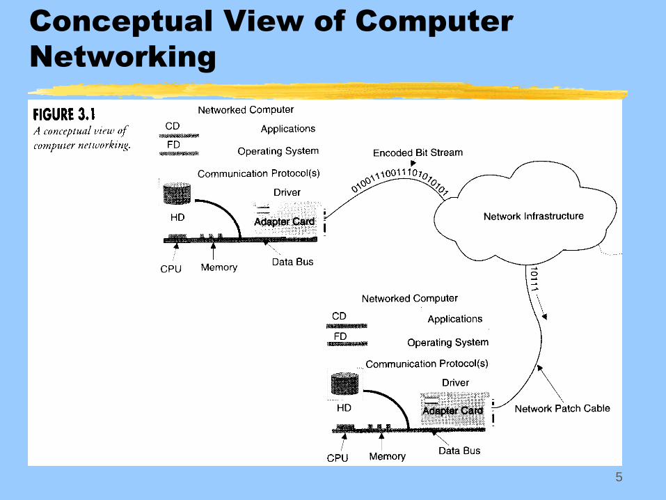
Computer-to-Network Interface
Host systems connect to the network through an
adapter card, often called a network interface card
(NIC)
Adapter cards connect to the host’s internal data bus that
allow it to communicate with the central processing unit
(CPU)
Adapter cards interact with specific software
communication components (communication protocols and
operating system) using a driver
Binding interfaces the communication protocol to the
adapter card driver
4
Computer-to-Network Interface
The host’s operating system allocates resources to its
devices
Device examples: disk drives, NIC, printer
Resource examples: memory, processor time
Operating system is critical to successful communication
Operating system interacts with applications
OSI model (as well as TCP/IP) encompasses all of
these components
Provides structure to communication process
5
Conceptual View of Computer
Networking
6
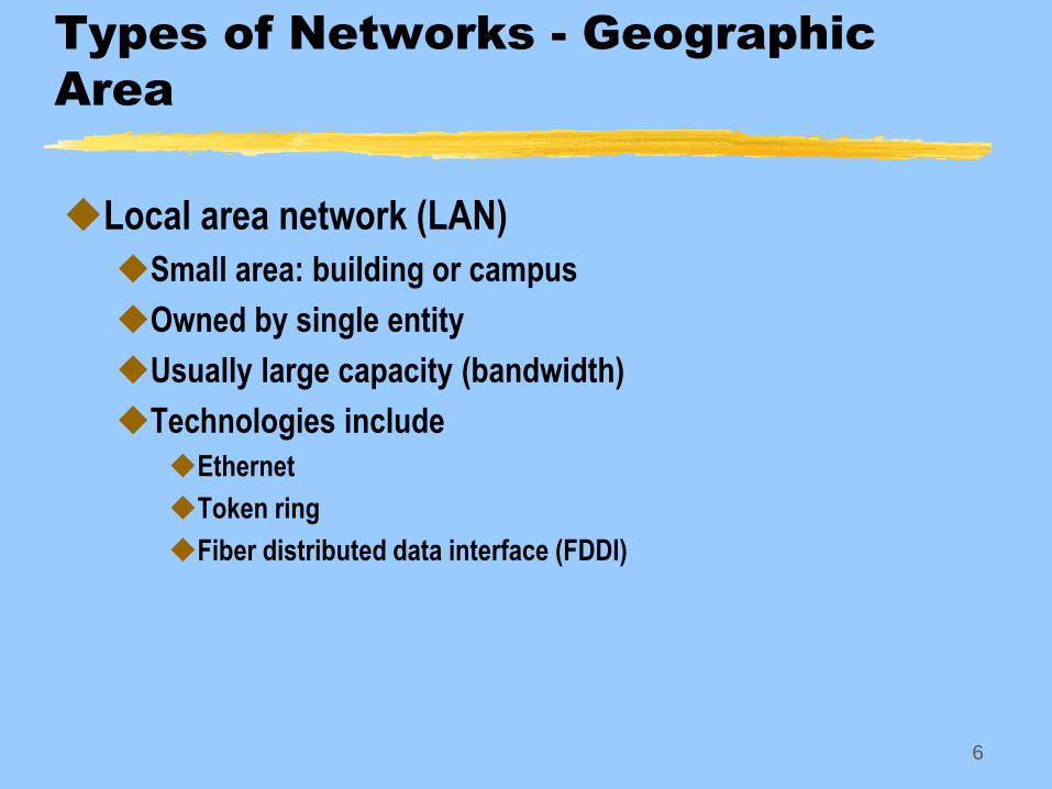
Types of Networks - Geographic
Area
Local area network (LAN)
Small area: building or campus
Owned by single entity
Usually large capacity (bandwidth)
Technologies include
Ethernet
Token ring
Fiber distributed data interface (FDDI)
7
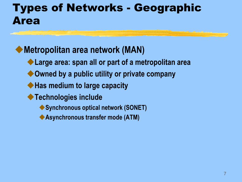
Types of Networks - Geographic
Area
Metropolitan area network (MAN)
Large area: span all or part of a metropolitan area
Owned by a public utility or private company
Has medium to large capacity
Technologies include
Synchronous optical network (SONET)
Asynchronous transfer mode (ATM)
8
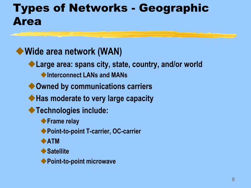
Types of Networks - Geographic
Area
Wide area network (WAN)
Large area: spans city, state, country, and/or world
Interconnect LANs and MANs
Owned by communications carriers
Has moderate to very large capacity
Technologies include:
Frame relay
Point-to-point T-carrier, OC-carrier
ATM
Satellite
Point-to-point microwave
9
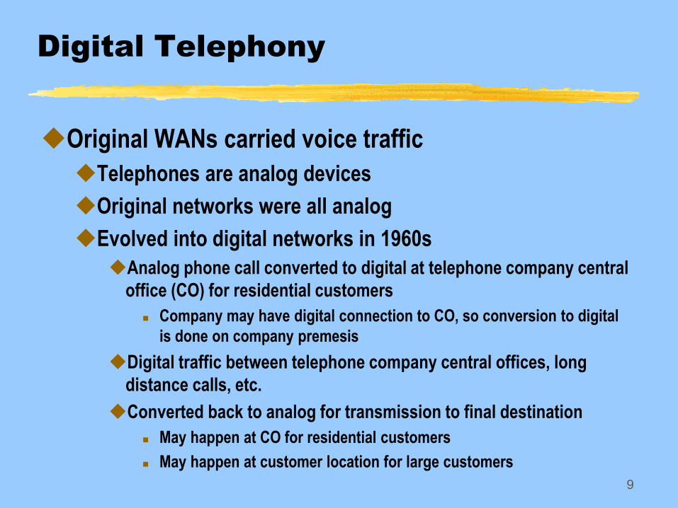
Digital Telephony
Original WANs carried voice traffic
Telephones are analog devices
Original networks were all analog
Evolved into digital networks in 1960s
Analog phone call converted to digital at telephone company central
office (CO) for residential customers
Company may have digital connection to CO, so conversion to digital
is done on company premesis
Digital traffic between telephone company central offices, long
distance calls, etc.
Converted back to analog for transmission to final destination
May happen at CO for residential customers
May happen at customer location for large customers
10
Digitizing Signals
Analog voice signals are converted to digital using
analog-to-digital (A/D) converters
Sample the analog signal
Samples are quantized into digital numbers
11
Digitizing Signals
Analog voice signals are converted to digital using
analog-to-digital (A/D) converters
Sample the analog signal
Samples are quantized and encoded into digital numbers
12
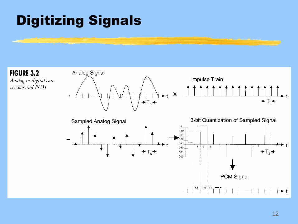
Digitizing Signals
13
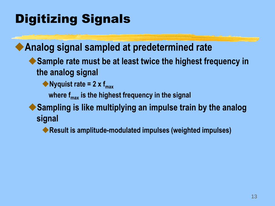
Digitizing Signals
Analog signal sampled at predetermined rate
Sample rate must be at least twice the highest frequency in
the analog signal
Nyquist rate = 2 x fmax
where fmax is the highest frequency in the signal
Sampling is like multiplying an impulse train by the analog
signal
Result is amplitude-modulated impulses (weighted impulses)
14
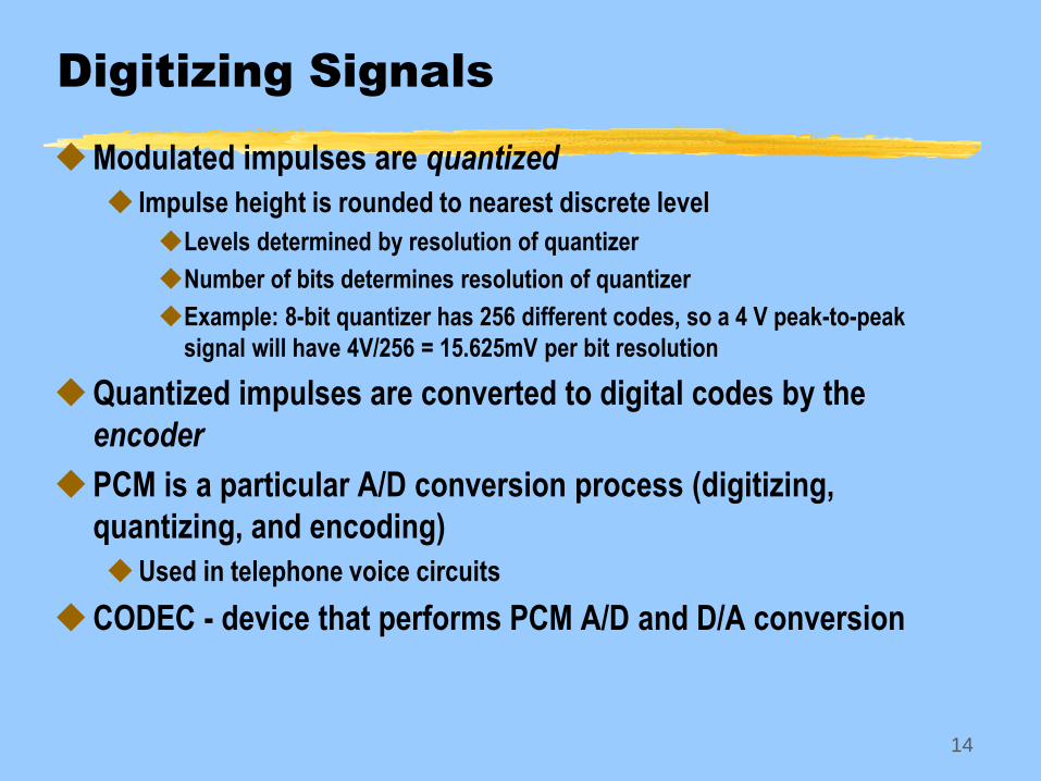
Digitizing Signals
Modulated impulses are quantized
Impulse height is rounded to nearest discrete level
Levels determined by resolution of quantizer
Number of bits determines resolution of quantizer
Example: 8-bit quantizer has 256 different codes, so a 4 V peak-to-peak
signal will have 4V/256 = 15.625mV per bit resolution
Quantized impulses are converted to digital codes by the
encoder
PCM is a particular A/D conversion process (digitizing,
quantizing, and encoding)
Used in telephone voice circuits
CODEC - device that performs PCM A/D and D/A conversion
15
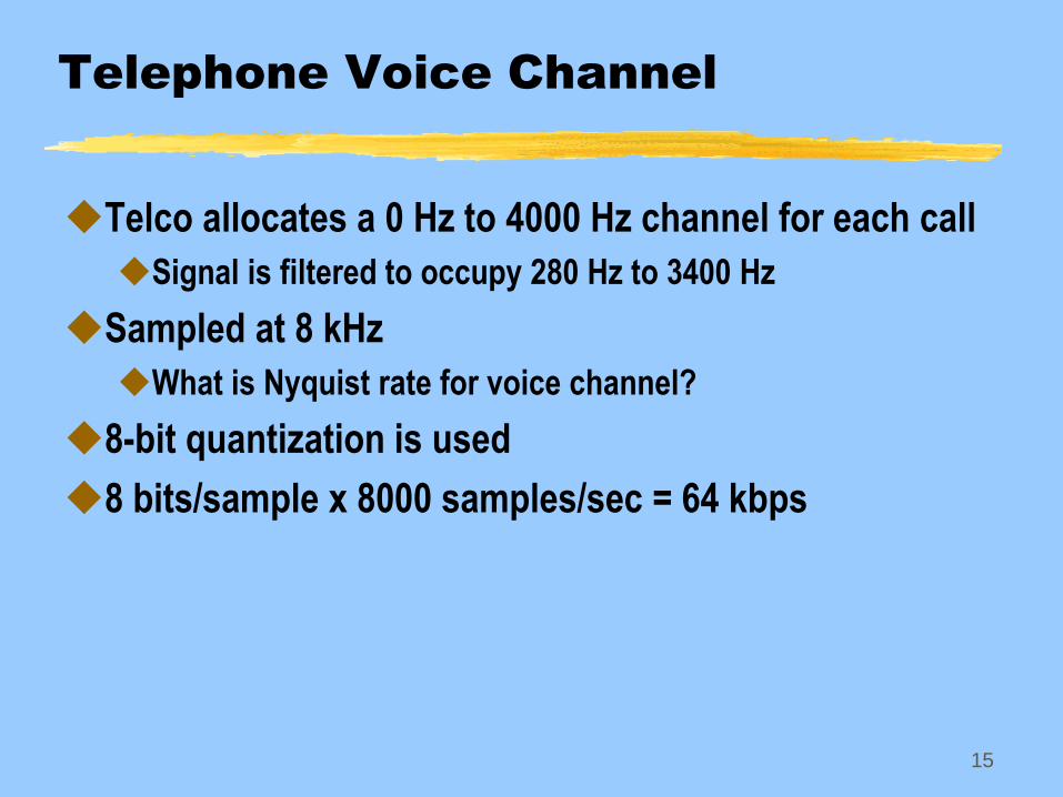
Telephone Voice Channel
Telco allocates a 0 Hz to 4000 Hz channel for each call
Signal is filtered to occupy 280 Hz to 3400 Hz
Sampled at 8 kHz
What is Nyquist rate for voice channel?
8-bit quantization is used
8 bits/sample x 8000 samples/sec = 64 kbps
16
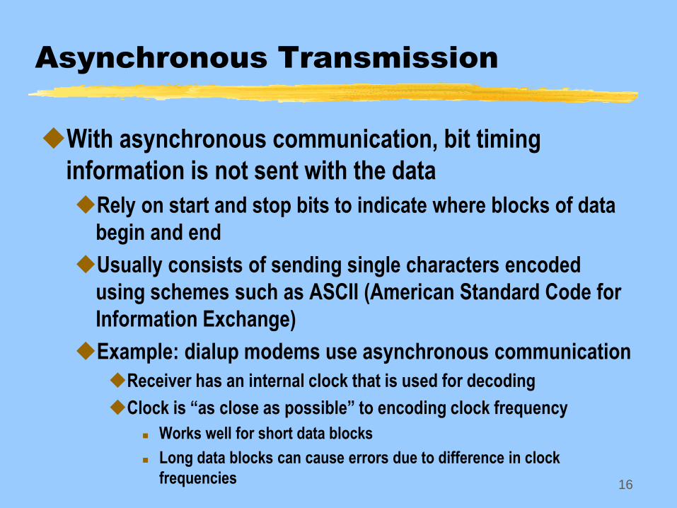
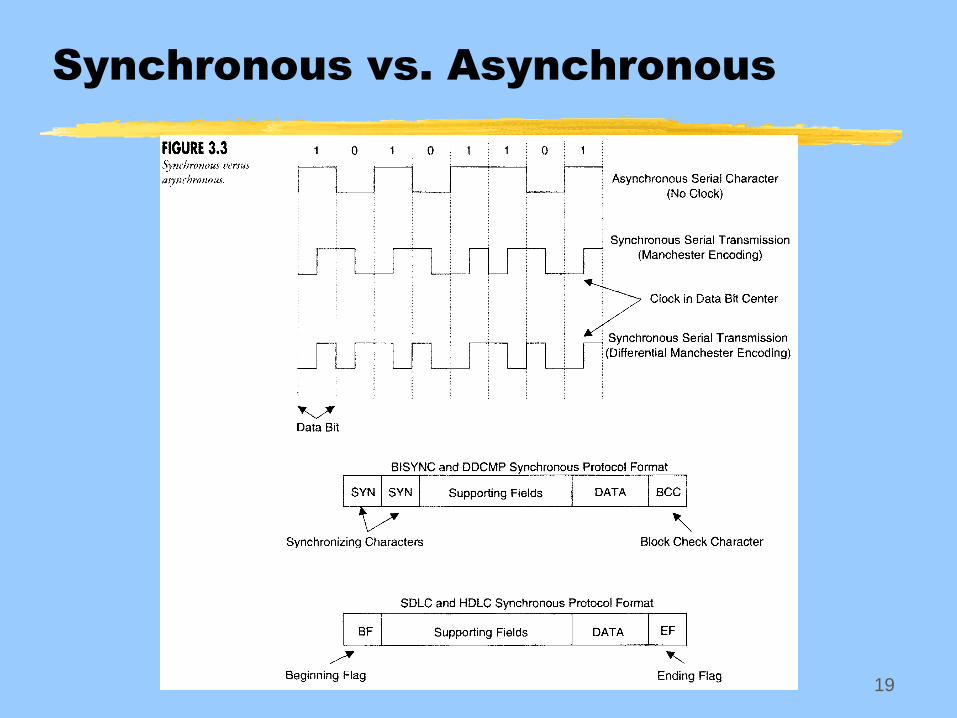
Asynchronous Transmission
With asynchronous communication, bit timing
information is not sent with the data
Rely on start and stop bits to indicate where blocks of data
begin and end
Usually consists of sending single characters encoded
using schemes such as ASCII (American Standard Code for
Information Exchange)
Example: dialup modems use asynchronous communication
Receiver has an internal clock that is used for decoding
Clock is “as close as possible” to encoding clock frequency
Works well for short data blocks
Long data blocks can cause errors due to difference in clock
frequencies
17
Synchronous Transmission
With synchronous communication, bit timing
information is sent with the data
Some schemes use a “preamble” at the beginning of the
frame
Preamble contains synchronizing characters consisting of
alternating 1 and 0 bits that synchronize the receiver’s clock so it is
the same frequency as the transmitter’s
Thus, same clock is used at receiver that was used to encode data at
transmitter
Data entering synchronous networks leave at the same rate
Good for real-time voice
18
Synchronous Transmission
Examples of systems using synchronous communication
Telephone network
Ethernet
Token ring
HDLC - High-Level Data Link Control
19
Synchronous vs. Asynchronous
20
Multiplexing
Multiplexing is the process of selectively combining
the input from several sources onto a single
communication channel
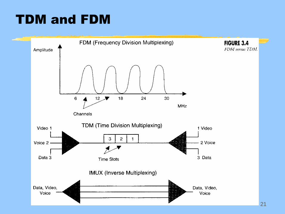
21
TDM and FDM
22
Time Division Multiplexing (TDM)
Multiplexes signal sources into different time slots
Time slots are organized into frames
Example: T1 carrier
Originally designed to carry telephone call traffic
Later adapted to handle data
Each T1 frame has 24 time slots
Each time slot contains a single 8-bit sample from a telephone call
(or data source)
Each frame adds 1 synchronizing bit to the end
23
Statistical Multiplexing
Similar to TDM
Differences
Each channel does not get a fixed, designated time slot
Multiplexer can allocate more than one slot to a single
source when needed
Advantage
Channels get adjustable capacity depending on circuit load
24
Frequency Division Multiplexing (FDM)
Information from signal sources are allocated
channels in a frequency band
Examples
Broadcast TV
Cable TV, cable modem
Wireless telephone
25
Wavelength Division Multiplexing (WDM)
Used for fiber optic transmission
Same as FDM except fiber optic terminology refers to
wavelength instead of frequency
26
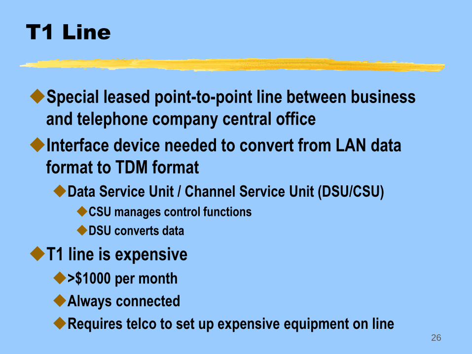
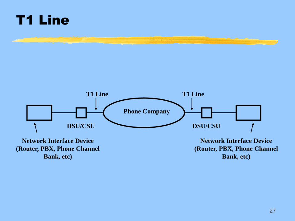
T1 Line
Special leased point-to-point line between business
and telephone company central office
Interface device needed to convert from LAN data
format to TDM format
Data Service Unit / Channel Service Unit (DSU/CSU)
CSU manages control functions
DSU converts data
T1 line is expensive
>$1000 per month
Always connected
Requires telco to set up expensive equipment on line
27
T1 Line
DSU/CSU DSU/CSU
Phone Company
Network Interface Device
(Router, PBX, Phone Channel
Bank, etc)
Network Interface Device
(Router, PBX, Phone Channel
Bank, etc)
T1 Line T1 Line
28
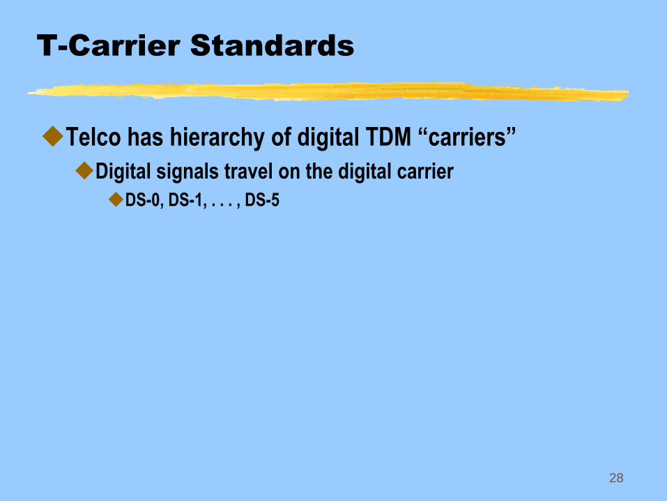
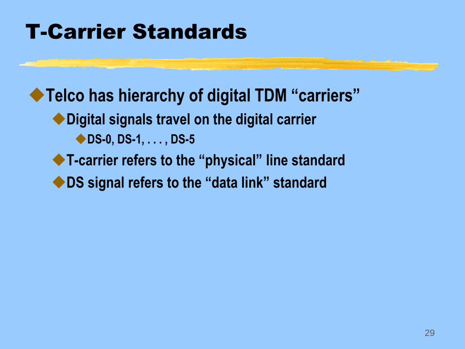
T-Carrier Standards
Telco has hierarchy of digital TDM “carriers”
Digital signals travel on the digital carrier
DS-0, DS-1, . . . , DS-5
29
T-Carrier Standards
Telco has hierarchy of digital TDM “carriers”
Digital signals travel on the digital carrier
DS-0, DS-1, . . . , DS-5
T-carrier refers to the “physical” line standard
DS signal refers to the “data link” standard
30
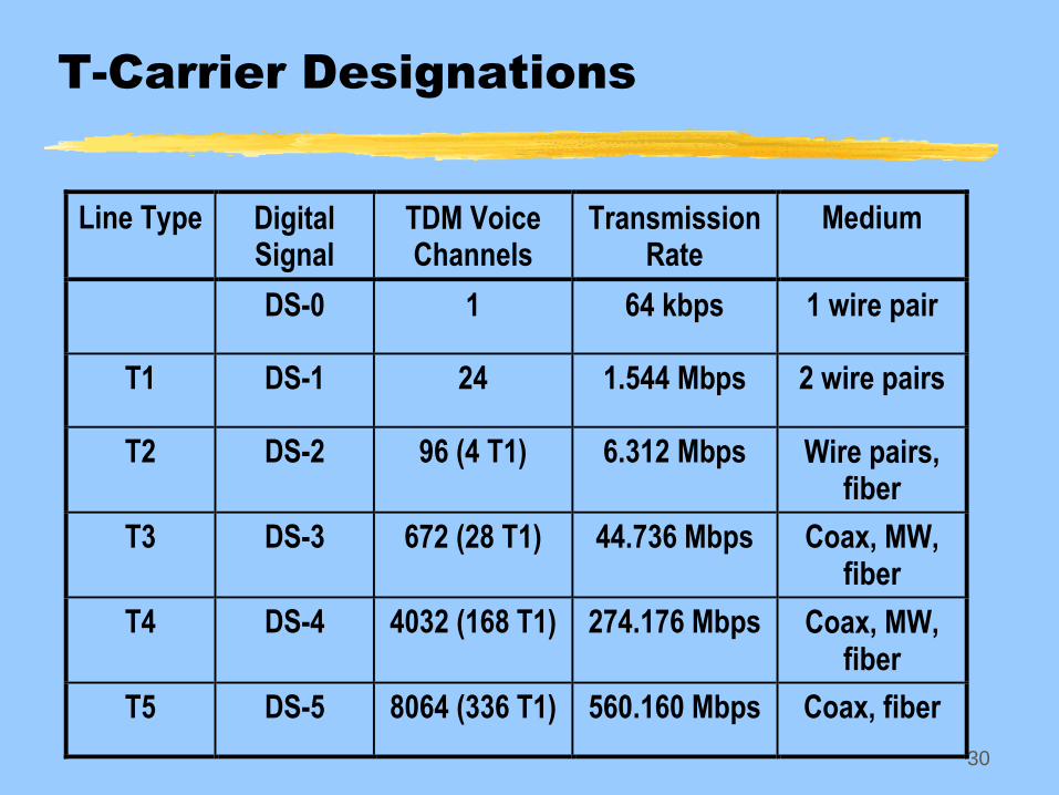
T-Carrier Designations
Line Type DigitalSignal
TDM VoiceChannels
TransmissionRate
Medium
DS-0 1 64 kbps 1 wire pair
T1 DS-1 24 1.544 Mbps 2 wire pairs
T2 DS-2 96 (4 T1) 6.312 Mbps Wire pairs,fiber
T3 DS-3 672 (28 T1) 44.736 Mbps Coax, MW,fiber
T4 DS-4 4032 (168 T1) 274.176 Mbps Coax, MW,fiber
T5 DS-5 8064 (336 T1) 560.160 Mbps Coax, fiber
31
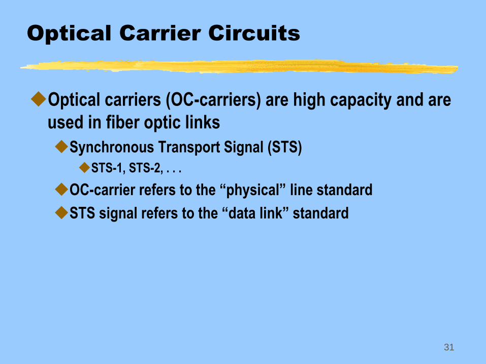
Optical Carrier Circuits
Optical carriers (OC-carriers) are high capacity and are
used in fiber optic links
Synchronous Transport Signal (STS)
STS-1, STS-2, . . .
OC-carrier refers to the “physical” line standard
STS signal refers to the “data link” standard
32
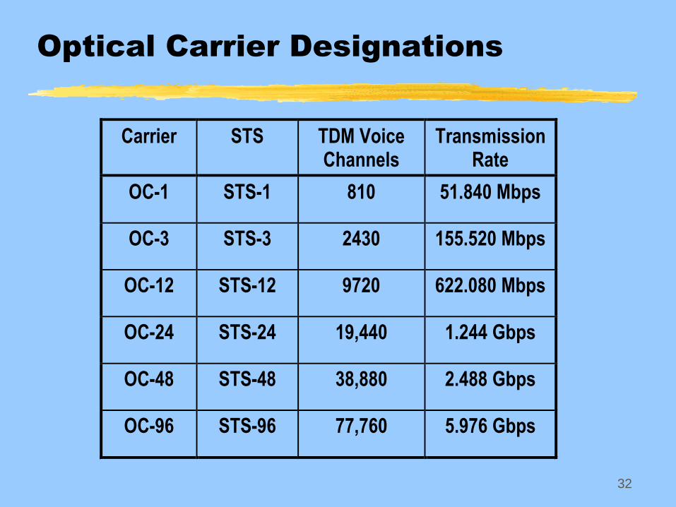
Optical Carrier Designations
Carrier STS TDM Voice Channels
Transmission Rate
OC-1 STS-1 810 51.840 Mbps
OC-3 STS-3 2430 155.520 Mbps
OC-12 STS-12 9720 622.080 Mbps
OC-24 STS-24 19,440 1.244 Gbps
OC-48 STS-48 38,880 2.488 Gbps
OC-96 STS-96 77,760 5.976 Gbps
33
Data Compression
Reduces the number of bits to be transmitted on a link
Compression algorithm used on sending host
Decompression algorithm used on receiving host
Algorithms exploits bit patterns and/or byte patterns in
files
Inserts a fewer number of bits to represent the original bits
in the file
File sizes are reduced prior to transmission
34
Network Topologies
Topology refers to the way network entities are
connected together
Physical topology
How devices are physically connected
Logical topology
How devices logically interact with each other
Example
A logical bus is often connected as a physical star
35
Popular Topologies
Bus
Ring
Star
Tree
Mesh
36
Topologies
37
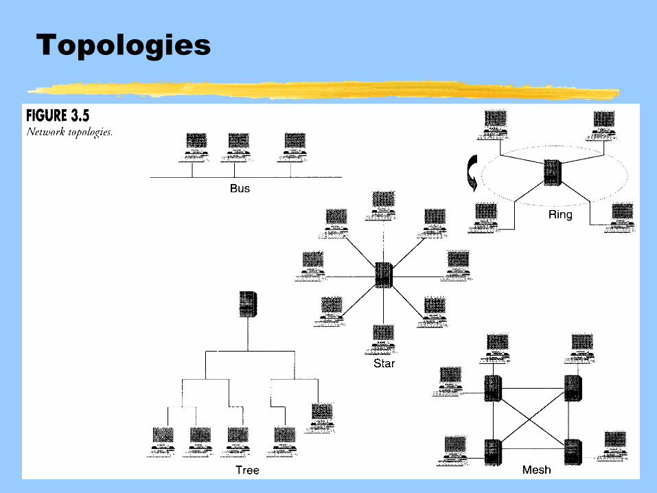
Bus Topology
Shared medium
All nodes receive transmissions from any node on the
bus
Access to transmit on bus controlled by protocol
Attempts to ensure that only one node transmits at a time
Nodes trying to transmit at same time cause a collision
Protocol sorts out who gets to transmit after collision occurs
Example: Ethernet
38
Ring Topology
System of repeaters connected in a loop
All hosts on ring contain a repeater
Repeater reads data frame address
If addressed to that host, repeater passes copy of frame to host’s
upper protocol layers, then passes original frame on to next host
If not addressed to that host, repeater just passes original frame on
to next host
Only one node can transmit and receive at a time
Examples: SONET ring, token-ring LAN
39
Star Topology
Hosts connected to a central node
Forms a star
Hosts communicate with each other through the
central node
Examples: Arcnet, Older mainframe/terminal
arrangements
Special example:
Ethernets are logical busses but can be connected in
physical star
Token-rings are logical rings, but can be connected in
physical star
40
Tree Topology
Hierarchical arrangement of nodes that appears like a
tree
Root of tree is called headend
Example: one-way downstream cable TV channel
delivery
CATV changing to allow some upstream communication
Cable modem
41
Mesh Topology
System of interconnected nodes
Creates redundant paths
Fully-connected mesh is where all nodes are
connected to all other nodes
Creates a very complicated network
Most meshes are not fully-connected
Is the example in Fig. 3-5 fully-connected?
Examples: telephone network, the Internet, Frame
Relay
42
Switching
WANs have used switching techniques to move data
Circuit switching traditionally used by telephone
company
Packet switching used in modern data networks
43
Circuit Switching
Voice and/or data is transported across the network on
a dedicated circuit
Three phases
Connection establishment
Relies on a signaling protocol to set up connection
Example: dialing a phone number initiates the signaling protocol to
set up a voice circuit path
Data transfer
Connection termination
Data move across network in constant bit rate
44
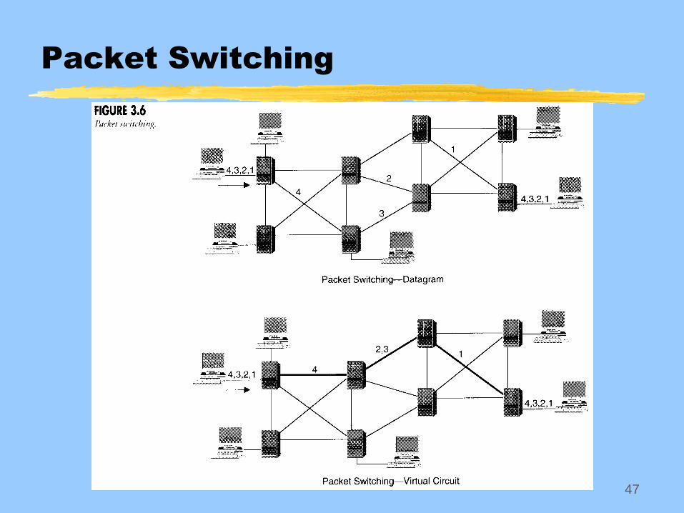
Packet Switching
Data is segmented into packets, each containing
routing information
May just be a destination address
May include a complete route
Routing nodes in networks use packet routing
information to decide which path to send packet
Small delays created at each routing node to process packet
routing information
Data moves across network at a variable bit rate
45
Connectionless Packet Switching
Packets that are part of a single session may follow
different paths to destination
Independent packets known as datagrams
46
Connection-Oriented Packet
Switching
Also known as virtual circuit
Packets follow the same path to destination
Packets sent from source may contain complete list of
intermediate routers (source routing), or
Packets may have a connection identifier number
Intermediate routers read the connection identifier and send the
packet on a pre-determined path
Path determined during connection establishment
47
Packet Switching
48
Connection Oriented Confusion
Is it the same thing when we call TCP a “connection-
oriented” protocol and then talk about connection-
oriented routing?
With respect to TCP, connection-oriented refers to
establishing and maintaining a reliable connection so that all
packets will be delivered between hosts and does not mean
that the IP packets will follow a fixed route
Connection-oriented routing means the packets follow a
fixed route
Similarly, UDP is a connectionless protocol, but this
has nothing to do with the way the packets are routed
49
Matrix Switching
Commonly used in LANs
A switch “matrix” is used where all hosts can be
directly connected to each other by the switch
Can be unicast, multicast, or broadcast (one-to-one, one-to-
many, or one-to-all)
Used in MAC layer of switched Ethernet networks
No longer a shared medium
Hosts not in destination address of MAC frame do not see
the frame!!
50
Multi-Rate Circuit Switching
Refers to moving data to (or from) a lower bit rate path
from (or to) a higher bit rate path
This technique is used to multiplex 28 T1 lines on to a
single T3 line
51
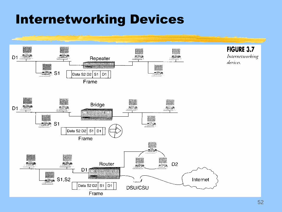
Internetworking Devices
Many different types
Main ones
Repeaters
Bridges
Routers
Gateways
Functions of these devices may be combined in one
52
Internetworking Devices
53
Repeater
Extends the size of a LAN by interconnecting multiple
segments
Data received at input port is copied and re-sent to all
output ports
Operates at OSI layer 1
Can interconnect different types of media like coax and
twisted pair
Cannot interconnect different data-link (layer 2 protocols)
like token-ring and Ethernet
54
Bridge
Expands LAN size by interconnecting segments but
can also segregate data traffic between segments
Bridge “learns” MAC addresses of hosts and which
segment the host is on
Develops a routing table of MAC addresses
Traffic between hosts on same segment is not
transmitted across the bridge to another segment
Traffic from a host on one segment having destination
address of a host on another segment is transmitted
across the bridge
55
Bridge
Operates on layers 1 through 2 of the OSI model
Can detect errors in frames (checksums that don’t match)
and will discard them
What if multiple bridges are used to connect
segments?
Cannot permit a forwarding loop to occur or frames will
continue to circulate the network, eventually overloading it
56
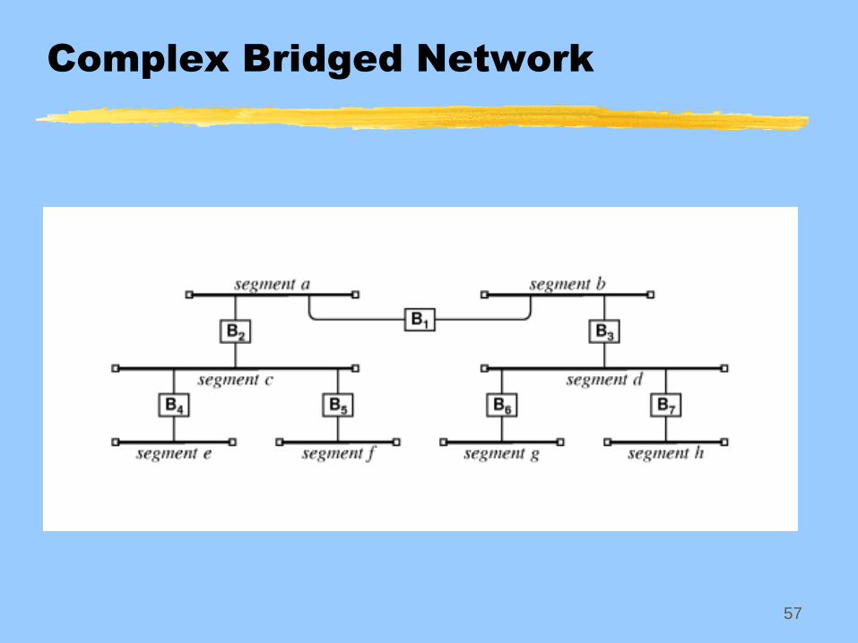
Bridge
Spanning Tree Protocol eliminates loops of bridges
Contained in IEEE 802.1d specification
Bridges communicate with each other and eventually determine that
one of them will not forward frames from one segment to another
Bridges/switches exchange messages with each other using Bridge
Protocol Data Units
Elect a root bridge/switch
Elect a designated bridge/switch for each LAN segment
Remove loops by placing redundant ports in a backup state (path
redundancy)
Result is a “tree” with no connected loops
STP provides path redundancy while eliminating loops
57
Complex Bridged Network
58
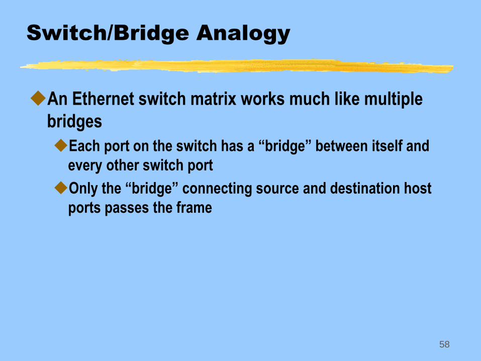
Switch/Bridge Analogy
An Ethernet switch matrix works much like multiple
bridges
Each port on the switch has a “bridge” between itself and
every other switch port
Only the “bridge” connecting source and destination host
ports passes the frame
59
Router
Expands the size of a network (LAN or WAN)
Segregates traffic between network segments based
on internetwork addresses (not MAC)
Interconnects networks that use different MAC
protocols
Router needs the proper interface for each network
Operates on OSI layers 1 through 3
Multiple routers can be used in hierarchical designs
for better network segmentation
60
Router
Can perform many sophisticated functions related to
networking protocols depending on software
Support various internetworking protocols (IPX, IP, etc)
Perform packet filtering on interfaces
Restricts traffic in or out of interface based on criteria such as
source IP address or TCP port
Implement network address translation (NAT)
Establish virtual private networks by using encrypted data
paths
Support different routing protocols (RIP, OSPF, BGP)
Can run firewall software
61
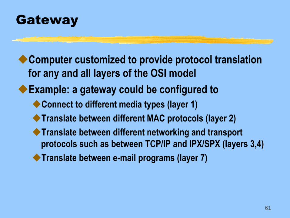
Gateway
Computer customized to provide protocol translation
for any and all layers of the OSI model
Example: a gateway could be configured to
Connect to different media types (layer 1)
Translate between different MAC protocols (layer 2)
Translate between different networking and transport
protocols such as between TCP/IP and IPX/SPX (layers 3,4)
Translate between e-mail programs (layer 7)
62
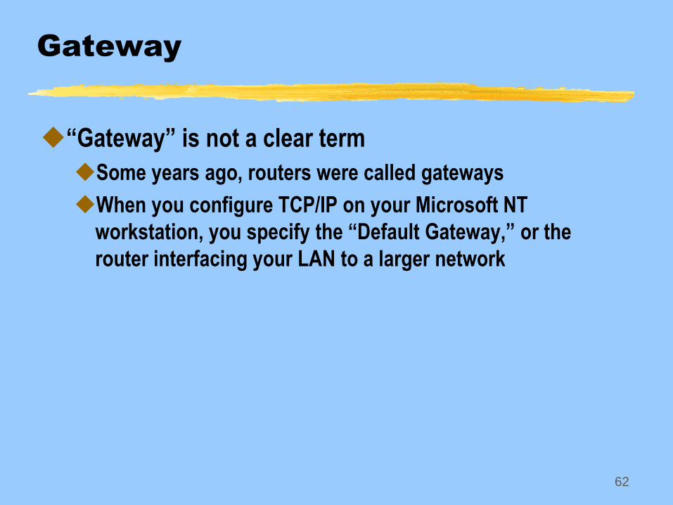
Gateway
“Gateway” is not a clear term
Some years ago, routers were called gateways
When you configure TCP/IP on your Microsoft NT
workstation, you specify the “Default Gateway,” or the
router interfacing your LAN to a larger network
63
Bandwidth and Capacity
In computer networking arena, the term bandwidth is
frequently misused
The bandwidth of a communication system is the width of a
band of frequencies assigned to the system
Can also mean the maximum range of frequencies that the system
can support
Example, telephone voice channel bandwidth is 0-4kHz, with the
actual signal filtered to fall within 280Hz to 3400 Hz ( 3,120 Hz signal
bandwidth)
Capacity is the data rate that can be supported by the
communication channel
Measured in bits per second
64
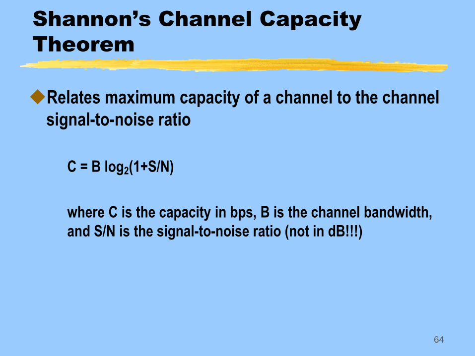
Shannon’s Channel Capacity
Theorem
Relates maximum capacity of a channel to the channel
signal-to-noise ratio
C = B log2(1+S/N)
where C is the capacity in bps, B is the channel bandwidth,
and S/N is the signal-to-noise ratio (not in dB!!!)

65
Shannon’s Channel Capacity
Theorem
Relates maximum capacity of a channel to the channel
signal-to-noise ratio
C = B log2(1+S/N)
where C is the capacity in bps, B is the channel bandwidth,
and S/N is the signal-to-noise ratio (not in dB!!!)
66
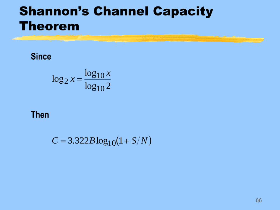
Shannon’s Channel Capacity
Theorem
Since
Then
2log
loglog
10
102
xx
NSBC 1log322.3 10
67
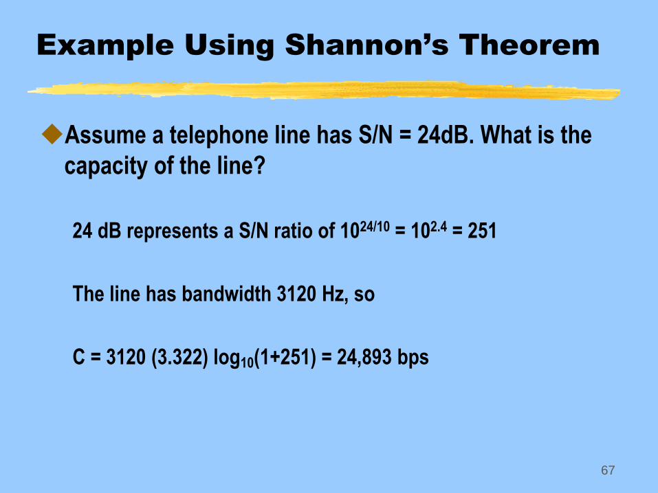
Example Using Shannon’s Theorem
Assume a telephone line has S/N = 24dB. What is the
capacity of the line?
24 dB represents a S/N ratio of 1024/10 = 102.4 = 251
The line has bandwidth 3120 Hz, so
C = 3120 (3.322) log10(1+251) = 24,893 bps
68
Effect of Channel Capacity
Service time
The time it takes for a file of a given size to be transmitted
across a link.
69
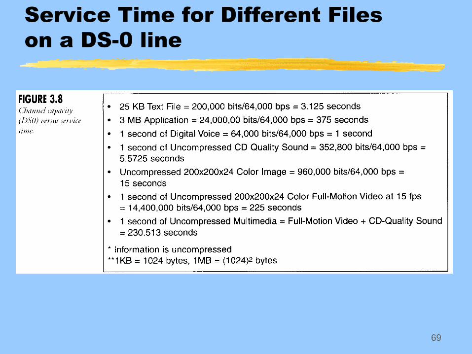
Service Time for Different Files
on a DS-0 line
70
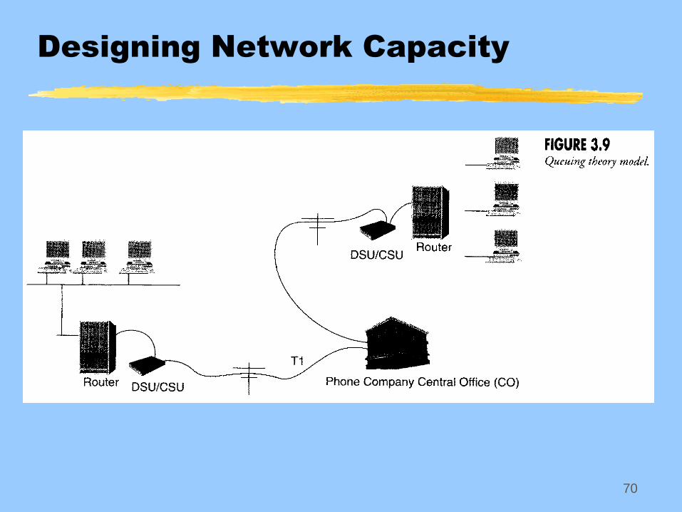
Designing Network Capacity
71
Designing Network Capacity
Queuing theory is used to determine if the capacity of
a communication channel is sufficient for a given
network design
Example
Assume two Ethernet bus networks are connected with a T1
line
Assume a 1000-byte frame traverses the T1 line
Assume that one Ethernet sends 50 frames/sec to its router,
to be sent across the T1 line to the second Ethernet
72
Designing Network Capacity
The T1 line operates at 1.544 Mbps, with 8000 bps allocated
for timing bits
Thus T1 line capacity is 1.536 Mbps of data
The 1000-bit frame takes
The number of frames per second on the T1 line is
sec102.510536.1
bytebits8bytes1000 361
t
secframes192framesec102.5
1
3
f
73
Designing Network Capacity
Now if one Ethernet is delivering 50 frames to its router and
the router sends them across the T1 line to the second
Ethernet, then the utilization of the T1 line is
Thus, the T1 line is idle 74% of the time and can easily
handle the traffic load
%26or,26.0192
50utilP
74
Online Service Provider vs.
Internet Service Provider
Online Service Provider
Access the Internet indirectly via the service provider’s
computers which operate as a bulletin board service
Proprietary user interface provides customer with all
standard Internet services, such as e-mail and web pages
Example: America Online (AOL)
75
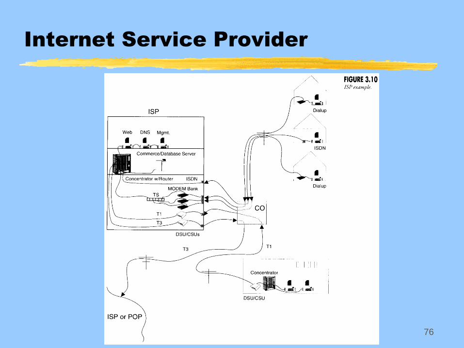
Online Service Provider vs.
Internet Service Provider
Internet Service Provider (ISP)
Provide direct access to the Internet using TCP/IP
Customer’s computer becomes a remote node of the ISP’s
network
ISP assigns the customer an IP address using DHCP
Provides DNS service, web services, e-commerce services
Offer a number of different connectivity options
Dial-up modems
Frame Relay, Integrated Services Digital Network (ISDN), T1, etc.
Customer connects to ISP through telephone company central office
(CO)
ISP connects to major internet connectivity site, or POP
(Point-of-Presence) using high-capacity TDM line like T3
76
Internet Service Provider