intesisbox mh-rc-mbs-1 english user manual · • direct connection to modbus rtu (eia-485)...
TRANSCRIPT

IntesisBox® MH-RC-MBS-1 v.0.14
Modbus RTU (EIA-485) Interface for Mitsubishi Heavy Industries air
conditioners.
User Manual Issue Date: 12/2017
r6.2 EN
Order Codes:
MH-RC-MBS-1: Modbus RTU Interface for Mitsubishi Heavy Industries air conditioners

MH-RC-MBS-1 User’s Manual r6.2 EN
© Intesis Software S.L.U. - All rights reserved This information is subject to change without notice
IntesisBox® is a registered trademark of Intesis Software SLU
URL EmailPhone
http://www.intesisbox.com [email protected] +34 938047134
2/23
© Intesis Software S.L.U. 2017. All Rights Reserved.
Information in this document is subject to change without notice. No part of this publication
may be reproduced, stored in a retrieval system or transmitted in any form or any means
electronic or mechanical, including photocopying and recording for any purpose other than the
purchaser’s personal use without the written permission of Intesis Software S.L.U.
Intesis Software S.L.U. Milà i Fontanals, 1 bis 08700 Igualada Spain TRADEMARKS
All trademarks and tradenames used in this document are acknowledged to be the copyright of
their respective holders.

MH-RC-MBS-1 User’s Manual r6.2 EN
© Intesis Software S.L.U. - All rights reserved This information is subject to change without notice
IntesisBox® is a registered trademark of Intesis Software SLU
URL EmailPhone
http://www.intesisbox.com [email protected] +34 938047134
3/23
INDEX
1. Presentation .......................................................................................................... 4
2. Connection ............................................................................................................ 5
2.1 Connect to the AC indoor unit ............................................................................... 5
2.2 Connection to the EIA-485 bus ............................................................................. 6
3. Quick Start Guide ................................................................................................... 6
4. Modbus Interface Specification ................................................................................ 7
4.1 Modbus physical layer.......................................................................................... 7
4.2 Modbus Registers ................................................................................................ 7
4.2.1 Control and status registers ........................................................................... 7
4.2.2 Configuration Registers................................................................................ 10
4.2.3 Considerations on Temperature Registers ...................................................... 11
4.2.4 Special behavior – Center/Remote ................................................................ 13
4.3 DIP-switch Configuration Interface ...................................................................... 15
4.4 Implemented Functions ..................................................................................... 18
4.5 Device LED indicator ......................................................................................... 18
4.6 EIA-485 bus. Termination resistors and Fail Safe Biasing mechanism ...................... 19
5. Mechanical and electrical features .......................................................................... 20
6. List of supported AC Unit Types. ............................................................................ 21
7. Error Codes ......................................................................................................... 22

MH-RC-MBS-1 User’s Manual r6.2 EN
© Intesis Software S.L.U. - All rights reserved This information is subject to change without notice
IntesisBox® is a registered trademark of Intesis Software SLU
URL EmailPhone
http://www.intesisbox.com [email protected] +34 938047134
4/23
1. Presentation
The MH-RC-MBS-1 interfaces allow a complete and natural
integration of Mitsubishi Heavy Industries air conditioners
into Modbus RTU (EIA-485) networks.
Reduced dimensions. 93 x 53 x 58 mm
3.7” x 2.1” x 2.3”
Quick and easy installation. Mountable on DIN rail, wall, or even inside the indoor unit of AC.
• External power not required.
• Direct connection to Modbus RTU (EIA-485) networks. Up to 63 MH-RC-MBS-1 devices can
be connected in the same network. MH-RC-MBS-1 is a Modbus slave device.
• Direct connection to the AC indoor unit. Up to 16 AC indoor units can be connected to MH-
RC-MBS-1, controlling them as one (not individually).
• Configuration from both on-board DIP-switches and Modbus RTU.
• Total Control and Supervision.
• Real states of the AC unit's internal variables.
• Allows simultaneous use of the AC’s remote controls and Modbus RTU.
* Up to 63 IntesisBox devices can be installed in the same Modbus RTU bus. However, depending on the configured speed, the
installation of Modbus Repeaters may be required
• SCADA
• PLC
• DDC
• BMS
• HMI
• Controller
• etc
Up to 63
AC indoor
units*
Modbus RTU EIA-485 network
Modbus RTU Master device
MH-RC-MBS-1
MH-RC-MBS-1
MH-RC-MBS-1

MH-RC-MBS-1 User’s Manual r6.2 EN
© Intesis Software S.L.U. - All rights reserved This information is subject to change without notice
IntesisBox® is a registered trademark of Intesis Software SLU
URL EmailPhone
http://www.intesisbox.com [email protected] +34 938047134
5/23
2. Connection
The interface comes with a plug-in terminal block of 2 poles to establish direct connection with
the AC indoor unit. It comes as well with a plug-in terminal block of 2 poles to establish direct
connection with the Modbus RTU EIA-485 network.
2.1 Connect to the AC indoor unit
The MH-RC-MBS-1 connects directly to the Mitsubishi Heavy Industries XY Bus, which is not
provided within the interface. Depending on which controllers are available, the recommended
connection’ methods are the following ones (details in Figure 2. 1):
• Wired remote controller available. Connect the gateway as Slave in parallel with the
wired remote controllers (Controller acts as Master).
• No remote controller available Connect the gateway directly to the XY bus of the
indoor unit as Master when there is no Mitsubishi Heavy Industries Remote Controller.
Maximum XY bus length is 600 m / 1,968.5 ft. The bus has no polarity sensitivity.
IntesisBox® MH-RC-MBS-1
MODBUS RTU EIA-485
Bus
EIA485 A+ B-
X Y AC Unit
AC Indoor Unit
Max. 600 m / 1,968.5 ft
Connection to XY bus. Two wire cable.
Y X
AC Indoor Unit
IntesisBox® MH-RC-MBS-1
MODBUS RTU
EIA-485
Bus
EIA485 A+ B-
X Y
AC Unit
53 mm / 2.1”
For wall mounting extract the upper and down staples until you hear the "click".
X Y
MHI
Max. 600 m / 1,968.5 ft
Remote Controller
Y X
90 mm / 3.5”
Connection to XY bus. Two wire cable.
53 mm / 2.1”
90 mm / 3.5”
Figure 2. 1 MH-RC-MBS-1 connection diagram
Internal electronic control board
Internal electronic control board

MH-RC-MBS-1 User’s Manual r6.2 EN
© Intesis Software S.L.U. - All rights reserved This information is subject to change without notice
IntesisBox® is a registered trademark of Intesis Software SLU
URL EmailPhone
http://www.intesisbox.com [email protected] +34 938047134
6/23
2.2 Connection to the EIA-485 bus
Connect the EIA-485 bus wires to the plug-in terminal block of MH-RC-MBS-1 and keep the
polarity on this connection (A+ and B-). Make sure that the maximum distance to the bus is
1,200 meters (3,937 ft). Loop or star typologies are not allowed in the case of the EIA-485 bus.
A terminator resistor of 120Ω must be present at each end of the bus to avoid signal reflections.
The bus needs a fail-safe biasing mechanism (see section 4.6 for more details).
3. Quick Start Guide
1. Disconnect the air conditioning from the Mains Power.
2. Attach the interface next to the AC indoor unit (wall mounting) following the instructions
of the diagram below or install it inside the AC indoor unit (respect the safety
instructions given).
3. Connect the XY bus between the interface and the AC indoor unit following the
instructions of the diagram. Screw each bare cable end in the corresponding XY
terminals of each device.
4. Connect the EIA-485 bus to the connector EIA485 of the interface.
5. Close the AC indoor unit.
6. Check the DIP-Switch configuration of the IntesisBox interface and make sure it matches
the current installation’s parameters.
By default, the interface is set to:
Modbus Slave Address 1
Modbus baud rate 9600 bps
These parameters can be modified from SW4 and SW3 DIP-Switches.
All other switch positions are set at low level (Off position ) by default.
NOTE: All changes on the DIP-Switch configuration require a system power cycle to be
applied.
7. Connect the AC system to Mains Power.
IMPORTANT: The IntesisBox interface requires to be connected to the AC unit
(powered) to start communicating.
ON ON
SW3 SW4
MH-RC-MBS-1 User’s Manual r6.2 EN
© Intesis Software S.L.U. - All rights reserved This information is subject to change without notice
IntesisBox® is a registered trademark of Intesis Software SLU
URL EmailPhone
http://www.intesisbox.com [email protected] +34 938047134
7/23
4. Modbus Interface Specification
4.1 Modbus physical layer
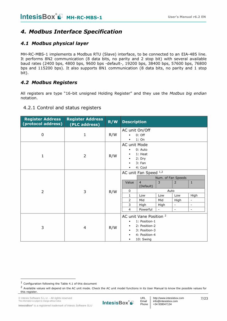
MH-RC-MBS-1 implements a Modbus RTU (Slave) interface, to be connected to an EIA-485 line.
It performs 8N2 communication (8 data bits, no parity and 2 stop bit) with several available
baud rates (2400 bps, 4800 bps, 9600 bps -default-, 19200 bps, 38400 bps, 57600 bps, 76800
bps and 115200 bps). It also supports 8N1 communication (8 data bits, no parity and 1 stop
bit).
4.2 Modbus Registers
All registers are type “16-bit unsigned Holding Register” and they use the Modbus big endian
notation.
4.2.1 Control and status registers
Register Address
(protocol address)
Register Address
(PLC address) R/W Description
0 1 R/W AC unit On/Off
0: Off
1: On
1 2 R/W
AC unit Mode
0: Auto
1: Heat
2: Dry
3: Fan
4: Cool
2 3 R/W
AC unit Fan Speed 1,2
Num. of Fan Speeds
Value 4
(Default) 3 2 1
0 Auto
1 Low Low Low High
2 Mid Mid High -
3 High High - -
4 Powerful - - -
3 4 R/W
AC unit Vane Position 2
1: Position-1
2: Position-2
3: Position-3
4: Position-4
10: Swing
1 Configuration following the Table 4.1 of this document
2 Available values will depend on the AC unit mode. Check the AC unit model functions in its User Manual to know the possible values for
this register.

MH-RC-MBS-1 User’s Manual r6.2 EN
© Intesis Software S.L.U. - All rights reserved This information is subject to change without notice
IntesisBox® is a registered trademark of Intesis Software SLU
URL EmailPhone
http://www.intesisbox.com [email protected] +34 938047134
8/23
Register Address
(protocol address)
Register Address
(PLC address) R/W Description
4 5 R/W
AC unit Temperature Setpoint 2,3,4
-32768 (Initialization value)
ALL MODES (EXCEPT HEAT)
18..30ºC (ºC/x10ºC)
64..86ºF
HEAT
16..30ºC (ºC/x10ºC)
61..61ºF
5 6 R
AC unit Temperature reference 2,3,4
-32768 (Initialization value)
10..38ºC (ºC/x10ºC)
50..100ºF
6 7 R/W Window Contact
0: Closed (Default)
1: Open
7 8 R/W MH-RC-MBS-1 Disablement 5
0: MH-RC-MBS-1 enabled (Default)
1: MH-RC-MBS-1 disabled
8 9 R/W AC Remote Control Disablement 5
0: Remote Control enabled (Default)
1: Remote Control disabled
9 10 R/W AC unit Operation Time
0..65535 (hours). Counts the time the AC
unit is in “On” state.
10 11 R AC unit Alarm Status
0: No alarm condition
1: Alarm condition
11 12 R
Error Code 6
0: No active error
65532 (-4): Initialization process (around
2min) before normal operation starts. This error appears in case that MH-RC-MBS-1 is set as Master.
65535 (-1): Error in the communication of MH-RC-MBS-1 or Remote Controller with the AC unit.
Any other error present, see the table at the end of this document.
22 23 R/W
Indoor unit´s ambient temperature from
external sensor (at Modbus side) 2,3,4,7 -32768: (Initialization value). No
temperature is being provided from an input sensor. There’s no input sensor.
Any other: (ºC/x10ºC/ºF)
3 Magnitude for this register can be adjusted to Celsius x 1ºC, Celsius x 10ºC (default) or Fahrenheit. See section 4.2.3 for more
information. 4 It is not possible turn to x10 the value shown in Fahrenheit. 5 This value is stored in non-volatile memory
6 See section 7 for possible error codes and their explanation 7 See section 4.2.3 for more information

MH-RC-MBS-1 User’s Manual r6.2 EN
© Intesis Software S.L.U. - All rights reserved This information is subject to change without notice
IntesisBox® is a registered trademark of Intesis Software SLU
URL EmailPhone
http://www.intesisbox.com [email protected] +34 938047134
9/23
Register Address
(protocol address)
Register Address
(PLC address) R/W Description
23 24 R
AC Real temperature setpoint 2,3,4,7 When the mechanism for “Virtual
temperature” is not being applied, the value will be the one in the register 5 (PLC addressing).
16..31ºC (ºC/x10ºC)
60..90ºF
24 25 R Current AC max setpoint 2,3,4
-32768 (Initialization value)
Ranges are specific from Manufacturer
25 26 R Current AC min setpoint 2,3,4
-32768 (Initialization value)
Ranges are specific from Manufacturer
31 32 R Status (feedback)
0: Not active (Default value)
1: Active (A window is open)
46 47 R
Center/Remote 8
0: Remocon unlock (Center/Remote) 1: Remocon lock On/Off (Center) 2: Remocon lock All (Center) 3: Remocon Only (Remote)
55 56 R/W Under voltage counter 5
0..300(hours)
60 61 R
Outdoor Intake temperature 2,3,4
-32768d: (Initialization value)
No temperature’s value is being provided outdoor. No virtual temperature is applied.
Any other: (ºC/x10ºC/ºF)
65 66 R
Input reference temperature 2,3,4 -32768: (Initialization value). No
temperature’s value is being provided from an external sensor. No virtual temperature is applied.
Any other: (ºC/x10ºC/ºF)
66 67 R Return Path temperature 2,3,4
-32768 (Initialization value)
Any: (ºC/x10ºC/ºF)
97 98 R/W Block Periodic Sendings 5,9,10
0: Non-blocked (Default value)
1: Blocked
98 99 R/W Master/Slave (gateway)
0: Slave
1: Master
8 See section 4.2.4 for more information 9 If the register is configured as “0:Non-blocked”, all commands received from Modbus will be sent to the AC system. If “1: Blocked”,
commands from Modbus will only be sent to the AC system if they differ from the previous value. 10 This register applies to firmware version 0.14 onwards

MH-RC-MBS-1 User’s Manual r6.2 EN
© Intesis Software S.L.U. - All rights reserved This information is subject to change without notice
IntesisBox® is a registered trademark of Intesis Software SLU
URL EmailPhone
http://www.intesisbox.com [email protected] +34 938047134
10/23
4.2.2 Configuration Registers
Register Address
(protocol address)
Register Address
(PLC address) R/W Description
13 14 R/W “Open Window” switch-off timeout 11
0..30 (minutes)
Factory setting: 30 (minutes)
14 15 R
Modbus RTU baud-rate 2400bps
4800bps
9600bps (Default)
19200bps
38400bps
57600bps
76800bps
115200bps
15 16 R Modbus Slave Address
1..63
21 22 R Max number of fan speeds
45 46 W Error reset
1: Reset
48 49 R Switch value
49 50 R Device ID: 0x0F00
50 51 R Software version
81 82 R Error address
Provides the indoor unit number which is
providing error
99 100 W Reset
1: Reset
While the initialization is ongoing, some Modbus registers will indicate an undetermined value.
Once the normal operation starts, they will acquire its corresponding value. It is important to
keep in mind that any change done during the initialization process will not have effect until it
has been finished.
11 Once window contact is open, a count-down to switch off the AC Unit will start from this configured value.

MH-RC-MBS-1 User’s Manual r6.2 EN
© Intesis Software S.L.U. - All rights reserved This information is subject to change without notice
IntesisBox® is a registered trademark of Intesis Software SLU
URL EmailPhone
http://www.intesisbox.com [email protected] +34 938047134
11/23
4.2.3 Considerations on Temperature Registers
• AC unit temperature setpoint (R/W)
(register 4 – in Protocol address / register 5 – in PLC address):
This is the adjustable temperature setpoint value that must be required by the user. This
register can be read (Modbus function 3 or 4) or written (Modbus functions 6 or 16). A
remote controller connected to the Mitsubishi Heavy Industries indoor unit will report the
same temperature setpoint value as this register, but only will happen when no AC
unit´s external reference is provided from MH-RC-MBS-1 (see detail for register 22/23
below).
• AC unit temperature reference (R)
(register 5 – in Protocol address / register 6 – in PLC address):
This register reports the temperature that is currently used by the Mitsubishi Heavy
Industries indoor unit as the reference of its own control loop. Depending on the
configuration of the indoor unit, this value can be the temperature reported by the
sensor on the return path of the Mitsubishi Heavy Industries indoor unit or the sensor of
its remote controller. It is a read-only register (Modbus functions 3 or 4).
• AC unit external temperature reference (Modbus) (R/W)
(register 22 – in Protocol address / register 23 – in PLC address):
This register allows us to provide an external temperature’s sensor from the Modbus
side. Mitsubishi Heavy Industries indoor unit does not allow on devices like MH-RC-MBS-
1 to provide directly temperature to be used as a reference of the control loop of the AC
indoor unit. In order to overcome this limitation and enable the usage of an external
temperature sensor (i.e.from Modbus side), MH-RC-MBS-1 applies the following
mechanism (only if “external temperature’s reference” is being used):
o After a couple of values have been entered in the “AC unit external temperature’s
reference” (register 22/23) and “AC unit temperature set point” (register 4/5),
MH-RC-MBS-1 is going to estimate the temperature chosen implied (e.g. if a
“temperature setpoint (register 4/5)” of 22ºC, and an “external temperature
reference (register 22/23)” of 20ºC are entered, MH-RC-MBS-1 will assume that
the user is demanding a +2ºC increase in temperature).
o By knowing at any time the ambient temperature currently used by the indoor
unit to control its own operation (register 5/6), MH-RC-MBS-1 can calculate the
required temperature setpoint needed to apply the decrease/increase on the real
temperature and reach the temperature chosen by the user (following the
example above, if MH-RC-MBS-1 reads an “ambient temperature” (register 5/6)
of 24ºC in the indoor unit, it will apply a final setpoint of 24ºC + 2ºC = 26ºC).
o At this moment, each time that MH-RC-MBS-1 detects a change on the ambient
temperature reported by the indoor unit (register 5/6), it will also change the
required setpoint, in order to keep the temperature required by the user at any
time. If we follow the last example, if MH-RC-MBS-1 receives a new
temperature´s value coming from the indoor unit of 25ºC, MH-RC-MBS-1 will
automatically adjust the temperature setpoint required of the AC indoor unit to
25ºC + 2ºC = 27ºC).
o In general, MH-RC-MBS-1 is constantly applying the “Virtual Temperature”
formula:
SAC = Su – ( Tu – T AC )
MH-RC-MBS-1 User’s Manual r6.2 EN
© Intesis Software S.L.U. - All rights reserved This information is subject to change without notice
IntesisBox® is a registered trademark of Intesis Software SLU
URL EmailPhone
http://www.intesisbox.com [email protected] +34 938047134
12/23
Where:
SAC - setpoint value currently applied to the indoor unit
Su - setpoint value (register 4/5)
Tu - external temperature reference written at Modbus side (register 22/23)
TAC - ambient temperature that the indoor unit is using as the reference of its
own control loop (register 5/6)
When MH-RC-MBS-1 detects a change in any of the values of
Su , Tu , TAC , it will send the new setpoint (SAC) to the indoor unit.
o After the startup, the value for “external temperature’s reference” (register
22/23) has a value -32768 (0x8000). This value means that no external
temperature reference is being provided through MH-RC-MBS-1. In this scenario,
the AC indoor unit is going to use its own Return Path temperature from the
sensor (register 66/67) as a reference of its own control loop. This process
happens if the MH-RC-MBS-1 has role as Master or as Slave.
o When the mechanism of “Virtual Temperature” is applied, the temperature
setpoint’s value shown by the Remote Controller or other Control System from
Mitsubishi Heavy Industries connected to the indoor unit may show a different
value from the value shown in register 4/5.
o If it is desired to use the temperature’s reading from the Remote Control as the
external temperature reference (Tu ,register 22/33), the Remote Controller must
be configured as Master, and the Mitsubishi Heavy Industries AC indoor unit must
have the option “thermostat sensor in the Remote Controller” as activated. This
configuration is done via a Mitsubishi Heavy Industries Remote Controller
connected to the indoor unit and must be done by Mitsubishi Heavy Industries
authorized installers while the AC is being installed.
o When MH-RC-MBS-1 is set as “Master” of XY bus, the external temperature’s
sensor connected to Modbus RTU EIA-485 network provides directly the value
currently applied to the indoor unit ( SAC ), and the process of the Virtual
temperature is not applied. In this case, the Remote Controller or any other
Control System connected from Mitsubishi Heavy Industries is not able to send
the external temperature reference’s value to the register 22/23.
• AC Real temperature setpoint (R)
(register 23 – In Protocol address / register 24 – in PLC address):
As it has been detailed on the previous point, the real temperature setpoint in the indoor
unit and the temperature setpoint requested from MH-RC-MBS-1 might differ (when a
value in register 22/23 – “external temperature reference” is entered). This register
always informs about the current temperature setpoint which is being used by the indoor
unit – it is also includes the temperature setpoint that will be shown by an additional
remote controller from Mitsubishi Heavy Industries connected to the indoor unit, if it is
present on the system.

MH-RC-MBS-1 User’s Manual r6.2 EN
© Intesis Software S.L.U. - All rights reserved This information is subject to change without notice
IntesisBox® is a registered trademark of Intesis Software SLU
URL EmailPhone
http://www.intesisbox.com [email protected] +34 938047134
13/23
Moreover, notice that temperature’s values of all these four registers are expressed according to
the temperature´s format configured through its onboard DIP-Switches (See “4.3 - DIP-switch
Configuration Interface”). These following formats are possible:
• Celsius value: Value in Modbus register is the temperature value in Celsius (i.e. a
value “22” in the Modbus register must be interpreted as 22ºC).
• Decicelsius value: Value in Modbus register is the temperature value in
decicelsius (i.e. a value “220” in the Modbus register must be interpreted as
22.0ºC).
• Fahrenheit value: Value in Modbus register is the temperature value in
Fahrenheit (i.e. a value “72” in the Modbus register must be interpreted as 72ºF
(~22ºC).
4.2.4 Special behavior – Center/Remote
The Center/Remote register is a feature of the MH-RC-MBS-1 related to the control, and
it can be set to four different options:
- 0: Remote unlock (Center/Remote). The indoor unit is being controlled by a BMS
(Building Management System controlled across to Modbus RTU Master device) and it
can be managed from the BMS, the Remote Controller or the MH-RC-MBS-1.
- 1: Remote lock On/Off (Center). The indoor unit is being controlled by a BMS (Building
Management System controlled across to Modbus RTU Master device) and it can only be
managed by the BMS. In this situation, the MH-RC-MBS-1 is disabled for the On/Off
function.
- 2: Remote lock All (Center). The indoor unit is being controlled by a BMS (Building
Management System controlled from Modbus RTU Master device) and it can only be
managed by the BMS. In this case, the MH-RC-MBS-1 keeps its status as disabled, like
when the device disablement register (7/8) is set to 1.
- 3: Remote (Remote). The indoor unit is not being controlled by any BMS (Building
Management System controlled from Modbus RTU Master device). It can be managed
from the Remote Controller or the MH-RC-MBS-1.
For more information about this setting, please check your Mitsubishi Heavy Industries manual.
For firmware version 0.8 backwards (Check the register 50/51 of other firmware versions). The
values could be as follows:
- 0: Remote unlock (Center/Remote). The indoor unit is being controlled by a BMS
(Building Management System controlled from Modbus RTU Master device) and it can be
managed from the BMS, the Remote Controller or the MH-RC-MBS-1.
- 1: Remote lock (Center). The indoor unit is being controlled by a BMS (Modbus RTU
Master device) and it can only be managed by the BMS (Building Management System
controlled from Modbus RTU Master device). In this case, the MH-RC-MBS-1 keeps its
status as disabled, like when the device disablement register (7/8) is set to 1.
MH-RC-MBS-1 User’s Manual r6.2 EN
© Intesis Software S.L.U. - All rights reserved This information is subject to change without notice
IntesisBox® is a registered trademark of Intesis Software SLU
URL EmailPhone
http://www.intesisbox.com [email protected] +34 938047134
14/23
- 2: Remote (Remote). The indoor unit is not being controlled by any BMS (Building
Management System controlled from Modbus RTU Master device). It can be managed
from the Remote Controller or the MH-RC-MBS-1.

MH-RC-MBS-1 User’s Manual r6.2 EN
© Intesis Software S.L.U. - All rights reserved This information is subject to change without notice
IntesisBox® is a registered trademark of Intesis Software SLU
URL EmailPhone
http://www.intesisbox.com [email protected] +34 938047134
15/23
4.3 DIP-switch Configuration Interface
All the configuration values on MH-RC-MBS-1 can be written and read from Modbus interface.
Otherwise, some of them can also be setup from its on-board DIP-switch interface.
The device has DIP-switches SW1, SW3 and SW4 on the following locations:
The following tables apply to the interface´s configuration through DIP-switches:
SW1 – AC indoor unit’s features
SW1-P1..4 Description
Slave - A Mitsubishi Heavy Industries Controller must be present in XY bus, configured as Master (Default value)
Master – Mitsubishi Heavy Industries Controller not needed in XY bus. If it exists, it must be configured as Slave
Indoor unit has 1 Fan Speed
Indoor unit has 2 Fan Speeds
Indoor unit has 3 Fan Speeds
Indoor unit has 4 Fan Speeds (Default value)
Indoor unit has no Vanes
Indoor unit has Vanes (Default Value)
Table 4.1 SW1: AC indoor unit´s features
SW3 SW4
IntesisBox® MH-RC-MBS-1
EIA485 A+ B-
X Y AC Unit
SW1
SW1
SW4
ON
1 2 3 4
ON
SW3
1 2 3 4
1 2 3 4 5 6 7 8
ON
ON
ON
ON
ON
ON
ON
ON
ON
MH-RC-MBS-1 User’s Manual r6.2 EN
© Intesis Software S.L.U. - All rights reserved This information is subject to change without notice
IntesisBox® is a registered trademark of Intesis Software SLU
URL EmailPhone
http://www.intesisbox.com [email protected] +34 938047134
16/23
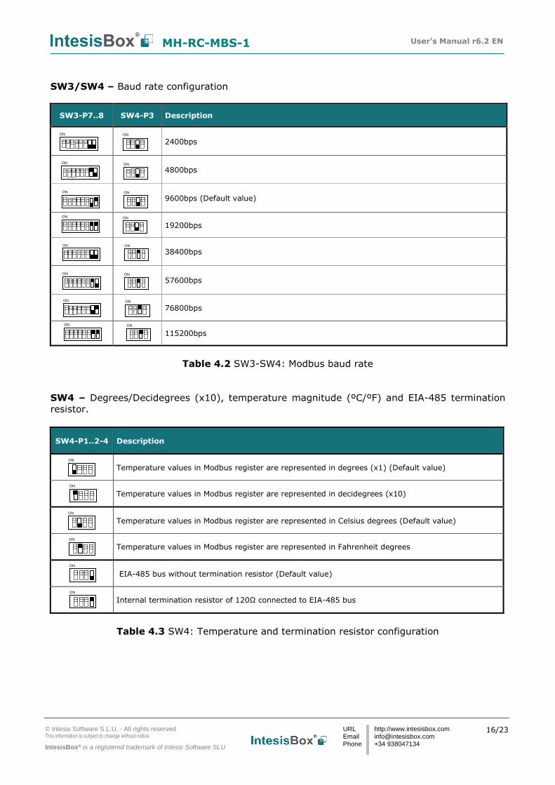
SW3/SW4 – Baud rate configuration
SW3-P7..8 SW4-P3 Description
2400bps
4800bps
9600bps (Default value)
19200bps
38400bps
57600bps
76800bps
115200bps
Table 4.2 SW3-SW4: Modbus baud rate
SW4 – Degrees/Decidegrees (x10), temperature magnitude (ºC/ºF) and EIA-485 termination
resistor.
Table 4.3 SW4: Temperature and termination resistor configuration
SW4-P1..2-4 Description
Temperature values in Modbus register are represented in degrees (x1) (Default value)
Temperature values in Modbus register are represented in decidegrees (x10)
Temperature values in Modbus register are represented in Celsius degrees (Default value)
Temperature values in Modbus register are represented in Fahrenheit degrees
EIA-485 bus without termination resistor (Default value)
Internal termination resistor of 120Ω connected to EIA-485 bus
ON
ON
ON
ON
ON
ON
ON ON
ON ON
ON ON
ON ON
ON ON
ON ON
ON ON
ON ON

MH-RC-MBS-1 User’s Manual r6.2 EN
© Intesis Software S.L.U. - All rights reserved This information is subject to change without notice
IntesisBox® is a registered trademark of Intesis Software SLU
URL EmailPhone
http://www.intesisbox.com [email protected] +34 938047134
17/23
SW3 – Modbus Slave address
Table 4.4 SW3: Modbus slave address
Add
SW3-P1..6
Add
SW3-P1..6
Add
SW3-P1..6
Add
SW3-P1..6
Add
SW3-P1..6
0
13
26
39
52
1
14
27
40
53
2
15
28
41
54
3
16
29
42
55
4
17
30
43
56
5
18
31
44
57
6
19
32
45
58
7
20
33
46
59
8
21
34
47
60
9
22
35
48
61
10
23
36
49
62
11
24
37
50
63
12
25
38
51
ON
ON
ON
ON
ON
ON
ON
ON
ON
ON
ON
ON
ON
ON
ON
ON
ON
ON
ON
ON
ON
ON
ON
ON
ON
ON
ON
ON
ON
ON
ON
ON
ON
ON
ON
ON
ON
ON
ON
ON
ON
ON
ON
ON
ON
ON
ON
ON
ON
ON
ON
ON
ON
ON
ON
ON
ON
ON
ON
ON
ON
ON
ON
ON

MH-RC-MBS-1 User’s Manual r6.2 EN
© Intesis Software S.L.U. - All rights reserved This information is subject to change without notice
IntesisBox® is a registered trademark of Intesis Software SLU
URL EmailPhone
http://www.intesisbox.com [email protected] +34 938047134
18/23
4.4 Implemented Functions
MH-RC-MBS-1 implements the following standard Modbus functions:
3: Read Holding Registers
4: Read Input Registers
6: Write Single Register
16: Write Multiple Registers (Despite this function is allowed, the interface does not
allow to write operations on more than 1 register with the same request, this means that
length field should be always be 1 when this function is being used in case of writing)
4.5 Device LED indicator
The device includes two LED indicators to show all the possible operational states. In the
following table there are written the indicators which can be performed and their meaning.
L1 (green LED)
Device status LED indication ON / OFF Period Description
During not normal operation
LED blinking 500ms ON / 500ms OFF Communication error
During normal operation
LED flashing 100ms ON / 1900ms OFF Normal operation (configured and working properly)
L2 (red LED)
Device status LED indication ON / OFF Period Description
During not normal operation
LED Pulse 3sec ON / --- OFF Under voltage
L1 (green LED) & L2 (red LED)
Device status LED indication ON / OFF Period Description
During normal operation
LED Pulse 5sec ON / --- OFF Device Start-up
During not normal operation
LED alternatively
blinking 500ms ON / 500ms OFF Flash checksum not OK

MH-RC-MBS-1 User’s Manual r6.2 EN
© Intesis Software S.L.U. - All rights reserved This information is subject to change without notice
IntesisBox® is a registered trademark of Intesis Software SLU
URL EmailPhone
http://www.intesisbox.com [email protected] +34 938047134
19/23
4.6 EIA-485 bus. Termination resistors and Fail Safe Biasing
mechanism
EIA-485 bus requires a 120Ω terminator resistor at each end of the bus to avoid signal
reflections.
In order to prevent fail status detected by the receivers, which are “listening” the bus, when all
the transmitters’ outputs are in three-state (high impedance), it is also required a fail-safe
biasing mechanism. This mechanism provides a safe status (a correct voltage level) in the bus
when all the transmitters’ outputs are in three-state. This mechanism must be supplied by the
Modbus Master.
The MH-RC-MBS-1 device includes an on-board terminator resistor of 120Ω that can be
connected to the EIA-485 bus by using DIP-switch SW4.
Some Modbus RTU EIA-485 Master devices can provide also internal 120Ω terminator resistor
and/or fail safe biasing mechanism (Check the technical documentation of the Master device
connected to the EIA-485 network in each case).

MH-RC-MBS-1 User’s Manual r6.2 EN
© Intesis Software S.L.U. - All rights reserved This information is subject to change without notice
IntesisBox® is a registered trademark of Intesis Software SLU
URL EmailPhone
http://www.intesisbox.com [email protected] +34 938047134
20/23
5. Mechanical and electrical features
Enclosure
Plastic, type PC (UL 94 V-0) Net dimensions (dxwxh): 93 x 53 x 58 mm / 3.7” x 2.1” x 2.3” Color: Light Grey. RAL 7035
Operation Temperature
0ºC to +60ºC
Weight 85 g. Stock Temperature
-20ºC to +85ºC
Mounting Wall DIN rail EN60715 TH35.
Operational Humidity
<95% RH, non-condensing
Terminal Wiring (for low-voltage signals)
For terminal: solid wires or stranded wires (twisted or with ferrule)
1 core: 0.5mm2… 2.5mm2 2 cores: 0.5mm2… 1.5mm2
3 cores: not permitted
Stock Humidity <95% RH, non-condensing
Modbus RTU port
1 x Serial EIA485 Plug-in screw terminal block (2 poles):
A, B Compatible with Modbus RTU EIA-485 networks
Isolation voltage 1500 VDC
AC unit port
1 x XY bus Plug-in screw terminal block (2 poles):
X, Y Compatible with Mitsubishi Heavy Industries networks
Isolation resistance
1000 MΩ
Switch 1
(SW1) 1 x DIP-Switch for AC features Protection IP20 (IEC60529)
Switch 3 (SW3)
1 x DIP-Switch for Modbus RTU settings
LED indicators 2 x Onboard LED - Operational status
Switch 4 (SW4)
1 x DIP-Switch for extra functions
EIA-485
Port
AC Unit
connection
DIP
Switch SW1
DIP
Switch SW3
LED
Indicators
DIP
Switch SW4

MH-RC-MBS-1 User’s Manual r6.2 EN
© Intesis Software S.L.U. - All rights reserved This information is subject to change without notice
IntesisBox® is a registered trademark of Intesis Software SLU
URL EmailPhone
http://www.intesisbox.com [email protected] +34 938047134
21/23
6. List of supported AC Unit Types.
A list of Mitsubishi Heavy Industries indoor unit model’s references compatible with MH-RC-
MBS-1 and its available features can be found on this link:
https://www.intesisbox.com/intesis/support/compatibilities/IntesisBox_MH-RC-xxx-1_AC_Compatibility.pdf

MH-RC-MBS-1 User’s Manual r6.2 EN
© Intesis Software S.L.U. - All rights reserved This information is subject to change without notice
IntesisBox® is a registered trademark of Intesis Software SLU
URL EmailPhone
http://www.intesisbox.com [email protected] +34 938047134
22/23
7. Error Codes
Error Code
Modbus
Error in
Remote
Controller
Error Description
0 N/A No active error
1 E1 Remote controller communication error
2 E2 Duplicated indoor unit address
3 E3 Outdoor unit signal line error
5 E5 Communication error during operation
6 E6 Indoor heat exchanger temperature thermistor anomaly
7 E7 Indoor return air temperature thermistor anomaly
8 E8 Heating overload operation
9 E9 Drain trouble
10 E10 Excessive number of indoor units (more than 17) by controlling one
remote controller
12 E12 Address setting error by mixed setting method
14 E14 Communication error between master and slave indoor units
16 E16 Indoor fan motor anomaly
19 E19 Indoor unit operation check, drain motor check setting error
28 E28 Remote controller temperature thermistor anomaly
30 E30 Unmatched connection of indoor and outdoor unit
31 E31 Duplicated outdoor unit address No.
32 E32 Open L3 Phase on power supply at primary side
33 E33 Inverter primary current error
35 E35 Cooling overload operation
36 E36 Discharge pipe temperature error
37 E37 Outdoor heat exchanger temperature thermistor anomaly
38 E38 Outdoor/Ambient air temperature thermistor anomaly
39 E39 Discharge pipe temperature thermistor anomaly
40 E40 High pressure error
41 E41 Power transistor overheat
42 E42 Current cut
43 E43 Excessive number of indoor units connected, excessive total capacity of
connection
45 E45 Communication error between inverter PCB and outdoor control PCB
46 E46 Mixed address setting methods coexistent in same network
47 E47 Inverter over-current error
48 E48 Outdoor DC fan motor anomaly
49 E49 Low pressure anomaly
51 E51 Inverter anomaly
53 E53 Suction pipe temperature thermistor anomaly
54 E54 High/Low pressure sensor anomaly
55 E55 Underneath temperature thermistor anomaly
56 E56 Power transistor temperature thermistor anomaly
57 E57 Insufficient in refrigerant amount or detection of service valve closure
58 E58 Anomalous compressor by loss of synchronism
59 E59 Compressor startup failure
60 E60 Rotor position detection failure / Anomalous compressor rotor lock
61 E61 Communication error between the master unit and slave units
63 E63 Emergency stop
65532
(-4) N/A
Initialization process (around 2min) before normal operation starts. This
error appears in case that MH-RC-MBS-1 is set as Master.
65535
(-1) N/A
Communication error of MH-RC-MBS-1 or Remote controller with the AC
unit.

MH-RC-MBS-1 User’s Manual r6.2 EN
© Intesis Software S.L.U. - All rights reserved This information is subject to change without notice
IntesisBox® is a registered trademark of Intesis Software SLU
URL EmailPhone
http://www.intesisbox.com [email protected] +34 938047134
23/23
In case to detect an error code not listed, contact your closest Mitsubishi Heavy Industries
technical support service.