rc cars & trucks - carid the nimh battery 8. troubleshooting guide problem cause remedy •only...
TRANSCRIPT

1. Before Using The RS10XT
2. Technical Data
3. Main Features
Thank you for purchasing the Redcat Racing RS10XT rock crawler.
The RS10XT is a hobby grade vehicle and is not a toy. Please read the entire manual before attempting to operate this vehicle.
Before running the RS10XT, please look over the entire vehicle to ensure there are no damaged or loose parts. Once the vehicle has been used, we can only assume broken parts are a result of improper use. Be sure to check the vehicle over before use.
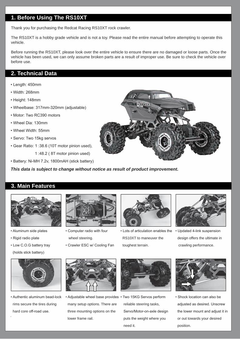
• Length: 450mm
• Width: 268mm
• Height: 148mm
• Wheelbase: 317mm-320mm (adjustable)
• Motor: Two RC390 motors
• Wheel Dia: 130mm
• Wheel Width: 55mm
• Servo: Two 15kg servos
• Gear Ratio: 1 :38.6 (10T motor pinion used),
1 :48.2 ( 8T motor pinion used)
• Battery: Ni-MH 7.2v, 1800mAH (stick battery)
This data is subject to change without notice as result of product improvement.
• Aluminum side plates
• Rigid radio plate
• Low C.O.G battery tray
(holds stick battery)
• Computer radio with four
wheel steering.
• Crawler ESC w/ Cooling Fan
• Lots of articulation enables the
RS10XT to maneuver the
toughest terrain.
• Updated 4-link suspension
design offers the ultimate in
crawling performance.
• Authentic aluminum bead-lock
rims secure the tires during
hard core off-road use.
• Adjustable wheel base provides
many setup options. There are
three mounting options on the
lower frame rail.
• Two 15KG Servos perform
reliable steering tasks,
Servo/Motor-on-axle design
puts the weight where you
need it.
• Shock location can also be
adjusted as desired. Unscrew
the lower mount and adjust it in
or out towards your desired
position.
4. Using the 2.4GHz radio system
-2.4GHz transmitter and receiver.
- Full functional, computer transmitter, with LCD screen.
- Four steering modes for extreme versatility.
-Always remove batteries from this product when not in use.
-Do not mix old and new batteries. Do not mix alkaline batteries,
standard (carbon-zinc) or rechargeable (nickel-cadmium) batteries.
-Slide out the battery cover to expose the empty battery compartment. Insert four AA size batteries ensuring the (+) side of each battery corresponds with the (+) mark on the battery tray.
-Do not damage or deform the antenna on the transmitter or receiver, this may cause signal loss.
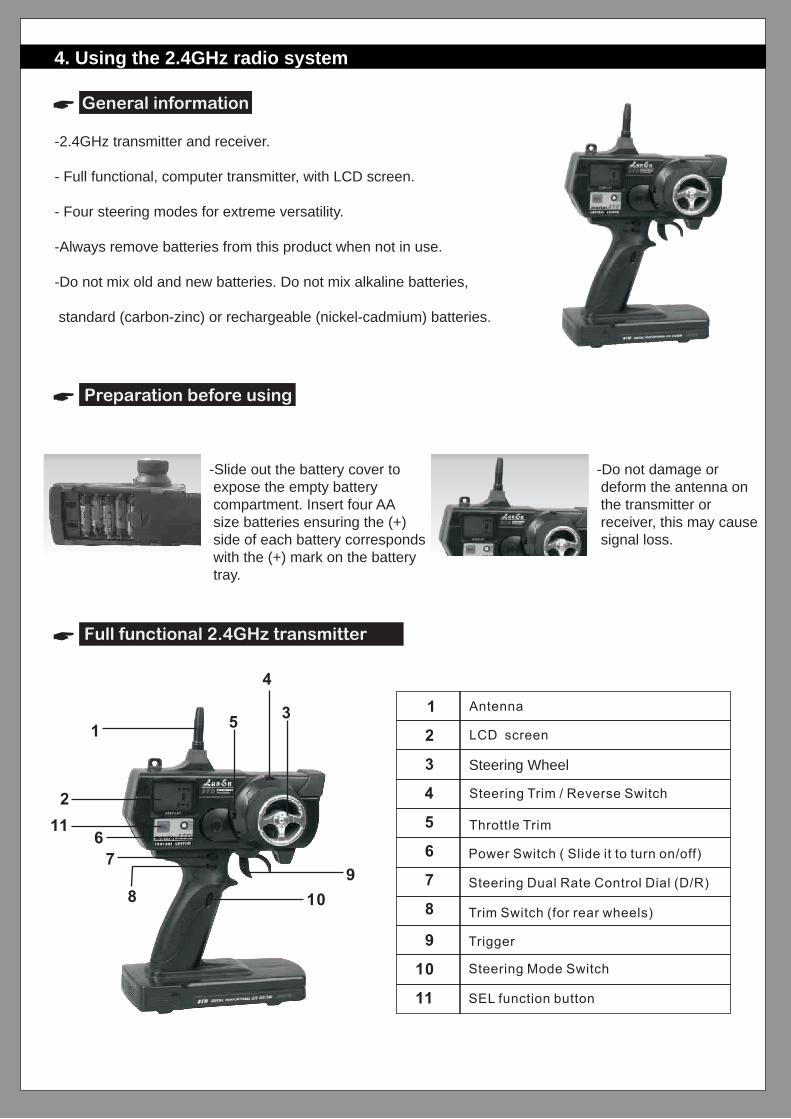
Full functional 2.4GHz transmitter
Preparation before using
General information
Steering Wheel
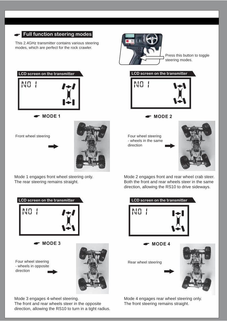
Full function steering modes
This 2.4GHz transmitter contains various steering modes, which are perfect for the rock crawler.
Press this button to toggle steering modes.
LCD screen on the transmitter LCD screen on the transmitter
LCD screen on the transmitter LCD screen on the transmitter
Front wheel steering Four wheel steering - wheels in the same direction
Mode 1 engages front wheel steering only. The rear steering remains straight.
Mode 2 engages front and rear wheel crab steer. Both the front and rear wheels steer in the same direction, allowing the RS10 to drive sideways.
Mode 3 engages 4-wheel steering. The front and rear wheels steer in the opposite direction, allowing the RS10 to turn in a tight radius.
Mode 4 engages rear wheel steering only. The front steering remains straight.
Four wheel steering - wheels in opposite direction
Rear wheel steering
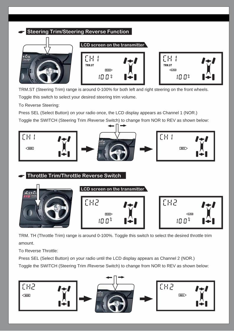
Steering Trim/Steering Reverse Function
Throttle Trim/Throttle Reverse Switch
LCD screen on the transmitter
LCD screen on the transmitter
TRM.ST (Steering Trim) range is around 0-100% for both left and right steering on the front wheels.
Toggle this switch to select your desired steering trim volume.
TRM. TH (Throttle Trim) range is around 0-100%. Toggle this switch to select the desired throttle trim
amount.
To Reverse Throttle:
Press SEL (Select Button) on your radio until the LCD display appears as Channel 2 (NOR.)
Toggle the SWITCH (Steering Trim /Reverse Switch) to change from NOR to REV as shown below:
To Reverse Steering:
Press SEL (Select Button) on your radio once, the LCD display appears as Channel 1 (NOR.)
Toggle the SWITCH (Steering Trim /Reverse Switch) to change from NOR to REV as shown below:
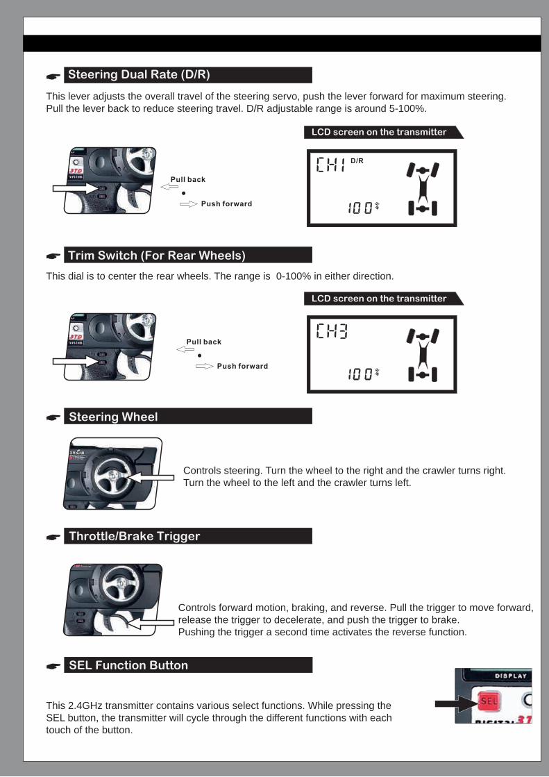
Steering Dual Rate (D/R)
Trim Switch (For Rear Wheels)
Steering Wheel
Throttle/Brake Trigger
SEL Function Button
LCD screen on the transmitter
LCD screen on the transmitter
This lever adjusts the overall travel of the steering servo, push the lever forward for maximum steering. Pull the lever back to reduce steering travel. D/R adjustable range is around 5-100%.
This dial is to center the rear wheels. The range is 0-100% in either direction.
Controls steering. Turn the wheel to the right and the crawler turns right. Turn the wheel to the left and the crawler turns left.
Controls forward motion, braking, and reverse. Pull the trigger to move forward, release the trigger to decelerate, and push the trigger to brake.Pushing the trigger a second time activates the reverse function.
This 2.4GHz transmitter contains various select functions. While pressing the SEL button, the transmitter will cycle through the different functions with each touch of the button.
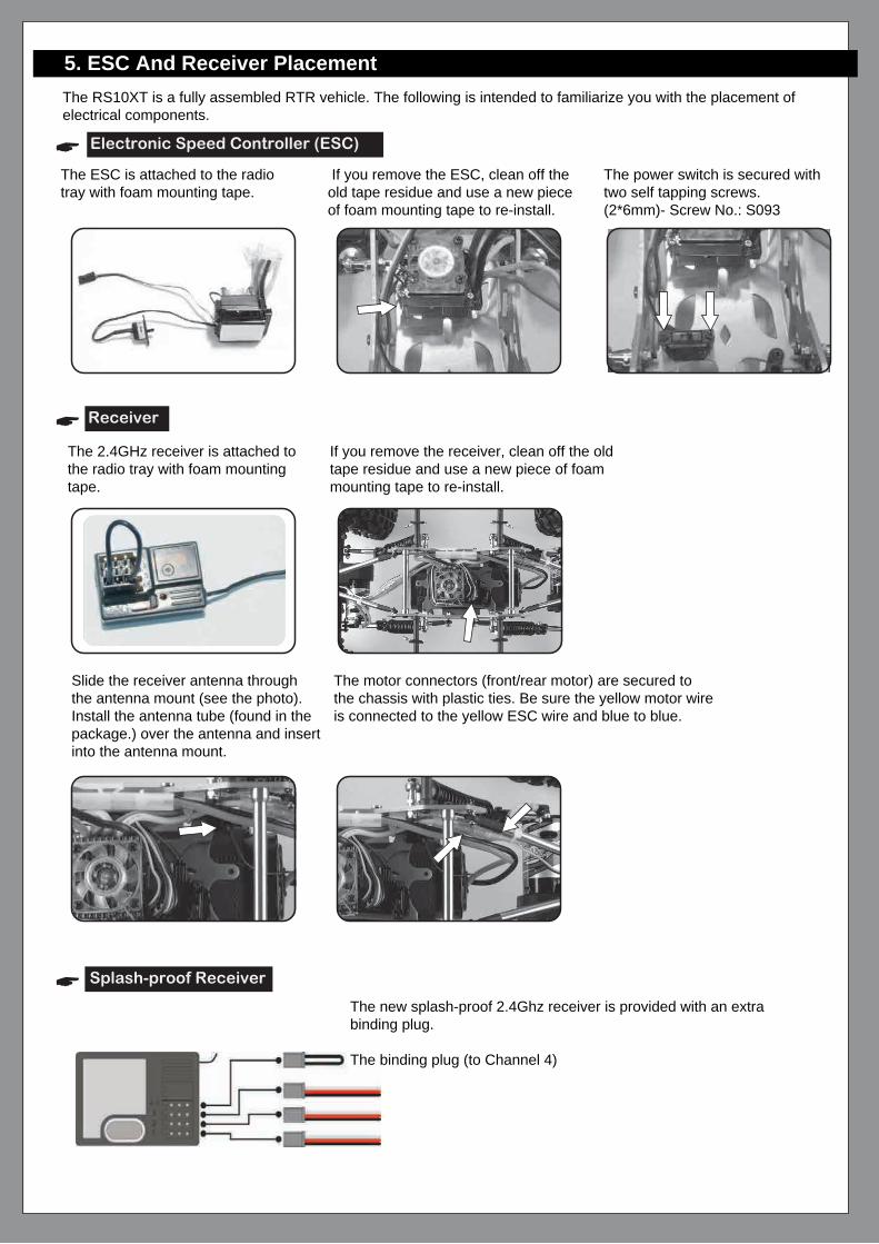
5. ESC And Receiver Placement The RS10XT is a fully assembled RTR vehicle. The following is intended to familiarize you with the placement of electrical components.
The ESC is attached to the radio tray with foam mounting tape.
If you remove the ESC, clean off the old tape residue and use a new piece of foam mounting tape to re-install.
The power switch is secured with two self tapping screws. (2*6mm)- Screw No.: S093
Electronic Speed Controller (ESC)
Receiver
Splash-proof Receiver
The 2.4GHz receiver is attached to the radio tray with foam mounting tape.
If you remove the receiver, clean off the old tape residue and use a new piece of foam mounting tape to re-install.
Slide the receiver antenna throughthe antenna mount (see the photo).Install the antenna tube (found in the package.) over the antenna and insert into the antenna mount.
The new splash-proof 2.4Ghz receiver is provided with an extrabinding plug.
The binding plug (to Channel 4)
The motor connectors (front/rear motor) are secured to the chassis with plastic ties. Be sure the yellow motor wire is connected to the yellow ESC wire and blue to blue.

How to bind the receiver with the transmitter?1) Insert the bind plug into Channel 4 before switching on the receiver.
2) Switch on the receiver. The LED light will flash.
4) Press and hold the SEL button on the transmitter.
The LED on the receiver will continue to flash. The radio is binding.
When the receiver's LED is lit solid, binding is complete.
Note: Repeat the above steps if binding fails.
5) Center the steering trim on the transmitter after binding is complete to set fail safe.
6) Remove the binding plug.
LED Indicator:• RAPID FLASHING: BINDING IS IN OPERATION.
• SLOW FLASHING: NO SIGNAL WAITING FOR OPERATION
• SOLID LIGHT: IN OPERATION
• NO LIGHT: RECEIVER IS OFF, BATTERY IS DEAD OR MISSING, RECEIVER IS
DISCONNECTED OR BROKEN
6. Turning the vehicle on/off
Transmitter Power Switch
To turn the vehicle on:1. Switch on the transmitter.2. Switch on the ESC power switch.
To turn off the vehicle:1. Switch off the ESC power switch.2. Switch off the transmitter.Remember to remove the batteries from the vehicle and transmitter when not in use.
ESC power switch

7. Charging the NiMH battery
8. Troubleshooting Guide
PROBLEM CAUSE REMEDY
• Only use NiMH specific chargers to chargeNi-MH battery packs.
• Never overcharge your Ni-MH battery packs.• Never charge the battery pack unattended.• Always use the battery after it is fully charged.
Never tempt to use this charger to charge the batteries of your transmitter.
1) Transmitter or receiver is off.2) Batteries are not placed correctly in the
transmitter.3) Battery pack on the car is low.4) Transmitter and receiver are not bound
correctly.
Your RS10XT rock crawler
fails to move.
Servo does not operate
normally.
Radio operates erratically.
Operating range is short.
Motor does not work.
The crawler moves when
turned on.
Steering works, but throttle
does not work.
1) Turn both transmitter and receiver on.2) Correctly align batteries in the transmitter.3) Charge the battery pack.4) Bind the transmitter and receiver.
1) Transmitter and/or receiver batteriesare low.
2) Servo gears stripped or otherwisedamaged.
1) Replace/recharge transmitter and/or receiverbatteries.
2) Replace servo or servo gears.
1) Transmitter batteries are low.2) Radio is damaged from dropping.
1) Replace transmitter batteries.2) Replace transmitter/receiver.
1) Transmitter batteries are low. 1) Replace transmitter batteries.
1) Motor wires loose or damaged. 1) Double-check motor wires. Repair/replaceas necessary.
1) Throttle Trim is out of adjustment. 1) Adjust Throttle Trim again.
1) Motor wires are loose or damaged.2) ESC is incorrectly plugged into the
receiver.
1) Check motor wires. Plug in correctly and/orrepair damage.
2) Plug the ESC into the receiver correctly.
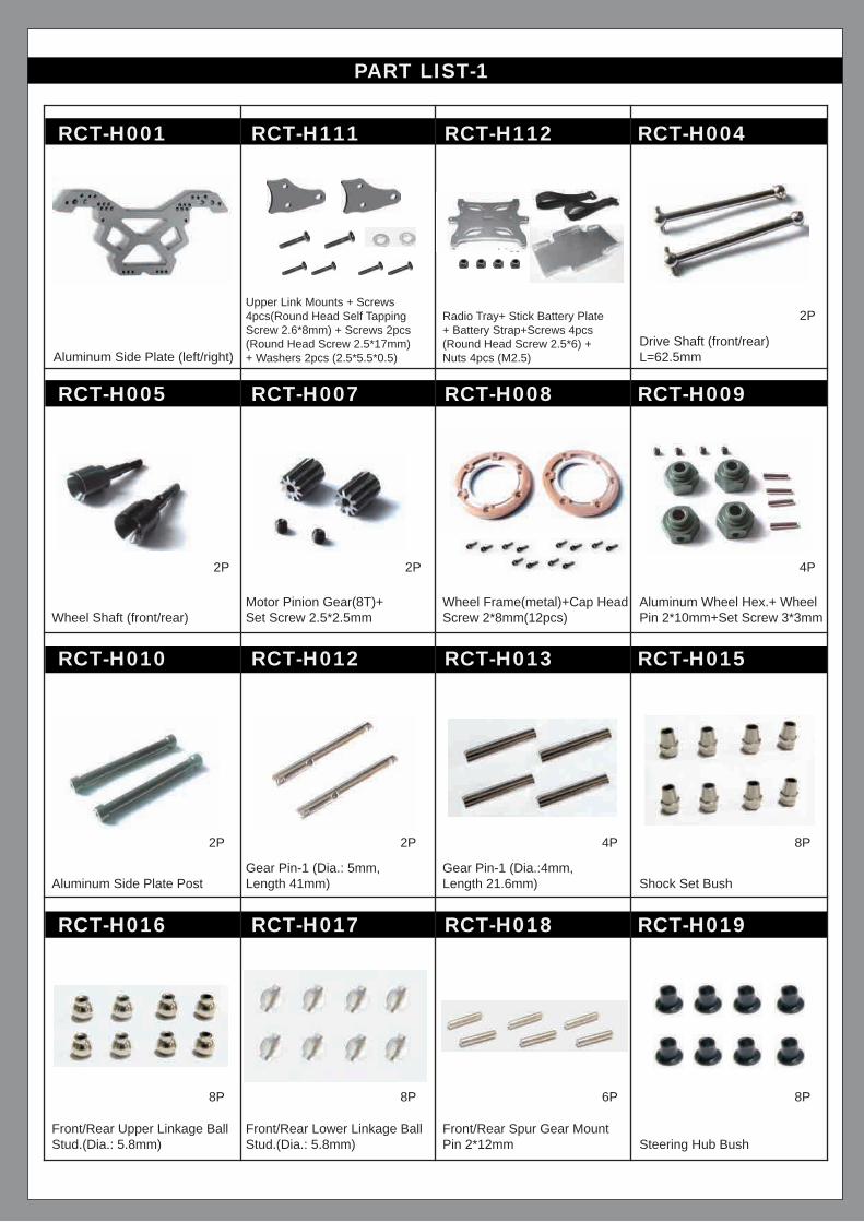
PART LIST-1
RCT-H001 RCT-H111 RCT-H112 RCT-H004
RCT-H005 RCT-H007 RCT-H008 RCT-H009
RCT-H010 RCT-H012 RCT-H013 RCT-H015
RCT-H016 RCT-H017 RCT-H018 RCT-H019
Aluminum Side Plate (left/right)
Wheel Shaft (front/rear)Motor Pinion Gear(8T)+ Set Screw 2.5*2.5mm
Wheel Frame(metal)+Cap HeadScrew 2*8mm(12pcs)
Aluminum Wheel Hex.+ Wheel Pin 2*10mm+Set Screw 3*3mm
Aluminum Side Plate PostGear Pin-1 (Dia.: 5mm, Length 41mm)
Gear Pin-1 (Dia.:4mm, Length 21.6mm) Shock Set Bush
Front/Rear Upper Linkage BallStud.(Dia.: 5.8mm)
Front/Rear Lower Linkage BallStud.(Dia.: 5.8mm)
Front/Rear Spur Gear MountPin 2*12mm Steering Hub Bush
Upper Link Mounts + Screws 4pcs(Round Head Self Tapping Screw 2.6*8mm) + Screws 2pcs (Round Head Screw 2.5*17mm) + Washers 2pcs (2.5*5.5*0.5)
Radio Tray+ Stick Battery Plate+ Battery Strap+Screws 4pcs (Round Head Screw 2.5*6) + Nuts 4pcs (M2.5)
Drive Shaft (front/rear) L=62.5mm
2P
2P 2P 4P
2P 2P 8P4P
8P 8P 8P6P

PART LIST-2
RCT-H020A RCT-H021 RCT-H022 3338-H016
H007 H009 H016 H032
H036 H049 RCT-T001 RCT-T003
RCT-T004 RCT-T005 RCT-T006 RCT-T020
Linkage Bar Bolt
Ball Bearing 5*11*4mm Ball Bearing 10*15*4mmSteering Linkage Ball Stud.(Dia.:5.8mm) Ball Bearing 4*7*2.5mm
Ball Bearing 8*16*5mm Ball Bearing 4*9*4mm
Front/rear Lower Linkage Set+4PCS of Ball Stud. (RCT-H017)
Front/rear Steering LinkageSet+4pcs of Ball Stud. (H016)
Front/rear Servo Linkage Set+4PCS of Ball Stud. (H016) Front/Rear Shock Set Front/Rear Spur Gear Complete
Front/Rear Upper Linkage Set + 3pcs of Ball Stud.(RCT-H016)+1pcs of Ball Stud. (RCT-H017)
Spring Pad( Inner Dia.:2.5mm)(apply to motor with screws)
Washer( 2.5*5.5*0.5mm) 8PWasher (3.1*6*0.5mm) 8P
Gear Shaft Outdrive Cup {front/rear)
2P
6P 4P 8P 6P
6P 6P
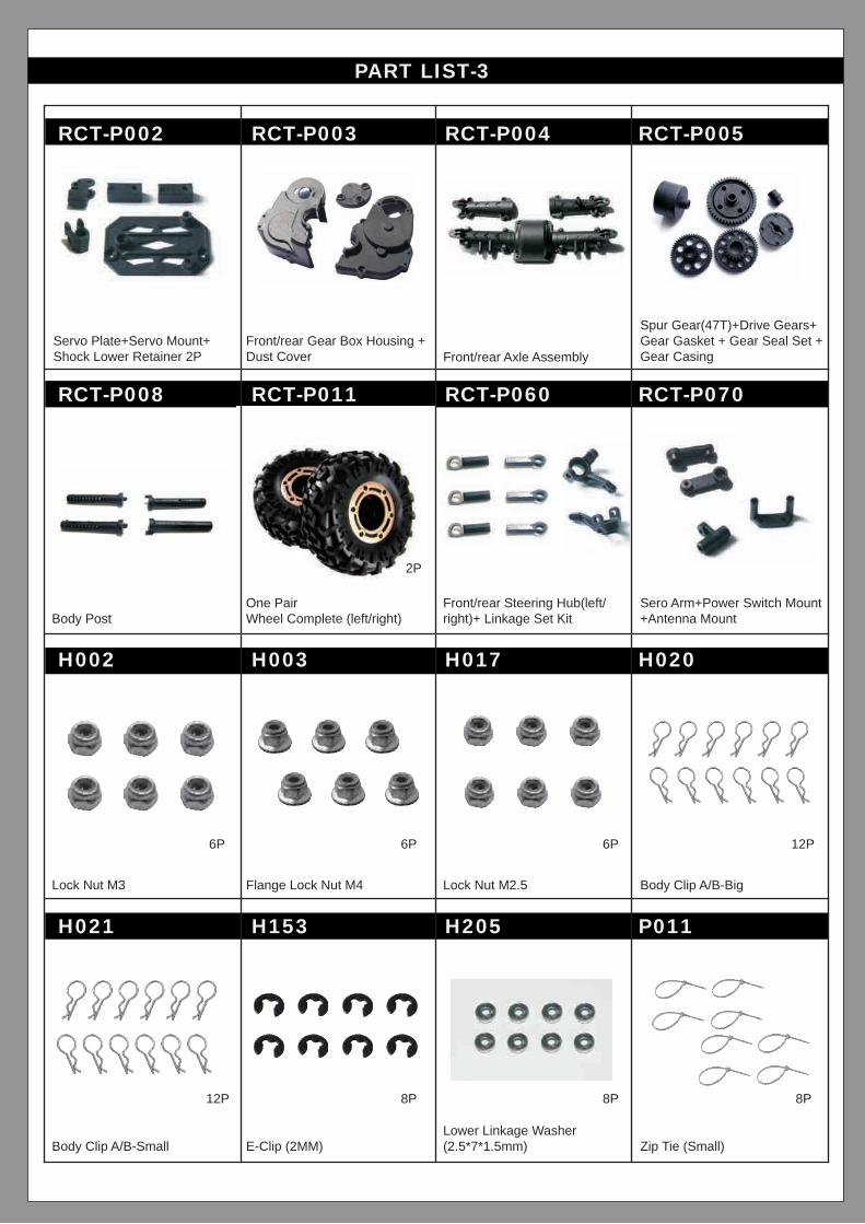
PART LIST-3
RCT-P002 RCT-P003 RCT-P004 RCT-P005
RCT-P008 RCT-P011 RCT-P060 RCT-P070
H002 H003 H017 H020
H021 H153 H205 P011
Servo Plate+Servo Mount+Shock Lower Retainer 2P
Body PostFront/rear Steering Hub(left/right)+ Linkage Set Kit
Sero Arm+Power Switch Mount+Antenna Mount
Lock Nut M3 Flange Lock Nut M4 Lock Nut M2.5 Body Clip A/B-Big
Body Clip A/B-Small E-Clip (2MM)Lower Linkage Washer(2.5*7*1.5mm) Zip Tie (Small)
Front/rear Gear Box Housing + Dust Cover Front/rear Axle Assembly
Spur Gear(47T)+Drive Gears+Gear Gasket + Gear Seal Set + Gear Casing
6P 6P 12P6P
12P 8P 8P8P
2P
One PairWheel Complete (left/right)

PART LIST-4
P019 P100 01003-CHARGER-T E600T
E600R HX-2200MH-T 3CH-24GHz-RADIO E710
E401 HX-15CS RCT-T007 RCT-H106
S016 S018 S028 S029
Receiver Antenna Tube
RC390 Motor (Rear)Blue Wire (-), Yellow Wire(+)
Optional Reachable NiMh Battery Pack 7.2V, 2200mAh
3 Channel 2.4GHz Radio with Receiver Receiver
Crawler ESC 15KGs Metal Gear ServoOptional Front/rear Diff. Assembly
Optional Steer Gear Kit (motor pinion is 10T)
Set Screw (M3*3mm)Round Head Self Tapping Screw (2.6*8mm)
Round HeadScrew (2.5*14mm)
Round Head Self Tapping Screw (2.6*10mm)
Body Post PadU.S. Standard Ni-MH Battery Charger
RC390 Motor (Front)Yellow Wire (-), Blue Wire(+)
12P
12P 12P 12P 12P
2P

PART LIST-5
S030 S031 S059 S060
Round Head Self TappingScrew (3*10mm) Cap Head Screw (2*8mm)
Round HeadScrew (3*8mm)
Round HeadScrew (2.5*12mm)
12P 12P 12P 12P
S063 S089 S093 S098
Round Head Screw (2.5*17mm)
Round Head Self Tapping Screw (2.6*6mm)
Round Head Self Tapping Screw (2*6mm)
Round HeadScrew (3*21mm)
12P 12P 12P 12P
S099 S100 S101 S102
Round Head Screw (3*14mm)
Round Head Screw (2.5*8mm)
Round HeadScrew (2.5*6mm)
Countersunk Self TappingScrew (2*6mm)
12P 12P 12P 12P
S104 S027 S015 S096
Round Head Screw (3*10mm)
Round Head Screw (2.5*10mm) Step Set Screw (3*3-2*7mm)
Round HeadScrew (3*24mm)
12P 12P 12P 12P
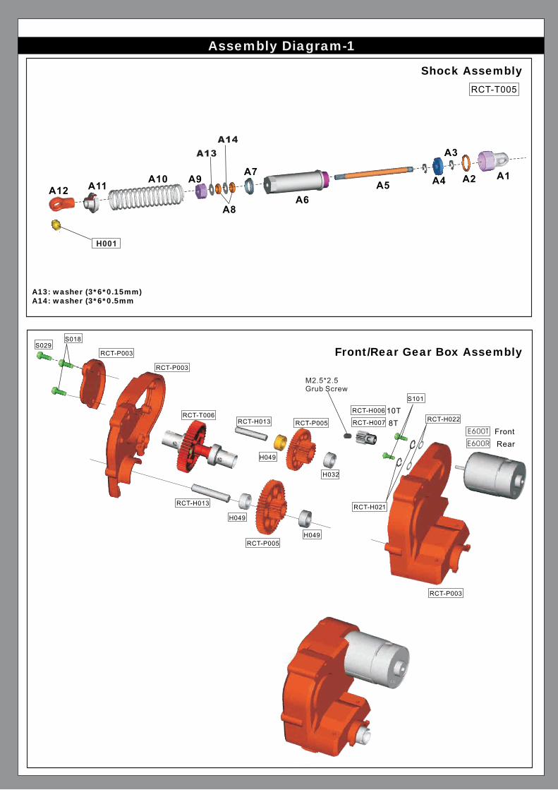
Assembly Diagram-1
Shock Assembly
Front/Rear Gear Box Assembly
A13: washer (3*6*0.15mm)A14: washer (3*6*0.5mm
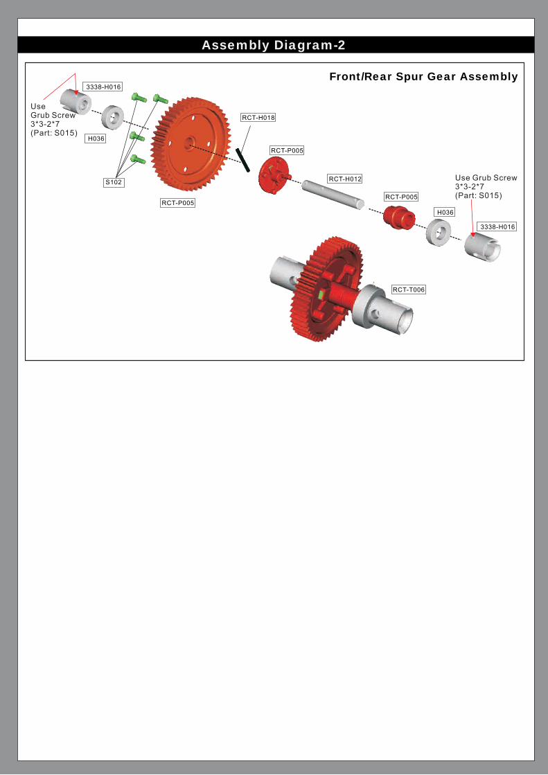
Assembly Diagram-2
Front/Rear Spur Gear Assembly


CENTER UNIT ASSEMBLY