introduction page 2, 3 - lightalarms · 2 lightalarms is proud to present its complete range of...
TRANSCRIPT


1
Introduction ..........................................................................Page 2, 3
Exit Signs
CH Series—Cold Cathode ..........................................................4, 5
CH XE Series, Steel Exit..............................................................6, 7
Emergency Lighting
RD CH Series ............................................................................8, 9
TBR CH Series........................................................................10, 11
MG CH Series ........................................................................12, 13
PG CH Series ........................................................................14, 15
PQ CH Series ........................................................................16, 17
PN CH, P12N CH Series ................................................................18
SN CH Series ..............................................................................19
Unit Heads / Matching Remote Heads
DR1130-CH Series ........................................................................20
ELF622-CH Series ........................................................................21
Lamp Data ........................................................................................22
Popular Options ................................................................................23
Accessories ................................................................................24, 25
Improved Diagnostics........................................................................26
Wire Size Guide ................................................................................27
Life Safety ..................................................................................28-30
Terms and Conditions ......................................................................31
Limited Warranty ............................................................................32
TABLE OF CONTENTS

2
Lightalarms is proud to present
its complete range of Chicago-approved
life safety equipment. A leading
manufacturer of emergency lighting
and exit signage, Lightalarms has been
supplying innovative, reliable emergency
lighting in the U.S. since 1953 and
is pleased to continue this tradition
with our newly-expanded Chicago
product offering.
CITY OF CHICAGO—APPROVED

3
When it comes to life safety, there can be
no compromise. The Lightalarms products
on the following pages are designed,
manufactured and tested to meet some
of the most demanding standards in
North America—Chicago standards.
The complete line of Lightalarms life
safety products meets or exceeds the
requirements of UL 924, NFPA 101,
Life Safety Code, NEC and ICC standards.
In addition, you will now find UL approved,
recessed equipment, for use in “City of
Chicago Environmental Airspaces” (CCEA).
This mark is recognized by the Chicago
Department of Buildings, Electrical Division.
From high-end architectural to industrial
installations, for new construction and
retrofit projects, there’s a Lightalarms
product to meet your specifications.
Lightalarms—lighting the way to safetysince 1953.
SETTING THE STANDARD

·Torsion springs on the trim plate slide into the back box to provide a tight sealbetween both.
·The modular design results in easy, efficient installation at the job site.
EASY INSTALLATION
Input AC FrequencyPower Consumption
PowerVoltage in Hertz
(in Watts)Factor
AC-Only Self-Powered
120 60 8.4 9.8 0.85277 60 8.5 9.9 0.86
ELECTRICAL DATA
FEATURES• RELIABILITY: The CH Series has a
3-year full warranty (excluding lamps).Cold-cathode fluorescent lamps have a3-year life expectancy.
• POWER REQUIREMENTS: 120/277 VAC,60Hz, 10-watts for single or double face signs.
• HOUSING: Die-cast aluminum housing,trim ring, trim plate and canopy.Standard brushed aluminum, white orblack finishes with other finishesavailable as an option (consult factory).The trim plate assembly is hinged toprovide easy access to the lamps,electronics and battery.
• TRIM PLATE: Choice of dome or pyramid trim plates.
• FACE PANEL: Virgin acrylic face plate is 3/8”, thin, silk-screened and computer-engraved to provide a flawless legend. Face plates are availablewith red letters on a white panel (single or double face).
• MODULAR DESIGN: Allows for quickinstallation in surface or recessedmounting without compromising aesthetics.
• CIRCUITRY: The two cold-cathode fluorescent lamps are driven indepen-dently by their own fused inverter/ballast circuits. This feature allows the sign to remain illuminated should a lamp or the driver circuit expire.Optional self-testing diagnostics areavailable on all self-powered models.
Die-Cast Aluminum, Cold-Cathode Edge-Lit, AC-Only or Self-Powered
Thin, sleek and efficient, the CH Series exit sign is a snap to install and complements any decor. Using high performance cold-cathode technology, the CH Series features state-of-the-art acrylic panels and precision etched lettering for maximum clarity, visibility and aesthetic appeal.
CH Series Cold Cathode
All mounting configurations use the same basic components. Inserting a trim ring allowsfor recessed mounting in walls or ceilings. Applying a canopy allows for surface mountingon ceilings or walls as back or end mount.
MOUNTING CONFIGURATION
4
NEW!NEW!
Dome Trim
Option
Pyramid trim

CH Series Cold Cathode
Dual Circuit ......................................................-2Self-Test/Diagnostic (Self-Powered Only)................-DFire Alarm Activated Flasher ............................-FAFFlasher/Buzzer (Self-Powered Only) ....................-FB
For special wording, contact factory.For special finishes, contact factory.
OPTIONS (Add suffix to Model No.)
Pendant, White .................................................. PW-*Pendant, Black.................................................... PB-*Replacement Lamp Assembly ........................ 061903
*Specify length of pendant required (12”, 24”, 36” etc.).
ACCESSORIES (Order as separate item)
Lamp
CH = Cold CathodeFluorescentLamp
Model
SED = AC-OnlySPED = Self-
Powered
Unit Color
W = WhiteA = Brushed
AluminumB = Black
Panel Type
RW = Red/White
Trim
D = Dome P = Pyramid
Options
See Chart.Stairs, No Arrow ................#2A #17AExit, No Arrow....................#3 #18Stairs, Arrow Right ............#5A -Exit, Arrow Right ................#6 -Stairs, Arrow Left ..............#8A -Exit, Arrow Left ..................#9 -Stairs, Double Arrow..........#11A #23AExit, Double Arrow ............#12 #24Stairs, Arrow Right and Left..- #20AExit, Arrow Right and Left ....- #21
Chicago DescriptionSingle Face
Double Face
®
Listed
ORDERING INFORMATIONExample: CH SED W RWD #2A
5
The self-test/diagnostic feature continuously monitors the inverter charger assembly and the battery. If a fault isindicated, the external service required indicator will illumi-nate. The internal fault indicators will then indicate thenature of the fault. The self-test/diagnostic will self-test for30 seconds every 30 days, 30 minutes every 60 days and 90 minutes annually. Meets NFPA 101 Life Safety Coderequirements for periodic testing.
SELF-TEST/DIAGNOSTIC FEATURE (Optional)
DIMENSIONS
1-1/8”
4” 2-1/2”
11-5/8”
4” 2-1/2”
2-7/8”
10”
3-1/4”
4-5/8”
13-7/8” 13-5/8”
5/8”
16-3/4”
6-1/4”
14”
Recessed Models
End Mount
Surface Models

FEATURES• RELIABILITY: The CH XE Series has a
three-year full warranty (excluding lamps).
• HOUSING: Rugged 20 gauge steel housingwith knockouts for universal mounting toany wall or ceiling box. Available housingcolors are off-white and black witha screened glass panel of red letters ona white background.
• LIGHT SOURCE: Incandescent signs are supplied with two long life 20WT6 dintermediate screw base incandescentlamps, uniquely angled to eliminate shadows on the face and provide uniformillumination. Also available with two compact fluorescent 7 watt lamps.
• POWER REQUIREMENTS: 120/277-Volts AC.
• SELF-POWERED UNITS- BATTERY
Sealed, maintenance-free long-life lead
- ELECTRONICSAutomatic, temperature-compensated,pulse type charger. Instantaneous, dust-tight transfer relay. Dual diagnosticindicator lights. Low voltage battery disconnect. Labor saving battery lock-out feature to facilitate one-stepinstallations.
Steel Exit Sign Incandescent or Fluorescent, AC-Only, AC/DC and Self-Powered
The CH XE Series is a steel exit sign designed for ease of installation. A fully universal exit, it is available in AC only, AC/DC and Self-Powered models. The removable side panel provides job site flexibility in changingsigns for either single or double face requirements.
CH XE Series
Pendant, White .................................................... PW- *Pendant, Black .................................................... PB- *Wire Guard (End or Ceiling Mount) ........................ WG5Wire Guard (AC - AC/DC only, Wall Mount) .......... WG12Wire Guard (Self-Powered, Wall Mount) .................. WG2
*Specify length of pendant required (12”, 24” 36” etc.).
ACCESSORIES (Order as separate item)
6
®
Listed
Input AC Voltage Input Power120 Vac Max. 40W
277 Vac Max. 40W
ELECTRICAL DATA
13"
14"
5 1/2" 15 1/4"
3 1/2"
18"
6"
20"17 1/2"
16 1/2"
13 1/2"
4 1/2"
10 1/4" 15"
9"
WG2
WG5 WG12

CH XE Series
7
DC LampOption
Blank = AC Only6 = 6VDC12 = 12VDC
HousingColor
W = WhiteB = Black
SeriesAC or AC/DC
CHX = AC OnlyCHXE = Self
Powered
Letter/FaceColor
RW = Redletters/White Face
Lamp Type
Blank = Incandescent
PL = Fluorescent
AC Input
Blank = 120 VAC277 = 277 VACStairs, No Arrow ................#2A #17A
Exit, No Arrow....................#3 #18Stairs, Arrow Right ............#5A -Exit, Arrow Right ................#6 -Stairs, Arrow Left ..............#8A -Exit, Arrow Left ..................#9 -Stairs, Double Arrow..........#11A #23AExit, Double Arrow ............#12 #24Stairs, Arrow Right and Left..- #20AExit, Arrow Right and Left ....- #21
Chicago DescriptionSingle Face Double Face
DIMENSIONS
SELF-POWERED
CANOPY
AC - AC/DC
ORDERING INFORMATIONExample: WCHXRW#2APL
FEATURES• RELIABILITY: The RD CH Series has
a three-year full warranty (excludinglamps).
• CONSTRUCTION: Construction of 20gauge steel with an mist-white backedenamel finish.Unit and lamp head color is pure whitewhen MR16 lamps are ordered.
• MOUNTING: Easily recesses into wall or ceiling. Mounting brackets includedfor installation in grid type suspendedceilings. Unit comes standard with 16”adjustable bar hangers. Furnished withELF622 heads with 6- or 12-volt lampsas specified.
• ELECTRONICS:- Automatic, temperature-compensated,
pulse-type charger.- High capacity, automatic, dust tight
instantaneous transfer relay.- Low voltage disconnect prevents over
discharge of battery. Automatic brownout protection is provided.
- Labor saving AC line latch preventsbattery discharge during installationto a non-energized circuit.
• CONTROLS:- Red charge monitor LED indicates
state of charge of the battery.- Amber AC-ON LED indicates AC power
is on.- Momentary test switch allows for quick
operational check of entire system.
• POWER REQUIREMENTS:- 120/277-Volt AC.
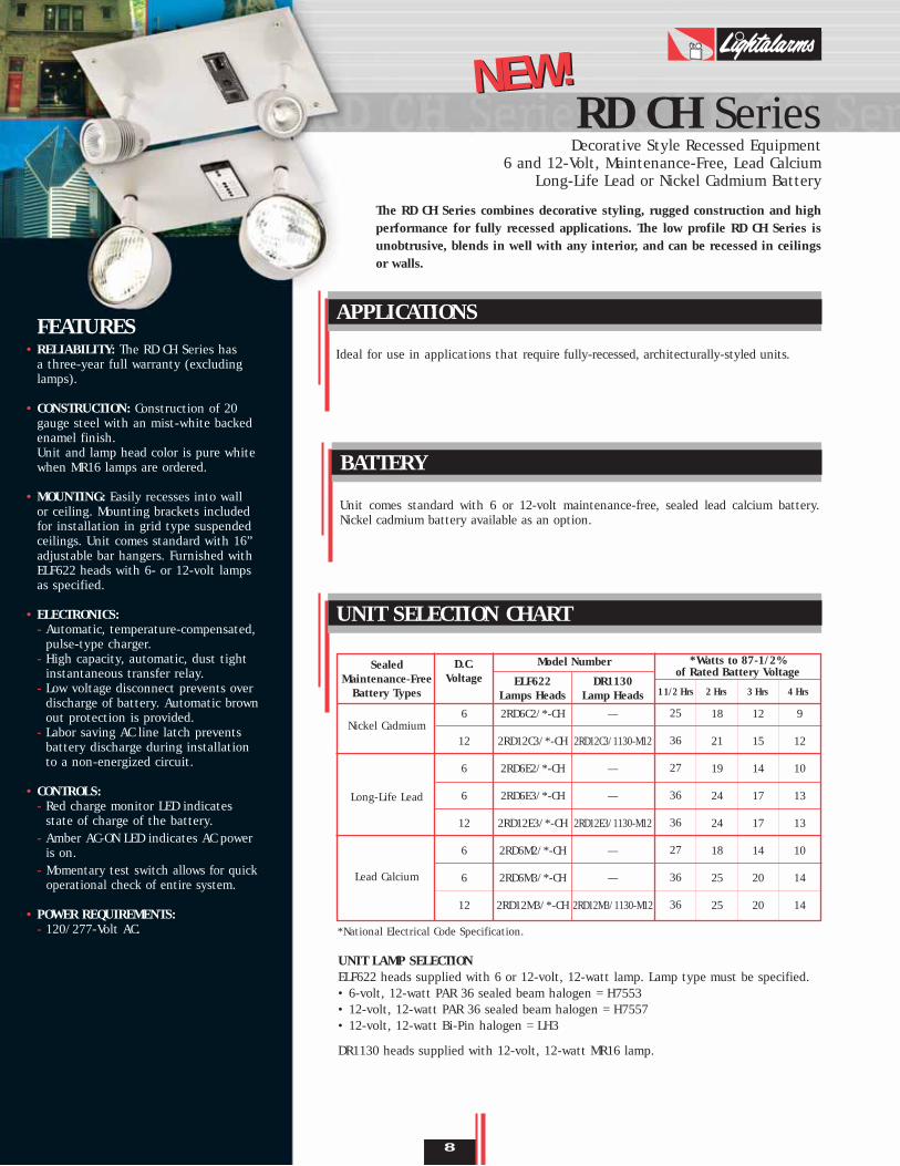
Decorative Style Recessed Equipment6 and 12-Volt, Maintenance-Free, Lead Calcium
Long-Life Lead or Nickel Cadmium Battery
The RD CH Series combines decorative styling, rugged construction and highperformance for fully recessed applications. The low profile RD CH Series isunobtrusive, blends in well with any interior, and can be recessed in ceilingsor walls.
RD CH Series
Ideal for use in applications that require fully-recessed, architecturally-styled units.
APPLICATIONS
Unit comes standard with 6 or 12-volt maintenance-free, sealed lead calcium battery.Nickel cadmium battery available as an option.
BATTERY
UNIT LAMP SELECTIONELF622 heads supplied with 6 or 12-volt, 12-watt lamp. Lamp type must be specified.• 6-volt, 12-watt PAR 36 sealed beam halogen = H7553• 12-volt, 12-watt PAR 36 sealed beam halogen = H7557• 12-volt, 12-watt Bi-Pin halogen = LH3
DR1130 heads supplied with 12-volt, 12-watt MR16 lamp.
UNIT SELECTION CHART
8
9
12
10
13
13
10
14
14
Sealed Maintenance-Free
Battery Types
D.C. Voltage
Model Number *Watts to 87-1/2% of Rated Battery Voltage
11/2 Hrs 2 Hrs 3 Hrs 4 Hrs
*National Electrical Code Specification.
ELF622Lamps Heads
DR1130Lamp Heads
2RD6C2/*-CH
2RD12C3/*-CH
2RD6E2/*-CH
2RD6E3/*-CH
2RD12E3/*-CH
2RD6M2/*-CH
2RD6M3/*-CH
2RD12M3/*-CH
—
2RD12C3/1130-M12
—
—
2RD12E3/1130-M12
—
—
2RD12M3/1130-M12
25
36
27
36
36
27
36
36
18
21
19
24
24
18
25
25
12
15
14
17
17
14
20
20
Nickel Cadmium
Long-Life Lead
Lead Calcium
6
12
6
6
12
6
6
12
NEW!NEW!

RD CH Series
ORDERING FORMAT
Supplied with ELF622 heads with 6 or 12-volt 12-watt, PAR36 lamp type as specified. DR1130heads are available on 12-volt units, supplied with12-watt MR16 lamps (see Unit Selection Chart).Unit and lamp head color is pure white whenMR16 lamps are ordered.
LAMP HEADS
DIMENSIONS
9
®
Listed
2 RD 12 C 3 - /LH3 -1130 -CH -M -ID
2................No. of Heads (0,1,2)
RD ............Series12..............DC Battery Backup
(6=6 VDC, 12=12 VDC)
C................Battery Type(M=Lead Calcium, E=Long-Life LeadC=Nickel Cadmium)
3................Capacity Indicator(See Unit Selection Chart)
/LH3 ..........Lamp Suffix (See Lamp Selection Chart P.22)
/1130 ........DR1130 Lighting Heads-CH ............City of Chicago Spec.-M..............Standard Mist White Finish-ID ............Improved Diagnostics (See Options)
Black Housing and Heads (replace “M” by)..................-BAmmeter or Voltmeter (choose only one) ........-A* or -V *Improved Diagnostics ..............................................-IDImprove Diagnostics, Non-Audible ........................-IDNATime Delay ............................................................-TD **Non-Standard Input Voltage ..............................Specify
* Not available with ID/IDNA option.** Not required when using the ID/IDNA option.
OPTIONS (Add suffix to Model No.)
Wire Guard ........................................................ WG6(ELF622 or DR1130 heads)27” Adjustable Bar Hangers .............................. BH-RDRemote Test Switch, Metal Faceplate...................... -RTS
ACCESSORIES (Order as separate item)
FEATURES• RELIABILITY: The TBR CH Series has a
three-year full warranty (excludinglamps).
• CONSTRUCTION: 18-gauge, steel, finished in mist white enamel. Provision for mounting up to three heads.Unit and lamp head color is pure white when MR16 lamps are ordered.
• MOUNTING: Lay-in installation in T-bargrid ceiling. Back box has removablecover for ease of installation and fullaccess to battery and charger.
• ELECTRONICS:- Automatic, temperature compensated,
pulse type charger.- High capacity, automatic, dust tight
instantaneous transfer relay.- Low voltage disconnect prevents
overdischarge of battery. Automatic brownout protection is provided.
- Labor saving AC line latch prevents battery discharge during installation to a non-energized circuit.
- Fused output circuit.
• CONTROLS:- Red charge monitor LED indicates state
of charge of the battery.- Amber AC-ON LED indicates AC power
is on.- Momentary test switch allows for quick
operational check of entire system.
• POWER REQUIREMENTS:- 120/277-Volt AC.
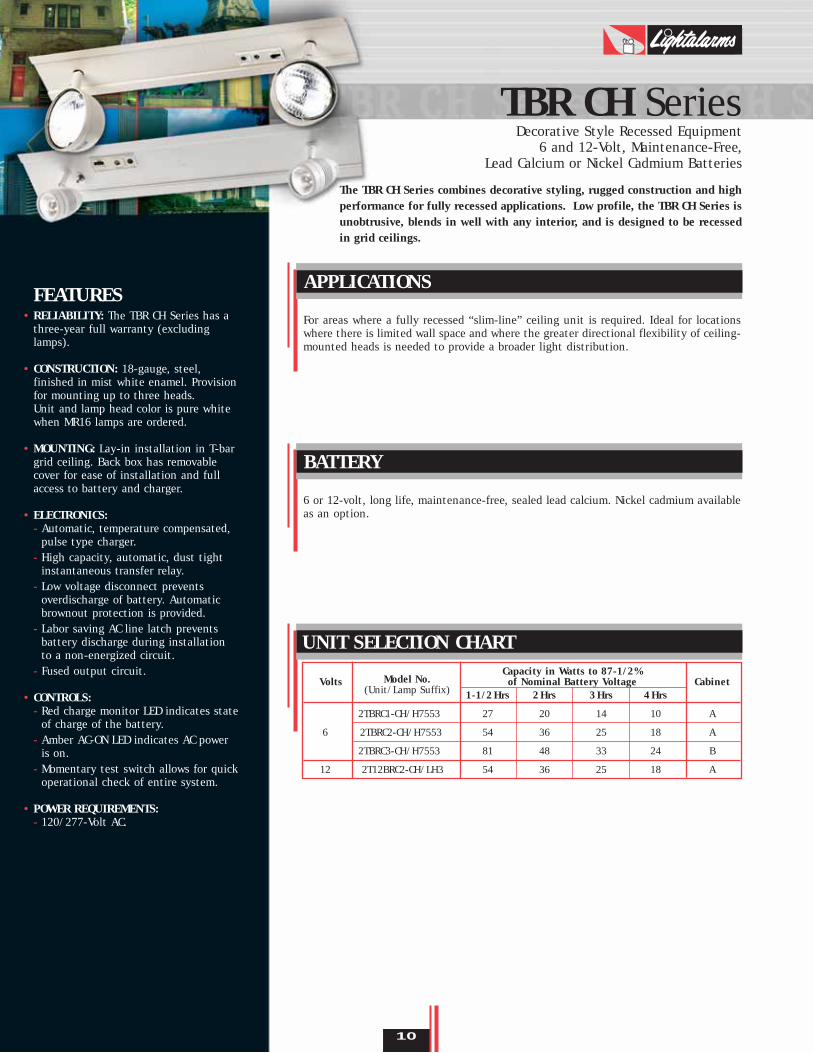
Decorative Style Recessed Equipment6 and 12-Volt, Maintenance-Free,
Lead Calcium or Nickel Cadmium Batteries
The TBR CH Series combines decorative styling, rugged construction and highperformance for fully recessed applications. Low profile, the TBR CH Series isunobtrusive, blends in well with any interior, and is designed to be recessedin grid ceilings.
TBR CH Series
For areas where a fully recessed “slim-line” ceiling unit is required. Ideal for locationswhere there is limited wall space and where the greater directional flexibility of ceiling-mounted heads is needed to provide a broader light distribution.
APPLICATIONS
6 or 12-volt, long life, maintenance-free, sealed lead calcium. Nickel cadmium availableas an option.
BATTERY
UNIT SELECTION CHART
10
Model No.Capacity in Watts to 87-1/2%
Volts(Unit/Lamp Suffix)
of Nominal Battery Voltage Cabinet1-1/2Hrs 2Hrs 3Hrs 4Hrs
2TBRC1-CH/H7553 27 20 14 10 A
6 2TBRC2-CH/H7553 54 36 25 18 A
2TBRC3-CH/H7553 81 48 33 24 B
12 2T12BRC2-CH/LH3 54 36 25 18 A

ORDERING FORMAT
TBR CH Series
DIMENSIONS
11
2 TBR C1 -CH /H7553 -M -ID
2................No. of Heads (0,1,2,3)
TBR............Series(TBR=6 VDC, T12BR=12 VDC)
C1..............Capacity Indicator(See Unit Selection Chart)
-CH ............City of Chicago Spec./H7553 ......Lamp Suffix*-M..............Standard Mist White Finish-ID ............Improved Diagnostics (See Options)
* See lamp chart on p. 22 for alternate lamps. Do not exceed unitrating in capacity or voltage.
Cabinet aA 3-1/4”B 5-5/8”
Black Housing and Heads (replace “M” by)..................-BVoltmeter................................................................-V*Time Delay (12 min.) ..............................................TD**Improved Diagnostics ..............................................-IDImproved Diagnostics, Non-Audible ......................-IDNANickel Cadmium Battery ..........................................-N
* Not available with ID/IDNA option.** Not required with ID/IDNA option.
OPTIONS (Add suffix to Model No.)
Remote Test Switch, Metal Faceplate ......................-RTS
ACCESSORIES (Order as separate item)
LAMP HEADS
All metal, ELF622 heads are standard and supplied with 6-volt or 12-volt, PAR36 12-watt lamps as specified. DR1130 heads are optionalon 12-volt units and may be 12-watt or 20-watt MR16 lamps.Example: 2T12BRC2-CH/1130-M12 12-Watt MR162T12BRC2-CH/1130-M20 20-Watt MR16
Unit and lamp head color is pure white when MR16 lamps areordered.
®
Listed

FEATURES• RELIABILITY: The MG CH Series comes
complete with a 3-year full warranty(excluding lamps).
• HOUSING: Constructed of 20 gauge steelwith an off-white, baked enamel finish.Hinged cabinet door for easy access.Furnished standard with two ELF622heads with one 12-watt lamp per head(see Unit Selection Chart). Unit andlamp head color is pure white whenMR16 lamps are ordered.
• MOUNTING: Conduit knockouts and rearkeyhole mounting slots are provided.
• ELECTRONICS: - Automatic, temperature compensated,
pulse type charger.- High capacity, automatic, dust-tight
instantaneous transfer relay.- Low voltage disconnect prevents
overdischarge of battery. Automaticbrownout protection is provided.
- Labor saving AC line latch preventsbattery discharge during installationto a non-energized circuit.
• CONTROLS:- Red charge monitor LED indicates state
of charge of the battery.- Orange AC-ON LED indicates AC power
is on.- Momentary test switch allows for quick
operational check of entire system.
• POWER REQUIREMENTS:- 120/277 Volt AC
Industrial/Commercial Unit Equipment, 6 and 12- Volt, Maintenance-Free,
Lead Calcium or Nickel Cadmium Battery
The MG CH Series is an excellent combination of economy, quality and versatility. Its compact, all-metal housing is offered in a wide variety of battery choices and wattages. The MG CH Series comes with our highly reliable pulse type charger. Improved Diagnostics are available as an option.
MG CH Series
Compact housing design meets most requirements for moderate loads. Reliable, economicunits for most commercial applications.
APPLICATION
12
UNIT SELECTION CHART
Model No. Capacity in Watts to 87-1/2%Volts (Unit/Lamp Suffix) of Nominal Battery Voltage
1-1/2Hrs 2Hrs 3Hrs 4Hrs
2MG27CH/LHK-M 27 18 14 106
2MG54-CH/LHK-M* 54 37 28 21
2M12G36-CH/LH3-M 36 25 20 1412
2M12G54-CH/LH3-M* 54 37 28 21
6 2MN25-CH/LHK-M 25 18 12 9
2M12N36-CH/LH3-M 36 21 15 1212
2M12N50-CH/LH3-M 50 36 25 18
12V, 12W Bi-Pin Halogen, ELF622-CH Heads12V, 20W, MR16, DR1130 Heads12V, 12W, MR16, DR1130 Heads
* Do not exceed unit rating in voltage or capacity.See lamp chart on page 22.
Sealed Maintenance-Free
Battery Types
Lead Calcium
Nickel Cadmium
CabinetSize
S
L
S
L
S
S
S

MG CH Series
13
Black Housing and Heads ........................................-BAmmeter or Voltmeter (choose only one) ........-A or –V *Disconnect Switch ................................................-DSImproved Diagnostics ............................................-ID **Improved Diagnostics, Non-Audible ....................-IDNATime Delay (12 minutes) ........................................-TD ***Tamper Proof ........................................................-TPFront Mounted Heads (for low ceilings) ..................-FM3-wire Cord & Plug ..............................................-3CP3-wire Cord & Plug (277V) ..............................-3CP-277
*Not available with ID/IDNA option.**Only available with Lead Calcium battery.***Not required when using the ID/IDNA option.
OPTIONS
Mounting Platform ..........................................MP-PQAWire Guard (S Cabinet)..........................................WG1Wire Guard (L Cabinet)..........................................WG2Wire Guard (Front Mounted Heads) ......................WG10Polycarbonate Vandal Resistant Shield (L Cabinet) ......CPSNEMA-4X Polycarbonate Vandal Resistant Shield (S Cabinet) ..............................CPS-4X
ACCESSORIES
ORDERING FORMAT
All metal, ELF622 heads are standard and suppliedwith 6 or 12-volt, 12-watt lamps as specified. DR1130heads are optional on 12-volt units and may be 12 or20-watts.Example:M12G36-CH/1130-M12 12-Watt MR16M12G36-CH/1130-M20 20-Watt MR16Unit and lamp head color is pure white when MR16lamps are ordered.
Note: Do not exceed unit rating in voltage or capacity.
LAMP HEADS
®
Listed
(Add suffix to Model No.) (Order as separate item)
2 MG 27 -CH /LHK -M -V
2................No. of Heads (0,1,2,3)
MG ............Series/DC Voltage(MG=6 VDC, M12G=12 VDC)
27..............Capacity Indicator(See Unit Selection Chart)
-CH ............City of Chicago Spec./LHK..........Lamp Suffix*-M..............StandardMist White Finish-V ..............Voltmeter (See Options)
* See lamp chart on p. 22 for alternate lamps. Do not exceedunit rating in capacity or voltage.
DIMENSIONS
Cabinet a b c dS 11-7/8”//8-3/4” 11” 3-1/2” 5-1/4”L 13”//9-7/8” 12-3/4” 4” 6-3/8”

FEATURES• RELIABILITY: The PG CH Series has a
three-year full warranty (excluding lamps).
• HOUSING: Heavy duty steel case withfront access panel and mist white enamelfinish.Unit and lamp head color is pure white when MR16 lamps are ordered.
• MOUNTING: Conduit knockouts and rearkeyhole mounting slots are provided.
• ELECTRONICS:- Automatic, temperature-compensated,
pulse-type charger.- High capacity, automatic, dust tight
instantaneous transfer relay.- Labor-saving AC line latch prevents
battery discharge during installation to a non-energized circuit.
- Low voltage disconnect prevents over discharge of battery. Automatic brownoutprotection is provided.
- Fused output circuits (PG2 CH, P12G1 CH).
• CONTROLS:- Red charger monitor LED indicates state
of charge of the battery.- Amber AC-ON LED indicates AC power
is on.- Momentary test switch allows for quick
operational check of entire system.
• POWER REQUIREMENTS:- 120/277-Volt AC, 0.25A, 30W (max.).
Industrial/Commercial Unit Equipment6 and 12-Volt, Maintenance-Free Lead Calcium Battery
The PG CH Series is a traditionally-styled, multi-purpose emergency lightingunit that offers reliability, versatility, performance and cost-efficiency in anaesthetically-pleasing design.
PG CH Series
Designed to meet requirements for moderate loads, the PG CH, P12G CH Series is a reliable, economical choice for most public areas.
APPLICATIONS
6 or 12-Volt, maintenance-free sealed lead calcium. Battery capacities meet the 90minute required run time or extended run times based on lamp load.
BATTERY
UNIT SELECTION CHART
14
Model No. Capacity in Watts to 87-1/2%Volts (Unit/Lamp Suffix) of Nominal Battery Voltage
1-1/2Hrs 2Hrs 3Hrs 4Hrs
2PG1-CH/H7553-M 27 20 14 106
2PG2-CH/H7553-M 54 36 27 18
12 2P12G1-CH/LH3-M 54 36 27 18

PG CH Series
Black Housing and Heads .......................................... -BVoltmeter ................................................................-V*Disconnect Switch .................................................. -DSImproved Diagnostics .............................................. -IDImproved Diagnostics , Non-Audible ...................... -IDNATime Delay ............................................................ -TD**Tamper Proof.......................................................... -TP3-Wire Cord and Plug ............................................ -3CP3-Wire Cord and Plug(277V)............................ -3CP-277
*Not available with ID/IDNA option. **Not required with the ID/IDNA option.
OPTIONS
Wire Guard ..........................................................WG2Mounting Platform ........................................ MP-PQA
ACCESSORIES
ORDERING FORMAT
All metal, ELF622 heads are standard and suppliedwith 6 or 12-volt, 12-watt lamps as specified. DR1130heads are optional on 12-volt units and may be 12 or20-watts.Example:2P12G1-CH/1130-M12 12-Watt MR162P12G1-CH/1130-M20 20-Watt MR16
Unit and lamp head color is pure white when MR16lamps are ordered.
LAMP HEADS
15
®
Listed
(Add suffix to Model No.) (Order as separate item)
2 PG 1 -CH /H7553 -M -ID
2................No. of Heads (0,1,2,3)
PG ............Series/DC Voltage(PG=6 VDC, P12G=12 VDC)
1................Capacity Indicator(See Unit Selection Chart)
-CH ............City of Chicago Spec./H7553 ......Lamp Suffix*-M..............StandardMist White Finish-ID ............Improved Diagnostics (See Options)
* See lamp chart on p. 22 for alternate lamps. Do not exceedunit rating in capacity or voltage.
DIMENSIONS

FEATURES• RELIABILITY: The PQ CH, P12Q CH
Series has a three-year full warranty(excluding lamps).
• HOUSING: Heavy duty steel case with front access panel has mist whiteenamel finish.
Unit and lamp head color is pure white when MR16 lamps are ordered.
• MOUNTING: Conduit knockouts and rear keyhole mounting slots are provided.
• ELECTRONICS:- Automatic, temperature compensated,
pulse type charger.
- High capacity, automatic, dust tight instantaneous transfer relay.
- Low voltage disconnect prevents overdischarge of battery. Automatic brownout protection is provided.
- Labor saving AC line latch prevents battery discharge during installation to a non-energized circuit.
- Fused output circuit.
• CONTROLS:- Red charge monitor LED indicates
state of charge of the battery.
- Amber AC-ON LED indicates AC power is on.
- Momentary test switch allows for quickoperational check of entire system.
• POWER REQUIREMENTS:- 120/277-Volt AC.
Industrial/Commercial Unit Equipment, 6 and 12-Volt,Maintenance-Free, Lead Calcium Battery
The PQ CH, P12Q CH Series is a traditionally styled battery unit with highcapacity, maintenance-free batteries — the perfect combination of functionand performance for most industrial and commercial environments.
PQ CH Series
16
Industrial, institutional and commercial environments where remote capability orextended operating times are required.
APPLICATIONS
6 or 12-volt, maintenance-free sealed lead calcium.
BATTERY
UNIT SELECTION CHART
VoltsModel No. Capacity in Watts to 87-1/2%
Cabinet(Unit/Lamp Suffix)of Nominal Battery Voltage
1-1/2Hrs 2Hrs 3Hrs 4Hrs
2PQ2-CH/H7553-M 100 75 50 36 B6
2PQ3-CH/H7553-M 200 150 100 72 C
2P12Q1-CH/LH3-M 100 75 50 36 B12
2P12Q2-CH/LH3-M 200 150 107 85 C

PQ CH Series
DIMENSIONS
17
2 PQ 2 -CH /H7553 -M -V
2................No. of Heads (0,1,2,3)PQ..............Series/DC Voltage
(PQ = 6 VDC, P12Q = 12 VDC)2................Capacity Indicator
(See Unit Selection Chart)-CH ............City of Chicago Spec./H7553 ......Lamp Suffix*-M..............StandardMist White Finish-V ..............Voltmeter (See Options)
* See lamp chart on p.22 for alternate lamps. Do not exceed unit rating in capacity or voltage.
Black Housing and Heads........................................ -BVoltmeter.............................................................. -V*Ammeter .............................................................. -A*Improved Diagnostics ............................................ -IDImproved Diagnostics, Non-Audible ...................... -IDNATime delay (12 min.) ............................................ -TD***Tamper Proof ...................................................... -TP3-Wire Cord & Plug ............................................ -3CP3-Wire Cord & Plug (277V)............................ -3CP-277
Available with either voltmeter or ammeter - not both.*Voltmeter and ammeter not available with the ID/IDNA option.***Not required with ID/IDNA option.
OPTIONS
Wire Guard ........................................................ WG3Mounting Platform.......................................... MP-PQB
ACCESSORIES
ORDERING FORMAT
All metal, ELF622 heads are standard and supplied with 6 or 12-volt, 12 watt lamps as specified. DR1130 heads areoptional on 12-volt units and may be 12, 20 or 35 watts.Example:2P12Q1-CH/1130-M12 12-Watt MR162P12Q1-CH/1130-M20 20-Watt MR162P12Q1-CH/1130-M35 35-Watt MR16
Unit and lamp head color is pure white when MR16lamps are ordered.
Note: Do not exceed unit rating in voltage or capacity.
LAMP HEADS
(Add suffix to Model No.)
®
Listed
(Order as separate item)
Cabinet a b c dB 17-1/8”//14” 16-1/8” 5-1/2” 10-1/2”C 19”//15-7/8” 16-1/2” 7-1/2” 12-1/4”

FEATURES• RELIABILITY: The PN CH, P12N CH
Series has a three-year full warranty(excluding lamps).
• HOUSING: Heavy duty steel case withfront access panel and mist white enamel finish.Unit and lamp head color is pure white when MR16 lamps are ordered.
• MOUNTING: Conduit knockouts and rearkeyhole mounting slots are provided.
• ELECTRONICS:- Automatic, temperature-compensated,
pulse-type charger.- High capacity, automatic, dust-tight
instantaneous transfer relay.- Labor-saving AC line latch prevents
battery discharge during installation to a non-energized circuit.
- Automatic brownout protectionis provided.
- Fused output circuit.
• CONTROLS:- Red charger monitor LED indicates
state of charge of the battery.- Amber AC-ON LED indicates AC
power is on.- Momentary test switch allows for quick
operational check of entire system.
• POWER REQUIREMENTS:- 120/277-Volt AC.
Industrial/Commercial Unit Equipment 6 or 12-Volt,Maintenance-Free, Nickel Cadmium Battery
The PN CH, P12N CH Series is a traditionally styled, high performance unit.Long-life nickel cadmium batteries are maintenance-free and designed specifically for environments where lighting units may be exposed to fluctuations in temperature.
PN CH, P12N CH Series
Recommended where the long-life andmaintenance-free features of sealed nickelcadmium batteries are required. Nickelcadmium batteries outperform lead acidbatteries in dramatic ambient temperaturefluctuations.
APPLICATIONS
6 or 12-volt, long life, maintenance-freesealed nickel cadmium.
BATTERY
Black Housing and Heads (replace “M” by) -BVoltmeter.......................................... -V*Ammeter .......................................... -A*Disconnect Switch............................ -DSImproved Diagnostics, Non-Audible .. -IDNATime Delay (12 min.) ........................-TD**Tamper Proof .................................. -TP3-Wire Cord and Plug...................... -3CP3-Wire Cord and Plug (277V) .... -3CP-277*Not available with IDNA.**Not required when using the IDNA option.
OPTIONS
Wire Guard (A Cabinet) ..............WG2Wire Guard (B Cabinet) ..............WG3Mounting Platform .............. MP-PQA
ACCESSORIES
UNIT SELECTION CHART
ORDERING FORMATAll metal, ELF622 heads are standard andsupplied with 6 or 12-volt, 12-watt lamps as specified. DR1130 heads are optional on 12-volt units and may be 12, 20 or 35-watts.Example:2P12N1-CH/1130-M12 12-Watt MR162P12N1-CH/1130-M20 20-Watt MR162P12N1-CH/1130-M35 35-Watt MR16Unit and lamp head color is pure whitewhen MR16 lamps are ordered.
Note: Do not exceed unit rating in voltage or capacity.
LAMP HEADS
DIMENSIONS
(Add suffix to Model No.)
(Order as separate item)
Model No. Capacity in Watts to 87-1/2%Volts (Unit/ of Nominal Battery Voltage
Lamp Suffix) 1-1/2Hrs 2Hrs 3Hrs 4Hrs
2PN1-CH/LH3-M 25 20 14 106
2P12N1-CH/LH3-M 50 36 25 18
12 2P12N2-CH/LHK-M 72 60 50 36
2 P12N 2 -CH /LH3 -M -V
2 ............No. of Heads (0,1,2,3)P12N ......Series/DC Voltage
(PN = 6 VDC, P12N = 12 VDC)2 ............Capacity Indicator
(See Unit Selection Chart)-CH ........City of Chicago Spec./LH3 ......Lamp Suffix*-M ..........Standard Mist White Finish-V ..........Voltmeter (See Options)
* See lamp chart on p.22 alternate lamps. Do notexceed unit rating in capacity or voltage.
18
Cabinet a b c dA 17-1/8”//14” 13” 3-5/8” 10-1/2”B 17-1/8”//14” 16-1/8” 5-1/2” 10-1/2”
A
A
B
Cabinet
®
Listed

SN CH Series
19
Industrial/Commercial Unit Equipment 6-Volt, Nickel Cadmium Battery
The SN CH Series offers a wide variety of capacities utilizing highly-reliable wet Nickel Cadmium batteries. Able to withstand temperature fluctuations and provideextended illumination times, these units can stand alone and also drive remote emergency lights.
Excellent high capacity units ideal whereextended unit run times may be required,and/or remote fixtures will be connected.Unit offers special advantages of the long-life nickel cadmium battery includingexcellent recharging capability, and superiorperformance over extended temperatureranges.
APPLICATIONS
6-volt high performance wet NickelCadmium battery in translucent plasticcells with expected life of 13 years.
BATTERY
Voltmeter.................................... -VAmmeter .................................... -ADisconnect Switch...................... -DSTime Delay (12 min.).................. -TDThermal Jacket (120V) .............. -H1Thermal Jacket (277V) .............. -H23-Wire Cord & Plug .................. -3CP3-Wire Cord & Plug (277V).. -3CP-277
OPTIONS
Wire Guard .............................. WG3Mounting Platform .................. MP-A
ACCESSORIES
ORDERING FORMAT All metal, ELF622 heads standard with 6-volt, 12-watt lamps. See lamp data onp.22 for alternate lamps.
Note: Do not exceed unit rating in voltage orcapacity.
LAMP HEADS
(Add suffix to Model No.)
FEATURES• RELIABILITY: The SN CH Series has a
three-year full warranty (excludinglamps).
• HOUSING: Heavy duty steel case with front access panel and gray enamel finish.
• MOUNTING: Conduit knockouts and rearkeyhole mounting slots are provided.Mounting platform or bracket available.
• ELECTRONICS:- Automatic, temperature-compensated,
pulse-type charger.- High capacity, automatic, dust-tight
instantaneous transfer relay.- Labor-saving AC line latch prevents
battery discharge during installation to a non-energized circuit.
- Automatic brownout protectionis provided.
- Two separately fused output circuits.
• CONTROLS:- Red charger monitor LED indicates
state of charge of the battery.- Amber AC-ON LED indicates AC power
is on.- Momentary test switch allows for quick
operational check of entire system.
• POWER REQUIREMENTS:- 120/277-Volt AC.
UNIT SELECTION CHARTDIMENSIONS
2 SN 4 -CH/H7553 -G -V
2 ............No. of Heads (0,1,2,3)
SN ..........Series4 ............Capacity Indicator
(See Unit Selection Chart)
-CH ........City of Chicago Spec./H7553 ..Lamp Suffix*-G ..........StandardGray Finish-V ..........Voltmeter (See Options)
* See lamp chart on p.22 for alternate lamps.Do not exceed unit rating in capacity or voltage.
Model No.Capacity in Watts to 87-1/2%
Volts Cabinet (Unit/Lamp Suffix)of Nominal Battery Voltage
1-1/2Hrs. 2Hrs. 3Hrs. 4Hrs.C 2SN2-CH/H7553-G 50 45 25 18C 2SN3-CH/H7553-G 70 60 35 25
6 C 2SN4-CH/H7553-G 100 80 50 35C 2SN6-CH/H7553-G 130 105 70 50C 2SN7-CH/H7553-G 160 130 80 60
(Order as separate item)
®
Listed

FEATURES• RELIABILITY: The DR1130-CH Series
come complete with a 3-year warranty(excluding lamps).
• UNIT DATA: Die-cast aluminum construction withresistant epoxy powder-coated finish.Available in 1, 2 or 3 head configurations in white or black. Light source is MR16 halogen lamps. In 12, 20, 35 or 50-watt.
Unit Heads and Matching RemoteEmergency Lighting Fixtures
For interiors where aesthetics are a priority, the DR1130-CH Series combinescontemporary styling with the ultra efficiency of MR16 halogen lamps.
DR1130-CH Series
DIMENSIONS
®
Listed
LAMP DATA
Lamp Catalog Center Beamtype Suffix Voltage Watts Candle Power
M12 12 12 400
M20 12 20 600
M35 12 35 1500
M50 12 50 2200
MR16
Model
DR1130 = One HeadDR2130 = Two HeadsDR3130 = Three Heads
Color
WH = WhiteBK = Black
Wattage
-12W = 12-Watt-20W = 20-Watt-35W = 35-Watt-50W = 50-Watt
City of ChicagoApproved
-CH
ORDERING INFORMATIONExample: DR1130WH-20W-CH
For replacement part number, consult Lamp Chart on p.22.
20
DR1130CH
DR2130CH DR3130CH
DR1130-CH
DR2130-CH DR3130-CH

Unit Heads and Matching RemoteEmergency Lighting Fixtures
A multi-purpose, surface-type remote fixture, the ELF622-CH Series is ideallysuited for most commercial applications.
ELF622-CH Series
DIMENSIONS
LAMP DATA
FEATURES• RELIABILITY: The ELF622-CH Series
come complete with a 3-year warranty(excluding lamps).
• UNIT DATA:All metal construction remote head fixture with fully adjustable swivel.Available as a single, double or triple head fixture. Standard finish is chrome.Off-white or black available as anoption. PAR36 sealed beam, PAR36sealed beam halogen, and Bi-Pin halogen lamps are available.
®
Listed
Lamp Type Catalog Suffix Voltage Watts Lumen
LHK 6 12 240
LH8 6 20 402
LH3 12 12 12 300
LH8 12 12 20 314
H7553 6 12 227
H7554 6 20 382
H7557 12 12 262
H7616 12 37 756
4510 6 25 385
4515 6 30 460
4446 12 25 395
4406 12 35 460
Bi-PinHalogen
PAR36 SealedBeam Halogen
PAR36Sealed Beam
ORDERING INFORMATIONExample: ELF622-CH/LHK-M6 or ELF622-CH/H7553-M
Model
ELF622 = One HeadELF622D = Two HeadsELF622T = Three Heads
City of ChicagoApproved
-CH
Lamp Type
/LHK = 6V, 12W/H7553 = 6V, 12W/LH3 = 12V, 12W
Color
Blank = Chrome-M = Mist White-BK = Black
Voltage
Blank = sealed beam6 = 6-Volt12 = 12-Volt
For replacement part number, consult Lamp Chart on p.22.
21
ELF622-CH
ELF622D-CH
ELF622T-CH

Lamp Data
22
Lamp Type
Bi-Pin Halogen
PAR36 Sealed Beam
Halogen
PAR36 Sealed Beam
MR16
Catalogue Voltage Watts Lumens ReplacementSuffix Parts
LHK 6 12 420 580.0011
LH8 6 20 402 580.0022
LH3 12 12 12 300 580.0015
LH8 12 12 20 314 580.0027
H7553 6 12 227 550.0089
H7554 6 20 382 550.0021
H7557 12 12 262 550.0025
H7616 12 37 756 550.0047
4510 6 25 385 550.0017
4515 6 30 460 550.0035
4446 12 25 395 550.0023
4406 12 35 460 550.0032
M12 12 12 400 580.0080
M20 12 20 600 580.0075
M35 12 35 1500 580.0083
M50 12 50 2200 580.0076
Center BeamCandle Power
BI-PIN Halogen Lamps
Sealed Beam Lamps
Halogen
PAR36
T-2 3/4
MR16

Popular Options
23
Lightalarms life safety equipment is available with a range of options that can beadded to enhance performance, simplify testing or adapt equipment for use in specific environments. Please refer to individual product pages to verify availabilityof individual options on specific equipment.
VoltmeterOption provides a visual indication, in the test mode, of the unit’s battery voltage. The good/checkmeter face allows maintenance personnel to recognize charger and battery function.Add Suffix: -V
AmmeterOption provides an indication of charge current when the unit is in the equalize mode.This verifies charger capability and the current acceptance of the battery.Add Suffix: -A
Dual CircuitOption provides two A.C. input circuits to permit 2 separate A.C. sources to energize the sign.Available in 120/120VAC or 277/277VAC.Add Suffix: -2
Tamper ProofTamper proof screws may be used on certain units to avoid unauthorized entry to circuitry orvandalism. Add Suffix: -TP
Disconnect SwitchOption will disconnect lamp load when area is not in use during prolonged power failure. Theswitch may also be used to reactivate emergency power to remote or built in heads.Add Suffix: -DS
Time DelayOption is designed to be used in areas where mercury vapor of HID type lamps are used for normallighting. As these lamps require several minutes to re-strike and to produce their nominal lightingoutput, it is necessary to also hold the emergency lighting on for this period, even after the AC utility has been restored. A time delay unit can be helpful in areas where it is difficult to directlyaccess an emergency lighting unit’s test switch. The power to the unit can be briefly switched offand on at the breaker panel, and the maintenance person can then return to the unit and observea timed emergency operation.Add Suffix: -TD
Remote Test Switch A hardwired push button test switch connected in series with the AC emergency line facilitatestesting emergency lighting units that are not easily accessible.Add Suffix: -RTS
Damp Location Option for environments that are subject to moderate amounts of moisture (humidity), and a temperature range between 10 and 40 degrees C. Example: partially protected exterior areas suchas canopies, stairwells, etc.Add Suffix: -DL
Thermal Jacket Option to be used in areas where temperature may drop below 0ºC. The thermostat will activatethe heating pad at 0ºC and will cut off at 16ºC. The heating pad is rated at 50 watts. Contactfactory for temperature limitations.Add Suffix: -H1 (120V) -H2 (277 V)
Self-Test/Diagnostic Feature (for exit signs)Option is designed to continuously monitor the charger assembly, battery and LED assembly current.If a fault is indicated the external service required indicator will illuminate. The diagnostic/self testwill self test for 30 seconds every 30 days, 30 minutes every 60 days and 90 minutes annually. MeetsNFPA 101 Life Safety Code requirements for periodic testing.Add Suffix: -D
Improved Diagnostics/Improved Diagnostics Non-audible (ID/IDNA, for battery units)See page 26.

Accessories
24
Wire Guard 5Catalog Number: WG5
Wire Guard 6Catalog Number: WG6
Wire Guard 10Catalog Number: WG10
13"
18"
16"
14"
15"
13"
14"
5 1/2" 15 1/4"
3 1/2"
20"
12"
15"23"
12"
WireGuards
VandalResistant
Covers
Wire Guard 1Catalog Number: WG1
Wire Guard 2Catalog Number: WG2
Wire Guard 3Catalog Number: WG3
18"
6"
20"17 1/2"
16 1/2"
14"
13 3/4" 16"
12"
5"
20" 19"
13"
Wire Guard 12Catalog Number: WG12 13 1/2"
4 1/2"
10 1/4" 15"
9"
Wire Guard 4Catalog Number: WG4
30"
9"
24"
Vandal Resistant CoverApplication: MG CH SeriesCatalog Number: CPS or CPS-4X (NEMA-4X)

Accessories
25
MountingPlatforms
MountingBrackets
• 14 gauge steel
• Corrosion resistant undercoat
• Oven baked hammertone finish
• 1/2" retaining lip on three sides
• Keyhole slots for easy mounting
• 16 gauge steel
• Corrosion resistant undercoat
• Oven baked hammertone finish
• Supplied with rubber stand-offs for unit and machine screws tosecure unit to bracket
Model Dimensions (inches)
A B C D
MB-A 10 7 1/2 2 3/16 7
Model Dimensions (inches)
A B C D E F G
MP-PQB & MP-A 17 7 3/4 12 1/4 16 3/45/16
5/8
MP-PQA 16 3/8 5 3/4 10 1/4 12 1/2 7/8
1/83/8
MP-PQB + MP-A MP-PQA

Improved Diagnostics
26
By incorporating our most popular standard diagnostics features with a powerful 8-bitmicrocontroller, our new Improved Diagnostics system assures unsurpassed reliability inone, totally contained system. In the event of an equipment malfunction, the improveddiagnostics system produces an audible warning in the form of an intermittent beep and the LED indicator associated with the fault will illuminate continuously. When theproblem is acknowledged by depressing the alarm/silence/test button, the alarm is silencedand the LED indicator changes to a flashing mode until the problem is corrected.
• Continually monitors system parameters
• Incorporates state-of-the-art microcontroller technology
• ID includes audio and visual service alarms
• IDNA non-audible version for visual service alarms only
• Self-testing in accordance with NFPA101, Life Safety Code
FEATURES• BATTERY FAILURE:
(Red) Illuminates if the battery is shorted or battery voltage drops below preset value. Will also detect incorrect battery (ie. 6VDC vs. 12VDC)
• BATTERY DISCONNECT: (Red) Illuminates if the battery circuit is open.
• CHARGER FAILURE: (Red) Illuminates when charger is not functioning properly by monitoring the charger current.
• LAMP FAILURE:(Red) Illuminates when one or more emergency lamps burn. Also monitors remote lamps.
• SERVICE ALARM: (Red) Illuminates when a fault is detected that requires a qualified service technician.
• AC ON: (Green) Lit when line voltage is present.
• CHARGER ON: (Amber) Illuminates when charger is recharging the battery.
• ALARM ON:Button is used to acknowledge and silence alarms. Also functions as a manual test switch to simulate a power failure.
• SELF TESTING:Unit tests itself every thirty days for one minute, thirty minutes on the sixth month and ninety minutes annually.
• TO ORDER FOR COMPATIBLE UNIT:Add suffix -ID to model numberAdd suffix -IDNA (for non-audible circuit) to model number.

Wiring Size Guide
27
Determining Wire SizeThe following information is provided to assist in designing proper emergency lighting systems effectively and economically by using a code-compliant wire size for load circuits.When remote lighting fixtures and/or exit signs are connected to emergency lighting units,circuit runs must be of sufficient size to maintain a proper operating voltage to all lamps.The National Electrical Code limits voltage to drop to a maximum of 5% of nominal. Thetable below gives the maximum length or wire run based on systems voltage, wire gaugeand total wattage on the run. To determine the maximum length of a wire run not listed,divide the value of the load in watts into the constant listed at the bottom of each row.Example, the maximum wire run for #10 wire on a 12 volt system, with a 54 watt load, is3397 ÷ 54 or, or 62 feet.
Conversely, to determine the maximum load on a run of known length, divide the lengthinto the constant. Example, a 36 foot run of #12 wire on a 6 volt systems can be loaded to, 534 ÷ 36, or 14 watts; on #10 wire, 23 watts.
Longer Wire RunsThe wiring distances give the maximum length of a battery circuit,assuming that the entire load is concentrated at the end of the circuit. If loads are uniformly spaced along the circuit path (equalwatts, equal distances), the lengths in the table may be increased,based on number of fixtures on a given circuit, by means of the chartand formula below.
Number of Fixtures 2 3 4 5 6 N
Multiply Feet By 1.33 1.5 1.6 1.67 1.7 12n/(n+1)
For example, a 36 foot long, 6 volt circuit has (3) 9 watt headsspaced 12 feet apart. According to the wire run table, # 8 wire mustbe used (at 50 feet for a 5% voltage drop.) but, by multiplying the31 feet for #10 wire by 1.5, a 461/2 foot wire run is acceptable, so#10 wire may be used and still meet the 5% voltage drop limitation.
Note: According to the National Electrical Code, Article 720-Y, thesmallest permissible wire size for systems under 50 volts is the #12wire gage.
#128966595344332922211917141211111075——————534
WIRING DISTANCE IN FEET (Maximum Voltage Drop 5%)
#1014110694847053473533312823201817161185—————849
#635726823821417813411989857971595147444228211410875—
2148
#1235626723721317813311889857971595047444228211410875—
2137
#10566424377339283212188141135125113948075706745332216131186
3397
#89006756005404503373002252162001801501281201121087254362721181310
5403
#61431107395485971553647735734331828623820419017817111485574234282117
8590
#4+
1707151713661138853758569546505455379325303284273182136916854453427
13660
#121425106894985471253447435634131628423720318917817011385564234282117
8548
#10+
1698150913581132849754566543503452377323301283271181135906754453327
13588
#8++++
18011350120090086480072060051448045043228821614410886725443
21613
Total watts onwire run
6891012161824252730364245485075100150200250300400500
Constant
6 volt wire size 12 volt wire size 24 volt wire size#822516815013511284755654504537323028271813965———
1350
#6++++++
190914311374127211459548187637156874583432291711371148568
34363

Life Safety Code
28
SECTION 7.8 ILLUMINATION OF MEANS OF EGRESS7.8.1 General.
7.8.1.1* Illumination of means of egress shall be providedin accordance with section 7.8 for every building andstructure where required in Chapters 11 through 42. Forthe purposes of this requirement, exit access shall includeonly designated stairs, aisles, corridors, ramps, escalators,and passageways leading to an exit. For the purposes of this requirement, exit discharge shall include only designated stairs, aisles, corridors, ramps, escalators,walkways, and exit passageways leading to a public way.
7.8.1.2 Illumination of means of egress shall be continuousduring the time that the conditions of occupancy requirethat the means of egress be available for use. Artificial lighting shall be employed at such locations and for suchperiods of time as required to maintain the illumination tothe minimum criteria values herein specified.
Exception: Automatic, motion sensor-type lightingswitches shall be permitted within the means of egress, provided that switch controllers are equipped for fail-safeoperation, illumination timers are set for a minimum 15min duration, and the motion sensor is activated by anyoccupant movement in the area by the lighting units.
7.8.1.3* The floors and other walking surfaces within anexit and within the portions of the exit access and exitdischarge designated by 7.8.1.1 shall be illuminated tovalues of not less than 1 footcandle (10 Ix) measured atthe floor.
Exception No.1: In assembly occupancies, the illuminationof the floors of exit access shall be not less than 0.2 foot-candle (2 lx) during periods of performances or projectionsinvolving directed light.
Exception No.2*: This requirement shall not apply whereoperations or processes require low lighting levels.
7.8.1.4* Required illumination shall be arranged so thatthe failure of any single lighting unit does not result inan illumination level of less than 0.2 footcandle (2 lux)in any designated area.
7.8.1.5 The equipment or units installed to meet therequirements of Section 7.10 also shall be permitted to servethe function of illumination of means of egress, providedthat all requirements of section 7.8 for such illuminationare met.
7.8.2 Sources of Illumination.
7.8.2.1 Illumination of means of egress shall be from asource of considered reliable by the authority havingjurisdiction.
7.8.2.2 Battery-operated electric lights and other typesof portable lamps or lanterns shall not be used for primaryillumination of means of egress. Battery-operated electriclights shall be permitted to be used as an emergencysource to the extent permitted under Section 7.9
SECTION 7.9 EMERGENCY LIGHTING7.9.1 General.
7.9.1.1* Emergency lighting facilities for means of egressshall be provided in accordance with this section 7.9 forthe following: (1) Buildings or structures where requiredin Chapters 11 through 42. (2) Underground and windowlessstructures as addressed in section 11.7. (3) High-risebuildings as required by other sections of this code. (4) Doors equipped with delayed egress locks. (5) The stair shaft and vestibule of smokeproof enclosures which shall be permitted to include a standby generatorthat is installed for the smokeproof enclosure mechanical ventilation equipment and used for the stair shaft andvestibule emergency lighting power supply.For the purposes of this requirement, exit access shallinclude only designated stairs, aisles, corridors, ramps, escalators, and passageways leading to an exit. For the purposes of this requirement, exit discharge shall includeonly designated stairs, ramps, aisles, walkways, and escalators leading to a public way.
7.9.1.2 Where maintenance of illumination depends onchanging from one energy source to another, a delay of notmore than 10 seconds shall be permitted.
7.9.2 Performance of System.
7.9.2.1* Emergency illumination shall be provided for notless than 1 1/2 hours in the event of failure of normallighting. Emergency lighting facilities shall be arranged toprovide initial illumination that is not less than an averageof 1 footcandle (10 Ix) and, at any point, not less than 0.1footcandle (1 Ix) measured along the path of egress at floorlevel. Illumination levels shall be permitted to decline to notless than an average of 0.6 footcandle (6 Ix) and, at anypoint, not less than of 0.06 footcandle (0.6 Ix) at the end ofthe 1 1/2 hours. A maximum-to-minimum illuminationuniformity ratio of 40 to 1 shall not be exceeded.
7.9.2.2* The emergency lighting system shall be arrangedto provide the required illumination automatically in theevent of any of the following: (1) Interruption of normallighting such as any failure of public utility or other outsideelectrical power supply. (2) Opening of a circuit breaker orfuse. (3) Manual act(s), including accidental opening of aswitch controlling normal lighting facilities.
7.9.2.3 Emergency generators providing power to emergencylighting systems shall be installed, tested, and maintainedin accordance with NFPA 110, Standard for Emergency andStandby Power Systems. Stored electrical energy systemswhere required in this Code shall be installed and tested inaccordance with NFPA 111, Standard on Stored ElectricalEnergy Emergency and Standby Power Systems.
7.9.2.4* Battery-operated emergency lights shall useonly reliable types of rechargeable batteries providedwith suitable facilities for maintaining them in properlycharged condition. Batteries used in such lights or unitsshall be approved for their intended use and shall complywith NFPA 70, National Electrical Code®.
7.9.2.5 The emergency lighting system shall be eithercontinuously in operation or shall be capable of repeatedautomatic operation without manual intervention.
7.9.3 Periodic Testing of Emergency LightingEquipment. A functional test shall be conducted on everyrequired emergency lighting system at 30-day intervalsfor not less than 30 sec. An annual test shall be con-ducted for a 1-1/2 hour duration. Equipment shall befully operational for the duration of the test. Writtenrecords of visual inspections and tests shall be kept by theowner for inspection by the authority having jurisdiction.
Exception: Self-testing/self-diagnostic, battery-operatedemergency lighting equipment that automatically performsa a test of not less than 30 sec. and diagnostic routine notless than once every 30-days and indicates failure be statusindicator shall be exempt from the 30-day functional test,provided that a visual inspection is performed at 30-dayintervals.

Life Safety Code (cont’d)
29
SECTION 7.10 MARKING OF MEANS OF EGRESS7.10.1 General.
7.10.1.1 Where Required. Means of egress shall bemarked in accordance with section 7.10 where requiredby Chapters 11 through 42.
7.10.1.2* Exits. Exits, other than main exterior exitdoors that obviously and clearly are identifiable as exits,shall be marked by an approved sign readily visible fromany direction of exit access.
7.10.1.3 Exit Stair Door Tactile Signage. Tactile signageshall be located at each door into an exit stair enclosure,and such signage shall read as follows:
EXITSignage shall comply with CABO/ANSI A117.1, AmericanNational Standard for Accessible and Usable Buildings andFacilities, shall be installed adjacent to the latch side ofthe door 60 in. (152 cm) above the finished floor to thecenterline of the sign.
Exception: This requirement shall not apply to existingbuildings, provided the occupancy classification does notchange.
7.10.1.4* Exit Access. Access to exits shall be markedby approved, readily visible signs in all cases where theexit or way to reach it is not readily apparent to theoccupants. Sign placement shall be such that no point inthe exit access corridor is in access of 100 ft (30 m) fromthe nearest externally illuminated sign and is not in accessof the marked rating for internally illuminated signs.
Exception: Signs in exit access corridors in existingbuildings shall not be required to meet the placementdistance requirements.
7.10.1.5* Floor Proximity Exit Signs. Where floorproximity exit signs are required by Chapters 11 through42, signs shall be placed near the floor level in additionto those signs required for doors or corridors. Thesesigns shall be illuminated in accordance with 7.10.5.Externally illuminated signs shall be sized and inaccordance with 7.10.6.1. The bottom of the sign shallbe not less than 6 in. (15.2 cm) but not more than 8 in.(20.3 cm) above the floor. For exit doors, the sign shallbe mounted on the door or adjacent to the door with theclosest edge of the sign within 4 in. (10.2 cm) of thedoor frame.
7.10.1.6* Floor Proximity Egress Path Marking.Where floor proximity egress path marking is required inChapters 11 through 42, a listed and approved floorproximity egress path marking system that is internallyilluminated shall be installed within 8 in. (20.3 cm) ofthe floor. The system shall provide a visible delineationof the path of travel along the designated exit access andshall be essentially continuous, except as interrupted bydoorways, hallways, corridors, or other such architecturalfeatures. The system shall operate continuously or atany time the building fire alarm system is activated. Theactivation, duration, and continuity of operation of thesystem shall be in accordance with 7.9.2.
7.10.1.7* Visibility. Every sign required by Section7.10 shall be located and of such size, distinctive color,and design that it is readily visible and shall providecontrast with decorations, interior finish, or other signs.No decorations, furnishings, or equipment that impairsvisibility of an exit sign shall be permitted. No brightlyilluminated sign (for other than exit purposes), display,or object in or near the line of vision of the required exitsign that could detract attention from the exit sign shallbe permitted.
7.10.2* Directional Signs. A sign complying with7.10.3 with a directional indicator showing the directionof travel shall be placed in every location where the direc-tion of travel to reach the nearest exit is not apparent.
7.10.3* Sign Legend. Sign required by 7.10.1 and7.10.2 shall have the word EXIT or other appropriatewording in plainly legible letters.
7.10.4* Power Source. Where emergency lighting facilitiesare required by the applicable provisions of Chapters 11through 42 for individual occupancies, the signs, otherthan approved self-luminous signs, shall be illuminatedby the emergency lighting facilities. The level of illumi-nation of the exit sign shall be in accordance with7.10.6.3 or 7.10.7 for the required emergency lightingduration as specified in 7.9.2.1, However, the level ofillumination shall be permitted to decline to 60 percentat the end of the emergency lighting duration.
7.10.5 Illumination of Signs.
7.10.5.1* General. Every sign required by 7.10.1.2 or7.10.1.4, other than where operations or processesrequire low lighting levels, shall be suitably illuminatedby a reliable light source. Externally and internallyilluminated signs shall be legible in both the normal endemergency lighting mode.
7.10.5.2* Continuous Illumination. Every signrequired to be illuminated by 7.10.6.3 and 7.10.7 shallbe continuously illuminated as required under theprovisions of section 7.8.Exception:* Illumination for signs shall be permitted toflash on an and off upon activation of the five alarm systems.
7.10.6 Externally Illuminated Signs.
7.10.6.1* Size of Signs. Externally illuminated signsrequired by 7.10.1 and 7.10.2, other than approvedexisting signs, shall have the word EXIT or other appro-priate wording in plainly legible letters not less than 3/4in. (1.9 cm) wide. The word EXIT shall have letters of awidth not less than 2 in. (5 cm), except the letter 1, andthe minimum spacing between letters shall be not lessthan 3/8 in. (1 cm). Signs larger than the minimumestablished in this paragraph shall have letter widths,strokes, and spacing in proportion to their height.Exception No. 1: This requirement shall not apply to existingsigns having the required wording in plainly legible lettersnot less than 4 in. (10.2 cm) high. Exception No. 2: This requirement shall not apply tomarking required by 7.10.1.3 and 7.10.1.5.
7.10.6.2* Size and Location of Directional Indicator.The directional indicator shall be located outside of theEXIT legend, not less than 3/8 in. (1 cm) from any letter.The directional indicator shall be of a chevron type asshown in Figure 7.10.6.2. The directional indicator shallbe identifiable as a directional indicator at a distance of40 ft (12.2 m). A directional indicator larger than theminimum established in this paragraph shall be propor-tionately increased in height, width, and stroke. Thedirectional indicator shall be located at the end of thesign for the direction indicated.Exception: This requirement shall not apply to approvedexisting signs.

Life Safety Code (cont’d)
30
Figure 7.10.6.2 Chevron type indicator.
7.10.6.3* Level of Illumination. Externally illuminated signs shall be illuminated by not less than 5ft-candles (54 lux)at the illuminated surface and shall have a contrast ratio of not less than 0.5.
7.10.7 Internally Illuminated Signs.
7.10.7.1 Listing. Internally illuminated signs, other than approved existing signs, or existing signs, or existing signshaving the required wording in legible letters not less than 4 in. (10.2 cm) high, shall be listed in accordance with UL 924,Standard for Safety Emergency Lighting and Power Equipment.Exception: This requirement shall not apply to signs that are in accordance with 7.10.1.3 and 7.10.1.5.
7.10.7.2 Photoluminescent Signs. The face of a photoluminescent sign shall be continually illuminated while thebuilding is occupied. The illumination levels on the face of the face of the photoluminescent sign shall be in accor-dance with its listing. The charging illumination shall be a reliable light source as determined by the authority havingjurisdiction. The charging light source shall be of a type specified in the product markings.7.10.8 Special Signs.
7.10.8.1 No Exit. Any door, passage, or stairway that is neither an exit nor a way of exit access and that is locatedor arranged so that it is likely to be mistaken for an exit shall be identified by a sign that reads as follows.
NO EXITSuch sign shall have the word NO in letters 2 in. (5 cm) high with a stroke width of 3/8 in. (1 cm) and the word EXITin letters 1 in. (2.5 cm) high, with the word EXIT below the word NO.Exception: This requirement shall not apply to approved existing signs.
7.10.9 Elevator Signs. Elevators that are a part of a means of egress (see 7.2.13.1) shall have the following signs,with minimum letter height of 5/8 in. (1.6 cm), in every elevator lobby:
(a)* Signs that indicate that the elevator can be used for egress including any restrictions on use(b)* Signs that indicate the operational status
of elevators.
7.10.9 Testing and Maintenance.
7.10.9.1 Inspection. Exit signs shall be visually inspected for operation of the illumination sources at intervals not toexceed 30 days.
7.10.9.2 Testing. Exit signs connected to or provided with a battery-operated emergency illumination source, whererequired in 7.10.4, shall be tested and maintained in accordance with 7.9.3.
Life Safety Code© 2000Life Safety Code® and NFPA 101® are registered trademarks of the National Fire Protection Association, Inc.

Terms and Conditions
31
TERMS:Terms for domestic shipments are net 30 days, subject to established credit.
ORDERS:All orders must be in writing and become effective only when accepted and acknowledgedby our office.
MINIMUM ORDERS:Standard orders -$75 per order, per shipment. Replacement parts (Batteries, PC Boards,Transformers, Lamps) -$25 per order, per shipment.
PRICES:Prices listed on all price lists are subject to change without notice. All prices and quotations are FOB factory, Dorval, Quebec, Canada.
DELIVERIES:All delivery dates quoted are an approximation unless stated otherwise. Inventory is offered on a first-come, first served basis. Lightalarms will make every effort to accommodate customer’s delivery requirements; however, in no event shall Lightalarms be held responsible for factors which are beyond its control.
TAXES: Federal excise tax, state or local taxes, if any, must be added to prices.
SHIPMENTS:All shipments are FOB factory or point of shipment. Freight charges are prepaid on allshipments within the Continental USA, and added as a separate item on the invoice.Shipments to Alaska and Hawaii are prepaid to West Coast and added to invoice, collectbeyond. Freight charges are prepaid and allowed on all shipments within the ContinentalUSA (except for AC Standby Systems), of $1,000.00 net minimum shipped to one locationat one time. Qualified shipments will be prepaid and allowed via least expensive surfaceroute. Our responsibility ceases when materials are received for “in good condition” by the carrier. We will, however, render all possible assistance in securing satisfactory adjustment of claims. Any discrepancies in shipments must be reported in writing to thefactory within 24 hours of receipt of the shipment.
RETURNS:No return material will be accepted without written factory authorization. A ReturnedGoods Authorization (RGA) must be requested from the factory prior to the return of any equipment. RGA must be requested within 90 days from date of shipment, except for defective products. Returned goods must be received at the factory within 30 days of issuance of RGA, with transportation charges prepaid. All goods, must be properlypacked. Wet batteries must be shipped in a separate carton from units and palletized.Most currently catalogued emergency lighting battery units and fixtures in factory sealed cartons may be returned for full credit less a restocking charge. Special or made-to-order equipment is not refundable.
SEE LIMITED WARRANTY FOR COMPLETE RETURNS POLICY
Limited Warranty
32
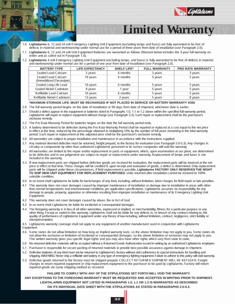
1.0 Lightalarms 6, 12 and 24 volt Emergency Lighting Unit Equipment (excluding lamps and fuses) are fully warranted to be free of defects in material and workmanship under normal use for a period of three years from date of installation (see Paragraph 2.0).
1.1 Lightalarms 6, 12 and 24 volt Unit Equipment Batteries are warranted as follows (Warrant below includes the 3-year full warranty on entire unit as called out in Paragraph 1.0).
1.2 Lightalarms 4 volt Emergency Lighting Unit Equipment (excluding lamps, and fuses) is fully warranted to be free of defects in material and workmanship under normal use for a period of one year from date of installation (see Paragraph 2.0).
*MAXIMUM STORAGE LIFE. MUST BE RECHARGED IF NOT PLACED IN SERVICE OR BATTERY WARRANTY VOID2.0 The full warranty period begins on the date of installation or 90 days from date of shipment, whichever date is earlier.
2.1 Should a defect appear in the equipment or batteries listed in Paragraphs 1.0, 1.1 or 1.2 above within the specified full warranty period, Lightalarms will repair or replace equipment without charge (see Paragraph 3.3). Such repair or replacement shall be the purchaser’s exclusive remedy.
2.2 The Pro Rata Warranty Period for batteries begins on the date the full warranty period ends.
2.3 A battery determined to be defective during the Pro Rata Warranty Period shall be repaired or replaced at a cost equal to the net price in effect at the time, reduced by the percentage obtained in multiplying 10% by the number of full years remaining in the total warranty period. Such repair or replacement at this adjusted price shall be the purchaser’s exclusive remedy.
3.0 All warranties are subject to proper installation and maintenance in accordance with the instructions supplied.
3.1 Any material deemed defective must be returned, freight prepaid, to the factory for evaluation (see Paragraph 5.0-5.3). Any changes in circuitry or components by other than authorized Lightalarms personnel or its service companies will void the warranty.
3.2 All warranties are limited to the repair and/or replacement or parts or equipment, which, upon examination at our plant, are determined to be defective and in our judgement are subject to repair or replacement under warranty. Replacement of lamps and fuses is not included in the warranty.
3.3 If new replacement parts are shipped before defective goods are received for evaluation, the replacement parts will be invoiced at the net price in effect at that time. These charges will be credited if, upon receipt and evaluation of goods, a defect is determined. Only replacement parts will be shipped under these circumstances, if field replacement is possible. Lightalarms FACTORY ONLY RESERVES THE RIGHTTO SHIP NEW UNIT EQUIPMENT FOR REPLACEMENT PURPOSES. Units returned after installation cannot be restored to 100% saleable condition.
4.0 In no event shall Lightalarms be liable for backcharges of any kind, including, without limitation, labor charges for field repair or late penalties.
4.1 This warranty does not cover damages caused by improper maintenance of installation or damage due to installation in areas with other than normal temperatures and environmental conditions per application specifications. Lightalarms assumes no responsibility for any damage to people, property, apparatus or otherwise resulting from improper installation or maintenance of its Emergency Lighting Unit Equipment.
4.2 This warranty does not cover damages caused by abuse, fire or Act of God.
4.3 In no event shall Lightalarms be liable for incidental or consequential damages.
4.4 The foregoing warranty is in lieu of all other warranties, expressed or implied, or merchantability, fitness for a particular purpose or any other thing. Except as stated in this warranty, Lightalarms shall not be liable for any defects in, or breach of any contract relating to, the quality of performance of Lightalarms Equipment under any theory of law including, without limitation, contract, negligence, strict liability or misrepresentation.
4.5 Lightalarms warranty coverage shall not apply to any equipment of another manufacturer used in conjunction with LightalarmsEquipment.
4.6 Some states do not allow limitation on how long an implied warranty lasts, so the above limitation may not apply to you. Some states donot allow the exclusion or limitation of incidental or consequential damages, so the above limitation or exclusion may not apply to you.This written warranty gives you specific legal rights and you may also have other rights which vary from state to state.
5.0 No returned defective materials will be accepted without a Returned Goods Authorization issued in writing by an authorized Lightalarms employee.
5.1 Purchaser is responsible for secure packing of returned materials to provide best possible assurance against damage in shipment.
5.2 Defective batteries of any kind must not be returned to Lightalarms’s factory without strict adherence to special instructions for handling and shipping.WARNING Never ship a refillable wet battery in any type of emergency lighting equipment. Failure to adhere to this policy will void warranty.
5.3 Defective goods returned to the factory must be shipped prepaid. COLLECT RETURNED SHIPMENT WILL BE REFUSED. Freight charges to return repaired equipment or ship replacement equipment to the purchaser to be paid by Lightalarms. Factory will return repaired goods via same shipping method as received.
FAILURE TO COMPLY WITH ANY OF THE STIPULATIONS SET FORTH WILL VOID THE WARRANTY.ANY EXCEPTIONS TO THE FOREGOING WARRANTY MUST BE REQUESTED AND ACCEPTED IN WRITING PRIOR TO SHIPMENT.
LIGHTALARMS EQUIPMENT NOT LISTED IN PARAGRAPHS 1.0, 1.1 OR 1.2 IS WARRANTED AS DESCRIBED ON ITS INDIVIDUAL DATA SHEET WITH THE STIPULATIONS AS STATED IN PARAGRAPHS 2.0-5.3.
BATTERY TYPE LIFE EXPECTANCY SHELF LIFE* FULL WARRANTY PRO RATA WARRANTYSealed Lead Calcium 5 years 6 months 3 years 3 yearsSealed Lead Calcium 10 years 6 months 5 years 5 years(Immobilized Electrolyte)Sealed Long Life Lead 10 years 6 months 5 years 5 years
Sealed Nickel Cadmium 8 years 1 year 5 years 5 yearsRefillable Lead Calcium 10 years 6 months 5 years 5 years
Refillable Nickel Cadmium 13 years 2 years 5 years 8 years