introduction to automation - … · kawalan automasi : plc, microcontroller, relay, pid (depend on...
TRANSCRIPT

INTRODUCTION TO AUTOMATION
Automation system is the system effectiveness or devices to operate wisely, without or under minimal human
monitoring level. Automation including 3 steps that is input ( sensor, keyboard, cd drive, tape) processing (PLC, CPU,
software, relay, valve ) and output (actuator, monitor, AC/DC motor, servo, solenoid and valve)
HISTORY
1. MANUAL ULANG ALIK 2.PENJENTERAAN 3. AUTOMATION
3 INTELIGENT CONVEYOR SYSTEM (AUTOMATION)
INPUT PROCESSING OUTPUT
MANUAL
REPETATIVE MECHANIZATION AUTOMATION
MANUAL REPETATIVE Kerja yang sama diulangi dengan
menggunakan kekuatan fizikal dengan sdikit alat atau
tanpa alat.
PENJENTERAAN Mesin digunakan tapi tenaga manusia
masih diperlukan utk menyiapkan kerja cth mesin
pengisi memuatkan beras kedalam guni, tali sawat bg
memudahkan kerja

AUTOMASI : sistem kawalan, mesin, proses, minimum 1 org pekerja
KAWALAN AUTOMASI : plc, microcontroller, relay, pid (depend on cost, kesesuaian)
Why we needs automation
1. to improve quality of the product and keeping quality consistency
2. to improve the quantity of the production line.
3. To reducing the manpower support.
Which area that needs the automation system;
1. Assembly Line (Talian pemasangan)
2. Pengujian dan Pengemasan Bungkusan (Packaging)
3. Hazard and Dangerous Zone
4. High speed and precision process, computer integrated machine (CIM)
THE ADVANTAGES OF AUTOMATION
i) Reducing the labour cost
ii) Improving the eff. In term of quality and quantity
iii) Flexibility in market demand in term of product changes and rearrangement of the manuf. Process
iv) Reliability : Duration of the process could be constantly operated by keeping the product quality.
v) Repeatability : the output can be scheduled and controlled
vi) Safe : To minimize and avoiding the human from contact with high risk / hazard area
vii) Labor shortage problem solving
AUTOMASI : tenaga manusia digantikan dgn mesin yg
dikawal oleh pengawal utk menghasilkan sesuatu
produk. Manusia hnya mengawal pada sistem kawalan
dn akan mengurangkn buruh di pasaran.
ADVANTAGES IN PROCESS FROM GRAPHICAL GIVE US; Automatically rice packaging, constant in amount for 1 packet of rice. Intelligent distribute system using in make whether to accept or reject the rice quality Robot Arm is using in goods handling and placing.

Definition of Industrial Automation
Automation is basically the delegation of human control function to technical equipments for
1) Increasing Productivity
2) Increasing Quality
3) Reducing Cost
4) Increasing Safety in working conditions.
Industrial automation is the use of robotic devices to complete manufacturing tasks. In this day and age of
computers, industrial automation is becoming increasingly important in the manufacturing process because
computerized or robotic machines are capable of handling repetitive tasks quickly and efficiently. Machines used
in industrial automation are also capable of completing tasks that are not desirable to workers. In addition, the
company can save money because it does not need to pay for expensive benefits for this specialized machinery. There
are both pros and cons for a company when it comes to industrial automation. On the plus side, with soaring
healthcare costs, paid days off, vacation time, and other costly employee benefits, companies can save money
with industrial automation. While robotic machinery can initially be extremely expensive, the loss of monthly wages
for production workers leads to incredible savings for the company. While machinery used
for industrial automation can break down, it does not happen often. If it does, only a handful of maintenance or
computer engineers are needed to handle repairs and get lines running smoothly again.
Advantages and disadvantages of Automation
Advantage of automation Disadvantages of automation
Replacing human operators in tasks that
involve hard physical or monotonous
work.
Technology limits. Current technology is unable to automate all
the desired tasks.
Replacing humans in tasks that should
be done in dangerous environments (i.e.
fire, space, volcanoes, nuclear facilities,
underwater, etc)
Unpredictable development costs. The research and
development cost of automating a process is difficult to predict
accurately beforehand. Since this cost can have a large impact
on profitability, it's possible to finish automating a process only
to discover that there's no economic advantage in doing so.
Making tasks that are beyond the
human capabilities such as handling
too heavy loads, too large objects, too
Initial costs are relatively high. The automation of a new
product required a huge initial investment in comparison with
the unit cost of the product, although the cost of automation

hot or too cold substances or the
requirement to make things too fast or
too slow
is spread in many product batches. The automation of a plant
required a great initial investment too, although this cost is
spread in the products to be produced.
AUTOMATION IN PRODUCTION SYSTEMS
Some elements of the production systems are likely to be automated,where as the others will be operated manually
or clerically. For ourpurposes here, automation can be defined as a technology concernedwith the application of
mechanical, electronic and computer basedsystems to operate and control production.In modern production systems,
the two categories overlap to someextent, because the automated manufacturing systems operating on thefactory
floor are themselves often implemented by computer systems andconnected to the computerized manufacturing
support systems andmanagement information system operating at the plant and enterpriselevels. The term computer
integrated manufacturing is used to indicatethis extensive use of computers in production systems

ARM ROBOTS
Joint action
Joint action any productive way in which multiple active resources participate in accomplishing a single function,
including coordination, collaboration, cooperation, unwitting assistance, witting non-interference, and even
competition. The critical factor is that the interaction among the resources acting jointly involves some
communication on the part of each participating actor, and the joint action accomplishes some part of a function of
the larger system.
Reliability
The reliability concern is: What are the business requirements for the system to be up and running, and can the
integrated system meet those requirements? The requirements for the system to be up and running relate to the
requirements for support of the business process, typically in terms of availability, timeliness, continuity, and
maintenance of state.
Degree Of Fredom
Degree of freedom (DOF) of a mechanical system is the number of independent parameters that define its
configuration. It is the number of parameters that determine the state of a physical system and is important to the
analysis of systems of bodies in mechanical engineering, aeronautical engineering, robotics, and structural
engineering.
The position of a single car (engine) moving along a track has one degree of freedom, because the position of the car is
defined by the distance along the track. A train of rigid cars connected by hinges to an engine still has only one degree
of freedom because the positions of the cars behind the engine are constrained by the shape of the track.
An automobile with highly stiff suspension can be considered to be a rigid body traveling on a plane (a flat, two-
dimensional space). This body has three independent degrees of freedom consisting of two components of translation
and one angle of rotation. Skidding or drifting is a good example of an automobile's three independent degrees of
freedom.
Link And Joint
Arotational joint (R) is identified by its motion, rotation about an exis perpendicular to the adjoint links. Here the
length of adjoint links to do not change but the relative position of the link with respect to one another changes as the
rotation takes places
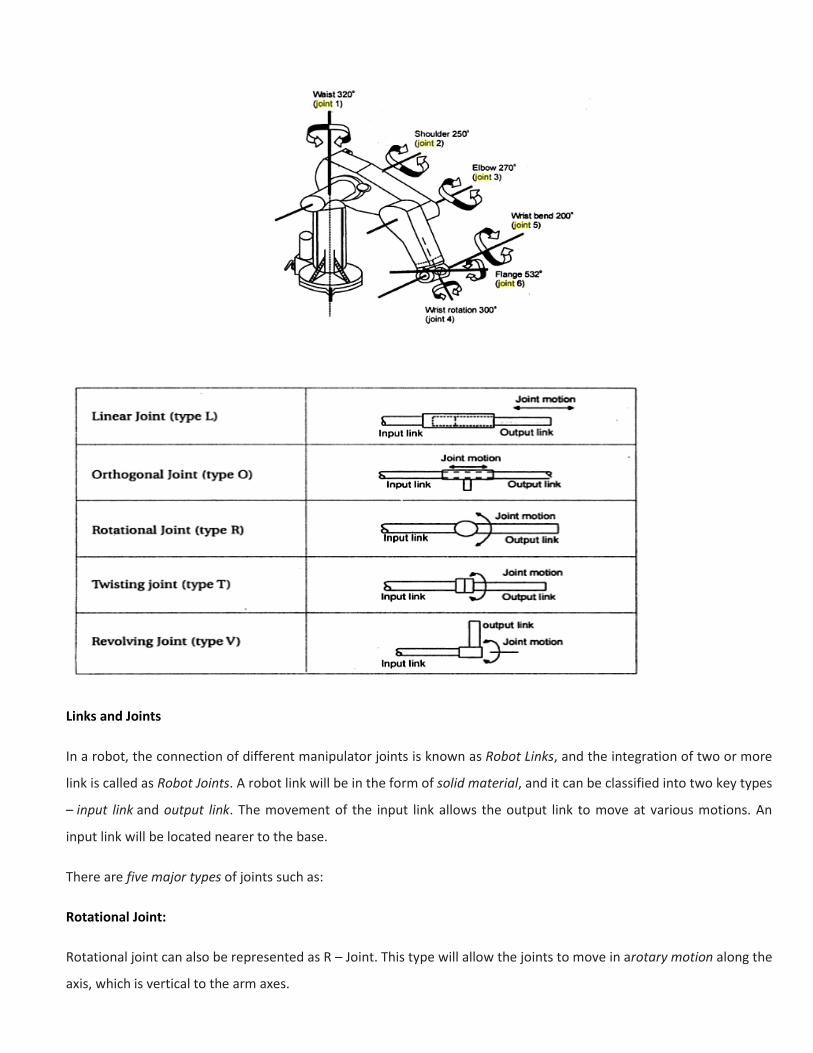
Links and Joints
In a robot, the connection of different manipulator joints is known as Robot Links, and the integration of two or more
link is called as Robot Joints. A robot link will be in the form of solid material, and it can be classified into two key types
– input link and output link. The movement of the input link allows the output link to move at various motions. An
input link will be located nearer to the base.
There are five major types of joints such as:
Rotational Joint:
Rotational joint can also be represented as R – Joint. This type will allow the joints to move in arotary motion along the
axis, which is vertical to the arm axes.

Linear Joint:
Linear joint can be indicated by the letter L – Joint. This type of joints can perform both translational and sliding
movements. These motions will be attained by several ways such as telescoping mechanism and piston. The two links
should be in parallel axes for achieving the linear movement.
Twisting Joint:
Twisting joint will be referred as V – Joint. This joint makes twisting motion among the output and input link. During
this process, the output link axis will be vertical to the rotational axis. The output link rotates in relation to the input
link.
Orthogonal Joint:The O – joint is a symbol that is denoted for the orthogonal joint. This joint is somewhat similar to
the linear joint. The only difference is that the output and input links will be moving at the right angles.
Revolving Joint:
Revolving joint is generally known as V – Joint. Here, the output link axis is perpendicular to the rotational axis, and the
input link is parallel to the rotational axes. As like twisting joint, the output link spins about the input link.
GRIPPERS
Grippers are not only required for use with industrial robots: they are a universal component in automation. Grippers
operate with:
Industrial robots (handling and manipulation of objects).
-assembling, machining, and packaging).
-guided manipulators (remote prehension, medical, aerospace, nautical)
-carrying equipment).

Possibilities for prehension of a spherical object. (1) pure enclosing without clamping, (2) partial form fit combine with
clamping force, (3) pure force closure, (4) holding with vacuum air (pneumatic force closure), (5) retention using
magnetic field (force field), (6) retention using adhensive media.
Types of grippers used in industrial robot applications include the following:
• mechanical grippers, consisting of two or more fingers that can be actuated by the robot controller to open and dose
to grasp the workpart; Figure 3.63 shows a two finger gripper
• vacuum grippers, in which suction cups are used to hold flat objects
• magnetized devices, for holding ferrous parts
• adhesive devices, where an adhesive substance is used to hold a flexible material such as a fabric
• simple mechanical devices such as hooks and scoops.

SENSOR
General Characteristics of sensor
Sensor is a device that when exposed to a physical phenomenon (temperature, displacement, force, etc.) produces a
proportional output signal (electrical, mechanical, magnetic, etc.). The term transducer is often used synonymously
with sensors. However, ideally, a sensor is a device that responds to a change in the physical phenomenon.
Sensors are transducers when they sense one form of energy input and output in a different form of energy. For
example, a thermocouple responds to a temperature change (thermal energy) and outputs a proportional change in
electromotive force (electrical energy). Therefore, a thermocouple can be called a sensor and or transducer.
Figurer 5.1: A typical control system
Furthermore, sensors are classified as analog or digital based on the type of output signal. Analog sensors produce
continuous signals that are proportional to the sensed parameter and typically require analog-to-digital conversion
before feeding to the digital controller. Digital sensors on the other hand produce digital outputs that can be directly
interfaced with the digital controller. Often, the digital outputs are produced by adding an analog-to-digital converter
to the sensing unit. If many sensors are required, it is more economical to choose simple analog sensors and interface
them to the digital controller equipped with a multi-channel analog-to-digital converter.

STEPPER MOTOR
DESCRIBE THE THEORY:
Stepper motors consist of a permanent magnetic rotating shaft, called the rotor, and electromagnets on the stationary
portion that surrounds the motor, called the stator. Figure 1 illustrates one complete rotation of a stepper motor. At
position 1, we can see that the rotor is beginning at the upper electromagnet, which is currently active (has voltage
applied to it). To move the rotor clockwise (CW), the upper electromagnet is deactivated and the right electromagnet
is activated, causing the rotor to move 90 degrees CW, aligning itself with the active magnet. This process is repeated
in the same manner at the south and west electromagnets until we once again reach the starting position
Figure 1
In the above example, we used a motor with a resolution of 90 degrees or demonstration purposes. In reality, this
would not be a very practical motor for most applications. The average stepper motor's resolution -- the amount of
degrees rotated per pulse -- is much higher than this. For example, a motor with a resolution of 5 degrees would move
its rotor 5 degrees per step, thereby requiring 72 pulses (steps) to complete a full 360 degree rotation.

Figure 2
We may double the resolution of some motors by a process known as "half-stepping". Instead of switching the next
electromagnet in the rotation on one at a time, with half stepping you turn on both electromagnets, causing an equal
attraction between, thereby doubling the resolution. As you can see in Figure 2, in the first position only the upper
electromagnet is active, and the rotor is drawn completely to it. In position 2, both the top and right electromagnets
are active, causing the rotor to position itself between the two active poles. Finally, in position 3, the top magnet is
deactivated and the rotor is drawn all the way right. This process can then be repeated for the entire rotation.
THEORY :
Stepper motors have smooth armatures and include a permanent magnet core that is magnetized widthwise or
perpendicular to its rotation axis. These motors usually have two independent windings, with or without center taps.
The most common step angles for PM motors are 45° and 90°, but motors with step angles as fine as 1.8°per step as
well as 7.5, 15, and 30° per step are generally available. Armature rotation occurs when the stator poles are
alternately energized and de-energized to create torque. A 90° stepper has four poles and a 45° stepper has eight
poles, and these poles must be energized in sequence. Permanent -magnet steppers step at relatively low rates, but
they can produce high torques and they offer very good damping characteristics.
Stepper motors are controlled directly. The primary command and control variable is the step position. This is in
contrast to d.c motors where the control variable is the motor voltage and the command variable may be either
position or velocity. A d.c motor requires a feedback control system and controls the position indirectly. A stepper
motor system is normally operated “open loop”.

REFER TO THE PICTURE BELOW AND BY USING ALL YOUR KNOWLEDGE AND SOURCE, GIVE AN EXPLANATION TO
DESCRIBE THE THEORY AND ITS FUNCTION IN OUR INDUSTRY TODAY..
Penjelasan kepada huraikan teori
Motor stepper menyediakan satu cara untuk kedudukan terperinci dan kawalan kelajuan tanpa menggunakan sensor
maklum balas. Operasi asas motor stepper membolehkan aci bergerak jumlah yang tepat dari darjah setiap kali satu
denyutan elektrik dihantar kepada motor. Oleh kerana aci motor bergerak hanya beberapa darjah yang ia direka untuk
apabila setiap nadi dihantar, anda boleh mengawal denyutan yang dihantar dan mengawal kedudukan dan kelajuan.
Pemutar motor menghasilkan tork daripada interaksi antara medan magnet di pemegun dan pemutar. Kekuatan
medan magnet adalah berkadar dengan jumlah arus dihantar ke pemegun dan bilangan lilitan pada belitan. Motor
pelangkah menggunakan teori beroperasi magnet untuk membuat aci motor bertukar jarak yang terperinci apabila
satu denyutan elektrik disediakan. Rajah 1 menunjukkan pandangan tipikal keratan rentas pemutar dan pemegun
motor stepper. Daripada rajah ini anda dapat melihat bahawa pemegun (pegun penggulungan) mempunyai lapan
tiang, dan pemutar mempunyai enam tiang (tiga magnet lengkap). Pemutar akan memerlukan 24 denyutan elektrik
untuk menggerakkan 24 langkah-langkah untuk membuat satu putaran lengkap. Satu lagi cara untuk mengatakan ini
adalah bahawa pemutar akan bergerak tepat 15 ° untuk setiap nadi elektrik motor menerima. Bilangan darjah
pemutar akan bertukar apabila satu denyutan elektrik dihantar ke motor boleh dikira dengan membahagikan bilangan
darjah dalam satu putaran aci (360 °) dengan jumlah kutub (utara dan selatan) di pemutar . Dalam motor stepper ini
360 ° dibahagikan dengan 24 untuk mendapatkan 15 °.
Apabila tiada kuasa dibekalkan kepada motor, baki kemagnetan dalam magnet pemutar akan menyebabkan pemutar
untuk menahan atau menyelaraskan satu set kutub magnet dengan kutub magnet salah satu magnet pemegun. Ini
bermakna bahawa pemutar akan mempunyai 24 kedudukan penahan. Apabila pemutar adalah dalam kedudukan
Penahan, ia akan mempunyai cukup tenaga magnet untuk menjaga aci daripada bergerak ke kedudukan seterusnya.
Inilah yang membuat pemutar merasa seperti ia menekan dari satu kedudukan ke depan kerana anda memutar
pemutar dengan tangan tanpa kuasa digunakan.

Fungsi dalam industri hari ini
Motor stepper telah menjadi komponen penting untuk aplikasi dalam pelbagai industri yang berbeza. Yang berikut
adalah senarai industri menggunakan motor stepper:
Pesawat - Dalam industri pesawat, motor pelangkah digunakan dalam instrumentasi pesawat, antena dan
penderiaan aplikasi dan peralatan pengimbasan
Automotif - Industri automotif melaksanakan motor pelangkah untuk aplikasi berkaitan kawalan pelayaran,
peranti penderiaan, dan kamera. Pihak tentera juga menggunakan motor stepper dalam pemakaiannya
antena kedudukan
Kimia - Industri kimia menggunakan motor stepper untuk dicampur dan persampelan bahan. Mereka juga
menggunakan pengawal motor stepper dengan motor stepper tunggal dan multi-paksi untuk ujian peralatan
Elektronik Pengguna dan Peralatan Pejabat - Di dalam industri elektronik pengguna, motor pelangkah
digunakan secara meluas dalam kamera digital untuk fokus dan fungsi zoom ciri. Dalam peralatan pejabat,
motor pelangkah dilaksanakan dalam peralatan imbasan berasaskan PC, pemacu storan data, pemacu cakera
optik memandu mekanisme, pencetak, pengimbas dan
Permainan - Dalam industri permainan, motor pelangkah digunakan secara meluas dalam aplikasi seperti slot
dan mesin loteri, pemintal roda, dan walaupun shufflers kad
Industri - Di dalam industri perindustrian, motor pelangkah digunakan dalam tolok automotif, mesin alat
dengan tunggal dan multi-paksi stepper motor pengawal, dan kit retrofit yang menggunakan pengawal motor
pelangkah juga. Motor stepper juga boleh didapati dalam kawalan mesin CNC
Perubatan - Dalam industri perubatan, motor pelangkah digunakan dalam pengimbas perubatan, kawalan
gerakan mikroskopik atau nanoscopic peranti automatik, pendispensan pam, dan alat kromatografi automatik
penyuntik. Motor stepper juga ditemui di dalam fotografi digital pergigian (X-RAY), pam cecair, alat
pernafasan, dan analisis jentera darah, centrifuge
Peralatan Saintifik Instrumen -Scientific melaksanakan motor stepper dalam kedudukan sebuah balai cerap
teleskop, spectrographs, dan centrifuge
Sistem Pengawasan - motor stepper digunakan dalam pengawasan kamera
FUNCTION IN INDUSTRY :
Used in automotive applications for electronic throttle control, dashboard indicators, and climate control
systems.
Also found in industrial equipment such as robotics, electronic component handlers, testers, dispensers and
other manufacturing equipment.
Stepper motors are often controlled using special function ICs that provide limited control functionally.

FUNCTION:
Motors convert electrical energy into mechanical energy. A stepper motor converts electrical pulses into specific
rotational movements. The movement created by each pulse is precise and repeatable, which is why stepper motors
are so effective for positioning applications.