introductionesh-docdb.fnal.gov/cgi-bin/retrievefile?docid=367&version... · web viewapi...
TRANSCRIPT
Fermilab ES&H ManualFESHM 5032.1February 2011
FESHM 5032.1: LIQUID NIROGEN DEWAR INSTALLATION AND OPERATION RULES
Revision History
Author Description of Change Revision No. & DateArkadiy Klebaner Revision 1 – to incorporate comments from
experts and minor editorial changes.
1. Added reference to database for the nitrogen dewars maintained by the Business Services Section
2. Changed Division/Section to Division/Section/Center
3. Changed Laboratory Safety Committee to FESHCom
Revision 1February 2011
Fermilab ES&H Manual 5032.1-1WARNING: This manual is subject to change. The current version is maintained on the ESH Section website. Rev. 2/2011

Fermilab ES&H ManualFESHM 5032.1February 2011
TABLE OF CONTENTS
1.0 INTRODUCTION.......................................................................................................................22.0 SPECIAL RESPONSIBLILITIES..............................................................................................2
2.1 The Division/Section/Center Head.....................................................................................22.2 The Responsible Party........................................................................................................22.3 The Business Services Section...........................................................................................22.4 The ES&H Section.............................................................................................................22.5 The Cryogenic Safety Subcommittee.................................................................................3
3.0 POLICY......................................................................................................................................34.0 TECHNICAL APPENDIX A......................................................................................................4
Fermilab ES&H Manual 5032.1-1WARNING: This manual is subject to change. The current version is maintained on the ESH Section website. Rev. 2/2011
Fermilab ES&H ManualFESHM 5032.1February 2011
1.0 INTRODUCTION
This chapter defines procedures for installing liquid nitrogen dewars and standardizes the safety documentation used in the review process. Mandatory rules must be followed in all cases. Recommended rules are included but are not required for safety purposes. While specifically intended for nitrogen dewars, some parts of these procedures may be used as a guide for installing other dewars.
2.0 SPECIAL RESPONSIBLILITIES
2.1 The Division/Section/Center Head that controls the area of operations where the dewar resides is responsible for carrying out the requirements of this chapter. He/She shall arrange for the initial review of the dewar by a qualified person and designate a Responsible Party for the dewar.
2.2 The Responsible Party: Should be qualified to provide on-going management and verification of all safety aspects for
the dewar as specified in the Technical Appendix for this Chapter. Shall verify that installation, safety devices, and operation procedures (including liquid fill
and withdrawal) for the dewar are in compliance with the most recent equipment characteristics and practices of LN2 supplier, as well as with most recent equipment and system configuration of the end users.
Shall inform the Business Services Section of the need to be listed in the database of the liquid nitrogen dewars maintained by the Business Section, and therefore informed by the Business Section of any modifications to the operations of the dewars initiated by the liquid nitrogen vendors.
Shall designate a Contact Person for the dewar. The Responsible Party shall notify BSS of this designation, and assure that the Contact Person is identified on the information label attached to the dewar.
2.3 The Business Services Section:Shall maintain the database for the nitrogen dewars and make it available for viewing on the web. The database if located in:http://bss-support.fnal.gov/products/bssdocposting.nsf/pages/Liquid+Nitrogen
It should be understood that each liquid nitrogen supplier is under contractual obligations to provide the most recent equipment characteristics and practices used in filling the dewars to the Business Section, which should in turn make the information available to each concerned Responsible Party.
2.4 The ES&H Section: Shall audit the divisions and sections on their compliance with this chapter.
Fermilab ES&H Manual 5032.1-2WARNING: This manual is subject to change. The current version is maintained on the ESH Section website. Rev. 2/2011
Fermilab ES&H ManualFESHM 5032.1February 2011
2.5 The Cryogenic Safety Subcommittee: Shall serve the division/section heads and the ES&H Section in a consulting capacity on all
nitrogen dewar matters. Shall insure that every liquid nitrogen dewar, within the scope of the technical appendix, has
completed its safety review and has an assigned Responsible Party and Contact Person. Should conduct a bi-annual audit of all liquid nitrogen dewars to insure that the systems are
up to date.
3.0 POLICY
All liquid nitrogen dewars, installed and used at Fermilab shall be in accordance with the mandatory provisions of this chapter in the technical appendix, which is attached.
Fermilab ES&H Manual 5032.1-3WARNING: This manual is subject to change. The current version is maintained on the ESH Section website. Rev. 2/2011
Fermilab ES&H ManualFESHM 5032.1TA
February 2011
4.0 TECHNICAL APPENDIX A
Technical Appendix to – LIQUID NITROGEN DEWARE INSTALLATION RULES
TABLE OF CONTENTS1.0 SCOPE 42.0 REFERENCE DOCUMENTS 43.0 PROVISIONS & PRACTICES 54.0 VALVES & INSTRUMENTATION 5 A) MANDATORY PROVISIONS 5 B) STANDARD PRACTICES 6 C) SUGGESTED PRACTICES 65.0 PIPING 7 A) MANDATORY PROVISIONS 7 B) STANDARD PRACTICES 7 C) SUGGESTED PRACTICES 86.0 RELIEF DEVICES: PIPING & INSTALLATION 8 A) MANDATORY PROVISIONS 8 B) SUGGESTED PRACTICES 97.0 RELIEF DEVICES: SIZING 9 A) MANDATORY PROVISIONS 98.0 GENERAL 13 A) MANDATORY PROVISIONS 13 B) STANDARD PRACTICES 13
1.0 SCOPE
This standard applies to all vacuum insulated liquid nitrogen dewars owned by Fermilab, both mobile and stationary, which are filled from tankers at Fermilab. Specifically excluded are the vendor supplied 180L liquid nitrogen dewars. The installation rules, which follow, are intended to provide for the safe and efficient operation of these dewars. Although this standard does not address the design, fabrication, and testing of the pressure vessels themselves, these requirements are given in Fermilab ES&H Safety Manual chapters 5031 and 5034. The Fermilab standard for vacuum vessels is presented in section 5033.
2.0 REFERENCE DOCUMENTS
Compressed Gas AssociationCGA S-1.3 “Pressure Relief Device Standards Part 3 –Stationary Storage Containers for
Compressed Gases”CGA 341 “Standard for Insulated Cargo Tank Specification for Nonflammable
Cryogenic Liquids”CGA V-6 “Standard Cryogenic Liquid Transfer Connections”CGA PS-8-2003 “Position Statement on the Protection of Cryogenic Storage Tanks from
Overpressure During Operator-attended Refill”
Fermilab ES&H Manual 5032.1TA-Rev. 2/2011
WARNING. This paper copy may be obsolete soon after it is printed. The current version of this FESHM Chapter is found athttp://www-esh.fnal.gov/pls/default/esh_manuals.html
Fermilab ES&H ManualFESHM 5032.1TA
February 2011
American National Standards InstituteB3 1.3 “Process Piping”
American Petroleum InstituteAPI 520 “Recommended Practice: Sizing, Selection and Installation of Pressure-Relieving
Systems in Refineries”API 521 “Recommended Practice: Guide for Pressure-Relieving and Depressuring
Systems”
American Society of Mechanical EngineersSect. VIII “Boiler & Pressure Vessel Code- Pressure Vessels”
Note: All Standards and Practices should be of latest publication.
3.0 PROVISIONS & PRACTICES
The provisions of this standard are divided into three categories:
1.) Mandatory provisions impact the safe operation of the dewar. They are subject to the review of the cryogenic safety committee and noncompliance may result in a negative response to a request for approval to operate.
2.) Standard practices impact the efficient operation of the dewar. They are considered very important to the standardization and ease of operation of liquid nitrogen dewar installations at Fermilab. Failure to follow these practices does not compromise the safety of the vessels. Noncompliance in this area must be accompanied by a written sign-off by the appropriate Division or Section Head, signifying his approval to allow the installation of this dewar in a nonstandard way.
3.) Suggested practices may lead to more efficient operation of the dewar. These practices constitute the collective experiences of present dewar installations and are deemed to offer guidelines for setting up an efficient operation. A decision of whether to follow these practices is left in the hands of the system designer; however, the cryogenic safety committee may elect to note areas of noncompliance in its review.
4.0 VALVES & INSTRUMENTATION
A) MANDATORY PROVISIONS
1.) Reliable means of measuring the liquid level in the dewar.Reason: Aid in preventing overfilling the dewar.
2.) Pressure gauge to sense ullage pressure.Reason: Aid in preventing over pressurization of the dewar.
3.) Fill & withdrawal valve(s).Reason: Operate and isolate dewar.
4.) Required relief devices.Note: See Sections 6.0 and 7.0 for relief device requirements.Reason: Protect the vessel from overpressure.
5.) Means, other than the required relief devices, to vent the vessel, i.e., blowdown valve.Fermilab ES&H Manual 5032.1TA-
Rev. 2/2011
WARNING. This paper copy may be obsolete soon after it is printed. The current version of this FESHM Chapter is found athttp://www-esh.fnal.gov/pls/default/esh_manuals.html
Fermilab ES&H ManualFESHM 5032.1TA
February 2011
Reason: Avoid using relief devices to control pressure during filling.6.) The MAWP of all valves and instruments must be greater than or equal to the maximum
pressure to which they can be exposed in all modes of operations.Reason: Ensure that the pressure ratings of valves and instruments are sufficient.
7.) All valves and instruments, which can communicate with cryogens in trapped volumes, must be protected with trapped volume reliefs.Reason: Ensure that the component pressure rating is not exceeded.
B) STANDARD PRACTICES
1.) Differential pressure liquid level gauge with isolation valves and a calibration checking feature such as a 3 valve manifold.Reason: Check calibration and change instrument.
2.) Isolation valve for the pressure gauge.Reason: Check calibration and change instrument.
3.) Full trycock valve.Reason: Aid in preventing overfilling the dewar.
4.) Primary pressure regulation device other than required relief devices.Reason: Ensure that the primary relief valve is not used as a pressure regulator.
5.) Vacuum gauge on vacuum vessel.Reason: Check insulating vacuum.
6.) Vacuum pumpout valve, capped off to prevent inadvertent opening.Reason: Evacuate vacuum vessel.
7.) Drain valve on fill line.Reason: Provide for venting trapped liquid before delivery hose is disconnected.
8.) Pressure building coil.Reason: Aid in maintaining dewar pressure.
C) SUGGESTED PRACTICES
1.) Isolation valves at both ends of pressure building loop.Reason: Provide ease of repair of pressure building coil and control valve.
2.) Isolation valve for vacuum gauge.Reason: Allow calibration or replacement of gauge.
3.) Top & bottom fill valves.Reason: Provide more versatile dewar operation.
4.) Liquid and gas withdrawal valves.Reason: Provide more versatile dewar operation.
5.) Strainer on liquid fill line.Reason: Prevent particulate contamination of dewar from delivery truck.
6.) Check valve on liquid fill line.Reason: Prevent loss of product in case of delivery hose failure.
7.) Filters on vacuum pumpout line and gauge line.Reason: Protect equipment from perlite damage.
Fermilab ES&H Manual 5032.1TA-Rev. 2/2011
WARNING. This paper copy may be obsolete soon after it is printed. The current version of this FESHM Chapter is found athttp://www-esh.fnal.gov/pls/default/esh_manuals.html
Fermilab ES&H ManualFESHM 5032.1TA
February 2011
5.0 PIPING
A) MANDATORY PROVISIONS
1.) Standoffs to a carbon steel vacuum jacket must ensure an acceptable temperature of the vessel.Reason: Constant flow through lines may provide cooling to the shell which lowers its temperature below the ASME material limit.
2.) Thermal stresses must be taken into account in designing piping and piping supports.Reason: Thermal stresses in overly constrained piping can lead to piping or support failure.
3.) All piping, which can be exposed to the vessel pressure, must have an MAWP greater than or equal to the vessel MAWP.Reason: Ensure that the piping MAWP is sufficient.
4.) All piping which can be exposed to the tanker delivery pressure must have a MAWP greater than or equal to the tanker delivery pressure or must be adequately protected from overpressure.Reason: Ensure that the piping MAWP is sufficient.
5.) All piping, which can be exposed to cryogens in trapped volumes, must be protected with trapped volume reliefs, without an intervening shut-off valve.Reason: Ensure that piping is protected from overpressure, follow CGA 341.
6.) Any portions of the piping system which were not part of the initial vessel pressure test or were modified since that test must be pressure tested in accordance with the rules of Fermilab ES&H Manual chapter 5034. For purposes of the pressure test, the MAWP of piping is to be taken as the maximum pressure to which the piping can be exposed consistent with 3.), 4.), and 5.).Reason: Piping integral to the tank has been pressure tested as part of the ASME code procedure. Piping added during installation must be checked.
7.) Piping should be in accordance with ANSI B31.3.Reason: Follow Fermilab Pressure Piping Standard 5031.1.
B) STANDARD PRACTICES
1.) The delivery tanker flow rate and pressure should be verified against the latest information provided by the suppliers. If more than one supplier can be used for filling the dewar, than the most conservative flow rate and pressure should be taken into account. It should be understood that each liquid nitrogen supplier is under contractual obligations to provide the most recent equipment characteristics and practices used in filling the dewars to the Business Section, which should in turn make the information available to each concerned Responsible Party.Reason: Follow CGA S-1.3 and PS-8-2003.
2.) All pipe, valves and fittings should be demonstrated free of leaks at the vessel’s MAWP.Reason: Follow CGA 341.
Fermilab ES&H Manual 5032.1TA-Rev. 2/2011
WARNING. This paper copy may be obsolete soon after it is printed. The current version of this FESHM Chapter is found athttp://www-esh.fnal.gov/pls/default/esh_manuals.html
Fermilab ES&H ManualFESHM 5032.1TA
February 2011
C) SUGGESTED PRACTICES
1.) Stainless steel is the preferred piping material over copper or aluminum.Reason: Take advantage of the additional strength of this material and its
weldability.Note: Cold properties should not be used.
2.) Welded connections should be used whenever possible.Reason: Follow CGA 341.
3.) Vacuum jacket the withdrawal line whenever possible.Reason: Prevent large ice build-up on constantly flowing line.
6.0 RELIEF DEVICES: PIPING & INSTALLATION
A) MANDATORY PROVISIONS
1.) Consult the ASME, CGA, & API Standards.Reason: There are standard requirements not covered by this document.
2.) The liquid container shall be protected by a minimum of two relief devices, installed to remain at ambient temperature during normal operation. Typically these devices would be one relief valve and one rupture disk, although two relief valves would be acceptable if all other conditions are met.Reason: Follow CGA S-l.3.
3.) The exhaust of liquid nitrogen reliefs and vents should not impinge on carbon steel vacuum jacket(s) or into areas which may cause harm to people.Reason: Prevent cracking carbon steel shell and personnel injury. Follow CGA S-1.3.
4.) The primary safety relief valves shall be UV stamped and shall meet the applicable requirements of ASME Code Section VIII.Reason: Follow CGA S-1.3.
5.) The design, material and location of relief devices shall be suitable for their intended service. The primary reliefs shall have direct communication with the vapor space of the container and shall be so installed that the cooling effects of the contents will not prevent their effective operation.Reason: Follow CGA S-1.3.
6.) The vent piping shall be designed to prevent accumulation of moisture at the exhaust and seat area of the relief devices, and to avoid build-up of foreign material which might affect relief capacity.Reason: Follow CGA S-l.3 and API 520 II.
7.) The inlet and vent piping of relief devices must provide for proper performance by taking into account the effect of inlet pressure losses and back pressure on the operating characteristics of the valve. The nominal size of the inlet and discharge piping and fittings connecting to the pressure relief devices shall be at least equal to the nominal size of the respective ports of the relief devices. Where there are a number of devices discharging into the same manifold, an analysis must be made of the back pressure effects on relief pressure and capacity.Reason: Follow API 520 II.
Fermilab ES&H Manual 5032.1TA-Rev. 2/2011
WARNING. This paper copy may be obsolete soon after it is printed. The current version of this FESHM Chapter is found athttp://www-esh.fnal.gov/pls/default/esh_manuals.html
Fermilab ES&H ManualFESHM 5032.1TA
February 2011
8.) The effects of mechanical (discharge reactive forces) and thermal stresses on relief device piping must be examined to assure proper operation of the relief system.Reason: Follow API 520 II.
9.) Relief devices should be designed and installed so that the possibility of tampering will be minimized.Reason: Follow CGA S-1.3.
B) SUGGESTED PRACTICES
1.) The relief system should consist of two sets of two relief devices (one relief valve and one rupture disk) with a diverter valve (adequately sized) and test valve on each side for set point checking.Reason: Allows periodic checks and repairs of relief system without interruption
of the operation.
7.0 RELIEF DEVICES: SIZING
A) MANDATORY PROVISIONS
1.) Relief device sizing must satisfy CGA S-1.3 for the following provisions:
a.) Fire conditions.(Formula deleted)
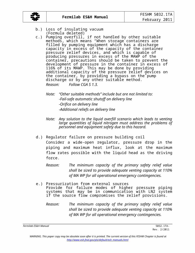
b.) Loss of insulating vacuum(Formula deleted)
c.) Pumping overfill, if not handled by other suitable methods, which means “When storage containers are filled by pumping equipment which has a discharge capacity in excess of the capacity of the container pressure relief devices, and which is capable of producing pressures in excess of the MAWP of the container, precautions should be taken to prevent the development of pressure in the container in excess of 116% of its MAWP. This may be done by providing additional capacity of the pressure relief devices on the container, by providing a bypass on the pump discharge or by any other suitable method.”Reason: Follow CGA S 1.3.
Note: “Other suitable methods” include but are not limited to:-Fail-safe automatic shutoff on delivery line-Orifice on delivery line-Additional reliefs on delivery line
Note: Any solution to the liquid overfill scenario which leads to venting large quantities of liquid nitrogen must address the problems of personnel and equipment safety due to this hazard.
d.) Regulator failure on pressure building coil
Fermilab ES&H Manual 5032.1TA-Rev. 2/2011
WARNING. This paper copy may be obsolete soon after it is printed. The current version of this FESHM Chapter is found athttp://www-esh.fnal.gov/pls/default/esh_manuals.html
Fermilab ES&H ManualFESHM 5032.1TA
February 2011
Consider a wide-open regulator, pressure drop in the piping and maximum heat influx, look at the maximum flow rates possible with the liquid head as the driving force.
Reason: The minimum capacity of the primary safety relief value shall be sized to provide adequate venting capacity at 110% of MA WP for all operational emergency contingencies.
e.) Pressurization from external sourcesProvide for failure modes of higher pressure piping systems that may be in communication with LN2 system if the source flow compromises the relief provisions.
Reason: The minimum capacity of the primary safety relief value shall be sized to provide adequate venting capacity at 110% of MA WP for all operational emergency contingencies.
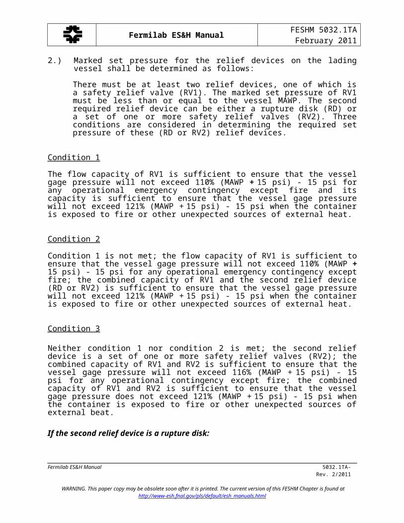
2.) Marked set pressure for the relief devices on the lading vessel shall be determined as follows:
There must be at least two relief devices, one of which is a safety relief valve (RV1). The marked set pressure of RV1 must be less than or equal to the vessel MAWP. The second required relief device can be either a rupture disk (RD) or a set of one or more safety relief valves (RV2). Three conditions are considered in determining the required set pressure of these (RD or RV2) relief devices.
Condition 1
The flow capacity of RV1 is sufficient to ensure that the vessel gage pressure will not exceed 110% (MAWP + 15 psi) - 15 psi for any operational emergency contingency except fire and its capacity is sufficient to ensure that the vessel gage pressure will not exceed 121% (MAWP + 15 psi) - 15 psi when the container is exposed to fire or other unexpected sources of external heat.
Condition 2
Condition 1 is not met; the flow capacity of RV1 is sufficient to ensure that the vessel gage pressure will not exceed 110% (MAWP + 15 psi) - 15 psi for any operational emergency contingency except fire; the combined capacity of RV1 and the second relief device (RD or RV2) is sufficient to ensure that the vessel gage pressure will not exceed 121% (MAWP + 15 psi) - 15 psi when the container is exposed to fire or other unexpected sources of external heat.
Condition 3
Neither condition 1 nor condition 2 is met; the second relief device is a set of one or more safety relief valves (RV2); the combined capacity of RV1 and RV2 is sufficient to ensure that the vessel gage pressure will not exceed 116% (MAWP + 15 psi) - 15 psi for any operational contingency except fire; the combined capacity of RV1 and RV2 is sufficient to ensure that the
Fermilab ES&H Manual 5032.1TA-Rev. 2/2011
WARNING. This paper copy may be obsolete soon after it is printed. The current version of this FESHM Chapter is found athttp://www-esh.fnal.gov/pls/default/esh_manuals.html
Fermilab ES&H ManualFESHM 5032.1TA
February 2011
vessel gage pressure does not exceed 121% (MAWP + 15 psi) - 15 psi when the container is exposed to fire or other unexpected sources of external beat.
If the second relief device is a rupture disk:
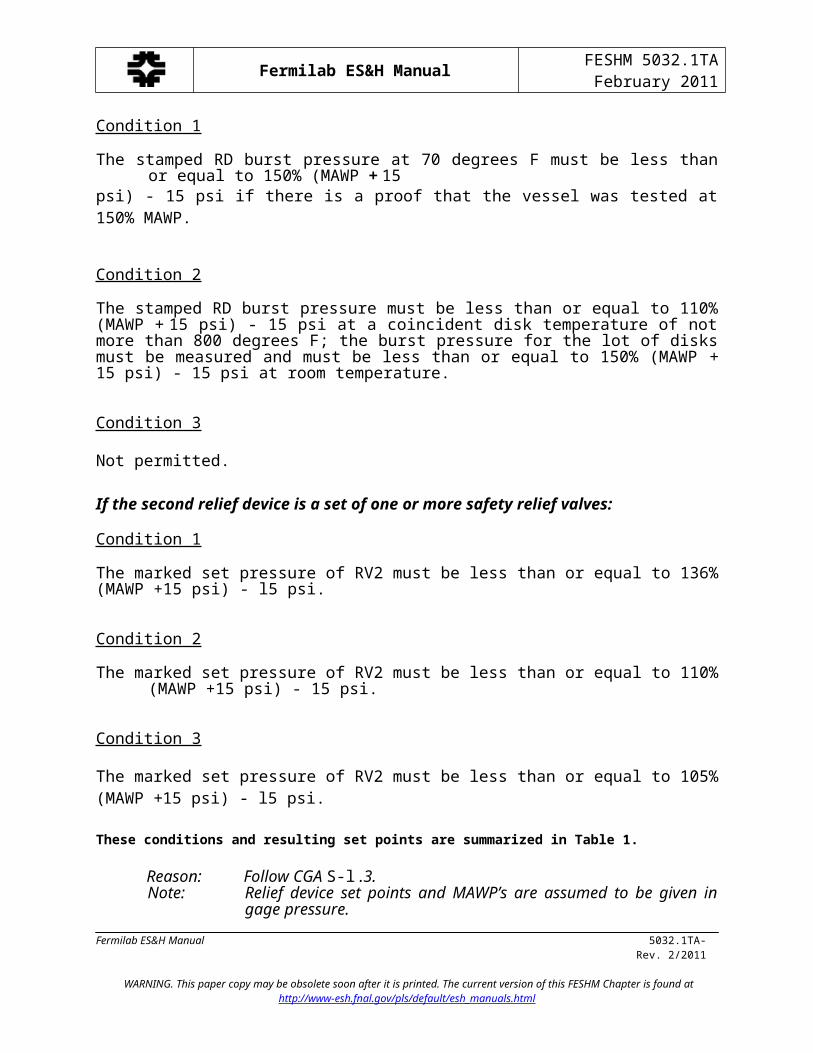
Condition 1
The stamped RD burst pressure at 70 degrees F must be less than or equal to 150% (MAWP + 15psi) - 15 psi if there is a proof that the vessel was tested at 150% MAWP.
Condition 2
The stamped RD burst pressure must be less than or equal to 110% (MAWP + 15 psi) - 15 psi at a coincident disk temperature of not more than 800 degrees F; the burst pressure for the lot of disks must be measured and must be less than or equal to 150% (MAWP + 15 psi) - 15 psi at room temperature.
Condition 3
Not permitted.
If the second relief device is a set of one or more safety relief valves:
Condition 1
The marked set pressure of RV2 must be less than or equal to 136% (MAWP +15 psi) - l5 psi.
Condition 2
The marked set pressure of RV2 must be less than or equal to 110% (MAWP +15 psi) - 15 psi.
Condition 3
The marked set pressure of RV2 must be less than or equal to 105% (MAWP +15 psi) - l5 psi.
These conditions and resulting set points are summarized in Table 1.
Reason: Follow CGA S-l .3.Note: Relief device set points and MAWP’s are assumed to be given in gage
pressure.
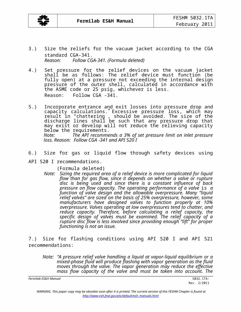
3.) Size the reliefs for the vacuum jacket according to the CGA standard CGA-341. Reason: Follow CGA-341. (Formula deleted)
Fermilab ES&H Manual 5032.1TA-Rev. 2/2011
WARNING. This paper copy may be obsolete soon after it is printed. The current version of this FESHM Chapter is found athttp://www-esh.fnal.gov/pls/default/esh_manuals.html
Fermilab ES&H ManualFESHM 5032.1TA
February 2011
4.) Set pressure for the relief devices on the vacuum jacket shall be as follows: The relief device must function (be fully open) at a pressure not exceeding the internal design pressure of the outer shell, calculated in accordance with the ASME code or 25 psig, whichever is less.Reason: Follow CGA -341.
5.) Incorporate entrance and exit losses into pressure drop and capacity calculations. Excessive pressure loss, which may result in “chattering”, should be avoided. The size of the discharge lines shall be such that any pressure drop that may exist or develop will not reduce the relieving capacity below the requirements.Note: The API recommends a 3% of set pressure limit on inlet pressure loss. Reason: Follow CGA -341 and API 520 I
6.) Size for gas or liquid flow through safety devices using API 520 I recommendations. (Formula deleted)
Note: Sizing the required area of a relief device is more complicated for liquid flow than for gas flow, since it depends on whether a valve or rupture disc is being used and since there is a constant influence of back pressure on flow capacity. The operating performance of a valve is a function of valve design and the allowable overpressure. Many “liquid relief valves” are sized on the basis of 25% overpressure, however, some manufacturers have designed valves to function properly at 10% overpressure. Valves operating at low overpressures tend to chatter, and reduce capacity. Therefore, before calculating a relief capacity, the specific design of valves must be examined. The relief capacity of a rupture disc flow is less involved since providing enough “lift” for proper functioning is not an issue.
7.) Size for flashing conditions using API 520 I and API 521 recommendations:
Note: “A pressure relief valve handling a liquid at vapor-liquid equilibrium or a mixed-phase fluid will produce flashing with vapor generation as the fluid moves through the valve. The vapor generation may reduce the effective mass flow capacity of the valve and must be taken into account. The quantity of flash vapor is commonly calculated based on adiabatic flashing from the relieving condition-either to the critical downstream pressure (the critical drop across the valve orifice) or to the back pressure, whichever is higher, and on an orifice area calculated for that vapor flow using the same pressure drop. An area is also calculated for the remaining liquid quantity (after flash) under relieving conditions using the total pressure drop (the relieving pressure minus the back pressure). The orifice selected should have an area equal to or greater than the sum of the individual areas previously calculated.”
Reason: Specific application of flashing in relief valves.Method adopted by major industrial relief valve manufacturer.
8.) Trapped volume reliefs should be of adequate capacity to prevent overpressure due to ambient heat input.Reason: Protect system from trapped volume over-pressurization.
Fermilab ES&H Manual 5032.1TA-Rev. 2/2011
WARNING. This paper copy may be obsolete soon after it is printed. The current version of this FESHM Chapter is found athttp://www-esh.fnal.gov/pls/default/esh_manuals.html
Fermilab ES&H ManualFESHM 5032.1TA
February 2011
8.0 GENERAL
A) MANDATORY PROVISIONS
1.) All “out-of-service” dewars must be locked out to prevent inadvertent filling. The key or combination for this lock should be controlled by the Responsible Party. A sign indicating “Dewar Out of Service - DO NOT FILL” should be prominently displayed.Reason: Prevent fills from occurring when system is not operational.
2.) All dewars must have posted caution labels (available from the ES&H Section) displaying “Liquid Nitrogen”, UN-1977, and hazard warning information. The dewar number shall be posted.Reason: Prevent delivery of cryogen to the incorrect dewar.
3.) All dewars must be labeled with the MAWP, the dewar capacity, the maximum fill level, and a telephone number which can be called to obtain assistance.Reason: Help ensure that the dewar is filled and operated safely.
4.) All valves used during filling must be labeled with descriptive function tags.Reason: Help ensure that the dewar is filled safely.
5.) All gas and liquid withdrawal valves must be labeled with descriptive function tags.Reason: Help ensure safe operation.
6.) Dewars must be adequately protected from vehicular damage.Reason: Prevent damage from delivery trailer and general traffic.
7.) The fill connection must be adequately supported.Reason: The fill connection is routinely tightened with a mallet and
must be protected from damage.
8.) Dewars must be adequately supported and restrained.Reason: Prevent damage due to ground movement or other possible
environmental loadings.
9.) All relief devices required for the protection of the liquid container shall be inspected and tested per Fermilab ES&H Manual Chapter 5031.4. This includes “other methods” of protection for overfill such as fill line relief valves, automatic fill line shutoff valves, orifices, etc.
B) STANDARD PRACTICES
1.) Lettering for the dewar number referenced in 8.0 A.2 should be 6” high.Reason: Ensure that a delivery driver can easily read the lettering.
2.) The liquid level indicator and pressure gauge must be in sight of the fill connection and
Fermilab ES&H Manual 5032.1TA-Rev. 2/2011
WARNING. This paper copy may be obsolete soon after it is printed. The current version of this FESHM Chapter is found athttp://www-esh.fnal.gov/pls/default/esh_manuals.html
Fermilab ES&H ManualFESHM 5032.1TA
February 2011
be “redlined” at the maximum operating values.Reason: Help ensure that the dewar is filled and operated safely.
3.) A fill procedure should be attached to the dewar in a weatherproof fashion.Reason: Aid in filling the dewar.
4.) A flow schematic which includes the normal operating pressure and the capacities and settings of relief devices should be attached to the dewar in a weatherproof fashion.Reason: Aid in the operation and maintenance of the dewar.
5.) The area at the fill connection and instrumentation used during filling should be adequately lighted.Reason: Aid in filling the dewar.
6.) The fill connection should be the CGA standard 1-1/2” 2.4 stub Acme thread (Identification #NI- 150).
Reason: Fermilab’s standard connection per CGA-V-6.
7.) All valves, reliefs, and nozzles should be labeled with identifying numbers.Reason: Aid in the operation of the dewar.
Fermilab ES&H Manual 5032.1TA-Rev. 2/2011
WARNING. This paper copy may be obsolete soon after it is printed. The current version of this FESHM Chapter is found athttp://www-esh.fnal.gov/pls/default/esh_manuals.html
Fermilab ES&H ManualFESHM 5032TA
February 2011
TABLE 1. RELIEF DEVICE SET PRESSURESRV1 must be a relief valve; set pressure less than or equal to the MAWP of the inner vesselRV2 can be a relief valve or a rupture disk with the set pressure as follows:
IF: the capacity of RV1 is required to meet stated conditions THEN: maximum set point of RV2 is:
VENTING CONDITIONS WHICH MUST BE SATISFIEDRVx Loss of vacuum and all
operational emergency conditions to ensure
See Note 6
Fire conditions to ensure Delivery pump condition to ensure
See Note 7
If RV2 isa relief valve:
If RV2 isa rupture disk:
RV1See Note 1
RV2
YES
NO
YES
NO
NO
NORV1
See Note 2RV2
YES
NO
YES
NO
NO
YESRV1
See Note 3RV2
YES
NO
YES
YES
NO
NORV1
See Note 4RV2
YES
NO
YES
YES
NO
YESRV1
See Note 5RV2
YES
YES
YES
YES
NO
NONot Allowed
Note 1: Primary relief valve handles all conditions except the delivery pump condition, which is satisfied by using an automatic shat-off on the fill lineNote 2: Primary relief valve handles all conditions except the delivery pump condition, which is satisfied by using the capacity of the second relief deviceNote 3: Primary relief valve handles loss of vacuum and all operational emergency conditions, fire condition is satisfied by using the second relief device and the
delivery pump condition is satisfied by using an automatic shut-off on the fill line Note 4: Primary relief valve handles loss of vacuum and all operational emergency conditions, fire condition and the delivery pump condition are satisfied by using
the capacity of the second relief deviceNote 5: Primary and secondary relief capacities are required to satisfy the loss of vacuum, operational emergency and fire conditions, the delivery pump condition is
satisfied by using an automatic shut-off on the fill line. The use of a rupture disk as a secondary relief device is not allowedFermilab ES&H Manual 5032.1TA-15WARNING: This manual is subject to change. The current version is maintained on the ESH Section website. Rev. 2/2011
Fermilab ES&H ManualFESHM 5032TA
February 2011
Note 6: Operational emergencies include a regulator failure on the pressure building coil and pressurization from an external sourceNote 7: Since the delivery pump condition can be satisfied by ‘other suitable methods” rather than increased relief capacity, it is listed separately
Fermilab ES&H Manual 5032.1TA-16WARNING: This manual is subject to change. The current version is maintained on the ESH Section website. Rev. 2/2011