inventor hsm tutorial 1 - 2d machining · inventor hsm tutorial 1 - 2d machining i n th i s tu tor...
TRANSCRIPT
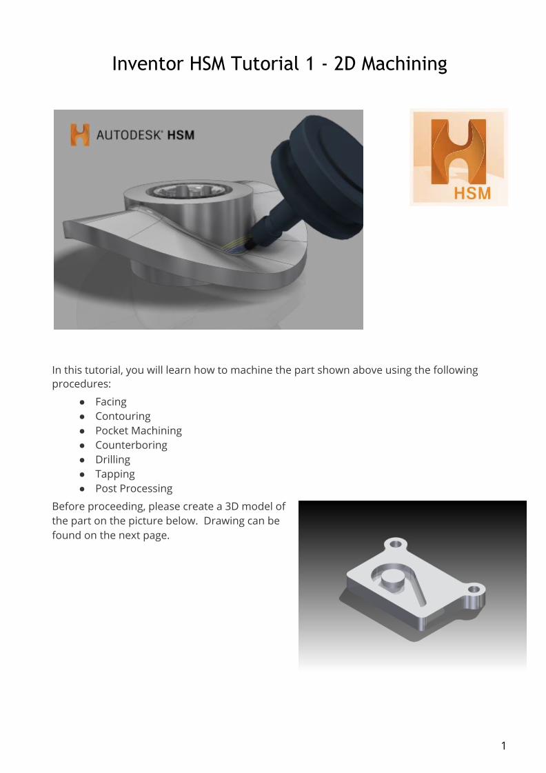
Inventor HSM Tutorial 1 - 2D Machining
In this tutorial, you will learn how to machine the part shown above using the following procedures:
● Facing ● Contouring ● Pocket Machining ● Counterboring ● Drilling ● Tapping ● Post Processing
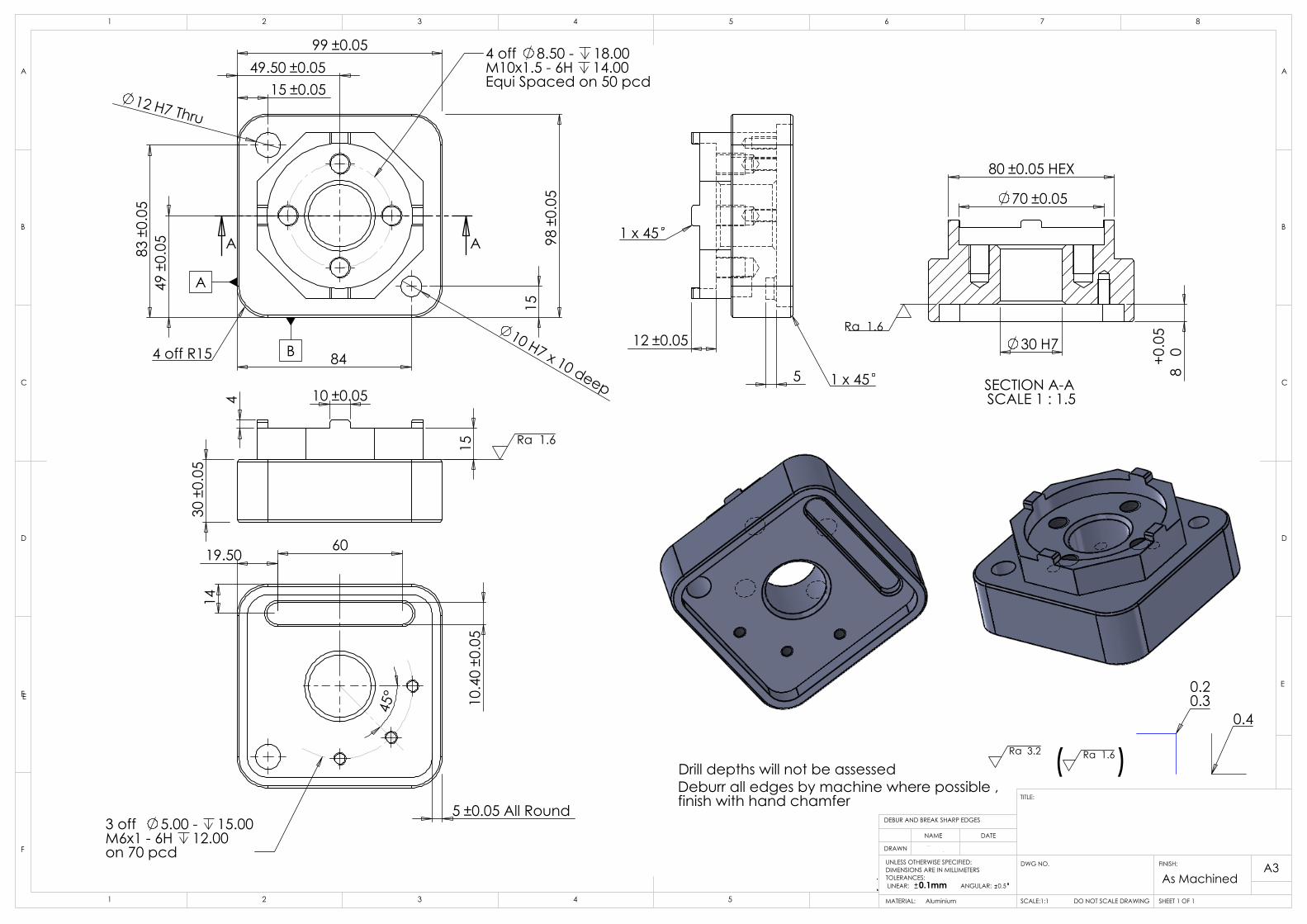
Before proceeding, please create a 3D model of the part on the picture below. Drawing can be found on the next page.
1

2

To Perform Facing
The tutorial begins with a facing operation to clear the top face of the stock and ensure that it is completely flat.
1. On the ribbon, click CAM tab 2D Milling panel Face .
This creates a new facing operation and opens the Operation dialog box where you can edit the individual parameters controlling the toolpath, as well as select the actual geometry to machine.
Each tab on the Operation dialog box is divided into a number of groups. In this tutorial, the necessary settings are changed in each appropriate group as you go along.
Tool tab
1. On the Tool tab, click . 2. This opens the Tool Library where you can select from existing tools in a library or
define a new tool. 3. From the Sample Libraries > Tutorial tool library, select tool #1 - Ø50 mm face.
4. Click to close the Tool Library dialog.
Geometry tab
1. Click the Geometry tab.
The Face strategy automatically detects the size of the stock which is shown as an orange outline on the part.
In this example, the default stock and stock contours work fine and so the stock size need not be specified manually.
Automatically detected stock size
3

Passes tab
The parameters on the Passes tab control how the actual facing toolpath is laid out. The Pass extension setting specifies the distance to extend the passes beyond the machining boundary.
1. Click the Passes tab. 2. Change Pass extension to: 5 mm
Start the Calculation
1. Click at the bottom of the Operation dialog box, or right-click in the graphics window and select OK from the marking menu, to automatically start calculating the toolpath.
The toolpath is now calculated and a preview appears in the graphics window.
By default, the cutting parts of a toolpath are colored in blue, lead moves in green, and rapid moves in yellow. The start and end of the toolpath are indicated by a red and a green triangle respectively.
4

To Contour the Part
Next, run a contouring toolpath along the outside of the part.
1. On the ribbon, click CAM tab 2D Milling panel 2D Contour .
Tool tab
1. On the Tool tab, click . 2. Remember: Tool definitions can be saved in a library or just for the part you work on. In
this example, we will save the tools in the part only. You can always copy the tools to a library at a later time, if you wish to re-use them.
3. Add a new tool with modified dimensions.
4. Click . 5. You can use the default tool type and dimensions (an Ø8 mm flat mill) for this tutorial,
but increase the flute length to be able to cut the entire height of the part (22 mm). 6. Click the Cutter tab. 7. Change Flute length to: 25 mm 8. Attention: If you decide to execute this toolpath on a machine tool, ensure that the tool
number corresponds with the tool position in your tool changer on the machine tool, i.e. that on position 6 you have an 8 mm flat end mill cutter.
9. Click the OK button to create your new tool. 10. Click the Select button to select the tool for your operation and close the Tool Library
dialog.
Feed & Speed Group
Expand the Feed & Speed group and change the following parameters:
1. Spindle speed to: 3000 rpm 2. Cutting feedrate to: 800 mm/min
Attention: If you decide to execute this toolpath on a machine tool, you will also need to set the feed & speed parameters according to the material you are using, and the capabilities of your tool and machine.
Geometry tab
1. Click the Geometry tab. Ensure that the Contour selections button is active so that you can select the outside edge of the part geometry to run the tool around.
5

2. Move the mouse over the bottom front edge. When it highlights, click on it. The bottom contour of the part is chain selected automatically.
3. An arrow then appears near the chained contour indicating the direction of the toolpath. You can reverse the direction of a selected edge by simply clicking the arrow.
4. Do not close the Operation dialog box if you are satisfied with your selection, as that will end the 2D Contour operation. Instead, simply proceed to the next step of this tutorial.
Heights tab
1. Click the Heights tab. A preview of the heights is shown.
Preview of heights: The top orange plane represents the Clearance Height. The second olive green plane represents the Retract Height. The green plane represents the Feed Height. The light blue plane is the Top Height. The dark blue plane is the Bottom Height. To make sure that the tool gets all the way through the stock, lower the bottom height by 1 mm.
6

2. From the Bottom Height drop-down menu, select Model bottom. 3. Change Bottom offset to: -1.0 mm
Observe that the preview plane moves in the graphics window.
Tip: Observe that the various heights can also be adjusted using the mini-toolbar. Simply click the heights plane you wish to change and dynamically drag the arrow manipulator to the value you want. You can also enter the value directly in the mini-toolbar text field.
Start the Calculation
1. Click at the bottom of the Operation dialog box, or right-click in the graphics window and select OK from the marking menu, to automatically start calculating the toolpath.
The toolpath is calculated and shown in the graphics window.
Important: Notice that in the CAM Browser, a new Setup has been created automatically. This is automatically done when creating a new operation before a setup has been created. A setup defines a number of settings used in all the operations contained within the setup. For example, the WCS can be changed in the setup.
7

To Machine the Pocket
The next operation is to machine the pocket with the central circular boss on the top surface of the part.
1. On the ribbon, click CAM tab 2D Milling panel 2D Pocket .
Tool tab
1. On the Tool tab, click the button and select the tool #2 - Ø8 mm flat from the library.
2. Click to close the Tool Library dialog.
Geometry tab
1. Click the Geometry tab. The contours of the pocket to be cleared are selected here. 2. Click anywhere on the face at the bottom of the pocket.
3. 4. 5. Note: Selecting faces for 2D geometry automatically uses all edges of the face for the
contours. However, if two adjacent faces are selected, the edges they share are not included in the selection.
Heights tab
1. By default, the 2D Pocket operation machines from the top of the stock to the level of the selected contours. This is exactly what is needed in this operation, so there is no need to change any heights.
8

Passes tab
1. Click the Passes tab. 2. This group of settings controls how the 2D pocket toolpath is calculated. To clear out the
pocket, the toolpath is generated in a number of Z levels, starting from the top of the stock and going down in steps of 2 mm to the bottom of the pocket.
3. Enable the Multiple Depths check box. 4. Change Maximum roughing stepdown to: 2.0 mm 5. Change Finishing stepdowns to: 1 6. We do not want to leave any stock in this operation, and since this is a roughing
operation, the default is to leave stock. 7. Disable the Stock to Leave check box.
Start the Calculation
1. Click at the bottom of the Operation dialog box, or right-click in the graphics window and select OK from the marking menu, to automatically start calculating the toolpath.
The toolpath is now calculated and shown in the graphics window.
9

To Machine the Counterbores
The next step is to machine the two counterbores at the top left and right corners of the part.
1. On the ribbon, click CAM tab 2D Milling panel Bore .
Tool tab
1. On the Tool tab, click the button and select the tool #2 - Ø8 mm flatfrom the library.
2. Click to close the Tool Library dialog.
Geometry tab
1. Click the Geometry tab. The Circular face selections button should be active. Select the cylindrical faces of the two holes with the largest diameter at the top corners of the part.
2. If necessary, zoom in and click anywhere on the cylindrical surface of the upper large hole.
3. Do the same to select the other hole in the opposite corner.
Passes tab
10

1. Click the Passes tab. Here we control how the helix toolpath is calculated. 2. Change Pitch to: 2.0 mm
Start the Calculation
1. Click at the bottom of the Operation dialog box, or right-click in the graphics window and select OK from the marking menu, to automatically start calculating the toolpath.
The toolpath is now calculated and shown in the graphics window.
11

To Drill Holes
The next step is to drill the two small holes at the top left and right corners of the work piece.
1. On the ribbon, click CAM tab Drilling panel Drill .
Tool tab
Change the default tool.
1. On the Tool tab, click the button.
2. Click the button. 3. This procedure creates a tool with default dimensions and cutting data. The default is a
Ø10 mm drill. We will use most of the defaults, but change some of the cutting parameters a bit.
4. Click the Cutter tab. 5. Change Type to Drill by selecting it from the drop-down menu. 6. Change Diameter to 5 mm. 7. Click the OK button to create your new tool. 8. Click the Select button to select the tool for your operation and close the Tool Library
dialog.
Geometry tab
1. Click the Geometry tab. Ensure that Selected faces is selected from the Hole mode: drop-down menu and that the Hole faces selection button is active.
2. Zoom in, and select the cylindrical face of the smaller diameter hole at the top left corner of the part.
12

3. Enable the Select same diameter check box. Doing so automatically selects the identically sized small hole at the top right of the part.
Heights tab
1. Click the Heights tab and enable the Drill tip through bottom check box. 2. Change Break-through depth to: 1 mm
Cycle tab
1. Click the Cycle tab. 2. Select Chip breaking - partial retract from the Cycle type: drop-down menu.
Start the Calculation
1. Click at the bottom of the Operation dialog box, or right-click in the graphics window and select OK from the marking menu, to automatically start calculating the toolpath.
13

To Tap Holes
A tapping operation differs only from a drilling operation in the type of cycle chosen from the Cycle tab. To simplify this step of the operation, we will just copy the existing drilling toolpath and edit it to create the new tapping toolpath.
1. In the CAM Browser, right-click on the Drill1 node. (Do not be concerned if your Drill node appears with a number other than Drill1.)
2. Select Duplicate from the pop-up context menu. This creates a copy of the operation below the original one.
3. Left-click on the new operation (Copy of Drill1). 4. Enter a new name, such as Tapping M6 and press Enter. 5. Next, you edit the tool and parameters. 6. Right-click on the operation Tapping M6. 7. Select Edit from the pop-up context menu.
Tool tab
Create and select a new tapping tool.
1. On the Tool tab, click the button to open the Tool Library.
2. Click the button. 3. On the General tab, change Number to 8. 4. On the Cutter tab, change Type to Tap (Right Hand). 5. Change Diameter to 6 mm. 6. Change Flute length to 15 mm. 7. On the Feed & Speed tab, change Spindle speed to 400 rpm. 8. Click the OK button to create your new tool. 9. Click the Select button to select the tool for your operation and close the Tool Library
dialog.
Important: If you want to run this toolpath on your machine tool, you may also need to set the Pitch parameter on the Cutter tab, as well as adjust the feed and speed parameters. The correct values can be found in the tool manufacturer's catalog.
Cycle tab
Now, make this a tapping cycle instead of a drilling cycle.
1. Click the Cycle tab and select Tapping from the Cycle type: drop-down menu.
Start the Calculation
14

1. Click at the bottom of the Operation dialog box, or right-click in the graphics window and select OK from the marking menu, to calculate the toolpath. The resulting toolpath should look like this:
You have now completed all the machining strategies for this part. Continue to To Post Process the Toolpaths to finish the tutorial.
To Post Process the Toolpaths
In this final step of the tutorial, all toolpaths are post processed to produce the NC-code to be used by the machine tools. Before starting the post processing, it is good practice to regenerate all toolpaths and then simulate them. Doing so enables you to spot any errors in the toolpaths and rectify them.
1. Start by clicking Setup1 at the top of the CAM Browser.
2. On the ribbon, click CAM tab Toolpath panel Generate . 3. You may receive a dialog box message that the selected operation is already valid. This
means that your toolpaths are good. You can click Yes to optionally regenerate them, or click No to leave them untouched and exit the dialog box.
4. Now, click CAM tab Toolpath panel Simulate . 5. Tip: As an alternative, you can also right-click on the Setup folder in the CAM Browser
and select Simulate (All) from the pop-up context menu. 6. The Simulation player is displayed in the graphics window.
7. 8. 9. Click the Play button on the Simulation player to playback the defined toolpaths. 10. When the simulation is complete, click the Close button in the Simulation dialog box, or
right-click in the graphics window and select Close from the marking menu.
15

11. Next, click CAM tab Toolpath panel Post Process . 12. The Post Process dialog box is displayed. 13. Tip: As an alternative, you can also right-click on the Setup folder in the CAM Browser
and select Post Process (All) from the pop-up context menu. 14. Select heidenhain.cps - Generic Heidenhain from the Post Configuration drop-down
menu. 15. Accept the default output folder or choose another. 16. Accept the default program name/number or provide another. 17. Start the post processor by clicking the Post button. 18. Click the Save button. 19. Because the Open NC file in editor check box is enabled by default in the Post
Process dialog box, the post processed file is automatically loaded into Inventor HSM Edit.
From the editor you can edit, inspect, and transfer your NC program to your CNC machine. The editor provides a number of CNC code-specific functions including line numbering/renumbering, XYZ range finder, and file comparison. The editor also features a DNC link for reliable RS-232 communications with a variety of CNC controls.
Remember: You can also post process individual operations by right-clicking the operation in the CAM Browser, and selecting Post Process from the pop-up context menu.
Congratulations! You have completed this tutorial.
16
98±0
.05
99 ±0.05
12 H7 Thru
10 H7 x 10 deep
49.50 ±0.05
49±0
.05
15 ±0.05
83±0
.05
15
84
A A
4 off 8.50 - 18.00M10x1.5 - 6H 14.00Equi Spaced on 50 pcd
4 off R15 B
A
12 ±0.05
5
1 x 45
1 x 45
30±0
.05
15
4 10 ±0.05
Ra 1.6
5 ±0.05 All Round
60
14
19.50
10.4
0±0
.05
45°
3 off 5.00 - 15.00M6x1 - 6H 12.00 on 70 pcd
70 ±0.05
80 ±0.05 HEX
80+0.0
5
30 H7
SECTION A-A SCALE 1 : 1.5
Ra 1.6
0.20.3
0.4
Drill depths will not be assessedDeburr all edges by machine where possible ,finish with hand chamfer
( )Ra 3.2 Ra 1.6
D
E
F
C
1 2 3 4
B
A
321 5
C
D
4 6 7 8
A
B
A3
SHEET 1 OF 1SCALE:1:1
DWG NO.
TITLE:
DO NOT SCALE DRAWINGMATERIAL:
DATE
DEBUR AND BREAK SHARP EDGES
FINISH:UNLESS OTHERWISE SPECIFIED:DIMENSIONS ARE IN MILLIMETERSTOLERANCES: LINEAR: 0.1mm ANGULAR: 0.5
DRAWN
NAME
5
EE
Ian Thompson
Aluminium
As MachinedWSCUKPH - 2012
Worldskills UK CNC MillingPassive Heat 2012

WorldSkills UK, CNC Milling
Marking Scheme Overview
The marking scheme for the CNC Milling competition is broken down into 4 main areas of inspection and
marking.
1. Primary Dimensions Measured Objectively (Yes, it’s in tolerance / No, it’s not in tolerance)
Tight tolerance dimensions range between ±0.01mm and ±0.05mm
Including H7 bore holes that are not standard reaming sizes
There are between 13 – 17 of these dimensions on the model
These dimensions account for about 50% of the project
2. Secondary Dimensions Measured Objectively (Yes, it’s in tolerance / No, it’s not in tolerance)
These dimensions have a tolerance of ±0.1mm
Including H7 holes that are standard reaming sizes and tapped holes
There are between 13 – 17 of these dimensions on the model
These dimensions account for about 30% of the project
3. Surface Finish Measured Objectively (Yes, it’s in tolerance / No, it’s not in tolerance)
Looking at a surface finish of 0.8Ra
There is usually 2 or 3 surface finish markers on the drawing
There is also a mark for only using one of piece of material
These dimensions account for about 10% of the project
4. Conformity to Drawing Measured Subjectively (Industry Judges give a rating between 1 – 10 on how accurate
it is to given criteria)
Side 1 Complete – are all drawn features present and in correct position
Side 2 Complete – are all drawn features present and in correct position
Machined Chamfers – all edges that can be reached by a chamfer mill must be machined
Hand Chamfers – all edge / corners that cannot be reached by a chamfer mill are
blended in to the machined chamfer
These dimensions account for about 10% of the project