inverse identification of the bending stiffness of a braided
TRANSCRIPT

ECCOMAS Congress 2016VII European Congress on Computational Methods in Applied Sciences and Engineering
M. Papadrakakis, V. Papadopoulos, G. Stefanou, V. Plevris (eds.)Crete Island, Greece, 5–10 June 2016
INVERSE IDENTIFICATION OF THE BENDING STIFFNESS OF ABRAIDED POLYETHYLENE TWINE SUBJECT TO LARGE
DEFORMATION: APPLICATION TO THE IDENTIFICATION OF THEMESH OPENING RIGIDITY OF FISHING NETS.
B. Morvan1−2, G. Bles2, N. Dumergue1, and D. Priour1
1 IFREMERPlouzane, France
e-mail: {barthelemy.morvan, nicolas.dumergue, daniel.priour}@ifremer.fr
2 ENSTA BretagneFRE CNRS 3744
IRDLF-29200 Brest, France
e-mail: [email protected]
Keywords: Numerical model, experiments, braided twine, mesh opening rigidity, large defor-mation.
Abstract. The evaluation of the mesh opening stiffness of fishing nets is an important issue inassessing the selectivity of trawls. It appeared that a larger bending rigidity of twines decreasesthe mesh opening and could reduce the escapement of fish. Nevertheless, netting structure iscomplex. A netting is made up of braided twines made of polyethylene or polyamide. Thesetwines are tied with non-symmetrical knots. Thus, these assemblies develop contact-frictioninteractions. Moreover, the netting can be subject to large deformation. In this study, we inves-tigate the responses of netting samples to different types of solicitations. Samples are loadedand unloaded with creep and relaxation stages, with different boundary conditions. Then, twomodels have been developed: an analytical model and a finite element model. The last one wasused to assess, with an inverse identification algorithm, the bending stiffness of twines. In thispaper, experimental results and a model for netting structures made up of braided twines arepresented. During dry forming of a composite, for example, the matrix is not present or notactive, and relative sliding can occur between constitutive fibres. So an accurate modelling ofthe mechanical behaviour of fibrous material is necessary. This study offers experimental datawhich could permit to improve current models of contact-friction interactions [4], to validatemodels for large deformation analysis of fibrous materials [1] on a new experimental case, thento improve the evaluation of the mesh opening stiffness of a fishing net.
1
B. Morvan, G. Bles, N. Dumergue and D. Priour
1 INTRODUCTION
Twines used in the manufacture of netting materials for trawl codends tend to be stiffer.This increased stiffness affects the mesh opening in fishing gears, and thus the ability of fishto escape. The strong influence of the codend on trawl selectivity has been demonstrated [15].Moreover, previous studies have shown how mesh rigidity to opening affects the mechanicalbehaviour, and thus the selectivity of codends ([5], [16]). However, the mesh opening stiffnessis quite difficult to evaluate. In fact, it depends on its definition and on the theoretical modelof the netting. Generally, to assess the mesh opening stiffness, we consider that a mesh sidemust have the same behaviour as a beam ([16], [9], [12], [13]). With this theoretical model, itappears that the bending rigidity EI of the beam represents the mesh opening stiffness. O´ Neilldemonstrated how an increase in twine bending stiffness reduces the diameter of the codendand so the mesh opening. In addition, Herrmann [5] reported that an increase in twine bendingstiffness could lead to a reduction in selectivity. Likewise, Moderhak [7] theoretically demon-strated how changes in mesh size and mesh opening stiffness can impact the shape of a codendand its selectivity.
As far as the authors know, the first method implemented so far for the assessment of thisstiffness was presented by Sala [16]. The method uses a prototype on which netting panels aremounted and deformed. It incorporates four tension load cells and four stepping motors andit is designed so that all twines of the netting panel have the same deformation. The bendingstiffness of the netting twine is estimated from the data of forces and deformation using thebeam theory. However, the prototype uses a relatively expensive and high-tech device to ensurethe uniform deformation of the netting panel.
Alternative methods exist: Priour and Cognard [14] assumed that the twine bending stiff-ness could be given by the stiffness of a simple cantilever beam whose deformation equals theobserved deformation of a netting panel subject to out-of-plan bending. However, the methoddoes not take into account the effect of knots and requires a sample of close mesh netting. De laPrada and Gonzalez [12] offered a simple uniaxial experimental set-up, which stretches a nettingsample in the T-direction of the meshes while leaving free its deformation in the N-direction.Nevertheless, they assumed that the deformation is identical in all meshes of the sample. Thisassumption is probably too strong because the panel is held in the vertical position during theexperiment, so forces and deformation supported by meshes at the top of the panel are higherthan those supported at the bottom due to gravity.
The final aim of this study is to propose a simple methodology to assess the mesh openingstiffness of fishing nets. This methodology has to be based on a simple experimental plan,which does not require expensive devices, to be easily used in laboratories and in the fishingindustry.
In this paper, we investigate the responses of netting samples to different types of solici-tations; samples are loaded and unloaded with creep and relaxation stages, with two differentboundary conditions. Then, two models have been developed: an analytical model and a finiteelement model. The last one allows the simulation of the netting without uniform deformation.These models were used to assess, with an inverse identification algorithm, the bending stiffnessof mesh sides. In this paper, experimental results and models for netting structures made up ofbraided twines are presented.
2

B. Morvan, G. Bles, N. Dumergue and D. Priour
2 MATERIAL AND EXPERIMENTAL METHOD
2.1 Netting
The netting materials specifications (fibre type, twine construction) were selected accordingto the netting commonly used in trawl codends.
In this paper, we investigate a single twine netting made up of polyethylene (PE). This twineis made up of a core and a sheath (Fig. 1). The core and the sheath are composed of 20 and 64fibres respectively. In the core, fibres are twisted, whereas in the sheath 16 threads made up of4 fibres are braided. The linear density of the twine is 5590.4 10−6 ± 10.6 10−6 kg.m−1, thatis 5590.4 ± 10.6 tex. The diameter of the fibres, measured with a digital microscope, is 302.1µm. The diameter of the twine is 3.14± 0.01mm. The pitch of the braided sheath, which is thelongitudinal distance required for one revolution of a thread around the twine, is 26.12 ±0.62mm.
Figure 1: Left: single twine netting made up of polyethylene. Right: the braided sheath.
Figure 2: Left: mesh side in a single twine netting made up of polyethylene braided twines. Right: scheme of theknot.
Each 4x10 mesh netting panel was subject to a pretension step: each sample was loaded intensile with 392.4 kg in the N-direction during 30 minutes.
In order to define the input data of models, the sample characteristics are obtained:
• The mass m of the netting panel is measured using electronic scale.
• The characteristic length of the netting mesh sides is obtained from the mean value ofsome mesh side lengths measured with a caliper. The length of the mesh side is 40 mm.
• The diameter of the beam elements is calculated so that the mass of the model of thenetting panel is equal to the mass of the real one. The material density of high-densitypolyethylene used for the calculation of the diameter is 950 kg.m−3.
3

B. Morvan, G. Bles, N. Dumergue and D. Priour
• The initial position of the netting panel (i.e. the position at rest) is derived from the lengthand the width of the panel at rest. The panel position at rest is performed by vibrating ahorizontal plane where the netting panel is put down free of load, until a stable positionis reached. Then, the dimensions (width Wpanel0, length Lpanel0) of the netting panelare measured and the mesh angle α0 (angle between a mesh side and the N-direction) isderived with a simple cosinus equation using the characteristic length of the mesh sides(Fig. 3).
Figure 3: The dimensionsWpanel0 andLpanel0 of the netting panel allow the mesh angle α0 at rest to be calculated.
For the study, it is convenient to define some parameters. First, the T-direction and the N-direction in a mesh of the netting have been defined in [6]. The two directions are definedrelatively to the knot orientation (Fig. 2 and 4).
Figure 4: Definition of the N-direction and of the T-direction, and definition of the parameters LN , LT and Lms
in a diamond netting mesh.
4

B. Morvan, G. Bles, N. Dumergue and D. Priour
Then, we can define, in one mesh, the distances LN and LT between opposite knots, in theN-direction and the T-direction respectively. Lms is the length of the mesh side at rest.
To work with dimensionless parameters which do not depend on the mesh side length, weintroduce the openings oN and oT in the N-direction and the T-direction respectively. Theopening oi, in the direction i, is the ratio of the distance Li by the mesh side length Lms (Eq. 1).
oi =LiLms
(1)
2.2 Evaluation of the axial stiffness
Tensile tests have been performed on a LR5Kplus tensile testing machine to evaluate the axialstiffness of twines constituting the studied fishing nets. Because of the complex visco-elasto-plastic behaviour of the polyethylene, it is not straightforward to evaluate the axial stiffnessof the instantaneous elasticity. We proposed to assess this stiffness by measuring the moduli ofshort-time behaviour according to [2]. G. Bles [2] noted that the measurements after relaxationsand creeps and those of the initial modulus were in agreement and provided a characteristicevolution of the modulus. In our study, the strain rate was 2.10−4 s−1 and the load at thebeginning of the relaxation stages increased from 100 to 900 N , by 100 N . The duration of theeight relaxation stages was 15 minutes.
We calculated the moduli of short-time behaviour by calculating the slope at the beginningof each load step, just after a relaxation stage (Fig. 5). The evolution of the moduli with thelogarithmic strain in the case of the studied braided twine is shown in figure 5. For a smalllogarithmic strain (< 0.055), we will suppose that the modulus of short-time behaviour, whichmeans the axial stiffness, is inferior to 14000 N .
Figure 5: Left: the black line presents the load as a function of the logarithmic strain, and the blue segmentsindicate the slope (short-time modulus) just after each relaxation stage. Right: evolution of the short-time modulus,obtained with the slopes in the figure on the left.
2.3 Experiments
Two types of experiments were performed: a tensile test, on a classical testing machine, anda suspending test of the same type as [11].
5

B. Morvan, G. Bles, N. Dumergue and D. Priour
2.3.1 Tensile test
In the first type, measurements were performed on a LR5Kplus tensile testing machine,with a 250 N load cell, of the company Lloyd instruments. The uniaxial tension tests werecontrolled by the jaw displacement. The relaxation stages were performed by blocking the jawmovement. A LASERSCAN 200 non-contacting extensometer (Lloyd instruments) allowed themeasurement of the height of the mesh in the middle of the sample (Fig 6).
Concerning the load, we measured the sum of the effects of the displacement, the weightof the netting panel and the weight of the device which allowed the fixation of the sample. Wedefined the loads FmN and FmT as the loads applied on one mesh in the N-direction and the T-direction respectively. So, knowing the load F applied on the netting panel, the weight Ppanel ofthe sample and the weight Pdevice of the device, we calculated the force by mesh FmT appliedon the mesh in the middle of the netting sample:
FmT =F − Ppanel
2− Pdevice
4(2)
Figure 6: Plan (left) and photograph (right) of the experimental set up of the tensile test.
6

B. Morvan, G. Bles, N. Dumergue and D. Priour
2.3.2 Suspending test
In the second type of experiment, the panel was suspended from one of its ends and wassubject to its own weight and to forces applied on the four nodes at the bottom (Fig. 7).
Figure 7: Experimental set up plan of the suspending test. A panel is suspended from one of its ends and is subjectto its own weight and to forces applied on its bottom end.
Because of the possible variation in the results, 10 samples of 4 x 10 mesh netting panelswere tested in the same conditions and loadings.
When a panel was suspended, the positions of all the nodes of the netting panel were mea-sured. The use of a camera with a software designed and implemented in the laboratory allowedthe recording of pictures with a chosen frequency. Note that the software allowed the applica-tion of optical corrections. Then, targets defined by the user on the first picture were identifiedin all the pictures. So the displacements of all these targets were measured during the recording.The height of the netting panel Lpanel is measured using the position of the uppermost knot andthe position of the lowermost knot.
3 EXPERIMENTAL RESULTS
3.1 Tensile test
Results of a tensile test are shown on figures 8 and 9. A load and unload cycle inter-rupted by several relaxation stages was imposed. The controlled jaw displacement rate was100 mm.min−1. The duration of the 9 relaxation stages was 15 minutes.
Figure 10 presents the result of a cyclic tensile test on a double twine netting sample.
7

B. Morvan, G. Bles, N. Dumergue and D. Priour
Figure 8: Result of a tensile test including relaxation stages of 15 minutes. Above: evolution of the opening in theT-direction of the mesh in the middle of the netting panel. Below: evolution of the force by mesh FmT applied onthe mesh in the middle of the panel.
3.2 Suspending test
During suspending tests, different steps were performed: netting panels were submitted toforces added at the bottom, one after another, of 1.3, 3.257, 7.18 and 11.1 N . For each differentlevel of solicitation, there was a creep period of 30 min. Figure 11 shows the mean value (±standard deviation) of the heights Lpanel measured on the 10 suspended netting samples.
8

B. Morvan, G. Bles, N. Dumergue and D. Priour
Figure 9: Result of a tensile test including relaxation stages.
Figure 10: Result of a cyclic tensile test on a double twine netting sample.
4 NUMERICAL METHODS
4.1 Analytical model
An analytical model based on the beam theory and allowing large rotations is proposed tosimulate the tensile test, assuming that the load applied on the mesh in the middle of the nettingpanel is supposed to be uniaxial, only in the T-direction. The notations used are defined in figure12.
First, the bending moment M is related to the curvature as follows:
9

B. Morvan, G. Bles, N. Dumergue and D. Priour
Figure 11: Evolution of the mean value (± standard deviation) of the heights Lpanel measured on the 10 suspendednetting samples.
Figure 12: Left: application of a load FmT on a mesh. Right: kinematic of the twine between the points E and I .
M = EIdα
ds(3)
where EI is the bending stiffness, s is the curvilinear abscissa, α is the mesh angle, and dαds
is the curvature.The bending moment is given by:
M =FmT
2(xI − x) (4)
10

B. Morvan, G. Bles, N. Dumergue and D. Priour
along the center line of the beam.The curvature is a function of y(x) as follows:
(dα
ds) = cos2(α)y′′(x)
1√1 + [y′(x)]2
=y′′(x)
[1 + [y′(x)]2]3/2(5)
By using relations 3, 4 and 5, the following expression is obtained:
∀x ∈ [0;xI ]FmT
2(xI − x) = EI
y′′(x)
[1 + [y′(x)]2]3/2(6)
The boundary conditions are:
y(x = 0) = 0 (7)
α(x = 0) = α0 ⇔ y′(x = 0) = tan(α0) (8)
The length of the mesh sides is assumed to be constant:
∀t ∈ R+ Lms = Lms0 (9)
∫ I
Eds =
∫ I0
E0
ds =Lms0
2(10)
Lms02
=∫ xI
0
δs
δxdx =
∫ xI
0
√1 + [y′(x)]2 dx (11)
To work with dimensionless parameters, x and y are defined by:
x =2x
Lms0y =
2y
Lms0(12)
And u is defined by:
∀x ∈ [0;xI ] u(x) = y′(x) (13)
Using equations 12 and 13, relations 6, 8 and 11 become 14, 15 and 16 respectively.
∀x ∈ [0; xI ]FmT
2(Lms0
2)2(xI − x) = EI
u′(x)
[1 + [u(x)]2]3/2(14)
11
B. Morvan, G. Bles, N. Dumergue and D. Priour
u(x = 0) = tan(α0) (15)
∫ xI
0
√1 + [u(x)]2 dx = 1 (16)
The solutions of the differential equation 14 are:
∀x ∈ [0; xI ]FmT
2EI
Lms02
4x[xI −
x
2] =
u(x)√1 + [u(x)]2
+K (17)
where K ∈ R.Using relation 15 with relation 17, we obtain:
∀x ∈ [0; xI ]FmT
2EI
Lms02
4x[xI −
x
2] =
u(x)√1 + [u(x)]2
− tan(α0)√1 + tan2(α0)
(18)
To simplify the equation, we defined v by:
∀x ∈ [0; xI ] v(x) =u(x)√
1 + [u(x)]2(19)
So u can also be defined by:
∀x ∈ [0; xI ] u(x) =v(x)√
1− [v(x)]2(20)
where v ∈]− 1; 1[.Then relation 18 leads to:
∀x ∈ [0; xI ] v(x) =FmT
2EI
Lms02
4x[xI −
x
2] + sin(α0) (21)
By using relations 20, 21 and 16, the value of xI can be evaluated by an iterative algorithm(e.g. dichotomy algorithm).
Using the relations 12 and 13, y becomes:
∀x ∈ [0; xI ] y(x) =∫ x
0u(x) dx (22)
So yI can be calculated by:
yI =∫ xI
0u(x) dx (23)
Finally, the displacement of the half mesh side, and so the opening of the mesh in the middleof the netting panel during the tensile test, submitted to a tensile force FmT , can be calculatedby relations 20, 21 and 23.
12

B. Morvan, G. Bles, N. Dumergue and D. Priour
4.2 Finite element model
The mechanical behaviour of the studied netting was modeled using the Abaqus Standardfinite element code. A mesh side was assumed to behave like a Timoshenko beam. In Abaqus,we model a mesh side with a planar beam that uses linear interpolation and a 2D hybrid formu-lation (B21H type in Abaqus). Timoshenko beams allow for transverse shear deformation andcan be subject to large axial strains. Hybrid beam element types are used for geometrically non-linear analysis when the beam undergoes large rotations. In this study, we modeled a mesh sidewith 20 B21H elements. The shear modulus was supposed to be very high so that the transverseshear deformation was not taken into account. The axial stiffness EA of the beam elements wasdetermined using the results presented in figure 5.
4.3 Inverse identification methods
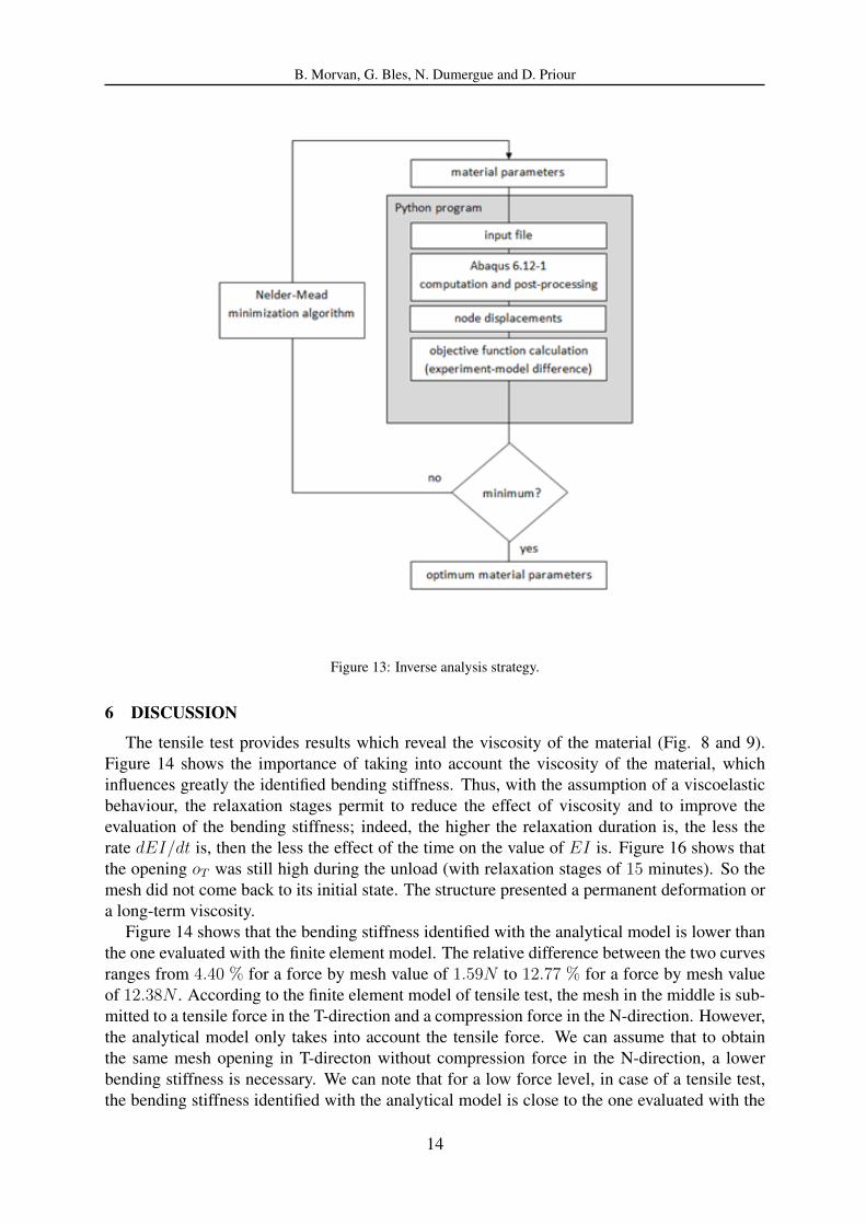
The global scheme for the identification of one mechanical parameter, here the bendingstiffness, is presented on Fig. 13.
In case of the tensile test, the objective function was the difference between the experimen-tal and the numerical height of the mesh in the middle of the netting panel. In case of thesuspending tests, the objective function was calculated by using two different methods: first,the objective function was the mean distance between the coordinates of the experimental andthe numerical knots; then, the objective function was the difference between the experimentaland the simulated suspended sample height. There was a difference of 3.5 per cent betweenthe bending stiffness identified using the measured coordinates of all the knots and the bendingstiffness evaluated using the height of the netting panel. Thus, it was decided to identify theparameter with only the height of the netting sample.
The optimization of the search of the parameter EI is performed with the Nelder-Mead (ordownhill simplex) algorithm proposed by John Nelder and Roger Mead ([8]).
This algorithm is used within the Python library SciPy, which contains an optimization mod-ule. The convergence is usually reached after about ten loop iterations of the Nelder-Meadalgorithm.
5 NUMERICAL RESULTS
5.1 Tensile test
Using the experimental results and the identification method presented previously, we iden-tified the bending stiffness EI of braided twines constituting the netting sample. The evolutionof the bending stiffness EI is presented on figure 14. The evolutions of this parameter dur-ing the whole test, including relaxation stages, identified with the finite element model and theanalytical model, are presented.
Figures 15 and 16 show, respectively, the influence of the force by mesh in the T-directionand the influence of the opening oT on the bending stiffness. For these two figures, the bendingstiffness was identified using the finite element model at the begining (0 min) and at the end (15min) of the relaxation stages.
5.2 Suspending tests
The identified evolution of the bending stiffness, in the case of suspending tests, is presentedon figure 17. As previously described, the identifications of the bending stiffness have beencarried out using results of suspending tests on 10 netting samples.
13
B. Morvan, G. Bles, N. Dumergue and D. Priour
Figure 13: Inverse analysis strategy.
6 DISCUSSION
The tensile test provides results which reveal the viscosity of the material (Fig. 8 and 9).Figure 14 shows the importance of taking into account the viscosity of the material, whichinfluences greatly the identified bending stiffness. Thus, with the assumption of a viscoelasticbehaviour, the relaxation stages permit to reduce the effect of viscosity and to improve theevaluation of the bending stiffness; indeed, the higher the relaxation duration is, the less therate dEI/dt is, then the less the effect of the time on the value of EI is. Figure 16 shows thatthe opening oT was still high during the unload (with relaxation stages of 15 minutes). So themesh did not come back to its initial state. The structure presented a permanent deformation ora long-term viscosity.
Figure 14 shows that the bending stiffness identified with the analytical model is lower thanthe one evaluated with the finite element model. The relative difference between the two curvesranges from 4.40 % for a force by mesh value of 1.59N to 12.77 % for a force by mesh valueof 12.38N . According to the finite element model of tensile test, the mesh in the middle is sub-mitted to a tensile force in the T-direction and a compression force in the N-direction. However,the analytical model only takes into account the tensile force. We can assume that to obtainthe same mesh opening in T-directon without compression force in the N-direction, a lowerbending stiffness is necessary. We can note that for a low force level, in case of a tensile test,the bending stiffness identified with the analytical model is close to the one evaluated with the
14

B. Morvan, G. Bles, N. Dumergue and D. Priour
Figure 14: Tensile test. Evolution of the bending stiffness EI , identified with the finite element model (’⊕’, blackline) and the analytical model (’×’, blue line).
Figure 15: Tensile test. Evolution of the bending stiffness EI , identified using the finite element model at 0 minute(’⊕’, black line) and at 15 minutes (’×’, blue line) of each relaxation stage, as a function of the applied load FmT .
finite element model.Figures 15 and 16 show the evolution of the identified bending stiffness as a function of the
force applied on the mesh FmT and as a function of the opening oT respectively. We can notethat the variation of the parameter EI during the test is smaller when it has been calculatedat the end of each relaxation step. However, the evolution of FmT (Fig. 8) indicates that thecontribution of the viscosity is not completely relaxed after a relaxation stage of 15 minutes.
When the opening increases (and so the force), the tensile force in mesh sides increases so
15

B. Morvan, G. Bles, N. Dumergue and D. Priour
Figure 16: Tensile test. Evolution of the bending stiffness EI , identified using the finite element model at 0 minute(’⊕’, black line) and at 15 minutes (’×’, blue line) of each relaxation stage, as a function of the opening in theT-direction, oT .
we could suspect that the twine diameter decreases. And a smaller diameter means a smallermoment of inertia I . Thus, we could suspect a decrease of EI when the opening increases. Butfigure 16 shows that EI increases when the opening oT of the mesh increases. It is necessaryto take into account the complexity of the twine structure. When the twine diameter decreases,interactions between fibres (directions) and interactions between the core and the sheath becomedifferent. The complexity of the behaviour was already revealed on figure 5 which showed thatit was not possible to identify a constant Young modulus E.
During the tensile test, the force by mesh at the beginning of relaxation stages ranged from2.40 N to 12.38 N . During suspending tests, netting panels were submitted to forces by meshadded at the bottom ranging from 0.3235 N to 2.775 N . The force by mesh applied on theuppermost meshes was higher and ranged from 0.46 N to 2.91 N due to the effect of gravity.The load applied on meshes during suspending tests were only around a quarter of the loadapplied during the tensile test. With this loading level, a smaller opening oT of the mesh isobserved during the suspending test than during the tensile test, therefore a smaller variation ofthe identified bending as presented on figure 17. We can note that the bending stiffness identifiedfor the smallest value of force by mesh with the tensile test is close to the ones identified withthe suspending tests.
The suspending tests on 10 netting samples allow us to calculate the first and third quartiles,and the standard deviation of the bending stiffness (Fig. 17). The standard deviation of thebending stiffness decreases when the load increases, so when the opening of meshes increases.We can remember that each sample was subject to a pretension step (loaded in tensile with392.4 N in the N-direction during 30 minutes). Thus, we can suppose that the decrease of thestandard deviation is not caused by the tightening of knots.
16

B. Morvan, G. Bles, N. Dumergue and D. Priour
Figure 17: Suspending test. Medians of the bending stiffness EI with first and third quartiles (above) and standarddeviation (below) of EI at the begining (20 s) and at the end (30 min) of each creep stage.
7 CONCLUSION
A simple method to evaluate the bending stiffness of braided twines, so the mesh openingstiffness of fishing nets, is presented. In this study, twines were made up of polyethylene.
Two different tests were performed: a tensile test and a suspending test. In case of a tensiletest, a load and unload cycle interrupted by several relaxation stages was imposed. In caseof suspending test, netting panels were submitted to forces added at the bottom, with creepstages. The experimental results show the importance of taking into account the viscosity of thematerial.
Two models based on the beam assumption were developped: an analytical model and a finite
17

B. Morvan, G. Bles, N. Dumergue and D. Priour
element model. The results obtained with these models are close, even if the bending stiffnessidentified with the analytical model, in case of the tensile test, is lower than the bending stiffnessevaluated with the finite element model. The finite element model is more accurate because itmodels the compression force in the N-direction.
The results of the identifications show an evolution of the bending stiffness as a functionof time (viscosity), of the load level and of the mesh opening. To take into account the effectof the structure of the braided twine, one could model the fibres constituting the core and thesheath of each twine, and the interactions between the fibres. This work provides experimentalresults that could be used to study the contact-friction interactions, to develop a model for largedeformation analysis of fibrous material.
Finally, the identification of the bending stiffness EI on suspending test, proposed here, couldbe used as a simple methodology to evaluate the mesh opening stiffness of fishing nets.
ACKNOWLEDGMENT
This research received the support of Region Bretagne under a financing agreement for doc-toral research (no. 13/2.213 747/F).
REFERENCES
[1] P. Badel, E. Vidal-Sall, P. Boisse, Large deformation analysis of fibrous materials usingrate constitutive equations. Computers and Structures, 86, 1164–1175, 2008.
[2] G. Bles, W.K. Nowacki, A. Tourabi, Experimental study of the cyclic visco-elasto-plasticbehaviour of a polyamide fibre strap. International Journal of Solids and Structures, 46,2693–2705, 2009.
[3] M. K. Broadhurst, D. J. Sterling, R. B. Millar, Increasing lateral mesh openings in penaeidtrawls to improve selection and reduce drag. Fisheries Research, 170, 68–75, 2015.
[4] D. Durville, Contact-friction modelling within elastic beam assemblies: an application toknot tightening. Comput Mach, 49, 687–707, 2012.
[5] B. Herrmann, F.G. O’Neill, Theoretical study of the influence of twine thickness on had-dock selectivity in diamond mesh cod-ends. Fisheries research, 80, 221–229, 2006.
[6] ISO, Fishing nets — Netting — Basic terms and definitions. International Standard Or-ganisation, 1107, ISO Geneva, 1974.
[7] W. Moderhak, Influence of twine parameters on the shapes of meshes and T90 codends.International Workshop Methods for the Development and Evaluation of Maritime Tech-nologies(DEMaT’07), ROSTOCK, Germany, 2007.
[8] J.A. Nelder, R. Mead, A Simplex Method for Function Minimization. The ComputerJournal, 7, 308–313, 1965.
[9] F.G. O’Neill, Bending of twines and fibres under tension. Journal of the Textile Institute,93, 1–8, 2002.
[10] F.G. O’Neill, A theoretical study of the factors which influence the measurement of fishingnetting mesh size. Ocean engineering, 30, 2053–2063, 2003.
18

B. Morvan, G. Bles, N. Dumergue and D. Priour
[11] A. de la Prada, M. Gonzales, Nonlinear stiffness models of a net twine to describe mesh re-sistance to opening of flexible net structures. J Engineering for the Maritime Environment,2014.
[12] A. de la Prada, M. Gonzales, Quantifying mesh resistance to opening of netting panels: ex-perimental method, regression models, and parameter estimation strategies. ICES Journalof Marine Science, 2014.
[13] D. Priour, A finite element method for netting: application to fish cages and fishing gears.Springer, 2013.
[14] D. Priour, J.-Y. Cognard, Investigation of methods for the assessment of the flexural stiff-ness of netting panels. 10th International Workshop Methods for the Development andEvaluation of Maritime Technologies (DEMaT’11), SPLIT, Croatie, 2011.
[15] J.H.B. Robertson, P.A.M. Stewart, A comparison of size selection of haddock and whitingby square and diamond mesh codends. J. Cons. Int. Explor. Mer, 44, 148–161, 1988.
[16] A. Sala, F.G. O’Neill, G. Buglioni, A. Lucchetti, V. Palumbo, RJ. Fryer, Experimentalmethod for quantifying resistance to the opening of netting panels. ICES Journal of MarineScience: Journal du Conseil, 64, 1573–1578, 2007.
19