investigate numerical analysis of power lift gate …
TRANSCRIPT

Journal of Analysis and Computation (JAC) (An International Peer Reviewed Journal), www.ijaconline.com, ISSN 0973-2861
Volume - XIV, Issue VII, JULY 2020
Abhijeet S. Salunkhe, Kashinath H. Munde, Ashish R. Pawar 1
INVESTIGATE NUMERICAL ANALYSIS OF POWER LIFT GATE
SPINDLE & SOCKET ASSEMBLY WITH MODIFICATIONS
Abhijeet S. Salunkhe*1, Kashinath H. Munde #1, Ashish R. Pawar#2
*1Post Graduate Scholar, #1Associate Professor, #2Assistant Professor
Mechanical Engineering Department
ABMSP’s Anantrao Pawar College of Engineering & Research, Pune, Maharashtra, India *[email protected]
ABSTRACT- The purpose of this work is to model and simulate the static and dynamic behavior of an electrically
powered lift gate, e.g., the lift gate itself and its drive system. The resulting model is going to be used for
simulation during development of the lift gate control system software. The simulation model has to be
based on physical equations and be adjustable to different lift gate dimensions and different actuators.
After adaptation to ambient conditions the model is verified and validated. The model should simulate
both static and dynamic behavior of the power lift gate system. Thereby, development of the control unit
software can be tested and evaluated without having to apply it on the real system every time or even
when no real system is available. The practical advantage with simulation is mainly that tests can be done
without endangering the hardware. The drive system itself is composed of a spindle that is driven by a
DC-motor over a gear and a spring. When developing the control system, it is convenient to use a
simulation model instead of having to implement it on the system every time. The simulation analytically
describes how the system is behaving. Ansys Workbench is used to build the simulation model.
Verification is done by comparison between physical test data and simulation results.
Keyword - Power lift gate system, Ansys Workbench, Static behavior, dynamic behavior, verification,
physical test
1. INTRODUCTION
The use of electrically-powered drivers to raise and lower automotive trunk lids, lift gates, and engine
hoods is becoming more common. The most common types of trunk lift gates use a brushed DC motor
that responds to commands from control switches in the cabin or switches on a key fob. These drivers
typically have a series of mechanical gears with a mechanical advantage to supply sufficient torque to
move the large mechanical load. This advantage increases the effective torque from the motor and
decreases the rotation speed. A mechanical arm and connected linkage convert the rotation into a force
that is used to open or close the gate.
INVESTIGATE NUMERICAL ANALYSIS OF POWER LIFT GATE SPINDLE & SOCKET ASSEMBLY
WITH MODIFICATIONS
Abhijeet S. Salunkhe, Kashinath H. Munde, Ashish R. Pawar 2
One consideration in the design of the trunk lift is that some users prefer manual operation without
electrical drive. Manually opening or closing the lid when the unpowered motor must be back-driven is
very difficult because of the mechanical advantage of the gear train from the motor to the lifting arm. A
clutch mechanism is typically used to disconnect the motor and some of the gear train from the remaining
mechanism and the lid to make manual operation easier.
To simulate and validate the design of power lift gate socket and spindle assembly. The simulation of PLG
system consists of dynamic and static analysis of the system. In order to make the simulation of PLG
system the Ansys Workbench software is used. For the CAD modeling CATIAV5 software is used.
In the simulation process all types of the non-linearity is considered. In the material data the nonlinear
materials are used, for the contact non linearity the frictional contacts are used and geometrical non-
linearity is also considered. The simulation is performed at room temperature.
In the testing the test rig to be used for the testing. The setup and environment of testing is already
considered in testing. The assumption regarding material and frictions are also considered.
Vehicle lift gates are operated by a variety of power actuators. The most typical systems are electrically
powered with a computer control system executing driver’s command to open and close the lift gate. The
control system has to have enough power to open and close the lift gate in specified time over the range
of environmental conditions, on inclined roads and so on. It also has to be able to reverse the direction of
motion in a short time when an obstacle is found on the way. In order to develop a reliable controller, the
dynamic properties of the system have to be modeled first. The dynamic model can be used not only to
analyze dynamic properties of the system but also to conceive a model based control strategy based on an
inverse dynamics model. The dynamic model of the litigate should include all major contributors
characterizing the dynamics of the litigate: gate geometry and inertia properties, strut mass effects, power
actuator inertia, strut springs and actuator forces, and possibly spindle and DC motor parameters. It should
be possible to include in the model frictional effects at the gate hinges and strut ball joints, as well as all
frictional losses in the powered struts.
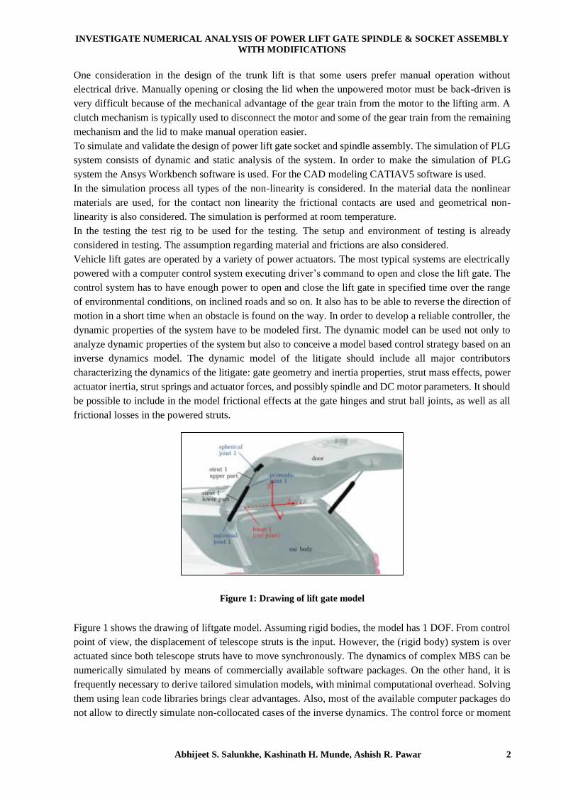
Figure 1: Drawing of lift gate model
Figure 1 shows the drawing of liftgate model. Assuming rigid bodies, the model has 1 DOF. From control
point of view, the displacement of telescope struts is the input. However, the (rigid body) system is over
actuated since both telescope struts have to move synchronously. The dynamics of complex MBS can be
numerically simulated by means of commercially available software packages. On the other hand, it is
frequently necessary to derive tailored simulation models, with minimal computational overhead. Solving
them using lean code libraries brings clear advantages. Also, most of the available computer packages do
not allow to directly simulate non-collocated cases of the inverse dynamics. The control force or moment

Journal of Analysis and Computation (JAC) (An International Peer Reviewed Journal), www.ijaconline.com, ISSN 0973-2861
Volume - XIV, Issue VII, JULY 2020
Abhijeet S. Salunkhe, Kashinath H. Munde, Ashish R. Pawar 3
has to be applied directly at the degree of freedom that is prescribed to follow a desired time trajectory. In
most of the practical applications the actuator used to enforce the so-called program constraint does not
act that way, and quite often the constraint expression itself involves more than one of system generalized
coordinates and velocities.
from its aluminium accomplice. Moreover, the shot composite π joint and its aluminium accomplice
showed that the darted composite π joint shows a greater burden passing on limit with a broad weight
decline. Also, it was exhibited that any extension in the shock opening slack prompts an addition in shock
rotate, similarly as a diminishing in shock hole contact zone, and from now on, a decline in joint strength.
The liftgate is attached to the vehicle body by means of two hinges with aligned axes. To avoid redundant
CONSTRAINTS, the two hinges are modeled by one revolute joint. In a typical arrangement, two struts
support the liftgate on both sides. Although spherical joints are used on each end of the strut, in multibody
system it is prudent to treat one of them as a universal or hook joint, to prevent the axial rotation of the
strut when the friction is not applied. Each strut can be modeled as composed of two cylindrical tubes that
can only translate with respect to each other. Actuator inside of the powered strut can apply a force through
a gear transmission and a lead screw. Mechanical struts can also have preloaded screw installed inside
tubular elements. This is one of possible arrangements of the liftgate mechanism; other configurations are
possible for which the same modeling methodology can be applied.
1.1 PROBLEM STATEMENT
The new PLG spindle socket will satisfy the standards as per customer specification. Also other
requirement considered for the design like variable length, low cost. To check this new design for
optimized shape, material and safety point of view with tensile test and buckling test.
In above PLG system we are considering optimization of socket.
In socket optimization we are focusing on shape optimization and material optimization.
In current system the material for the socket is Steel (SS439).
In material optimization we are using polymer materials such which possesses good strength and mold-
ability.
Disadvantages of Steel material:
• High machining cost.
• Noise level is high in system during Close-Open operation.
• Overall weight is high.
1.2 OBJECTIVES
To check plastic strain and principle stress under tension, it should be within limit as per standards.
To optimize socket by using plastic material.
To check plastic strain and principle stress under tension, it should be within limit as per standards
(5000N).
Record force value at point of failure of component under tension.
To validate the design by physical testing.
2. METHODOLOGY
The literature review regarding the PLG spindle and socket system.
Design of PLG system and deciding boundary conditions according to application and
environmental conditions,

INVESTIGATE NUMERICAL ANALYSIS OF POWER LIFT GATE SPINDLE & SOCKET ASSEMBLY
WITH MODIFICATIONS
Abhijeet S. Salunkhe, Kashinath H. Munde, Ashish R. Pawar 4
Building FEA model in ANSYS workbench and deciding parameters such as materials,
temperature, loading and boundary conditions, contact behavior, meshing quality
Documentation which will include the theory of PLG system, iteration study from raw model to
final model, results discussion, experimental results and test results.
3. NUMERICAL ANALYSIS
These equation sets are the element equations. They are linear if the underlying PDE is linear, and vice
versa. Algebraic equation sets that arise in the steady state problems are solved using numerical linear
algebra methods, while ordinary differential equation sets that arise in the transient problems are solved
by numerical integration using standard techniques such as Euler's method or the Runge-Kutta method.
FEM is best understood from its practical application, known as finite element analysis (FEA). FEA has
applied in engineering is a computational tool for performing engineering analysis. It includes the use of
mesh generation techniques for dividing a complex problem into small elements, as well as the use of
software program coded with FEM algorithm. In applying FEA, the complex problem is usually a physical
system with the underlying physics such as the Euler-Bernoulli beam equation, the heat equation, or the
Navier-Stokes equations expressed in either PDE or integral equations, while the divided small elements
of the complex problem represent different areas in the physical system.
In present research for analysis ANSYS (Analysis System) software is used. Basically, its present FEM
method to solve any problem. Following are steps in detail
1. Geometry
2. Discretization (Meshing)
3. Boundary condition
4. Solve (Solution)
5. Interpretation of results
Fig. 2 CATIA model of specimen
Three-dimensional model of existing specimen was designed in Catia V5 R20 software.
Initially geometry is designed in CATIA software and analysis is performed in ANSYS software. So, in
present research both Steel and Grivory material are selected to study the effect.

Journal of Analysis and Computation (JAC) (An International Peer Reviewed Journal), www.ijaconline.com, ISSN 0973-2861
Volume - XIV, Issue VII, JULY 2020
Abhijeet S. Salunkhe, Kashinath H. Munde, Ashish R. Pawar 5
Table 1- Material properties of structural steel
Table 2- Material properties of Grivory
MESH
ANSYS Meshing is a general-purpose, intelligent, automated high-performance product. It produces the
most appropriate mesh for accurate, efficient Multiphysics solutions. In ANSYS after importing geometry
in module meshing is performed also known as discretization process. In meshing whole component is
breakdown or discretized into small elements to solve finite element equation at nodes. In present
hexahedral mesh is used for analysis. A mesh well suited for a specific analysis can be generated with a
single mouse click for all parts in a model.

INVESTIGATE NUMERICAL ANALYSIS OF POWER LIFT GATE SPINDLE & SOCKET ASSEMBLY
WITH MODIFICATIONS
Abhijeet S. Salunkhe, Kashinath H. Munde, Ashish R. Pawar 6
Fig. 3 CAD of Spindle
Fig. 4 Meshing of Spindle
Fig. 5 Details of the meshing
Contact Status
Fig. 6 Detail of assembly
Journal of Analysis and Computation (JAC) (An International Peer Reviewed Journal), www.ijaconline.com, ISSN 0973-2861
Volume - XIV, Issue VII, JULY 2020
Abhijeet S. Salunkhe, Kashinath H. Munde, Ashish R. Pawar 7
Fig. 7 Boundary condition spindle
In the contact status the frictional and bonded contacts are used. The frictional contacts are given with 0.1
COF.
Boundary Condition
In boundary condition displacement of 1mm along length is applied on ball stud. As in the image shown
below faces of ball stud in yellow shades are selected and displacement is applied at distance of 30mm as
per test specification. Here the Tenon is hold in fixed position.
After application of axial pull force on the ball stud, it will make impact on the ball socket which need to
be evaluated in these boundary conditions
Fig. 8 Applied boundary conditions
Total Deformation
In finite element method the total deformation and directional deformation are general terms irrespective
of software being used. Directional deformation may be place because the displacement of the system in
a very particular axis or user defined direction. Total deformation is that the vector sum of all directional
displacements of the systems.
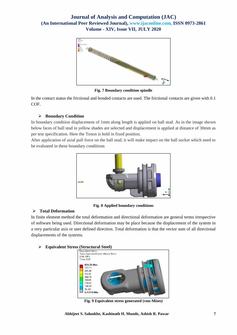
Equivalent Stress (Structural Steel)
Fig. 9 Equivalent stress generated (von-Mises)

INVESTIGATE NUMERICAL ANALYSIS OF POWER LIFT GATE SPINDLE & SOCKET ASSEMBLY
WITH MODIFICATIONS
Abhijeet S. Salunkhe, Kashinath H. Munde, Ashish R. Pawar 8
Equivalent Von-Mises Stress=460MPa
Ultimate Strength=460MPa
Fig. 10 Force reaction
Table 3- Total reaction force
Total force reaction in specimen was 5112.1N
Simulation of socket with Grivory6H1
Geometry
Fig. 11 Geometry inserted in ANSYS Software.
Fig. 12 Details of meshing

Journal of Analysis and Computation (JAC) (An International Peer Reviewed Journal), www.ijaconline.com, ISSN 0973-2861
Volume - XIV, Issue VII, JULY 2020
Abhijeet S. Salunkhe, Kashinath H. Munde, Ashish R. Pawar 9
Fig. 13 Details of applied boundary condition
Fig. 14 Equivalent plastic Strain
Plastic Strain (Tensile region) = 1%
Force at Strain Limit = 5010.8 N
Fig. 15 Principal Stress

INVESTIGATE NUMERICAL ANALYSIS OF POWER LIFT GATE SPINDLE & SOCKET ASSEMBLY
WITH MODIFICATIONS
Abhijeet S. Salunkhe, Kashinath H. Munde, Ashish R. Pawar 10
Max. Principal Stress=290.97MPa
Maximum principle stress shown by software in specimens was 290.97MPa
Force Reaction
Fig. 16 Force reaction
Table 4- Force reaction details
Force =5010.8 N
4. RESULT
The results are shown I below table as per the calculated values comes after in numerical analysis i.e.
ANSYS with the help of analysing the both component in Software.
Table 5- ANSYS values at different orientation
SR.
NO. MATERIAL PARAMETERS FEA RESULT
1
ST
RU
CT
UR
AL
ST
EE
L Equivalent Stress 629.29 MPa
Plastic Strain 0.0427 mm
Max. Principle Stress 458.87 Mpa
2
GR
IVO
RY
HT
V
Equivalent Stress 290.97 Mpa
Plastic Strain 0.0199 mm
Max. Principle Stress 302.74 MPa

Journal of Analysis and Computation (JAC) (An International Peer Reviewed Journal), www.ijaconline.com, ISSN 0973-2861
Volume - XIV, Issue VII, JULY 2020
Abhijeet S. Salunkhe, Kashinath H. Munde, Ashish R. Pawar 11
5. CONCLUSION
In present research ball socket is applied with axial force with steel and polymer material Grivory
HTV.
It is observed from both analysis that force reaction is around 5000N.
So, as observed with polymer material (Grivory HTV) ball socket can sustain force required during
application.

INVESTIGATE NUMERICAL ANALYSIS OF POWER LIFT GATE SPINDLE & SOCKET ASSEMBLY
WITH MODIFICATIONS
Abhijeet S. Salunkhe, Kashinath H. Munde, Ashish R. Pawar 12
REFERENCES
1. Tailored modeling of a vehicle power liftgate avoiding explicit definition of body-fixed reference frames”, Andreas
M ¨uller JKU Johannes Kepler University, Linz, Austria, Krystof P. Jankowski Magna Closures, Novi, MI August
2-5, 2015, Boston, Massachusetts, USA
2. Dynamic and static behavior of an electrically powered lift gate, Daniel Axehill, Carsten Haubenschild, Ralf
Wagner, Department of Electrical Engineering, Linköpings universitet, SE-581 83 Linköping, Sweden, 22 February,
2008
3. Yanfeng Zhang, Zhengong Zhou, and Zhiyong Tan Experimental and Finite Element Research on the Failure
Mechanism of C/C Composite Joint Structures under Out-of-Plane Loading
4. Liberatore V, Ghadimi B, Rosano M, et al. Microstructural analysis of GFRP failure mechanisms after compressive
load and temperature duress. Compos Struct 2018; 203: 875–885.
5. Russo S, Ghadimi B, Lawania K, et al. Residual strength testing in pultruded FRP material under a variety of
temperature cycles and values. Compos Struct 2015; 133: 458–475.
6. Andreas Mueller, Tailored Modeling of a Vehicle Power Liftgate Avoiding Explicit Definition of Body-Fixed
Reference Frames, Conference: ASME 2015 International Computers and Information in Engineering ConferenceAt:
Boston, Massachusetts, USA, August 2015 DOI: 10.1115/DETC2015-47524
7. J. Selig: Geometric Fundamentals of Robotics (Monographs in Computer Science Series), Springer-Verlag New
York, 2005
8. A.A. Shabana: Dynamics of Multibody Systems, 3rd ed., Cambridge University Press, 2005
9. J.J. Uicker, B. Ravani, P.N. Sheth: Matrix Methods in the Design Analysis of Mechanisms and Multibody Systems,
Cambridge University Press, 2013
10. Nezhad HY, Egan B, Merwick F, et al. Bearing damage characteristics of fibre-reinforced countersunk composite
bolted joints subjected to quasi-static shear loading. Compos Struct 2017; 166: 184–192.
11. ASTM D5961/D5961M-13. Standard test method for bearing response of polymer matrix composite laminates.
West Conshohocken: ASTM International, 2013.
12. ENGINEER MANUAL, US Army Corps Of Engineers ENGINEERING AND DESIGN, Mechanical and
Electrical Design for Lock and Dam Operating Equipment, EM 1110-2-2610 30 June 2013
13. Kedar Madhusudan Kulkarni, Design and Development of Lift without Electricity, IJSRD - International Journal
for Scientific Research & Development| Vol. 8, Issue 1, 2020 | ISSN (online): 2321-0613
14. B. Bolund, H. Bernhoff, M. Leijon, Flywheel energy and power storage systems, Renewable Sustainable Energy
Rev. Vol. 11 (2007) 235.
15. R. W. Brockett: Robotic manipulators and the product of exponentials formula, Mathematical Theory of
Networks and Systems, Lecture Notes in Control and Information Sciences Vol. 58, 1984, pp 120-129
16. Brincas, G.R.B., Soboll, D.S., 2016. Analysis of translational errors in frame-based and frame less cranial
radiosurgery using an anthropomorphic phantom. Radiol. Bras. 49, 98–103.
17. S. Sheeba Thavamani, G. Devaradjene, K. Yogeshkumar, Reducing and Optimizing Tailgate Closing Effort in
Automotive Car, IOSR Journal of Mechanical and Civil Engineering, Published 2014