investigating performance of solid desiccant
TRANSCRIPT
CIBSE Technical Symposium, London, UK 12-13 April 2018
Page 1 of 16
Investigating Performance of Solid Desiccant Dehumidification in an Evaporative Cooling System ISMANIZAM ABD MANAF BENG, MSC, MCIBSE, MASHRAE School of Architecture, Building and Civil Engineering, Loughborough University [email protected] FAISAL DURRANI BSC, MSC, PHD School of Architecture, Building and Civil Engineering, Loughborough University [email protected] MAHROO EFTEKHARI BSC, DPHIL, FCIBSE, MASHRAE School of Architecture, Building and Civil Engineering, Loughborough University [email protected]
Abstract Desiccant evaporative cooling (DEC) systems are still at early stage of utilisation and commercialise development. The primary focus of this study is to analyse the simulated performance of DEC in hot and humid climates. Four configurations of one-stage solid desiccant dehumidifiers with two-stage evaporative cooling systems have been simulated using TRNSYS simulation software for a typical test room. The psychrometric process and the coefficient of performance (COP) for each configuration is presented and configurations for the most efficient system have been identified.
Keywords One-stage desiccant dehumidifier, evaporative cooling, hot and humid
climate
1.0 Introduction Refrigeration, including air conditioning, is necessary for life and will continue to expand worldwide. Its impact on environment is huge, even if refrigeration technologies can also be part of solutions for mitigating global warming. However, reduction in CO2 emissions and fluorinated gas emissions are challenges to be addressed on an ongoing basis. Desiccant evaporative cooling (DEC) is an alternative approach designed to overcome these issues. Both sensible and latent heat loads are catered for separately using DEC systems.
The desiccant evaporative cooling technology is a combination of the desiccant dehumidifier and evaporative cooler. Evaporative cooling systems on their own are not recommended for humid weather as the performance is not acceptable in high humidity. In practical systems, a desiccant dehumidifier is combined with the evaporative cooling system is used to reduce the moisture content in the air. Desiccant materials in either solid, liquid or combined form have been widely used for removing moisture from ambient air. Common solid desiccant materials include polymers, silica, zeolites, alumina, hydratable salts and mixtures while typical liquid desiccants are include lithium chloride (LiCl), calcium chloride (CaCl), lithium bromide (LiBr), tri-ethylene glycol (TEG) and calcium chloride–lithium chloride mixture (1). The difference in water content between the desiccant material and air makes the moisture transfer from the ambient air to the desiccant material. In the regeneration process, the desiccant material is heated up to remove moisture content from the
brought to you by COREView metadata, citation and similar papers at core.ac.uk
provided by Loughborough University Institutional Repository
CIBSE Technical Symposium, London, UK 12-13 April 2018
Page 2 of 16
desiccant material. Recent research has shown significant innovation to DEC system for hot and humid weather. Desiccant systems are based on moisture dehumidification which makes them suitable for relatively moderate to high humidity regions (2). Bespoke desiccant system designs would be feasible for particular regions or conditions, but more research is required to enable such specific system designs for specific conditions.
The evaporative cooling method was introduced to utilise the natural cooling effects of evaporation to cool down buildings. There are several configurations of evaporative coolers (either direct or indirect) that are operated in ventilation or recirculation cycles (3,4). The only energy required in DEC systems is that to drive the fans and water pump and to regenerate the desiccant dehumidifier during the regeneration process. This regeneration energy can be provided by any renewable, low-grade thermal energy source such as solar or waste heat. The sensible and latent loads can be controlled separately in this system using a humidistat and thermostat for the control of wet and dry bulb temperatures respectively. This system is a suitable alternative to mechanical vapour compression systems and can be efficiently used for air-conditioning applications with fewer power requirements (5).
Sultan et al. (2) review of the solid desiccant cooling system showed that at this stage, the actual large size of the system is an obstacle in the way of its acceptance as a technological advantage over alternative vapour compression (VC) system. For example, the Energy Efficiency Ratio (EER) for split and multi-split air conditioners is 2.5 (6) even though this value is still high compared to the coefficient of performance (COP) of DEC system. Dezfouli et al.(7) have reported a COP of 1.06 for two-stage solar desiccant cooling system and Jani et al. (8) have achieved a COP of up to 2.0 for solid desiccant-vapour compression hybrid air-conditioning system, some of the researchers also reported that DEC can be more acceptable for central cooling. At the same time, there is a lack of knowledge and familiarity with desiccant technology amongst designers, developers, architects and end users. As a result, it will be difficult for DEC to expand into the market unless highly efficient desiccant systems are designed and there is a wide acceptance by the end user due to government incentives. For this to happen, there is need for more research into the design of compact and efficient DEC and its performance assessed and quantified. The design should then be validated by the appropriate regulatory body.
Daou et al. (9) found that one of the most significant advantages of desiccant cooling systems lies in the possibility of their regeneration by use of free energy derived from waste and solar power, without any emissions. Hence, the system is not only ideal for controlling temperature and humidity, but it is also has the advantage of saving energy, being cost-effective and having a low environmental impact. DEC systems that go through the regeneration process using renewable energy sources such as waste heat, natural gas, and solar energy are therefore the most popular systems (9–12). The DEC systems also have the advantage of improving the system energy performance (13) as well as reducing energy consumption (11,12,14–16).
Heidarinejad et al. (17) investigated various cooling systems in a variety of multi-climate countries. They used a basis of numerical simulation and long-term meteorological data to analyse the cooling process of various DEC systems. It was found that the DEC system is a workable system for most of the cities of Iran, Oman, Turkey, and Saudi Arabia. Feasibility studies have also been conducted by Mavroudaki et al. (11) on solar-driven desiccant cooling in various European cities representing different climatic zones on the continent and showed that primary
CIBSE Technical Symposium, London, UK 12-13 April 2018
Page 3 of 16
energy savings were achieved in all weather conditions. However, the savings were smaller in humid zones due to the high temperatures required for desiccant regeneration. Up to 80% of energy can be saved when the latent load constitutes 90% of the total cooling load; a percentage obtained through simulation results of hybrid liquid desiccant cooling and vapour compression air conditioning systems regenerated by solar energy (12).
Based on the studies and publications mentioned already, it was found that very limited research has been conducted on the significant parameters that affect solid desiccant evaporative cooling systems. There are limited studies that focus on one-stage and two-stage desiccant evaporative cooling systems without comprehensive results. This paper investigates the performance of different types of solid desiccant evaporative cooling system focusing on hot and humid climate conditions.
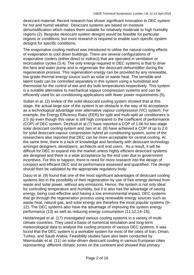
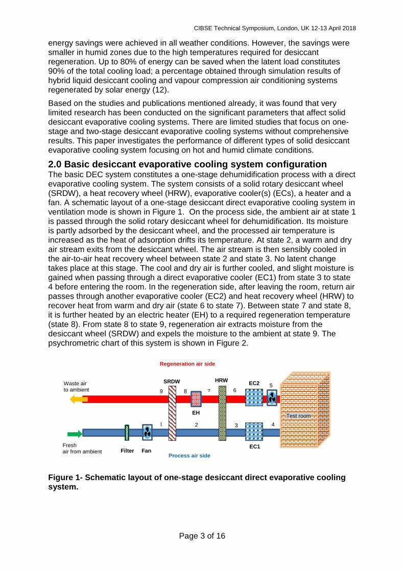
2.0 Basic desiccant evaporative cooling system configuration The basic DEC system constitutes a one-stage dehumidification process with a direct evaporative cooling system. The system consists of a solid rotary desiccant wheel (SRDW), a heat recovery wheel (HRW), evaporative cooler(s) (ECs), a heater and a fan. A schematic layout of a one-stage desiccant direct evaporative cooling system in ventilation mode is shown in Figure 1. On the process side, the ambient air at state 1 is passed through the solid rotary desiccant wheel for dehumidification. Its moisture is partly adsorbed by the desiccant wheel, and the processed air temperature is increased as the heat of adsorption drifts its temperature. At state 2, a warm and dry air stream exits from the desiccant wheel. The air stream is then sensibly cooled in the air-to-air heat recovery wheel between state 2 and state 3. No latent change takes place at this stage. The cool and dry air is further cooled, and slight moisture is gained when passing through a direct evaporative cooler (EC1) from state 3 to state 4 before entering the room. In the regeneration side, after leaving the room, return air passes through another evaporative cooler (EC2) and heat recovery wheel (HRW) to recover heat from warm and dry air (state 6 to state 7). Between state 7 and state 8, it is further heated by an electric heater (EH) to a required regeneration temperature (state 8). From state 8 to state 9, regeneration air extracts moisture from the desiccant wheel (SRDW) and expels the moisture to the ambient at state 9. The psychrometric chart of this system is shown in Figure 2.
Figure 1- Schematic layout of one-stage desiccant direct evaporative cooling system.
Process air side
HRW
4
6 9 8
3 1 2
Regeneration air side
Fresh air from ambient
Waste air to ambient
SRDW EC2
EC1
EH
Test room
Filter Fan
5 7
CIBSE Technical Symposium, London, UK 12-13 April 2018
Page 4 of 16
Figure 2 – Psychrometric chart of the above DEC system.
3.0 Simulation model description As described previously, a desiccant air-conditioning system consists of several components. A brief description of each component is presented in this section with the aim of explaining the selection of specific models for each component of operation in a TRNSYS simulation studio. In the set-up of a DEC system, the input of the one component is linked to the output of the other component.
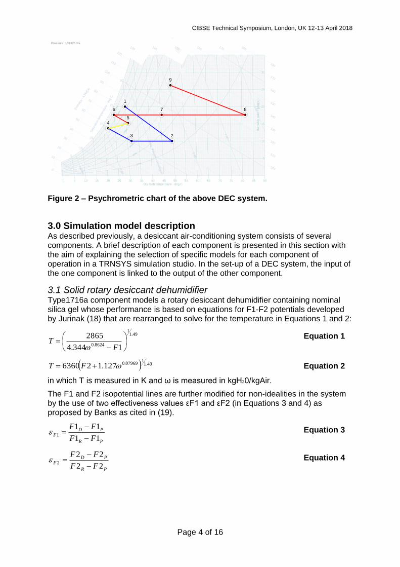
3.1 Solid rotary desiccant dehumidifier Type1716a component models a rotary desiccant dehumidifier containing nominal silica gel whose performance is based on equations for F1-F2 potentials developed by Jurinak (18) that are rearranged to solve for the temperature in Equations 1 and 2:
49.11
8624.0 1344.4
2865
FT
Equation 1
49.11
07969.0127.126360 FT Equation 2
in which T is measured in K and ω is measured in kgH20/kgAir.
The F1 and F2 isopotential lines are further modified for non-idealities in the system by the use of two effectiveness values εF1 and εF2 (in Equations 3 and 4) as proposed by Banks as cited in (19).
PR
FF
FF
11
111
Equation 3
PR
FF
FF
22
222
Equation 4
Ent
halp
y - kJ
/kg(
a)S
atu
ratio
n tem
pera
ture
- d
eg C
Hu
mid
ity r
atio
- g
/kg
(a)
Pressure: 101325 Pa
Dry bulb temperature - deg C0 5 10 15 20 25 30 35 40 45 50 55 60 65 70 75 80 85 90
5
10
15
20
25
30
10%
20%
30%
40%
50%
60%
70%
80%
90%
0.8
0
0.8
5
0.9
0 V
olu
me - cu
.m/kg
(a)
0.9
5
1.0
0
1.0
5
0
10
20
30
40
50
60
70
80
90
100
110
120
130140
150160
170180
100
110
120
130
140
150
160
170
180
5
10
15
20
25
30
1
23
45
6 7 8
9
CIBSE Technical Symposium, London, UK 12-13 April 2018
Page 5 of 16
This model takes the values of εF1 and εF2 as parameters (instead of computing them) and allows controls on a desired process air outlet humidity ratio. The model will determine the temperature of regeneration air required to obtain this ratio.
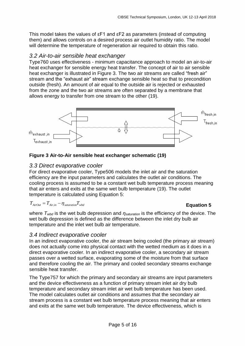
3.2 Air-to-air sensible heat exchanger Type760 uses effectiveness - minimum capacitance approach to model an air-to-air heat exchanger for sensible energy heat transfer. The concept of air to air sensible heat exchanger is illustrated in Figure 3. The two air streams are called “fresh air” stream and the “exhaust air” stream exchange sensible heat so that to precondition outside (fresh). An amount of air equal to the outside air is rejected or exhausted from the zone and the two air streams are often separated by a membrane that allows energy to transfer from one stream to the other (19).
Figure 3 Air-to-Air sensible heat exchanger schematic (19)
3.3 Direct evaporative cooler For direct evaporative cooler, Type506 models the inlet air and the saturation efficiency are the input parameters and calculates the outlet air conditions. The cooling process is assumed to be a constant wet bulb temperature process meaning that air enters and exits at the same wet bulb temperature (19). The outlet temperature is calculated using Equation 5:
wbdsaturationinAirAirOut TTT , Equation 5
where Twbd is the wet bulb depression and ƞsaturation is the efficiency of the device. The wet bulb depression is defined as the difference between the inlet dry bulb air temperature and the inlet wet bulb air temperature.
3.4 Indirect evaporative cooler In an indirect evaporative cooler, the air stream being cooled (the primary air stream) does not actually come into physical contact with the wetted medium as it does in a direct evaporative cooler. In an indirect evaporative cooler, a secondary air stream passes over a wetted surface, evaporating some of the moisture from that surface and therefore cooling the air. The primary and cooled secondary streams exchange sensible heat transfer.
The Type757 for which the primary and secondary air streams are input parameters and the device effectiveness as a function of primary stream inlet air dry bulb temperature and secondary stream inlet air wet bulb temperature has been used. The model calculates outlet air conditions and assumes that the secondary air stream process is a constant wet bulb temperature process meaning that air enters and exits at the same wet bulb temperature. The device effectiveness, which is
CIBSE Technical Symposium, London, UK 12-13 April 2018
Page 6 of 16
defined by Equation 6 below as per ASHRAE Handbook of Applications 1999 as cited in (19).
inprimaryinprimary
outprimaryinprimary
WBT
TT
,,
,,
Equation 6
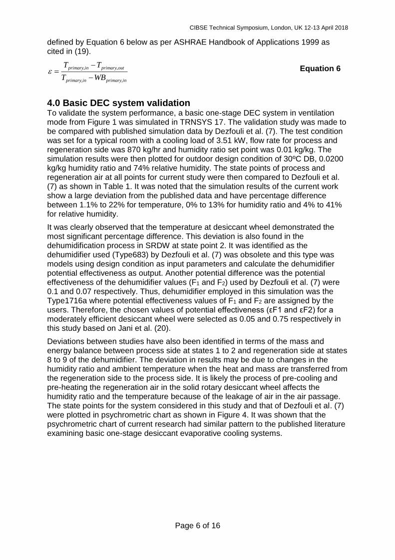
4.0 Basic DEC system validation To validate the system performance, a basic one-stage DEC system in ventilation mode from Figure 1 was simulated in TRNSYS 17. The validation study was made to be compared with published simulation data by Dezfouli et al. (7). The test condition was set for a typical room with a cooling load of 3.51 kW, flow rate for process and regeneration side was 870 kg/hr and humidity ratio set point was 0.01 kg/kg. The simulation results were then plotted for outdoor design condition of 30ºC DB, 0.0200 kg/kg humidity ratio and 74% relative humidity. The state points of process and regeneration air at all points for current study were then compared to Dezfouli et al. (7) as shown in Table 1. It was noted that the simulation results of the current work show a large deviation from the published data and have percentage difference between 1.1% to 22% for temperature, 0% to 13% for humidity ratio and 4% to 41% for relative humidity.
It was clearly observed that the temperature at desiccant wheel demonstrated the most significant percentage difference. This deviation is also found in the dehumidification process in SRDW at state point 2. It was identified as the dehumidifier used (Type683) by Dezfouli et al. (7) was obsolete and this type was models using design condition as input parameters and calculate the dehumidifier potential effectiveness as output. Another potential difference was the potential effectiveness of the dehumidifier values (F1 and F2) used by Dezfouli et al. (7) were 0.1 and 0.07 respectively. Thus, dehumidifier employed in this simulation was the Type1716a where potential effectiveness values of F1 and F2 are assigned by the users. Therefore, the chosen values of potential effectiveness (εF1 and εF2) for a moderately efficient desiccant wheel were selected as 0.05 and 0.75 respectively in this study based on Jani et al. (20).
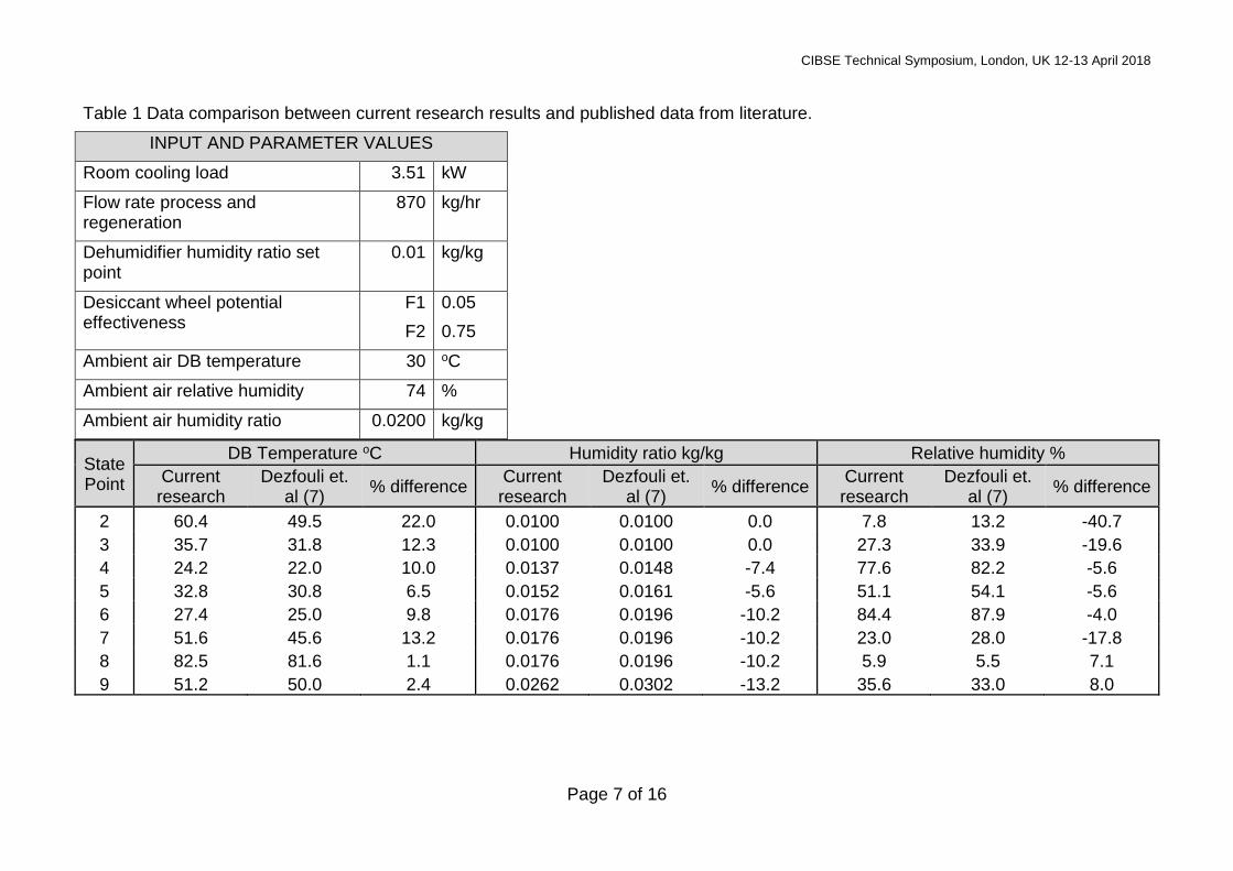
Deviations between studies have also been identified in terms of the mass and energy balance between process side at states 1 to 2 and regeneration side at states 8 to 9 of the dehumidifier. The deviation in results may be due to changes in the humidity ratio and ambient temperature when the heat and mass are transferred from the regeneration side to the process side. It is likely the process of pre-cooling and pre-heating the regeneration air in the solid rotary desiccant wheel affects the humidity ratio and the temperature because of the leakage of air in the air passage. The state points for the system considered in this study and that of Dezfouli et al. (7) were plotted in psychrometric chart as shown in Figure 4. It was shown that the psychrometric chart of current research had similar pattern to the published literature examining basic one-stage desiccant evaporative cooling systems.
CIBSE Technical Symposium, London, UK 12-13 April 2018
Page 7 of 16
Table 1 Data comparison between current research results and published data from literature.
INPUT AND PARAMETER VALUES
Room cooling load 3.51 kW
Flow rate process and regeneration
870 kg/hr
Dehumidifier humidity ratio set point
0.01 kg/kg
Desiccant wheel potential effectiveness
F1
F2
0.05
0.75
Ambient air DB temperature 30 oC
Ambient air relative humidity 74 %
Ambient air humidity ratio 0.0200 kg/kg
State Point
DB Temperature oC Humidity ratio kg/kg Relative humidity %
Current research
Dezfouli et. al (7)
% difference Current research
Dezfouli et. al (7)
% difference Current research
Dezfouli et. al (7)
% difference
2 60.4 49.5 22.0 0.0100 0.0100 0.0 7.8 13.2 -40.7
3 35.7 31.8 12.3 0.0100 0.0100 0.0 27.3 33.9 -19.6
4 24.2 22.0 10.0 0.0137 0.0148 -7.4 77.6 82.2 -5.6
5 32.8 30.8 6.5 0.0152 0.0161 -5.6 51.1 54.1 -5.6
6 27.4 25.0 9.8 0.0176 0.0196 -10.2 84.4 87.9 -4.0
7 51.6 45.6 13.2 0.0176 0.0196 -10.2 23.0 28.0 -17.8
8 82.5 81.6 1.1 0.0176 0.0196 -10.2 5.9 5.5 7.1
9 51.2 50.0 2.4 0.0262 0.0302 -13.2 35.6 33.0 8.0
CIBSE Technical Symposium, London, UK 12-13 April 2018
Page 8 of 16
Figure 4 Psychrometric comparison between the results of the current research with the simulation results of Dezfouli et al. (7).
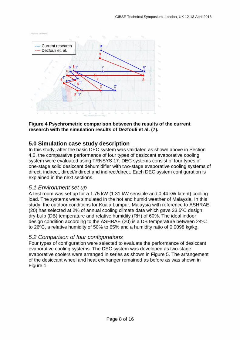
5.0 Simulation case study description In this study, after the basic DEC system was validated as shown above in Section 4.0, the comparative performance of four types of desiccant evaporative cooling system were evaluated using TRNSYS 17. DEC systems consist of four types of one-stage solid desiccant dehumidifier with two-stage evaporative cooling systems of direct, indirect, direct/indirect and indirect/direct. Each DEC system configuration is explained in the next sections.
5.1 Environment set up A test room was set up for a 1.75 kW (1.31 kW sensible and 0.44 kW latent) cooling load. The systems were simulated in the hot and humid weather of Malaysia. In this study, the outdoor conditions for Kuala Lumpur, Malaysia with reference to ASHRAE (20) has selected at 2% of annual cooling climate data which gave 33.5ºC design dry-bulb (DB) temperature and relative humidity (RH) of 60%. The ideal indoor design condition according to the ASHRAE (20) is a DB temperature between 24ºC to 26ºC, a relative humidity of 50% to 65% and a humidity ratio of 0.0098 kg/kg.
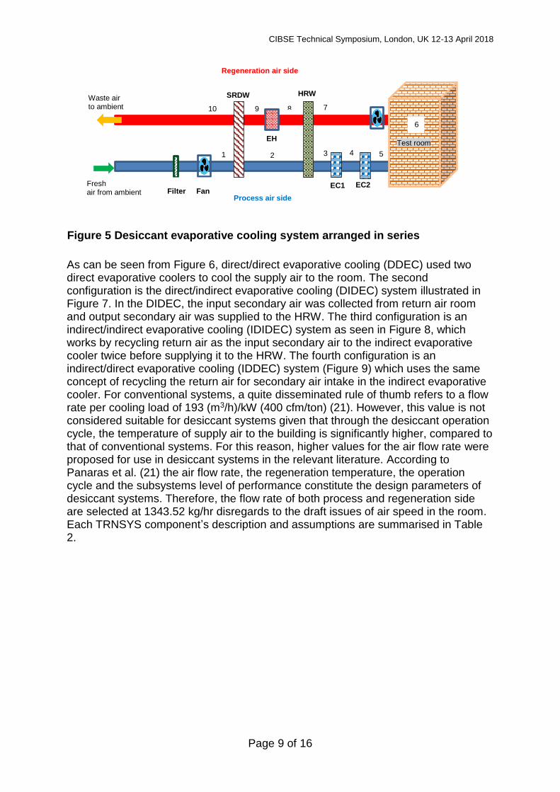
5.2 Comparison of four configurations Four types of configuration were selected to evaluate the performance of desiccant evaporative cooling systems. The DEC system was developed as two-stage evaporative coolers were arranged in series as shown in Figure 5. The arrangement of the desiccant wheel and heat exchanger remained as before as was shown in Figure 1.
Ent
halp
y - kJ
/kg(
a)S
atu
ratio
n tem
pera
ture
- d
eg C
Hu
mid
ity r
atio
- g
/kg
(a)
Pressure: 101325 Pa
Dry bulb temperature - deg C0 5 10 15 20 25 30 35 40 45 50 55 60 65 70 75 80 85 90
5
10
15
20
25
30
10%
20%
30%
40%
50%
60%
70%
80%
90%
0.8
0
0.8
5
0.9
0 V
olu
me - cu
.m/kg
(a)
0.9
5
1.0
0
1.0
5
0
10
20
30
40
50
60
70
80
90
100
110
120
130140
150160
170180
100
110
120
130
140
150
160
170
180
5
10
15
20
25
30
WinterComfort
Zone
SummerComfort
Zone
1
2
3
4
6
9
2'
3'
4'
5'
6' 7' 8'
9'
87
1'
5
---- Current research ---- Dezfouli et. al. (15)
CIBSE Technical Symposium, London, UK 12-13 April 2018
Page 9 of 16
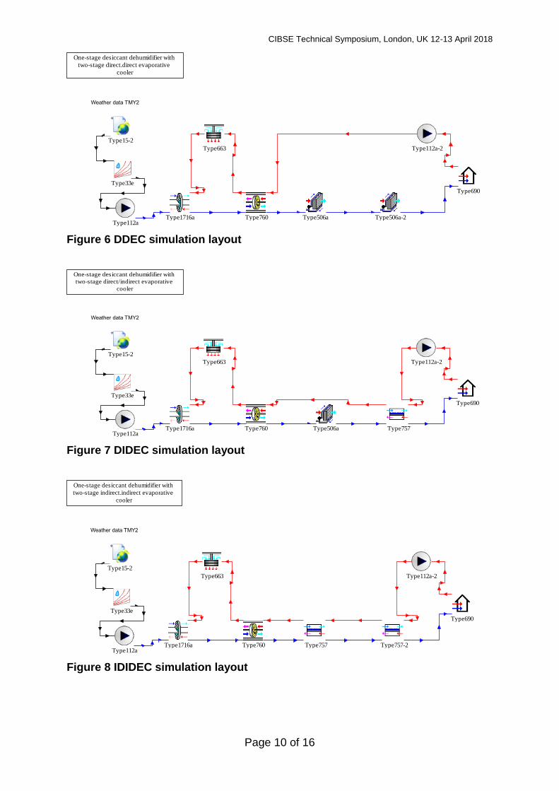
As can be seen from Figure 6, direct/direct evaporative cooling (DDEC) used two direct evaporative coolers to cool the supply air to the room. The second configuration is the direct/indirect evaporative cooling (DIDEC) system illustrated in Figure 7. In the DIDEC, the input secondary air was collected from return air room and output secondary air was supplied to the HRW. The third configuration is an indirect/indirect evaporative cooling (IDIDEC) system as seen in Figure 8, which works by recycling return air as the input secondary air to the indirect evaporative cooler twice before supplying it to the HRW. The fourth configuration is an indirect/direct evaporative cooling (IDDEC) system (Figure 9) which uses the same concept of recycling the return air for secondary air intake in the indirect evaporative cooler. For conventional systems, a quite disseminated rule of thumb refers to a flow rate per cooling load of 193 (m3/h)/kW (400 cfm/ton) (21). However, this value is not considered suitable for desiccant systems given that through the desiccant operation cycle, the temperature of supply air to the building is significantly higher, compared to that of conventional systems. For this reason, higher values for the air flow rate were proposed for use in desiccant systems in the relevant literature. According to Panaras et al. (21) the air flow rate, the regeneration temperature, the operation cycle and the subsystems level of performance constitute the design parameters of desiccant systems. Therefore, the flow rate of both process and regeneration side are selected at 1343.52 kg/hr disregards to the draft issues of air speed in the room. Each TRNSYS component’s description and assumptions are summarised in Table 2.
5
Process air side
HRW
4
7 10 9
3 1 2
Regeneration air side
Fresh air from ambient
Waste air to ambient
SRDW
EC2 EC1
EH
Test room
Filter Fan
6
8
Figure 5 Desiccant evaporative cooling system arranged in series
CIBSE Technical Symposium, London, UK 12-13 April 2018
Page 10 of 16
Figure 6 DDEC simulation layout
Figure 7 DIDEC simulation layout
Figure 8 IDIDEC simulation layout
Type33e
Type1716a Type760
Type690
Type663
Type15-2
Type112a
Weather data TMY2
One-stage desiccant dehumidifier with
two-stage direct.direct evaporative
cooler
Type112a-2
Type506a Type506a-2
Type33e
Type1716a Type760 Type506a
Type690
Type663
Type15-2
Type112aType757
Weather data TMY2
One-stage desiccant dehumidifier with
two-stage direct/indirect evaporative
cooler
Type112a-2
Type33e
Type1716a Type760
Type690
Type663
Type15-2
Type112aType757-2
Weather data TMY2
One-stage desiccant dehumidifier with
two-stage indirect.indirect evaporative
cooler
Type112a-2
Type757
CIBSE Technical Symposium, London, UK 12-13 April 2018
Page 11 of 16
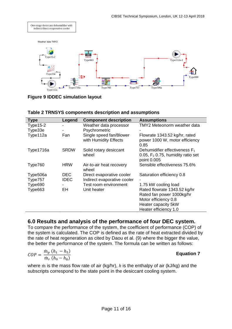
Figure 9 IDDEC simulation layout
Table 2 TRNSYS components description and assumptions
Type Legend Component description Assumptions
Type15-2 - Weather data processor TMY2 Meteonorm weather data Type33e - Psychrometric - Type112a Fan Single speed fan/Blower
with Humidity Effects Flowrate 1343.52 kg/hr, rated power 1000 W, motor efficiency 0.85
Type1716a SRDW Solid rotary desiccant wheel
Dehumidifier effectiveness F1 0.05, F2 0.75, humidity ratio set point 0.005
Type760 HRW Air-to-air heat recovery wheel
Sensible effectiveness 75.6%
Type506a DEC Direct evaporative cooler Saturation efficiency 0.8 Type757 IDEC Indirect evaporative cooler - Type690 - Test room environment 1.75 kW cooling load Type663 EH Unit heater Rated flowrate 1343.52 kg/hr
Rated fan power 1000kg/hr Motor efficiency 0.8 Heater capacity 5kW Heater efficiency 1.0
6.0 Results and analysis of the performance of four DEC system. To compare the performance of the system, the coefficient of performance (COP) of the system is calculated. The COP is defined as the rate of heat extracted divided by the rate of heat regeneration as cited by Daou et al. (9) where the bigger the value, the better the performance of the system. The formula can be written as follows:
𝐶𝑂𝑃 = ṁ𝑝 (ℎ1 − ℎ5)
ṁ𝑟 (ℎ9 − ℎ8) Equation 7
where ṁ is the mass flow rate of air (kg/hr), h is the enthalpy of air (kJ/kg) and the subscripts correspond to the state point in the desiccant cooling system.
Type33e
Type1716a Type760 Type506a
Type690
Type663
Type15-2
Type112aType757
Weather data TMY2
One-stage desiccant dehumidifier with
indirect/direct evaporative cooler
Type112a-2
CIBSE Technical Symposium, London, UK 12-13 April 2018
Page 12 of 16
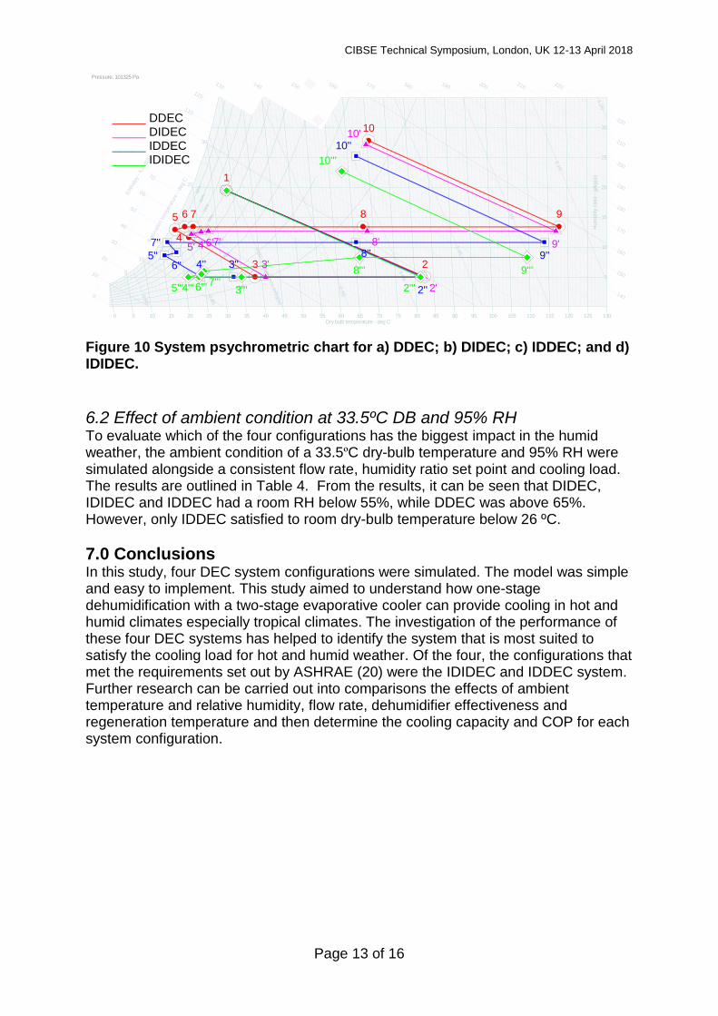
6.1 Effect of ambient condition at 33.5ºC DB and 60% RH From the simulation results for the four configurations as mentioned above, ten selected state points of the systems are plotted on a psychrometric chart and shown in Figures 10. By referring to the psychrometric chart in Figure 10, in the DDEC system, the ambient air at state 1 is passed through the solid rotary desiccant wheel for dehumidification on the process side. Warm and dry air stream exits from the desiccant wheel at state 2. The air stream is then sensibly cooled in the air-to-air heat recovery wheel between state 2 and state 3. The cool and dry air is further cooled, and slight moisture is gained when passing through first direct evaporative cooler (EC1) from state 3 to state 4 and further cooled by second direct evaporative cooler (EC2) from state 4 to state 5 before entering the room. In the regeneration side, after leaving the room (state 6), return air passes through the heat recovery wheel (HRW) to recover heat from warm and dry air (state 7 to state 8). Between state 8 and state 9, it is further heated by an electric heater (EH) to a required regeneration temperature (state 9). From state 9 to state 10, regeneration air extracts moisture from the desiccant wheel (SRDW) and expels the moisture to the ambient at state 10. Other configurations having similar process except between state 3 to 7 where evaporative cooling process occurs.
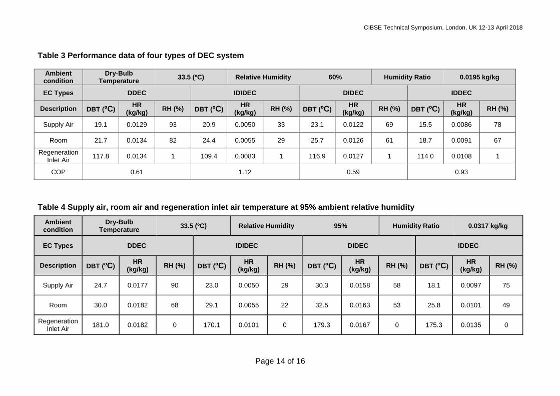
Hence, the comparison of performance data for four configurations were tabulated in Table 3. As referred to in Table 3, the achieved room temperature (at state 6) of all four systems was below 26oC which met the recommended indoor comfort condition (20). However, as recommended by ASHRAE (20), only IDIDEC and IDDEC met the acceptable indoor comfort conditions of both the room DB temperature and humidity ratio of 26ºC below and 0.0098 kg/kg respectively. The IDIDEC had the lowest humidity ratio in the supply and room air condition because of the humidity ratio set point in SRDW was set at 0.005 kg/kg where this too dry. This set point value can be adjusted higher in IDIDEC since no humidity imposed to the system in indirect EC. Therefore, it had the lowest regeneration temperature required compared to the other three configurations. The humidity ratio in the room of DDEC and DIDEC were above the comfort condition of 0.0098 kg/kg as stated in ASHRAE (20). It was observed that direct evaporative cooler will add moisture in the air, while indirect evaporative cooler will not. Therefore, the humidity ratio set point (HRSP) in desiccant wheel can be higher if an indirect evaporative cooler was used. The IDIDEC system has shown the highest COP value at 1.12 while the lowest was 0.59 for DIDEC system. The COP of DDEC system is 0.61 which was higher compared to experimental study of similar configuration carried out by Kodama et al. (23) with a COP of 0.540. The IDDEC system had a COP of 0.93. Based on this comparison of all four configurations, it was found that the IDIDEC and IDDEC systems have met the requirements of ASHRAE at selected input parameters.
CIBSE Technical Symposium, London, UK 12-13 April 2018
Page 13 of 16
Figure 10 System psychrometric chart for a) DDEC; b) DIDEC; c) IDDEC; and d) IDIDEC.
6.2 Effect of ambient condition at 33.5ºC DB and 95% RH To evaluate which of the four configurations has the biggest impact in the humid weather, the ambient condition of a 33.5ºC dry-bulb temperature and 95% RH were simulated alongside a consistent flow rate, humidity ratio set point and cooling load. The results are outlined in Table 4. From the results, it can be seen that DIDEC, IDIDEC and IDDEC had a room RH below 55%, while DDEC was above 65%. However, only IDDEC satisfied to room dry-bulb temperature below 26 ºC.
7.0 Conclusions In this study, four DEC system configurations were simulated. The model was simple and easy to implement. This study aimed to understand how one-stage dehumidification with a two-stage evaporative cooler can provide cooling in hot and humid climates especially tropical climates. The investigation of the performance of these four DEC systems has helped to identify the system that is most suited to satisfy the cooling load for hot and humid weather. Of the four, the configurations that met the requirements set out by ASHRAE (20) were the IDIDEC and IDDEC system. Further research can be carried out into comparisons the effects of ambient temperature and relative humidity, flow rate, dehumidifier effectiveness and regeneration temperature and then determine the cooling capacity and COP for each system configuration.
Enth
alp
y - kJ
/kg(a
)S
atu
ratio
n tem
pera
ture
- d
eg C
Hu
mid
ity r
atio
- g
/kg
(a)
Pressure: 101325 Pa
Dry bulb temperature - deg C0 5 10 15 20 25 30 35 40 45 50 55 60 65 70 75 80 85 90 95 100 105 110 115 120 125 130
5
10
15
20
25
30
10%
20%
30%
40%
50%
60%
70%
80%
90%
0.8
0
0.8
5
0.9
0 V
olu
me - cu
.m/kg
(a)
0.9
5
1.0
0
1.0
5
1.1
0
1.1
5
1.2
0
0
10
20
30
40
50
60
70
80
90
100
110
120
130140
150160
170180
190200
210220
140
150
160
170
180
190
200
210
220
5
10
15
20
25
30
23
5 6 7 8 9
10
1
7'
3''
7''
5''' 6'''4'''7'''
5''6''
4'5'4 6'
3'
3'''
8''' 9'''
9''9'8'
10'''
10''10'
2'2''2'''
8''4''
_____ DDEC _____ DIDEC _____ IDDEC _____ IDIDEC
CIBSE Technical Symposium, London, UK 12-13 April 2018
Page 14 of 16
Table 3 Performance data of four types of DEC system
Table 4 Supply air, room air and regeneration inlet air temperature at 95% ambient relative humidity
Ambient condition
Dry-Bulb Temperature
33.5 (ºC) Relative Humidity 95% Humidity Ratio 0.0317 kg/kg
EC Types DDEC IDIDEC DIDEC IDDEC
Description DBT (ºC) HR
(kg/kg) RH (%) DBT (ºC)
HR (kg/kg)
RH (%) DBT (ºC) HR
(kg/kg) RH (%) DBT (ºC)
HR (kg/kg)
RH (%)
Supply Air 24.7 0.0177 90 23.0 0.0050 29 30.3 0.0158 58 18.1 0.0097 75
Room 30.0 0.0182 68 29.1 0.0055 22 32.5 0.0163 53 25.8 0.0101 49
Regeneration Inlet Air
181.0 0.0182 0 170.1 0.0101 0 179.3 0.0167 0 175.3 0.0135 0
Ambient condition
Dry-Bulb Temperature
33.5 (ºC) Relative Humidity 60% Humidity Ratio 0.0195 kg/kg
EC Types DDEC IDIDEC DIDEC IDDEC
Description DBT (ºC) HR
(kg/kg) RH (%) DBT (ºC)
HR (kg/kg)
RH (%) DBT (ºC) HR
(kg/kg) RH (%) DBT (ºC)
HR (kg/kg)
RH (%)
Supply Air 19.1 0.0129 93 20.9 0.0050 33 23.1 0.0122 69 15.5 0.0086 78
Room 21.7 0.0134 82 24.4 0.0055 29 25.7 0.0126 61 18.7 0.0091 67
Regeneration Inlet Air
117.8 0.0134 1 109.4 0.0083 1 116.9 0.0127 1 114.0 0.0108 1
COP 0.61 1.12 0.59 0.93
CIBSE Technical Symposium, London, UK 12-13 April 2018
Page 15 of 16
References (1) Buker MS, Riffat SB. Recent developments in solar assisted liquid desiccant
evaporative cooling technology—A review. Energy and Buildings. Elsevier B.V.; 2015;96: 95–108.
(2) Sultan M, El-Sharkawy II, Miyazaki T, Saha BB, Koyama S. An overview of solid desiccant dehumidification and air conditioning systems. Renewable and Sustainable Energy Reviews. Elsevier; 2015;46: 16–29.
(3) Ali M, Vukovic V, Sheikh NA, Ali HM. Performance investigation of solid desiccant evaporative cooling system configurations in different climatic zones. Energy Conversion and Management. Elsevier Ltd; 2015;97: 323–339.
(4) Mei L, Dai YJ. A technical review on use of liquid-desiccant dehumidification for air-conditioning application. Renewable and Sustainable Energy Reviews. 2008;12(3): 662–689.
(5) Mujahid Rafique M, Gandhidasan P, Rehman S, Al-Hadhrami LM. A review on desiccant based evaporative cooling systems. Renewable and Sustainable Energy Reviews. 2015;45: 145–159.
(6) CIBSE. CIBSE Guide F - Energy efficiency in buildings. London: CIBSE Publications; 2012.
(7) Dezfouli MMS, Mat S, Pirasteh G, Sahari KSM, Sopian K, Ruslan MH. Simulation analysis of the four configurations of solar desiccant cooling system using evaporative cooling in tropical weather in Malaysia. International Journal of Photoenergy. 2014;2014.
(8) Jani DB, Mishra M, Sahoo PK. Experimental investigation on solid desiccant–vapor compression hybrid air-conditioning system in hot and humid weather. Applied Thermal Engineering. Elsevier Ltd; 2016;104: 556–564.
(9) Daou K, Wang RZ, Xia ZZ. Desiccant cooling air conditioning: A review. Renewable and Sustainable Energy Reviews. 2006;10(2): 55–77.
(10) Halliday SP, Beggs CB, Sleigh P a. The use of solar desiccant cooling in the UK: A feasibility study. Applied Thermal Engineering. 2002;22(12): 1327–1338.
(11) Mavroudaki P, Beggs CB, Sleigh PA, Halliday SP. The potential for solar powered single-stage desiccant cooling in southern Europe. Applied Thermal Engineering. 2002;22(10): 1129–1140. Available from: [Accessed: 25th June 2015]
(12) Yadav YK. Vapour-compression and liquid-desiccant hybrid solar space-conditioning system for energy conservation. Renewable Energy. 1995;6(7): 719–723.
(13) Xiao F, Ge G, Niu X. Control performance of a dedicated outdoor air system adopting liquid desiccant dehumidification. Applied Energy. 2011;88(1): 143–149.
(14) Mousavi ES, Grosskopf KR. Internal Contaminant Source Dilution and Filtration in Dedicated Outdoor Air Systems. Procedia Engineering. Elsevier B.V.; 2015;118: 12–18.
(15) Ge G, Xiao F, Wang S. Optimization of a liquid desiccant based dedicated outdoor air-chilled ceiling system serving multi-zone spaces. Building Simulation. 2012;5(3): 257–266.
(16) Liu W, Lian Z, Radermacher R, Yao Y. Energy consumption analysis on a dedicated outdoor air system with rotary desiccant wheel. Energy. 2007;32(9): 1749–1760.
(17) Heidarinejad G, Heidarinejad M, Delfani S, Esmaeelian J. Feasibility of using various kinds of cooling systems in a multi-climates country. Energy and

CIBSE Technical Symposium, London, UK 12-13 April 2018
Page 16 of 16
Buildings. 2008;40(10): 1946–1953. (18) Jurinak JJ. Open Cycle Solid Desiccant Cooling - Component Models and
System Simulations. University of Wisconsin-Madison; 1982. (19) Thermal Energy System Specialists L. Volume 06 HVAC Library Mathematical
Reference. TESSLibs 17. Wisconsin, USA; 2014. p. 161–165. Available from: www.tess-inc.com
(20) ASHRAE. ASHRAE HANDBOOK Fundamentals.. SI Edition. 1791 Tullie Circle, N.E., Atlanta, GA 30329; 2013. 995 p.
(21) Panaras G, Mathioulakis E, Belessiotis V. Solid desiccant air-conditioning systems - Design parameters. Energy. 2011;36(5): 2399–2406.
Acknowledgements The first author wishes to express her acknowledgments to Public Works Departments (PWD) and Public Services Departments of Malaysia (PSD) for their scholarship support associated with this study.
View publication statsView publication stats