investigating the performance of generator protection
TRANSCRIPT
INVESTIGATING THE PERFORMANCE OF GENERATOR
PROTECTION RELAYS USING A REAL-TIME
SIMULATOR
by
Yu-Ting Huang
Submitted in the fulfilment of the academic requirement for the degree of Master of Science in
Engineering, in the School of Electrical, Electronic and Computer Engineering, University of
KwaZulu-Natal, Durban, South Africa.
November 2013
DECLARATION 1 – PLAGIARISM
I ,Yu-Ting Huang, declare that:
1. The research reported in this thesis, except where otherwise indicated, is my original
research.
2. This thesis has not been submitted for any degree or examination at any other university.
3. This thesis does not contain other persons’ data, pictures, graphs or other information, unless
specifically acknowledged as being sourced from other persons.
4. This thesis does not contain other persons’ writing, unless specifically acknowledged as
being sourced from other researchers. Where other written sources have been quoted, then:
a. Their words have re-written but the general information attributed to them has been
referenced;
b. Where their exact words have been used, then their writing has been placed in italics
and inside quotation marks, and referenced.
5. This thesis does not contain text, graphics or tables copied and pasted from the Internet,
unless specifically acknowledged, and the source being detailed in the thesis and in the
References sections.
Yu-Ting Huang .............................. ..............................
(BScEng) Signature Date
As the candidate’s Supervisor I agree to the submission of this thesis.
Supervisor: Bruce Rigby .............................. ..............................
(BScEng, MScEng, PhD (Natal), MIEEE) Signature Date
DECLARATION 2 – PUBLICATIONS
DETAILS OF CONTRIBUTION TO PUBLICATIONS that form part and/or include research
presented in this thesis (include publications in preparation, submitted, in press and published and
give details of the contributions of each author to the experimental work and writing of each
publication).
Publication 1:
Y-T Huang, B S Rigby, A B Dehkordi: “Using a new faulted synchronous machine model for
hardware-in-loop testing of a generator protection relay”, Southern African Power System
Protection Conference, 2012.
Publication 2:
Y-T Huang, B S Rigby: “Design and Real-Time Simulator Testing of Generator Protection
Schemes for Low- and High-Impedance Grounding Methods”, PAC World Conference, Cape
Town, 2013.

This thesis is dedicated to my family.
i
ABSTRACT
Real-time simulators have been utilized to perform hardware-in-loop testing of protection relays
and power system controllers for some years. However, hardware-in-loop testing of generator
protection relays has until recently been limited by a lack of suitable dynamic models of
synchronous generators in the real-time simulation environment. Historically, the Park
transformation has been chosen as the mathematical approach for dynamic modelling of electrical
machines in simulation programs, since it greatly simplifies the dynamic equations. However,
generator internal winding faults could not be represented faithfully with the aforementioned
modelling approach due to its mathematical limitations. Recently, a new real-time phase-domain,
synchronous machine model has become available that allows representation of internal winding
faults in the stator circuits of a synchronous machine as well as faults in the excitation systems
feeding the field circuits of these machines. The development of this phase-domain synchronous
machine model for real-time simulators opens up the scope for hardware-in-loop testing of
generator protection relays since the performance of various generator protection elements can now
be examined using the advanced features provided by the new machine model.
This thesis presents a thorough, research-based analysis of the new phase-domain synchronous
generator model in order to assess its suitability for testing modern generator protection schemes.
The thesis reviews the theory of operation and settings calculations of the various elements present
in a particular representative modern numerical generator protection relay and describes the
development of a detailed, real-time digital simulation model of a multi-generator system suitable
for studying the performance of the protection functions provided within this relay. As part of the
development of this real-time model, the thesis presents a custom-developed real-time modelling
approach for representing the load-dependent third-harmonic voltages present in the windings of a
large synchronous generator which are needed in order to test certain types of stator-winding
protection schemes.
The thesis presents the results of detailed, closed-loop testing of the representative generator
protection relay hardware and its settings using the developed models on a real-time digital
simulator. The results demonstrate the correctness of the modelling and testing approach and show
that using the phase-domain synchronous machine model, together with the supplementary models
presented in the thesis, it is possible to evaluate the performance of various generator protective
functions that could not otherwise have been analysed using conventional machine models and
testing techniques.

ii
ACKNOWLEDGEMENTS
I would like to express my immense gratitude towards Professor Rigby, for supervising my work
during this thesis and providing valuable guidance time and time again; furthermore the efforts put
into the correction of the thesis and provision of funds are much appreciated.
Some of the modelling approaches used in this thesis came from the ideas of Dr Ali Dehkordi of
RTDS Technologies, Canada. I am grateful to Dr Dehkordi for these ideas, as well as for a number
of example cases he provided for the RTDS simulators that were most helpful when learning the
SEL 300G protection relay.
I would also like to thank the staff at Durban University of Technology, especially F. D’Almaine
and Regina Naidoo for their support and encouraging words during my studies.
Thanks go to my many friends and colleagues, who over the years offered their kindness and
encouragement, especially Chenal Palhad from the Postgraduate Research Laboratory, for his
valuable advice and encouragement.
The University of KwaZulu-Natal, Durban University of Technology and Schweitzer Engineering
Laboratory South Africa are gratefully acknowledged for providing equipment and facilities to
conduct my research in; the work could not have been completed to a high standard without them.
Finally, I wish to thank my family for their patience, love and support during the years of my
studies.
iii
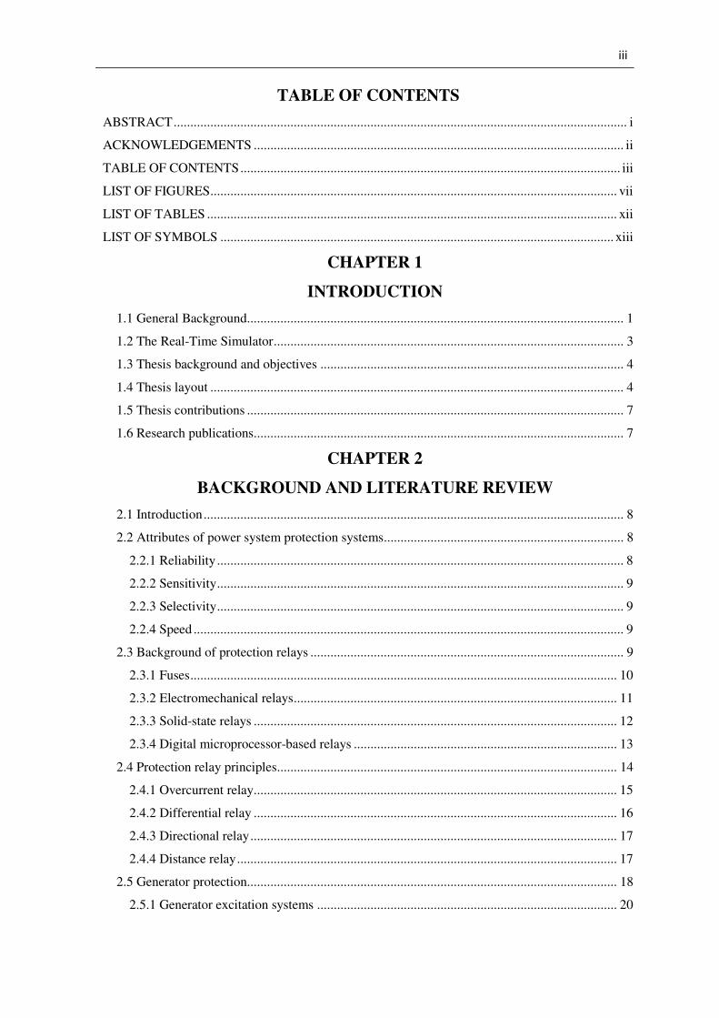
TABLE OF CONTENTS
ABSTRACT ........................................................................................................................................ i
ACKNOWLEDGEMENTS ............................................................................................................... ii
TABLE OF CONTENTS .................................................................................................................. iii
LIST OF FIGURES .......................................................................................................................... vii
LIST OF TABLES ........................................................................................................................... xii
LIST OF SYMBOLS ...................................................................................................................... xiii
CHAPTER 1
INTRODUCTION
1.1 General Background................................................................................................................. 1
1.2 The Real-Time Simulator ......................................................................................................... 3
1.3 Thesis background and objectives ........................................................................................... 4
1.4 Thesis layout ............................................................................................................................ 4
1.5 Thesis contributions ................................................................................................................. 7
1.6 Research publications ............................................................................................................... 7
CHAPTER 2
BACKGROUND AND LITERATURE REVIEW
2.1 Introduction .............................................................................................................................. 8
2.2 Attributes of power system protection systems ........................................................................ 8
2.2.1 Reliability .......................................................................................................................... 8
2.2.2 Sensitivity .......................................................................................................................... 9
2.2.3 Selectivity .......................................................................................................................... 9
2.2.4 Speed ................................................................................................................................. 9
2.3 Background of protection relays .............................................................................................. 9
2.3.1 Fuses ................................................................................................................................ 10
2.3.2 Electromechanical relays ................................................................................................. 11
2.3.3 Solid-state relays ............................................................................................................. 12
2.3.4 Digital microprocessor-based relays ............................................................................... 13
2.4 Protection relay principles ...................................................................................................... 14
2.4.1 Overcurrent relay ............................................................................................................. 15
2.4.2 Differential relay ............................................................................................................. 16
2.4.3 Directional relay .............................................................................................................. 17
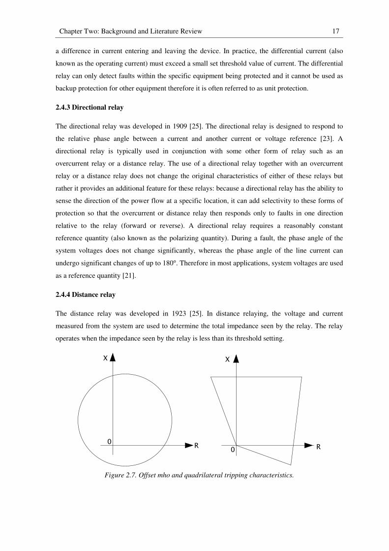
2.4.4 Distance relay .................................................................................................................. 17
2.5 Generator protection............................................................................................................... 18
2.5.1 Generator excitation systems .......................................................................................... 20
iv
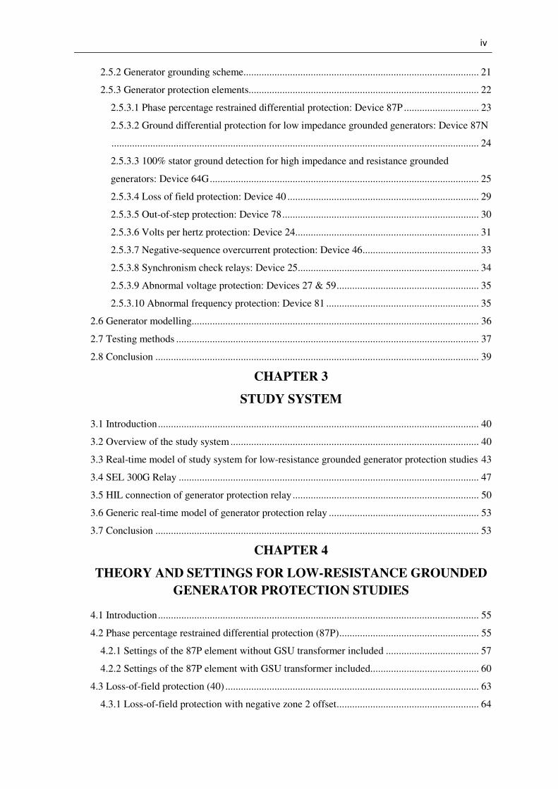
2.5.2 Generator grounding scheme........................................................................................... 21
2.5.3 Generator protection elements......................................................................................... 22
2.5.3.1 Phase percentage restrained differential protection: Device 87P ............................. 23
2.5.3.2 Ground differential protection for low impedance grounded generators: Device 87N
.............................................................................................................................................. 24
2.5.3.3 100% stator ground detection for high impedance and resistance grounded
generators: Device 64G ........................................................................................................ 25
2.5.3.4 Loss of field protection: Device 40 .......................................................................... 29
2.5.3.5 Out-of-step protection: Device 78 ............................................................................ 30
2.5.3.6 Volts per hertz protection: Device 24 ....................................................................... 31
2.5.3.7 Negative-sequence overcurrent protection: Device 46 ............................................. 33
2.5.3.8 Synchronism check relays: Device 25 ...................................................................... 34
2.5.3.9 Abnormal voltage protection: Devices 27 & 59 ....................................................... 35
2.5.3.10 Abnormal frequency protection: Device 81 ........................................................... 35
2.6 Generator modelling............................................................................................................... 36
2.7 Testing methods ..................................................................................................................... 37
2.8 Conclusion ............................................................................................................................. 39
CHAPTER 3
STUDY SYSTEM
3.1 Introduction ............................................................................................................................ 40
3.2 Overview of the study system ................................................................................................ 40
3.3 Real-time model of study system for low-resistance grounded generator protection studies 43
3.4 SEL 300G Relay .................................................................................................................... 47
3.5 HIL connection of generator protection relay ........................................................................ 50
3.6 Generic real-time model of generator protection relay .......................................................... 53
3.7 Conclusion ............................................................................................................................. 53
CHAPTER 4
THEORY AND SETTINGS FOR LOW-RESISTANCE GROUNDED
GENERATOR PROTECTION STUDIES
4.1 Introduction ............................................................................................................................ 55
4.2 Phase percentage restrained differential protection (87P) ...................................................... 55
4.2.1 Settings of the 87P element without GSU transformer included .................................... 57
4.2.2 Settings of the 87P element with GSU transformer included.......................................... 60
4.3 Loss-of-field protection (40) .................................................................................................. 63
4.3.1 Loss-of-field protection with negative zone 2 offset ....................................................... 64
v
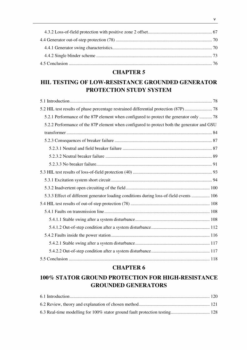
4.3.2 Loss-of-field protection with positive zone 2 offset........................................................ 67
4.4 Generator out-of-step protection (78) .................................................................................... 70
4.4.1 Generator swing characteristics....................................................................................... 70
4.4.2 Single blinder scheme ..................................................................................................... 73
4.5 Conclusion ............................................................................................................................. 76
CHAPTER 5
HIL TESTING OF LOW-RESISTANCE GROUNDED GENERATOR
PROTECTION STUDY SYSTEM
5.1 Introduction ............................................................................................................................ 78
5.2 HIL test results of phase percentage restrained differential protection (87P) ........................ 78
5.2.1 Performance of the 87P element when configured to protect the generator only ........... 78
5.2.2 Performance of the 87P element when configured to protect both the generator and GSU
transformer ............................................................................................................................... 84
5.2.3 Consequences of breaker failure ..................................................................................... 87
5.2.3.1 Neutral and field breaker failure .............................................................................. 87
5.2.3.2 Neutral breaker failure ............................................................................................. 89
5.2.3.3 No breaker failure ..................................................................................................... 91
5.3 HIL test results of loss-of-field protection (40) ..................................................................... 93
5.3.1 Excitation system short circuit ........................................................................................ 94
5.3.2 Inadvertent open circuiting of the field ......................................................................... 100
5.3.3 Effect of different generator loading conditions during loss-of-field events ................ 106
5.4 HIL test results of out-of-step protection (78) ..................................................................... 108
5.4.1 Faults on transmission line ............................................................................................ 108
5.4.1.1 Stable swing after a system disturbance ................................................................. 108
5.4.1.2 Out-of-step condition after a system disturbance ................................................... 112
5.4.2 Faults inside the power station ...................................................................................... 116
5.4.2.1 Stable swing after a system disturbance ................................................................. 117
5.4.2.2 Out-of-step condition after a system disturbance ................................................... 117
5.5 Conclusion ........................................................................................................................... 118
CHAPTER 6
100% STATOR GROUND PROTECTION FOR HIGH-RESISTANCE
GROUNDED GENERATORS
6.1 Introduction .......................................................................................................................... 120
6.2 Review, theory and explanation of chosen method .............................................................. 121
6.3 Real-time modelling for 100% stator ground fault protection testing .................................. 128
vi
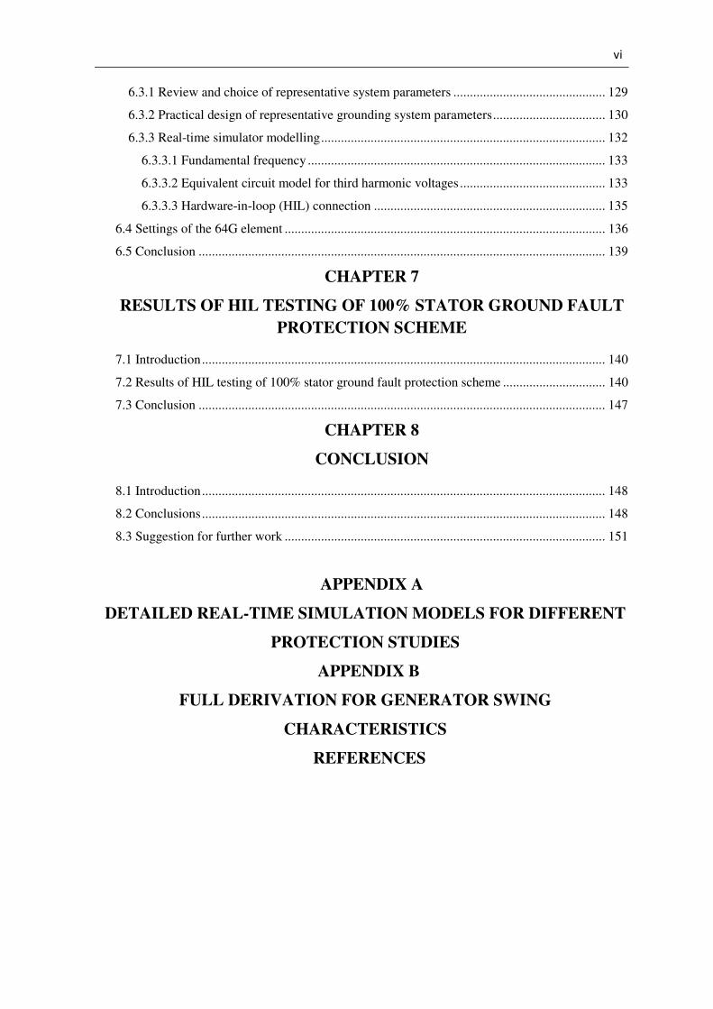
6.3.1 Review and choice of representative system parameters .............................................. 129
6.3.2 Practical design of representative grounding system parameters .................................. 130
6.3.3 Real-time simulator modelling ...................................................................................... 132
6.3.3.1 Fundamental frequency .......................................................................................... 133
6.3.3.2 Equivalent circuit model for third harmonic voltages ............................................ 133
6.3.3.3 Hardware-in-loop (HIL) connection ...................................................................... 135
6.4 Settings of the 64G element ................................................................................................. 136
6.5 Conclusion ........................................................................................................................... 139
CHAPTER 7
RESULTS OF HIL TESTING OF 100% STATOR GROUND FAULT
PROTECTION SCHEME
7.1 Introduction .......................................................................................................................... 140
7.2 Results of HIL testing of 100% stator ground fault protection scheme ............................... 140
7.3 Conclusion ........................................................................................................................... 147
CHAPTER 8
CONCLUSION
8.1 Introduction .......................................................................................................................... 148
8.2 Conclusions .......................................................................................................................... 148
8.3 Suggestion for further work ................................................................................................. 151
APPENDIX A
DETAILED REAL-TIME SIMULATION MODELS FOR DIFFERENT
PROTECTION STUDIES
APPENDIX B
FULL DERIVATION FOR GENERATOR SWING
CHARACTERISTICS
REFERENCES
vii
LIST OF FIGURES
Figure 1.1. Classification of power system stability (reproduced from [11]).
Figure 2.1. Protective device functional elements.
Figure 2.2. Plunger-type relay.
Figure 2.3. Induction disc relay.
Figure 2.4. Moving cup induction relay.
Figure 2.5. Functional block diagram of a digital relay.
Figure 2.6. Definite time and inverse time characteristics of the overcurrent relay.
Figure 2.7. Offset mho and quadrilateral tripping characteristics.
Figure 2.8. Generator capability curve [2].
Figure 2.9. Functional block diagram of a synchronous generator excitation control system
(reproduced from [11]).
Figure 2.10. Differential protection scheme.
Figure 2.11. Ground differential relays (reproduced from [32]).
Figure 2.12. Combined phase percentage differential and ground percentage differential protection
scheme (reproduced from [32]).
Figure 2.13. 100% stator protection: Undervoltage scheme (reproduced from [34]).
Figure 2.14. 100% stator protection: overvoltage scheme (reproduced from [34]).
Figure 2.15. Third-harmonic voltage differential scheme (reproduced from [34]).
Figure 2.16. Neutral injection scheme (reproduced from [32]).
Figure 2.17. Power angle curves at different field currents.
Figure 3.1. Single line diagram of the study system with all four generators represented using a
lumped generator model (4LG).
Figure 3.2. Single line diagram of the study system with three of the units represented using a
lumped generator model (3LG) and one unit represented using a single generator model (1G).
Figure 3.3. Single line diagram of the study system with two of the units represented using a
lumped generator model (2LG) and two units each represented using a single generator model (1G).
Figure 3.4. Phase-domain synchronous machine model.
Figure 3.5. Real-time simulation model of the study system using the representation shown in
Figure 3.2.
Figure 3.6. Real-time modelling details of one generator in the study system for low-resistance
grounding protection tests.
Figure 3.7. AcSELerator QuickSet software setting window.
Figure 3.8a. HMI of the SEL 300G relay: Device overview.
Figure 3.8b. HMI of the SEL 300G relay: Phasors.
Figure 3.8c. HMI of the SEL 300G relay: Instantaneous metering values.

viii
Figure 3.9. Schematic diagram showing real-time closed-loop testing of a SEL 300G generator
protection relay connected to one of the low-resistance grounded generators in the study system.
Figure 3.10. Schematic representation of hardware setup for real-time closed-loop testing.
Figure 3.11. Photograph of the actual test set up.
Figure 4.1. Dual-slope differential characteristic (reproduced from [31]).
Figure 4.2. Logic diagram of phase percentage differential protection (reproduced from [31]).
Figure 4.3. Logic diagram of loss-of-field protection element (reproduced from [31]).
Figure 4.4. Operating characteristic of loss-of-field element with negative zone 2 offset
(reproduced from [31]).
Figure 4.5. Operating characteristic of loss-of-field element with positive zone 2 offset (reproduced
from [31]).
Figure 4.6. Simple power system network and its equivalent circuit diagram.
Figure 4.7.Out-of-step impedance loci on the R-X plane.
Figure 4.8. Operating characteristic of single blinder scheme for out-of-step protection on the R-X
plane.
Figure 4.9. Logic diagram of single blinder scheme for out-of-step protection (reproduced from
[31]).
Figure 5.1. Generator instantaneous voltages during the recorded 15 cycles.
Figure 5.2. Generator instantaneous currents during the recorded 15 cycles.
Figure 5.3. Phase A operating and restraint currents during a phase A internal winding fault.
Figure 5.4. Phase B differential and restraint currents during a phase A internal winding fault.
Figure 5.5. Phase C differential and restraint currents during a phase A internal winding fault.
Figure 5.6. Plot of phase A differential versus restraint current during a phase A fault (Internal
winding fault at 20% of the stator winding from generator neutral).
Figure 5.7. Differential characteristic for Phase A (Internal winding fault at 95% of the winding).
Figure 5.8 Differential characteristic for Phase A (Internal winding fault at 10% of the winding).
Figure 5.9. Phase C differential and restraint currents during a phase A internal winding fault.
Figure 5.10. Binary control signals: neutral and field breaker failure when clearing a stator-ground
fault.
Figure 5.11. Generator winding currents at stator terminal end: neutral and field breaker failure
when clearing a stator-ground fault.
Figure 5.12. Generator winding currents at neutral end: neutral and field breaker failure when
clearing a stator-ground fault.
Figure 5.13. Generator field current: neutral and field breaker failure when clearing a stator-ground
fault.
Figure 5.14. Generator neutral current: neutral and field breaker failure when clearing a stator-
ground fault.

ix
Figure 5.15. Binary control signals: neutral breaker failure when clearing a stator-ground fault.
Figure 5.16. Generator winding currents at stator terminal end: neutral breaker failure when
clearing a stator-ground fault.
Figure 5.17. Generator winding currents at neutral end: neutral breaker failure when clearing a
stator-ground fault.
Figure 5.18. Generator field current: neutral breaker failure when clearing a stator-ground fault.
Figure 5.19. Generator neutral current: neutral breaker failure when clearing a stator-ground fault.
Figure 5.20. Binary control signals: correct clearing of stator-ground fault by all three breakers.
Figure 5.21. Generator winding currents at stator terminal end: correct clearing of stator-ground
fault by all three breakers.
Figure 5.22. Generator winding currents at neutral end: correct clearing of stator-ground fault by all
three breakers.
Figure 5.23. Generator field current: correct clearing of stator-ground fault by all three breakers.
Figure 5.24. Generator neutral current: correct clearing of stator-ground fault by all three breakers.
Figure 5.25. Fault and breaker logic during loss-of-field event (Shorted field circuit).
Figure 5.26. Field current during loss-of-field event (Shorted field circuit).
Figure 5.27. Generator terminal voltage during loss-of-field event (Shorted field circuit).
Figure 5.28. Reactive power output during loss-of-field event (Shorted field circuit).
Figure 5.29. Active power output during loss-of-field event (Shorted field circuit).
Figure 5.30. Generator load angle during loss-of-field event (Shorted field circuit).
Figure 5.31. Generator instantaneous voltages during loss-of-field event (Shorted field circuit).
Figure 5.32. Generator instantaneous currents during loss-of-field event (Shorted field circuit).
Figure 5.33. Positive sequence resistance and reactance during loss-of-field event (Shorted field
circuit).
Figure 5.34. Impedance locus during loss-of-field event (Shorted field circuit).
Figure 5.35. Fault and breaker logic during loss-of-field event (Shorted field circuit).
Figure 5.36. Impedance locus during loss-of-field event (Shorted field circuit).
Figure 5.37. Fault and breaker logic during loss-of-field event (Shorted field circuit).
Figure 5.38. Impedance locus during loss-of-field event (Shorted field circuit).
Figure 5.39. Fault and breaker logic during loss-of-field event (opened field circuit).
Figure 5.40. Field current during loss-of-field event (opened field circuit).
Figure 5.41. Generator terminal voltage during loss-of-field event (opened field circuit).
Figure 5.42. Reactive power output during loss-of-field event (opened field circuit).
Figure 5.43. Active power output during loss-of-field event (opened field circuit).
Figure 5.44. Generator load angle during loss-of-field event (opened field circuit).
Figure 5.45. Generator instantaneous voltages during loss-of-field event (opened field circuit).
Figure 5.46. Generator instantaneous currents during loss-of-field event (opened field circuit).

x
Figure 5.47. Positive sequence resistance and reactance during loss-of-field event (opened field
circuit).
Figure 5.48. Impedance locus during loss-of-field event (opened field circuit).
Figure 5.49. Fault and breaker logic during loss-of-field event (opened field circuit).
Figure 5.50. Impedance locus during loss-of-field event (opened field circuit).
Figure 5.51. Fault and breaker logic during loss-of-field event (opened field circuit).
Figure 5.52. Impedance locus during loss-of-field event (opened field circuit).
Figure 5.53. Impedance loci for different loading conditions during loss-of-field event (shorted
field circuit).
Figure 5.54. Impedance loci for different loading conditions during loss-of-field event (opened
field circuit).
Figure 5.55. Fault and breaker logic during stable power swing condition.
Figure 5.56. Generator instantaneous voltages during stable power swing condition.
Figure 5.57. Generator instantaneous currents during stable power swing condition.
Figure 5.58. Active power output during stable power swing condition.
Figure 5.59. Reactive power output during stable power swing condition.
Figure 5.60. Generator terminal voltage during stable power swing condition.
Figure 5.61. Generator load angle during stable power swing condition.
Figure 5.62. Positive sequence resistance and reactance during stable power swing condition.
Figure 5.63. Impedance locus during stable power swing condition.
Figure 5.64. Fault logic during out-of-step condition.
Figure 5.65. Generator instantaneous voltages during out-of-step condition.
Figure 5.66. Generator instantaneous currents during out-of-step condition.
Figure 5.67. Active power output during out-of-step condition.
Figure 5.68. Reactive power output during out-of-step condition.
Figure 5.69. Generator terminal voltage during out-of-step condition.
Figure 5.70. Generator load angle during out-of-step condition.
Figure 5.71. Positive sequence resistance and reactance during out-of-step condition (78 tripping
blocked).
Figure 5.72. Impedance locus during out-of-step condition (78 tripping blocked).
Figure 5.73. Fault and breaker logic during out-of-step condition (78 tripping enabled).
Figure 5.74. Impedance locus during out-of-step condition (78 tripping enabled).
Figure 5.75. Impedance locus during stable power swing condition.
Figure 5.76. Impedance locus during out-of-step condition.
Figure 6.1. Simplified generator model.
Figure 6.2. Third-harmonic voltage distribution under healthy generator operation.

xi
Figure 6.3. Third-harmonic voltage re-distribution during a stator-ground fault at the generator
terminals.
Figure 6.4. Third-harmonic voltage re-distribution during a stator-ground fault at the generator
neutral.
Figure 6.5. Schematic representation of the distributed capacitances-to-ground in a generator and
its auxiliary equipment.
Figure 6.6. Real-time modelling details used to represent the particular generator under study.
Figure 6.7. Modelling elements for representing the load-dependent characteristics of the
generator’s third-harmonic winding voltages in the equivalent circuit model.
Figure 6.8. Equivalent circuit model for induced third harmonic voltages.
Figure 6.9. Logic diagram of 100% stator ground fault protection (reproduced from [31]).
Figure 7.1. Binary logic variables for the case of a fault at the generator neutral.
Figure 7.2. Generator stator voltages for the case of a fault at the generator neutral.
Figure 7.3. Generator neutral voltage for the case of a fault at the generator neutral.
Figure 7.4. Generator stator currents for the case of a fault at the generator neutral.
Figure 7.5. Variables recorded by the hardware relay’s event recorder for the case of a fault at the
generator neutral.
Figure 7.6. Binary logic variables for the case of a fault at 53% along the stator winding.
Figure 7.7. Generator stator voltages for the case of a fault at 53% along the stator winding.
Figure 7.8. Generator neutral voltage for the case of a fault at 53% along the stator winding.
Figure 7.9. Generator stator currents for the case of a fault at 53% along the stator winding.
Figure 7.10. Variables recorded by the hardware relay’s event recorder for the case of a fault at
53% along the stator winding.
Figure 8.1. Schematic diagram showing proposed real-time, closed-loop testing of a neutral
injection scheme (64S).
Figure 8.2. Schematic diagram showing real-time closed-loop testing of an automatic voltage
regulator.
xii
LIST OF TABLES
Table 2.1: Generator protection elements [31] ................................................................................. 22
Table 4.1. Settings for the 87P element without GSU transformer included ................................... 60
Table 4.2. Settings for the 87P element with GSU transformer included ........................................ 62
Table 4.3. Settings of loss-of-field protection scheme (Negative offset zone 2) ............................. 66
Table 4.4. Settings for loss-of-field protection (Positive offset zone 2) .......................................... 70
Table 4.5. Settings for out-of-step protection (Single blinder scheme) ........................................... 76
Table 5.1. Relay response to internal winding faults on the generator stator .................................. 83
Table 5.2. Relay response to faults applied at location F3 on the study system .............................. 83
Table 5.3. Relay response to faults applied at location F1 on the study system .............................. 84
Table 5.4. Relay response to internal winding faults on the generator stator .................................. 85
Table 5.5. Relay response to turn-to-ground faults on the transformer primary side winding ........ 86
Table 5.6. Relay response to turn-to-turn faults on the transformer primary side winding ............. 86
Table 5.7. Relay response to turn-to-ground faults on the transformer secondary side winding ..... 86
Table 5.8. Relay response to turn-to-turn faults on the transformer secondary side winding .......... 86
Table 5.9. Relay response to faults applied at location F1 on the study system .............................. 87
Table 5.10. Operating conditions of the particular generator under study ..................................... 107
Table 6.1. List of equipment in the diagram of Figure 6.5 with their capacitances-to-ground [45]
........................................................................................................................................................ 130
Table 6.2. Permissible short-time overload factors for grounding transformers [29] .................... 132
Table 6.3. Settings for the 64G element ......................................................................................... 138
Table 7.1. Response of SEL 300G relay’s 100% stator ground protection elements at no load .... 141
Table 7.2. Response of SEL 300G relay’s 100% stator ground protection elements at full load .. 142
xiii
LIST OF SYMBOLS
Acronyms
RTDS Real-Time Digital Simulator
DSP Digital Signal Processor
GUI Graphical User Interface
DAC Digital to Analogue Converter
WIF Workstation Interface
IRC Inter-Rack Communication
A/D Analogue to Digital Converter
IED Intelligent Electronic Devices
RAM Random Access Memory
CPU Central Processing Unit
TCC Time-Current Characteristic
MWFA Modified Winding Function Approach
AVR Automatic Voltage Regulator
PSS Power System Stabilizer
DFT Discrete Fourier Transform
CHAPTER 1
INTRODUCTION
1.1 General Background
New generation and transmission facilities are being constructed due to the increasing power
demand from both society and industry. Since electricity is one of the basic necessities nowadays,
fast growing population leads to higher demand for power. Rapid economic development prompts
industrial activities and hence also increases the power demand. Since both society and industry
rely heavily on electricity, unexpected power outages are not desirable. From past experiences,
numerous large-scale black-outs have been caused by incorrect setting of protection relays and bad
coordination between different protection elements [1],[2]. In order to minimize the disruption to
the system and loss of supply to customers as a result of these problems in future, better modelling
and testing tools are required for engineers to design more secure protection systems. Power system
protection is important in all aspects of the power system such as generation, transmission and
distribution. The objective of the protection relay is to isolate the faulted section of the power
system in a fast manner. The time taken for the protection relay to remove the fault is known as
fault clearing time. The fault clearing time can have a significant influence on the system’s stability.
In the case of some generator and transmission system faults, if the fault is not cleared sufficiently
quickly (within the critical clearing time), one or more generators may lose synchronism and
eventually be tripped out by their generator protection relays. Loss of generation capacity during or
after a fault puts more stress on other generators still connected to the system, and on the system as
a whole; therefore it can also have adverse knock-on effects on system stability such as voltage
collapse due to insufficient reactive power support [3].
It is a great challenge for protection engineers to design a protection system with high security
since the complexity of interconnected power systems has increased due to the increasing demand
for power. In order to understand the behaviour of complex power systems under steady-state or
transient conditions, different power system simulators have typically been used such as PSCAD,
EMTP/ATP, PSS/E and DIgSILENT [4],[5]. These power system simulators are used to simulate
different system scenarios and contingencies, and the results can be used for protection relay
settings or design of power system controllers.
The development of real-time digital simulation opened up a whole new approach for protection
relay testing and power system controller testing. Before the advent of real-time simulation,
protection relays and power system controllers were often tested using open-loop injection of test
currents and voltages into the physical equipment. Open-loop testing has a significant disadvantage

Chapter One: Introduction 2
since the protection relays can only be tested under pre-simulated test scenarios and their
interaction with the power system cannot be predicted. Due to this limitation, the performance of
some protection elements could not be verified via open-loop tests. However, these limitations of
open-loop relay and controller testing were greatly reduced after real-time simulators became
available. Over the years, use of real-time simulators became more and more widespread because
they possess certain capabilities which conventional power system simulation lacks [5],[6]. Real-
time simulators provide the capability to conduct detailed closed-loop testing of physical protection
hardware that allows live interaction between the power system simulation model and the physical
equipment under test.
It has been possible to conduct highly-detailed closed-loop testing of most types of protection
relays and system controllers using real-time simulators for some years [7],[8],[9]. However,
generator protection is one area where the full potential of real-time simulator testing could not
initially be realised because the mathematical models used to represent the electrical machines in
simulation studies have had some limitations. The dynamic equations of electrical machines are
typically recast into a two-axis (dq) coordinate frame using the Park transform for more convenient
solution in power system simulation programs. This two-axis mathematical model of the generator
is highly detailed and well-suited for use in power system stability studies in which the dynamic
response of the generators to external disturbances is of interest. However, it is not suitable for
testing most generator protection relay functions because of the two-axis structure of the model’s
dynamic equations, with which it has not historically been possible to represent internal winding
faults accurately. However, the recent development of phase-domain real-time synchronous
machine models has opened up new scope for generator protection relay testing [10].
The settings of generator controllers and protection systems and the margin between generator
operating points and their capability limits all have important influences on the stability of the
system as a whole. If the generators have tight operating margins, the stress of the power system
increases and therefore the system is more susceptible to disturbances. The coordination between
different generator controllers and generator protection elements is also important. Poorly
coordinated protection systems can trip the generator during the post-fault period [1],[2].
Misoperation of the protection systems on any item of electrical equipment, but especially of those
protecting a generator, will pose a large disturbance to the system and threaten the stability of the
power system. The study of generator protection systems and their performance is closely linked to
the area of power system stability because generators play such a big role in the stability of the
power system as a whole. Furthermore, the operation of a generator’s protection schemes will
influence the power system’s stability, and power system stability issues will in turn affect the
performance of individual generator protection schemes. Hence, the study of generator protection

Chapter One: Introduction 3
requires some understanding of both generator and system stability. The diagram shown in Figure
1.1 illustrates how different stability issues in the power system are classified within the broad
subject area of power system stability.
Figure 1.1. Classification of power system stability (reproduced from [11]).
1.2 The Real-Time Simulator
The work presented in this thesis was carried out on a RTDS Technologies real-time digital
simulator (RTDSTM
). Although the RTDS is a type of power system simulator, its philosophy is
somewhat different from conventional power system simulators. The principal purpose of the real-
time simulator is not just to execute the simulation in real time but also to allow physical
equipment under study to be connected to it, thereby allowing advanced testing of protection relays
and system controllers to be carried out relatively easily.
The technology used to implement protection functions has developed from electromechanical
relays to sophisticated microprocessor-based relays. Modern protection relays are highly complex
systems and it is very difficult to represent the detailed characteristics of an individual
manufacturer’s relays in a power system simulation by means of mathematical models [12]. This is
one of the reasons why the real-time simulator is a favourable option for protection engineers since
it can be used for hardware-in-loop testing of actual protection relays and system controllers. The
equipment that is connected to the real-time simulator for testing can interact with the power
Power System Stability
Angle Stability
Long-term Stability
Control Modes
Transient Stability
Mid-term Stability
Torsional Modes
Voltage Stability
Large-Disturbance Voltage Stability
Small-Disturbance Voltage Stability
Interarea Modes
Non-oscillatory Instability
Small-Signal Stability
Oscillatory Instability
Local Plant Modes

Chapter One: Introduction 4
system simulation in real time. The hardware-in-loop testing can be used for the verification of the
equipment performance under different system scenarios and contingencies.
RSCAD is the software for the real-time simulator which comprises a group of sub-programs
(DRAFT, RUNTIME, TLINE, CABLE and MULTIPLOT) that are used to program, run and
control the real-time simulator. Both DRAFT and RUNTIME are Graphical User Interface (GUI)
based sub-programs. Detailed models of the power system can be developed in DRAFT while the
development of the visual interface for monitoring and interaction purposes is done in RUNTIME
[13]. Over the years, the environment of RSCAD has been improved due to collaboration between
the manufacturer of the simulator and some well-known companies in the field of electrical
engineering [14],[15],[16]. The real-time simulator is usually used for hardware-in-loop testing of
physical equipment. However, it is not always necessary to connect a specific manufacturer’s
physical equipment to the real-time simulator if the user wants to perform closed-loop analysis of a
category of protection or control equipment and its interaction with the power system under study.
The control system modelling software in RSCAD offers various control system component
models which can be used for the development of real-time simulation models of the test
equipment [12]. The software also provides different pre-developed generic models of protection
relays for real-time simulation studies [17]. These generic relay models are highly-detailed and
possess all the principal functional elements typically found in actual protection relay hardware. In
the protection studies carried out in this thesis, the generic dynamic model of a generator protection
relay provided within RSCAD was used in parallel with an actual manufacturer’s protection relay
hardware (SEL 300G) in order to gain further insight into the hardware relay’s behaviour during
the tests.
1.3 Thesis background and objectives
The performance of many protection relays can, and has been, successfully evaluated by
conducting hardware-in-loop testing using a real-time simulator. However, the performance of
some generator protection elements could not previously be evaluated in this way due to certain
limitations of the mathematical approach normally used for dynamic modelling of synchronous
machines in simulation programs. The well-known two-axis synchronous machine model had a
limited ability to represent internal winding faults in the stator circuits of the machine and therefore
none of the generator stator winding protection schemes could be evaluated using such models.
A recently-developed phase-domain synchronous machine model has the ability to represent
internal winding faults on the stator circuit of a generator. This new machine model also allows
detailed electrical circuit representation of the generator’s excitation input. The research in this
thesis has been motivated by the development of this machine model, since its capabilities now

Chapter One: Introduction 5
enable important additional elements of generator protection relays to be tested which technically
could not be achieved in the past.
Although some proof-of-principle studies have been carried out by using the generic RSCAD
generator protection relay model in order to demonstrate the capabilities of the new phase-domain
synchronous machine model [18], there is very little experience on the real-time closed-loop testing
of any actual generator protection relay hardware using this new machine model. The aim of this
thesis was to carry out a thorough, research-based analysis of the new synchronous generator
model and its application in generator protection and control studies using an actual manufacturer’s
protection relay hardware (SEL 300G), with the objective being to gain a better understanding of
the strengths and limitations of the newly developed phase-domain synchronous machine model.
At the same time, the performance of particular protection elements provided by the generator
protection relay, and the most appropriate way to set them, can be better understood through such a
study as a result of the ability to test these elements in a realistic manner using the new generator
model.
1.4 Thesis layout
This thesis has eight main chapters. Chapter One provides the introduction and background to the
thesis and the motivation behind the work.
Chapter Two provides an overview of general power system protection concepts together with
different protection philosophies and technologies. A general review of all the different types of
protection element commonly used in generator protection is also presented in this chapter. Finally,
the chapter provides some background to the generator modelling and testing approaches that are
followed in the thesis.
Chapter Three reviews the main functional elements and theory of operation of both the RSCAD
generic real-time model of a generator protection relay and the actual hardware protection relay
(SEL 300G), both of which are used in the studies of the thesis. The chapter then presents the
details of the chosen study system and development of the real-time model of this system used in
later chapters. The details of the interfacing of this real-time model to the testing equipment are
also included in order to demonstrate how hardware-in-loop testing is carried out for this particular
research project.
Chapter Four focuses in more detail on the theory of operation and setting calculations of the
particular generator protection elements that are actually used in the research study, namely phase
Chapter One: Introduction 6
percentage restrained differential protection (87P), loss-of-field protection (40) and out-of-step
protection (78). Different setting considerations for each element are also discussed within this
chapter.
Chapter Five contains different hardware-in-loop testing results under various fault scenarios for
each of the generator protection elements described in Chapter Four. The results of these tests are
used to assess the performance and limitations of each of the studied protection elements.
In the detailed theory and studies presented in Chapter Four and Five of the thesis, the generator is
assumed to be grounded using a low-resistance grounding scheme for which differential protection
of the stator winding is appropriate. The alternative method of grounding a generator is by means
of some form of high-resistance grounding technique which then requires the use of very different
types of protection against ground faults in the stator windings. Two distinct protection schemes
are commonly used for generator stator winding protection when the generator is grounded through
high resistance: either a neutral injection scheme (64S) or a 100% stator ground fault protection
scheme (64G) can be used to provide full protection coverage for the generator winding. However,
a 100% stator ground fault protection scheme is the focus in this thesis since this is the protection
scheme provided by the particular hardware relay (SEL 300G) that was available for this work.
Chapter Six describes the recommended practice and procedures followed in the thesis to design a
high-resistance grounding scheme for the generators in the study system and the modelling of this
system in the real-time simulation environment so that the subsequent testing of the SEL 300G’s
100% stator ground fault protection scheme would be carried out on a system with representative
parameters and practical characteristics.
Chapter Seven contains the results of detailed hardware-in-loop testing of the relay’s 100% stator
ground fault protection scheme using the detailed real-time model of the generator and its
grounding scheme described in Chapter Six. The results are used to assess the suitability of using
real-time simulation models of synchronous generators for hardware-in-loop testing of 100% stator
ground fault schemes by comparing the measured performance (stator winding coverage) of the
sub-elements making up the scheme against the performance of these elements expected from
theory.
Chapter Eight presents the conclusions of the thesis research as well as recommendations for
further studies.
Chapter One: Introduction 7
1.5 Thesis contributions
Detailed real-time models have been developed to carry out hardware-in-loop studies for particular
generator protection elements. The generators were represented using phase-domain synchronous
machine models in the simulation studies. Through this research project, the validity of testing an
industrial generator protection relay using the phase-domain synchronous machine model has been
established.
Although the phase-domain synchronous machine model provided to general users of RSCAD
allows realistic representation of internal winding faults on a generator, it does not represent phase-
belt harmonics in the generator stator winding. Consequently, this machine model is not able, on its
own, to represent the third-harmonic voltages in the stator windings that are relied upon by some
forms of 100% stator ground fault protection schemes to detect stator winding faults. In this thesis,
extra modelling effort was therefore put into developing a custom real-time model to simulate the
generated third-harmonic voltages in the stator windings in order to supplement the RSCAD
faulted generator model with the characteristics that it lacks for the purposes of 100% stator ground
fault protection relay testing.
The performances of the phase percentage restrained differential protection (87P), loss-of-field
protection (40), out-of-step protection (78) and 100% stator ground fault protection schemes (64G)
of the SEL 300G generator protection relay have been evaluated by conducting hardware-in-loop
testing of the device. Hardware-in-loop studies can be carried out to test other, different generator
protection relays following a similar approach in the future.
1.6 Research publications
Some of the research findings of this thesis have been presented at local conferences [19],[20].
CHAPTER 2
BACKGROUND AND LITERATURE REVIEW
2.1 Introduction
The broad objectives of this thesis have been presented in the previous chapter, specifically the use
of real-time digital simulators for studying generator protection relay performance. However,
before considering the specific issues associated with generator protection, one must have some
background knowledge on the broader subject of power system protection generally.
Power system protection is a critical branch in the field of electrical engineering. A properly
designed protection system must be able to clear faults as reliably as possible when there is a fault
on the protected equipment, and to remain inactive if the protected equipment is in a healthy
operating state, or if the fault is outside of the protection system’s zone of responsibility.
The fundamentals of power system protection are presented in this chapter in order to explain
different functions and importance of a protection system. Different protection philosophies and
relay technologies are also presented to provide background knowledge on the subject. Since
generator protection is the main focus of the thesis, an overview of the protection elements
provided by modern industrial generator protection relays is also presented. Finally, the chapter
discusses the generator modelling and testing approaches which are followed in this thesis.
2.2 Attributes of power system protection systems
The purpose of a protection system is to detect and remove the faulted section of the power system
network as quickly as possible. The type and location of a fault determines the magnitude of the
disturbance it causes to the power system. The speed of response of a protection relay to a fault
also determines the severity of the disturbance imposed on the system as a result of the fault.
Therefore fast and reliable protection systems are required for fault isolation in order to maintain
the integrity and stability of the power system and to minimize the damage to the faulted plant
itself. This section provides definitions of some terms which are typically used in the field of power
system protection.
2.2.1 Reliability
The reliability of a protection system indicates the correctness of its operation. Dependability and
security are two aspects of the reliability. Complete dependability can be understood as the relay
always operating for faults on the plant it is supposed to protect, while complete security can be
understood as the relay never operating for faults that are not on the plant it is supposed to protect.

Chapter Two: Background and Literature Review 9
Reliability of the relays in a protection scheme is extremely important from the perspective of
power system protection [21],[22],[23].
2.2.2 Sensitivity
A protection system must have the ability to discriminate between a healthy system condition and a
faulty system condition. During an abnormal system condition, measured system quantities will
exceed pre-determined threshold values in order to initiate corrective action to be taken by the
protection system [23]. The margin between trip and restraint regions determines the sensitivity of
the protection system. A protection system with a smaller margin between its trip and restraint
regions will have a higher sensitivity and vice versa [22].
2.2.3 Selectivity
Different protection relays are installed and configured to protect different parts of the power
system. The purpose of protection coordination is to determine graded settings for different
protective relays in order to achieve selectivity in the way that they respond to faults [23]. If the
relay settings are coordinated properly, the primary relay will operate as quickly as possible when
there is a fault within its protection zone and it also provides backup protection with a delay time
for faults outside its protection zone [21]. The backup relay is used in order to try to ensure that the
fault will be isolated if the primary relay fails to operate correctly. Therefore selectivity is also
known as relay coordination which defines the zones of operation of different relays.
2.2.4 Speed
A protection system is required to remove a fault after it has been detected. The time taken by the
protection system to implement this corrective action determines the severity of the equipment
damage and can also influence the stability of the power system. The magnitude of the disturbance
to the power system and the damage to its equipment can be reduced if the fault is isolated in a
short period of time [22].
2.3 Background of protection relays
The principle purpose of protection relays is to discriminate between normal and faulted system
operating conditions. The faulted section of the power system is then isolated from the rest of the
healthy power system. The fault clearing speed can have a significant impact on the system
stability and the severity of the equipment damage. The faster the fault clearing time, the less
damage there will be to the equipment, and the more likely the system will be able to remain in a
stable condition. The time taken to remove a fault is known as the clearing time which is defined
Chapter Two: Background and Literature Review 10
by the summation of the comparison time, decision time and the action time of the protection
systems involved [23].
�� = �� + �� + �� (2.1)
Where �� = clearing time [s] �� = comparison time [s] �� = decision time [s] �� = action time, including circuit breaker operating time [s]
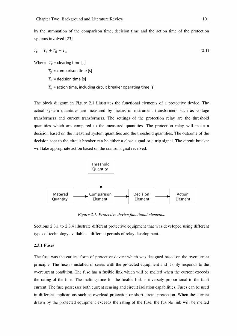
The block diagram in Figure 2.1 illustrates the functional elements of a protective device. The
actual system quantities are measured by means of instrument transformers such as voltage
transformers and current transformers. The settings of the protection relay are the threshold
quantities which are compared to the measured quantities. The protection relay will make a
decision based on the measured system quantities and the threshold quantities. The outcome of the
decision sent to the circuit breaker can be either a close signal or a trip signal. The circuit breaker
will take appropriate action based on the control signal received.
Figure 2.1. Protective device functional elements.
Sections 2.3.1 to 2.3.4 illustrate different protective equipment that was developed using different
types of technology available at different periods of relay development.
2.3.1 Fuses
The fuse was the earliest form of protective device which was designed based on the overcurrent
principle. The fuse is installed in series with the protected equipment and it only responds to the
overcurrent condition. The fuse has a fusible link which will be melted when the current exceeds
the rating of the fuse. The melting time for the fusible link is inversely proportional to the fault
current. The fuse possesses both current sensing and circuit isolation capabilities. Fuses can be used
in different applications such as overload protection or short-circuit protection. When the current
drawn by the protected equipment exceeds the rating of the fuse, the fusible link will be melted
MeteredQuantity
Comparison Element
Decision Element
Action Element
Threshold Quantity

Chapter Two: Background and Literature Review 11
which leads to an open circuit and hence isolates the protected equipment. Fuses are still widely
used due to their simplicity and low cost. Usually each fuse has a chart for coordination purposes.
2.3.2 Electromechanical relays
There are two types of electromechanical relays: the plunger-type and induction-type relays. The
structure of the plunger-type electromechanical relays is a moving solenoid plunger placed inside a
stationary electromagnet as illustrated in Figure 2.2. The mass of the plunger determines the
operating time of the relay; therefore it can be adjusted to suit the need of the specific application.
When the current flow through the coil exceeds a threshold value (also known as the pick-up
setting), there will be an upward force developed on the solenoid plunger that causes the solenoid
plunger to overcome downward forces (i.e. the weight of the plunger and the restraining influence
of the return spring) and close the normally open contact. The operation speed of the plunger-type
electromechanical relays is fast, usually within few cycles of the AC power system, and they do not
have intentional delay. They are therefore known as instantaneous relays [23],[24].
Figure 2.2. Plunger-type relay.
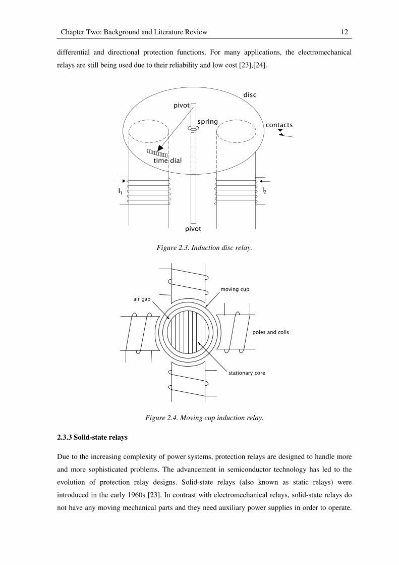
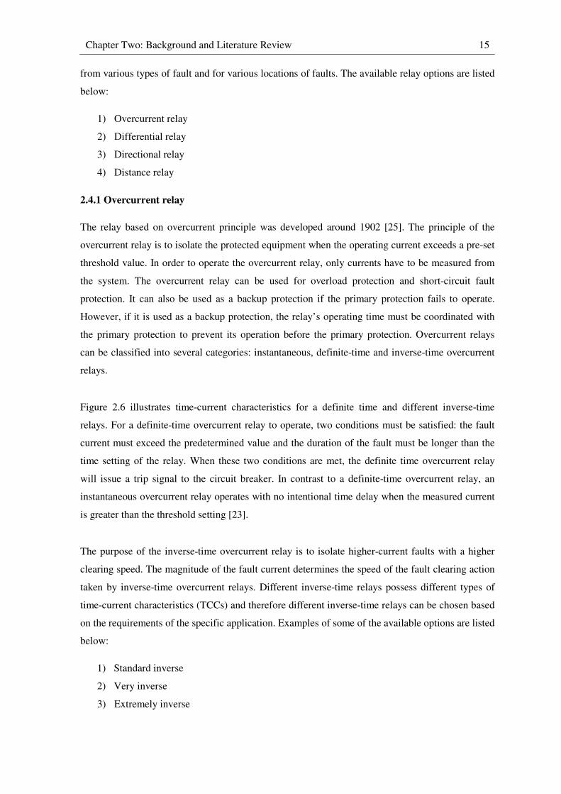
The operating principle of the induction-type relays is similar to the single-phase AC motor. Figure
2.3 illustrates an induction disc relay. Figure 2.4 illustrates a moving cup induction relay. The
electromagnetic field produced by the magnetic poles will induce eddy currents in the moving
element (either the disc or cup). The field on the moving element produced by the eddy currents
tries to align with the field produced by the coils, which causes rotational movement. The angle of
rotation required for the movable contact to reach the fixed contact is adjusted by the time lever.
The time required for the relay to trip is hence determined by the time lever. The induction-type
electromechanical relays can be configured for different applications such as overcurrent, distance,
Chapter Two: Background and Literature Review 12
differential and directional protection functions. For many applications, the electromechanical
relays are still being used due to their reliability and low cost [23],[24].
Figure 2.3. Induction disc relay.
Figure 2.4. Moving cup induction relay.
2.3.3 Solid-state relays
Due to the increasing complexity of power systems, protection relays are designed to handle more
and more sophisticated problems. The advancement in semiconductor technology has led to the
evolution of protection relay designs. Solid-state relays (also known as static relays) were
introduced in the early 1960s [23]. In contrast with electromechanical relays, solid-state relays do
not have any moving mechanical parts and they need auxiliary power supplies in order to operate.
time dial
disc
pivot
I
contactsspring
1I2
pivot
air gap
moving cup
poles and coils
stationary core

Chapter Two: Background and Literature Review 13
Solid-state relays consist of two main circuitries: digital logic circuits for logical variable
operations and analogue circuits for both measuring circuits and fault sensing. The intention of the
solid-state relay development was to replace electromechanical relays; therefore all the
characteristics associated with existing electromechanical relays can be implemented using solid-
state relays [24]. However, while the characteristics of a particular type of electromechanical relay
are fixed, in solid-state relays, these characteristics can be modified. Solid-state relays have higher
accuracy and faster operating speed than electromechanical relays. The reduced size of solid-state
relays is one of their advantages since less mounting space is required; they also do not have to be
mounted in a certain orientation compared to electromechanical relays. Solid-state relays also have
better immunity against dust and vibration, but higher electromagnetic interference susceptibility is
one of their disadvantages, and therefore shielding is required in the installation. Solid-state relays
are very sensitive to environmental factors such as humidity and temperature and therefore their
operating ranges are narrower than those of electromechanical relays [23],[24].
2.3.4 Digital microprocessor-based relays
The concept of using digital devices to perform protection functions was proposed by George
Rockefeller in 1969 [23]. However, the concept was not realized due to the high cost of the digital
computer at the time. The limited processing power of early digital computers was another reason
to initially discard the concept of digital relay implementation. However, subsequent development
of faster digital computers and microprocessors led to a re-evaluation of George Rockefeller’s
concept on implementation of the digital relay. The price for both digital computers and the
associated memory chips has decreased significantly due to maturity of the technology. As a result,
microprocessor-based relays became commercially available in the 1980s. These microprocessor-
based relays are distinct from the other types of relays since they are fully implemented using
digital technology. The reliability of the protection system can be improved by using digital relays
since their status can be monitored. The programmable nature of their functions is another
important feature of digital relays: many different relay characteristics can be provided within one
device so that the protection engineer can select different characteristics and modify them for
different applications without changing the physical device. Because the processing power of
available microprocessors increases over time, more sophisticated algorithms can be implemented
on digital relays as the technology advances. Digital relays also have the ability to record the data
measured on the power system. This is a significant advantage for protection engineers since the
recorded data can be used for system dynamic study or fault analysis. Modern digital relays are
more versatile than earlier microprocessor-based relays and therefore they are also being referred to
as Intelligent Electronic Devices (IEDs) rather than simple protective relays. These digital relays
also have the ability to communicate with each other and hence allow a better coordination
between their protective functions [23].

Chapter Two: Background and Literature Review 14
Figure 2.5 illustrates a functional block diagram of a digital relay. The inputs to the digital relay
are analogue quantities measured from the power system. The analogue quantities at the input to
the digital relay are digitized or sampled by an analogue-to-digital (A/D) converter at a sampling
frequency that can vary from 240 Hz to 2 kHz (between, approximately, 4 to 40 samples per cycle
of the power system’s AC waveforms). The sampled data remains in the device’s scratchpad,
which is the Random Access Memory (RAM), for the Central Processing Unit (CPU) to process.
Digital filters are used to filter out the unwanted noise in the sampled data. The comparison
between the sampled data and the threshold values is done in the relay logic and a decision is made
based on the result of the comparison. The outcome is sent to the circuit breaker in order to control
the circuit breaker. The status of the circuit breaker is also often monitored by the digital relay [23].
Figure 2.5. Functional block diagram of a digital relay.
2.4 Protection relay principles
This section provides a broad overview of different protective relaying principles. Different relays
have different characteristics and hence are intended to be used for different applications. The same
protective function can often be implemented by using different relays, and therefore an
understanding of different relay characteristics is very important. Often the same piece of plant (e.g.
generator and transformer, etc.) is protected by more than one type of relay or more than one type
of element in one relay at the same time for various reasons. If there is more than one relay in the
protection system, the reliability of the protection system as a whole will not be compromised if the
primary protection relay fails to operate correctly since there is backup protection available in the
protection scheme from other relays. In some applications, especially generator protection,
different relay characteristics are required in order to provide complete protection for the plant
Power System Signals
Analog Input Subsystem
Digital Input Subsystem
Digital Output Subsystem
DataScratchpad
Relay Logic
Digital Filter
HistoricalData File
RelaySettings
PowerSupply
Digital relay
Chapter Two: Background and Literature Review 15
from various types of fault and for various locations of faults. The available relay options are listed
below:
1) Overcurrent relay
2) Differential relay
3) Directional relay
4) Distance relay
2.4.1 Overcurrent relay
The relay based on overcurrent principle was developed around 1902 [25]. The principle of the
overcurrent relay is to isolate the protected equipment when the operating current exceeds a pre-set
threshold value. In order to operate the overcurrent relay, only currents have to be measured from
the system. The overcurrent relay can be used for overload protection and short-circuit fault
protection. It can also be used as a backup protection if the primary protection fails to operate.
However, if it is used as a backup protection, the relay’s operating time must be coordinated with
the primary protection to prevent its operation before the primary protection. Overcurrent relays
can be classified into several categories: instantaneous, definite-time and inverse-time overcurrent
relays.
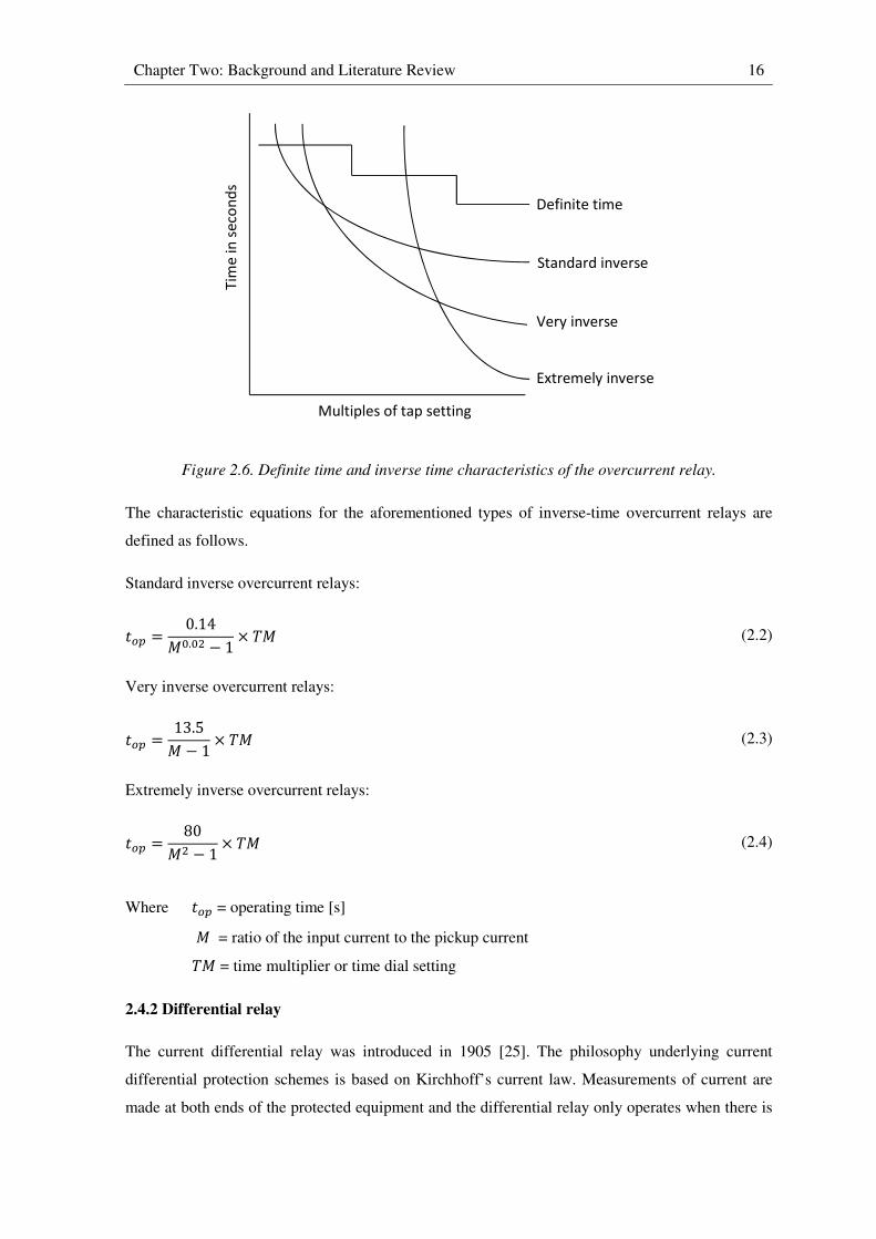
Figure 2.6 illustrates time-current characteristics for a definite time and different inverse-time
relays. For a definite-time overcurrent relay to operate, two conditions must be satisfied: the fault
current must exceed the predetermined value and the duration of the fault must be longer than the
time setting of the relay. When these two conditions are met, the definite time overcurrent relay
will issue a trip signal to the circuit breaker. In contrast to a definite-time overcurrent relay, an
instantaneous overcurrent relay operates with no intentional time delay when the measured current
is greater than the threshold setting [23].
The purpose of the inverse-time overcurrent relay is to isolate higher-current faults with a higher
clearing speed. The magnitude of the fault current determines the speed of the fault clearing action
taken by inverse-time overcurrent relays. Different inverse-time relays possess different types of
time-current characteristics (TCCs) and therefore different inverse-time relays can be chosen based
on the requirements of the specific application. Examples of some of the available options are listed
below:
1) Standard inverse
2) Very inverse
3) Extremely inverse
Chapter Two: Background and Literature Review 16
Figure 2.6. Definite time and inverse time characteristics of the overcurrent relay.
The characteristic equations for the aforementioned types of inverse-time overcurrent relays are
defined as follows.
Standard inverse overcurrent relays:
�� = 0.14��.�� − 1 × �� (2.2)
Very inverse overcurrent relays:
�� = 13.5� − 1 × �� (2.3)
Extremely inverse overcurrent relays:
�� = 80�� − 1 × �� (2.4)
Where �� = operating time [s]
� = ratio of the input current to the pickup current
�� = time multiplier or time dial setting
2.4.2 Differential relay
The current differential relay was introduced in 1905 [25]. The philosophy underlying current
differential protection schemes is based on Kirchhoff’s current law. Measurements of current are
made at both ends of the protected equipment and the differential relay only operates when there is
Tim
e i
n s
eco
nd
s
Multiples of tap setting
Extremely inverse
Very inverse
Standard inverse
Definite time
Chapter Two: Background and Literature Review 17
a difference in current entering and leaving the device. In practice, the differential current (also
known as the operating current) must exceed a small set threshold value of current. The differential
relay can only detect faults within the specific equipment being protected and it cannot be used as
backup protection for other equipment therefore it is often referred to as unit protection.
2.4.3 Directional relay
The directional relay was developed in 1909 [25]. The directional relay is designed to respond to
the relative phase angle between a current and another current or voltage reference [23]. A
directional relay is typically used in conjunction with some other form of relay such as an
overcurrent relay or a distance relay. The use of a directional relay together with an overcurrent
relay or a distance relay does not change the original characteristics of either of these relays but
rather it provides an additional feature for these relays: because a directional relay has the ability to
sense the direction of the power flow at a specific location, it can add selectivity to these forms of
protection so that the overcurrent or distance relay then responds only to faults in one direction
relative to the relay (forward or reverse). A directional relay requires a reasonably constant
reference quantity (also known as the polarizing quantity). During a fault, the phase angle of the
system voltages does not change significantly, whereas the phase angle of the line current can
undergo significant changes of up to 180°. Therefore in most applications, system voltages are used
as a reference quantity [21].
2.4.4 Distance relay
The distance relay was developed in 1923 [25]. In distance relaying, the voltage and current
measured from the system are used to determine the total impedance seen by the relay. The relay
operates when the impedance seen by the relay is less than its threshold setting.
Figure 2.7. Offset mho and quadrilateral tripping characteristics.
X
R0
X
R0
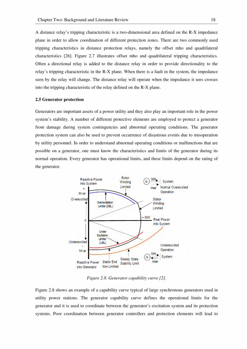
Chapter Two: Background and Literature Review 18
A distance relay’s tripping characteristic is a two-dimensional area defined on the R-X impedance
plane in order to allow coordination of different protection zones. There are two commonly used
tripping characteristics in distance protection relays, namely the offset mho and quadrilateral
characteristics [26]. Figure 2.7 illustrates offset mho and quadrilateral tripping characteristics.
Often a directional relay is added to the distance relay in order to provide directionality to the
relay’s tripping characteristic in the R-X plane. When there is a fault in the system, the impedance
seen by the relay will change. The distance relay will operate when the impedance it sees crosses
into the tripping characteristic of the relay defined on the R-X plane.
2.5 Generator protection
Generators are important assets of a power utility and they also play an important role in the power
system’s stability. A number of different protective elements are employed to protect a generator
from damage during system contingencies and abnormal operating conditions. The generator
protection system can also be used to prevent occurrence of disastrous events due to misoperation
by utility personnel. In order to understand abnormal operating conditions or malfunctions that are
possible on a generator, one must know the characteristics and limits of the generator during its
normal operation. Every generator has operational limits, and these limits depend on the rating of
the generator.
Figure 2.8. Generator capability curve [2].
Figure 2.8 shows an example of a capability curve typical of large synchronous generators used in
utility power stations. The generator capability curve defines the operational limits for the
generator and it is used to coordinate between the generator’s excitation system and its protection
systems. Poor coordination between generator controllers and protection elements will lead to
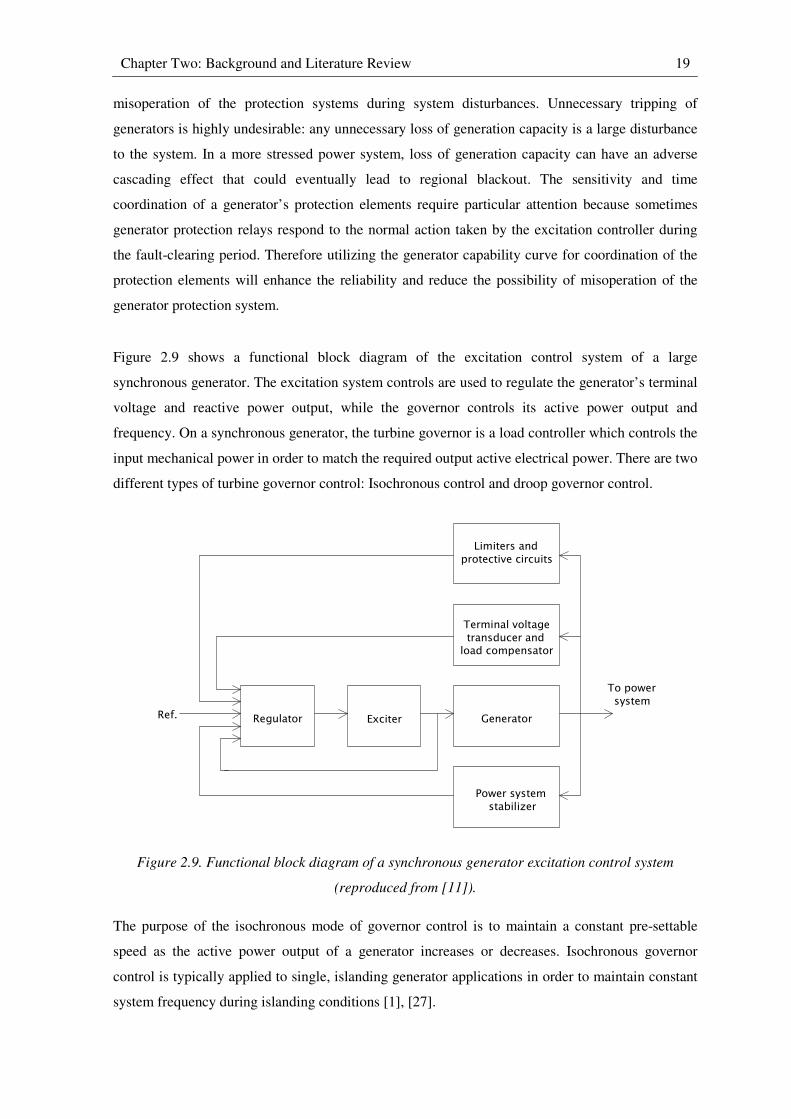
Chapter Two: Background and Literature Review 19
misoperation of the protection systems during system disturbances. Unnecessary tripping of
generators is highly undesirable: any unnecessary loss of generation capacity is a large disturbance
to the system. In a more stressed power system, loss of generation capacity can have an adverse
cascading effect that could eventually lead to regional blackout. The sensitivity and time
coordination of a generator’s protection elements require particular attention because sometimes
generator protection relays respond to the normal action taken by the excitation controller during
the fault-clearing period. Therefore utilizing the generator capability curve for coordination of the
protection elements will enhance the reliability and reduce the possibility of misoperation of the
generator protection system.
Figure 2.9 shows a functional block diagram of the excitation control system of a large
synchronous generator. The excitation system controls are used to regulate the generator’s terminal
voltage and reactive power output, while the governor controls its active power output and
frequency. On a synchronous generator, the turbine governor is a load controller which controls the
input mechanical power in order to match the required output active electrical power. There are two
different types of turbine governor control: Isochronous control and droop governor control.
Figure 2.9. Functional block diagram of a synchronous generator excitation control system
(reproduced from [11]).
The purpose of the isochronous mode of governor control is to maintain a constant pre-settable
speed as the active power output of a generator increases or decreases. Isochronous governor
control is typically applied to single, islanding generator applications in order to maintain constant
system frequency during islanding conditions [1], [27].
Terminal voltage transducer andload compensator
Exciter
Limiters andprotective circuits
Generator
Power system stabilizer
To power system
RegulatorRef.
Chapter Two: Background and Literature Review 20
If the governor control is set to droop mode, an increase in active power output of the generator
will lead to a linear decrease in generator speed. This mode of governor control is typically applied
to generators that are connected to the power system in order to regulate their speed versus load
characteristic. If all generators have the same droop setting, they will share load proportional to
their full load capacity [1],[27]. This control topology can avoid excessive loading and unloading
between the interconnected generators when they are operating in parallel.
2.5.1 Generator excitation systems
The purpose of the excitation system is to provide the current needed to establish the rotor
magnetic field so as to maintain the generator in synchronism. In so doing the excitation system
also determines the amount of reactive power to be generated or absorbed at the generator AC
terminals. There are many different types of excitation system: DC excitation, AC excitation and
static excitation systems [11]. Automatic voltage regulation (AVR), constant power factor
regulation, and constant reactive power regulation are the options available for the excitation
control [1]. As mentioned previously, different generators have different capabilities and therefore
their operational limits are different. There are different limiters that restrict the excitation
controller in order to avoid operation beyond the generator’s capabilities.
The purpose of the overexcitation limiter (OEL) is to prevent a prolonged excess of excitation
current supply to the generator field [28]; however, brief overcurrent is allowed and is highly
desirable on the field in order to maintain stability after faults. A prolonged overload condition
must be avoided since it will cause insulation deterioration due to thermal damage and hence lead
to insulation failure. Misoperation of the field protection may occur if the overexcitation limiter is
not properly coordinated with the field protection.
The function of the underexcitation limiter (UEL) is to prevent heating of the stator end region
during the underexcitation operation. It also prevents the excitation current commanded by the
automatic voltage regulator from reducing to a level where the loss-of-field protection operates
[28], as well as preventing the generator from losing synchronism due to insufficient synchronizing
torque.
From the above mentioned excitation limiters, one can see the importance of the coordination
between the excitation limiters and the generator protection elements. Misoperation of the
generator protection system may be a result of the poor coordination between the excitation limiters
and the generator protection elements.
Chapter Two: Background and Literature Review 21
2.5.2 Generator grounding scheme
In practice, there are many grounding schemes available to ground a generator. The particular
generator grounding scheme used will be chosen based on the following factors: cost of the
grounding scheme, implementation complexity and the rating of the generator.
The grounding schemes can be classified into the following categories:
1) Ungrounded
2) Solidly grounded
3) Low-impedance grounded
4) High-impedance grounded
For an ungrounded generator, there is no physical connection between the generator neutral and the
system ground. During a stator winding to ground (stator-ground) fault, there will be a small flow
of fault current as a result of the shunt capacitance between the stator windings and ground. The
ground fault current is not a concern in the case of the ungrounded generator; however the
overvoltage will be a threat [29]. Therefore it is not recommended to implement this grounding
scheme for a generator due to the overvoltage condition encountered during a ground fault on the
generator stator winding.
A solidly grounded generator has a physical connection between the generator neutral and the
system ground. There will be no other resistor or reactor inserted between the generator neutral and
the system ground except for an earthing conductor. A stator-ground fault that occurs under this
grounding configuration will produce a large ground fault current [29].
Low-impedance generator grounding can be classified into two types: low-resistance or low-
reactance grounding configuration. A resistor or a reactor with low-ohmic value is usually used for
the connection between the generator neutral and the system ground for this grounding scheme.
The resistor value for a low-resistance grounding scheme is selected to limit the current through the
neutral resistor to 1.5 times nominal generator rated current during a stator-ground fault [29].
Where this form of grounding scheme is used, either a ground differential protection or phase
percentage differential protection scheme is usually implemented to protect the generator stator
windings.
High-impedance grounding schemes can also be classified into two types: high-resistance or high-
reactance grounding configuration. There are different practical ways to implement this type of
grounding scheme. A resistor with high-ohmic value can be inserted directly between the generator
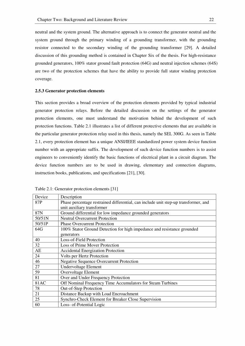
Chapter Two: Background and Literature Review 22
neutral and the system ground. The alternative approach is to connect the generator neutral and the
system ground through the primary winding of a grounding transformer, with the grounding
resistor connected to the secondary winding of the grounding transformer [29]. A detailed
discussion of this grounding method is contained in Chapter Six of the thesis. For high-resistance
grounded generators, 100% stator ground fault protection (64G) and neutral injection schemes (64S)
are two of the protection schemes that have the ability to provide full stator winding protection
coverage.
2.5.3 Generator protection elements
This section provides a broad overview of the protection elements provided by typical industrial
generator protection relays. Before the detailed discussion on the settings of the generator
protection elements, one must understand the motivation behind the development of such
protection functions. Table 2.1 illustrates a list of different protective elements that are available in
the particular generator protection relay used in this thesis, namely the SEL 300G. As seen in Table
2.1, every protection element has a unique ANSI/IEEE standardized power system device function
number with an appropriate suffix. The development of such device function numbers is to assist
engineers to conveniently identify the basic functions of electrical plant in a circuit diagram. The
device function numbers are to be used in drawing, elementary and connection diagrams,
instruction books, publications, and specifications [21], [30].
Table 2.1: Generator protection elements [31]
Device Description
87P Phase percentage restrained differential, can include unit step-up transformer, and
unit auxiliary transformer
87N Ground differential for low impedance grounded generators
50/51N Neutral Overcurrent Protection
50/51P Phase Overcurrent Protection
64G 100% Stator Ground Detection for high impedance and resistance grounded
generators
40 Loss-of-Field Protection
32 Loss of Prime Mover Protection
AE Accidental Energization Protection
24 Volts per Hertz Protection
46 Negative Sequence Overcurrent Protection
27 Undervoltage Element
59 Overvoltage Element
81 Over and Under Frequency Protection
81AC Off Nominal Frequency Time Accumulators for Steam Turbines
78 Out-of-Step Protection
21 Distance Backup with Load Encroachment
25 Synchro-Check Element for Breaker Close Supervision
60 Loss- of-Potential Logic
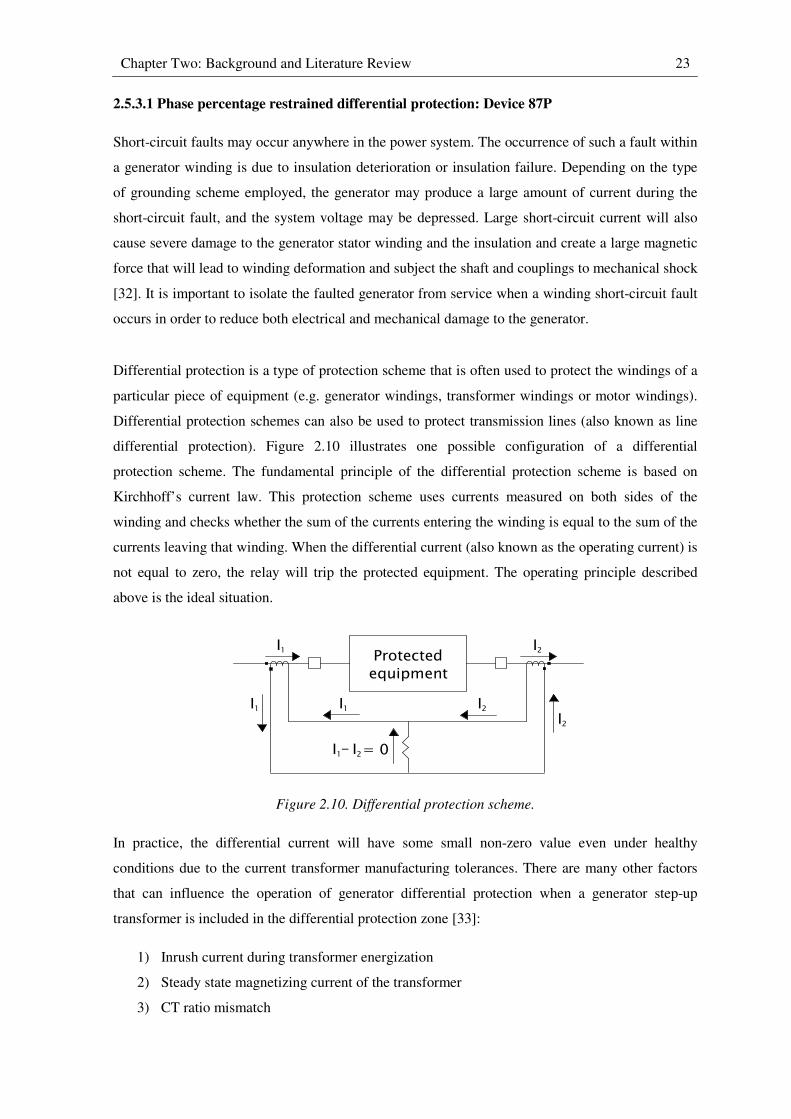
Chapter Two: Background and Literature Review 23
2.5.3.1 Phase percentage restrained differential protection: Device 87P
Short-circuit faults may occur anywhere in the power system. The occurrence of such a fault within
a generator winding is due to insulation deterioration or insulation failure. Depending on the type
of grounding scheme employed, the generator may produce a large amount of current during the
short-circuit fault, and the system voltage may be depressed. Large short-circuit current will also
cause severe damage to the generator stator winding and the insulation and create a large magnetic
force that will lead to winding deformation and subject the shaft and couplings to mechanical shock
[32]. It is important to isolate the faulted generator from service when a winding short-circuit fault
occurs in order to reduce both electrical and mechanical damage to the generator.
Differential protection is a type of protection scheme that is often used to protect the windings of a
particular piece of equipment (e.g. generator windings, transformer windings or motor windings).
Differential protection schemes can also be used to protect transmission lines (also known as line
differential protection). Figure 2.10 illustrates one possible configuration of a differential
protection scheme. The fundamental principle of the differential protection scheme is based on
Kirchhoff’s current law. This protection scheme uses currents measured on both sides of the
winding and checks whether the sum of the currents entering the winding is equal to the sum of the
currents leaving that winding. When the differential current (also known as the operating current) is
not equal to zero, the relay will trip the protected equipment. The operating principle described
above is the ideal situation.
Figure 2.10. Differential protection scheme.
In practice, the differential current will have some small non-zero value even under healthy
conditions due to the current transformer manufacturing tolerances. There are many other factors
that can influence the operation of generator differential protection when a generator step-up
transformer is included in the differential protection zone [33]:
1) Inrush current during transformer energization
2) Steady state magnetizing current of the transformer
3) CT ratio mismatch
Protected equipment
I I1 2
I1I2
I1 I2
I1 I2- = 0
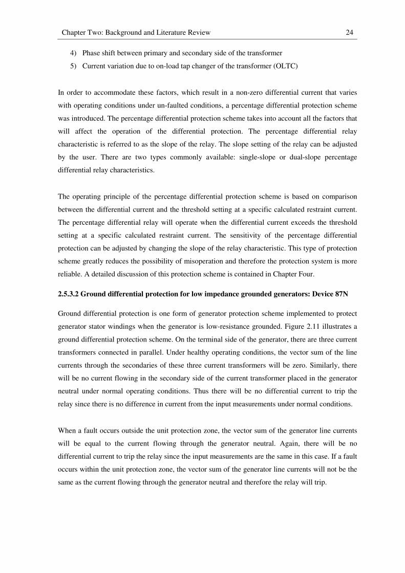
Chapter Two: Background and Literature Review 24
4) Phase shift between primary and secondary side of the transformer
5) Current variation due to on-load tap changer of the transformer (OLTC)
In order to accommodate these factors, which result in a non-zero differential current that varies
with operating conditions under un-faulted conditions, a percentage differential protection scheme
was introduced. The percentage differential protection scheme takes into account all the factors that
will affect the operation of the differential protection. The percentage differential relay
characteristic is referred to as the slope of the relay. The slope setting of the relay can be adjusted
by the user. There are two types commonly available: single-slope or dual-slope percentage
differential relay characteristics.
The operating principle of the percentage differential protection scheme is based on comparison
between the differential current and the threshold setting at a specific calculated restraint current.
The percentage differential relay will operate when the differential current exceeds the threshold
setting at a specific calculated restraint current. The sensitivity of the percentage differential
protection can be adjusted by changing the slope of the relay characteristic. This type of protection
scheme greatly reduces the possibility of misoperation and therefore the protection system is more
reliable. A detailed discussion of this protection scheme is contained in Chapter Four.
2.5.3.2 Ground differential protection for low impedance grounded generators: Device 87N
Ground differential protection is one form of generator protection scheme implemented to protect
generator stator windings when the generator is low-resistance grounded. Figure 2.11 illustrates a
ground differential protection scheme. On the terminal side of the generator, there are three current
transformers connected in parallel. Under healthy operating conditions, the vector sum of the line
currents through the secondaries of these three current transformers will be zero. Similarly, there
will be no current flowing in the secondary side of the current transformer placed in the generator
neutral under normal operating conditions. Thus there will be no differential current to trip the
relay since there is no difference in current from the input measurements under normal conditions.
When a fault occurs outside the unit protection zone, the vector sum of the generator line currents
will be equal to the current flowing through the generator neutral. Again, there will be no
differential current to trip the relay since the input measurements are the same in this case. If a fault
occurs within the unit protection zone, the vector sum of the generator line currents will not be the
same as the current flowing through the generator neutral and therefore the relay will trip.
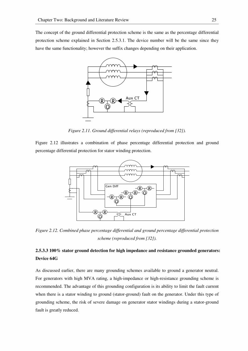
Chapter Two: Background and Literature Review 25
The concept of the ground differential protection scheme is the same as the percentage differential
protection scheme explained in Section 2.5.3.1. The device number will be the same since they
have the same functionality; however the suffix changes depending on their application.
Figure 2.11. Ground differential relays (reproduced from [32]).
Figure 2.12 illustrates a combination of phase percentage differential protection and ground
percentage differential protection for stator winding protection.
Figure 2.12. Combined phase percentage differential and ground percentage differential protection
scheme (reproduced from [32]).
2.5.3.3 100% stator ground detection for high impedance and resistance grounded generators:
Device 64G
As discussed earlier, there are many grounding schemes available to ground a generator neutral.
For generators with high MVA rating, a high-impedance or high-resistance grounding scheme is
recommended. The advantage of this grounding configuration is its ability to limit the fault current
when there is a stator winding to ground (stator-ground) fault on the generator. Under this type of
grounding scheme, the risk of severe damage on generator stator windings during a stator-ground
fault is greatly reduced.
OR R
Aux CT
OR R O
R R OR R
OR R
Gen Diff
Aux CT
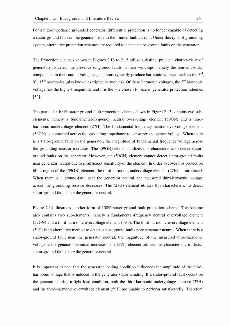
Chapter Two: Background and Literature Review 26
For a high-impedance grounded generator, differential protection is no longer capable of detecting
a stator-ground fault on the generator due to the limited fault current. Under this type of grounding
system, alternative protection schemes are required to detect stator-ground faults on the generator.
The Protection schemes shown in Figures 2.13 to 2.15 utilize a distinct practical characteristic of
generators to detect the presence of ground faults in their windings, namely the non-sinusoidal
components in their output voltages: generators typically produce harmonic voltages such as the 3rd
,
9th, 15
th harmonics (also known as triplen harmonics). Of these harmonic voltages, the 3
rd harmonic
voltage has the highest magnitude and it is the one chosen for use in generator protection schemes
[32].
The particular 100% stator ground fault protection scheme shown in Figure 2.13 contains two sub-
elements, namely a fundamental-frequency neutral overvoltage element (59GN) and a third-
harmonic undervoltage element (27H). The fundamental-frequency neutral overvoltage element
(59GN) is connected across the grounding impedance to sense zero-sequence voltage. When there
is a stator-ground fault on the generator, the magnitude of fundamental frequency voltage across
the grounding resistor increases. The (59GN) element utilizes this characteristic to detect stator-
ground faults on the generator. However, the (59GN) element cannot detect stator-ground faults
near generator neutral due to insufficient sensitivity of the element. In order to cover this protection
blind region of the (59GN) element, the third harmonic undervoltage element (27H) is introduced.
When there is a ground-fault near the generator neutral, the measured third-harmonic voltage
across the grounding resistor decreases. The (27H) element utilizes this characteristic to detect
stator-ground faults near the generator neutral.
Figure 2.14 illustrates another form of 100% stator ground fault protection scheme. This scheme
also contains two sub-elements, namely a fundamental-frequency neutral overvoltage element
(59GN) and a third-harmonic overvoltage element (59T). The third-harmonic overvoltage element
(59T) is an alternative method to detect stator-ground faults near generator neutral. When there is a
stator-ground fault near the generator neutral, the magnitude of the measured third-harmonic
voltage at the generator terminal increases. The (59T) element utilizes this characteristic to detect
stator-ground faults near the generator neutral.
It is important to note that the generator loading condition influences the amplitude of the third-
harmonic voltage that is induced in the generator stator winding. If a stator-ground fault occurs on
the generator during a light load condition, both the third-harmonic undervoltage element (27H)
and the third-harmonic overvoltage element (59T) are unable to perform satisfactorily. Therefore
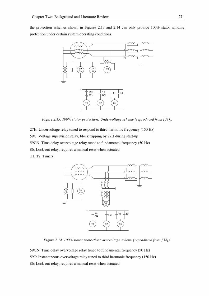
Chapter Two: Background and Literature Review 27
the protection schemes shown in Figures 2.13 and 2.14 can only provide 100% stator winding
protection under certain system operating conditions.
Figure 2.13. 100% stator protection: Undervoltage scheme (reproduced from [34]).
27H: Undervoltage relay tuned to respond to third-harmonic frequency (150 Hz)
59C: Voltage supervision relay, block tripping by 27H during start-up
59GN: Time delay overvoltage relay tuned to fundamental frequency (50 Hz)
86: Lock-out relay, requires a manual reset when actuated
T1, T2: Timers
Figure 2.14. 100% stator protection: overvoltage scheme (reproduced from [34]).
59GN: Time delay overvoltage relay tuned to fundamental frequency (50 Hz)
59T: Instantaneous overvoltage relay tuned to third harmonic frequency (150 Hz)
86: Lock-out relay, requires a manual reset when actuated
59GN
27 H
59 C
T1 T2 86
59GN27H
59C T1 T2
+
-
59GN
T1 T2 86
T1 T2
+
-
59 T
59GN
59T

Chapter Two: Background and Literature Review 28
Figure 2.15. Third-harmonic voltage differential scheme (reproduced from [34]).
59GN: Time delay overvoltage relay tuned to fundamental frequency (50 Hz)
59D: Instantaneous third-harmonic voltage differential relay
Figure 2.15 illustrates another form of 100% stator ground fault protection scheme. This protection
scheme contains two sub-elements, namely a fundamental-frequency neutral overvoltage element
(59GN) and an instantaneous third-harmonic voltage differential element (59D). The ratio between
the third-harmonic terminal voltage and the third-harmonic neutral voltage of a generator should
remain the same during normal operation, but the ratio changes when a stator-ground fault occurs.
The instantaneous third-harmonic voltage differential element (59D) uses this characteristic to
detect stator-ground faults on the generator. Unlike the third-harmonic undervoltage element (27H)
and third-harmonic overvoltage element (59T), the (59D) element can detect stator-ground faults
on a generator under various generator loading conditions. A detailed discussion of this particular
protection scheme is contained in Chapter Six.
Figure 2.16 illustrates a neutral injection scheme (device: 64S) which is an alternative option to
provide 100% stator winding protection [35]. This protection scheme utilizes an injection
transformer in order to apply an AC voltage signal to the neutral. The injection transformer is in
series with the grounding transformer. The injected AC voltage signal is usually at a sub-harmonic
of the normal system frequency. The magnitude of the sub-harmonic current will be determined by
the overall system impedance. An overcurrent relay is tuned to monitor this sub-harmonic current
in the neutral circuit. When there is a stator ground fault, the winding capacitance will be bypassed
and hence the overall system impedance decreases. The sub-harmonic current increases as a result
of the reduction of the overall system impedance. The overcurrent relay will operate when the sub-
harmonic current increases to a level that exceeds the threshold setting [32]. An alternative way to
detect stator-ground faults is to calculate the resultant impedance using the subharmonic injection
voltage and current, and to compare this impedance with a threshold setting [35].
59GN
150 Hz Pass
150 Hz Pass
59D
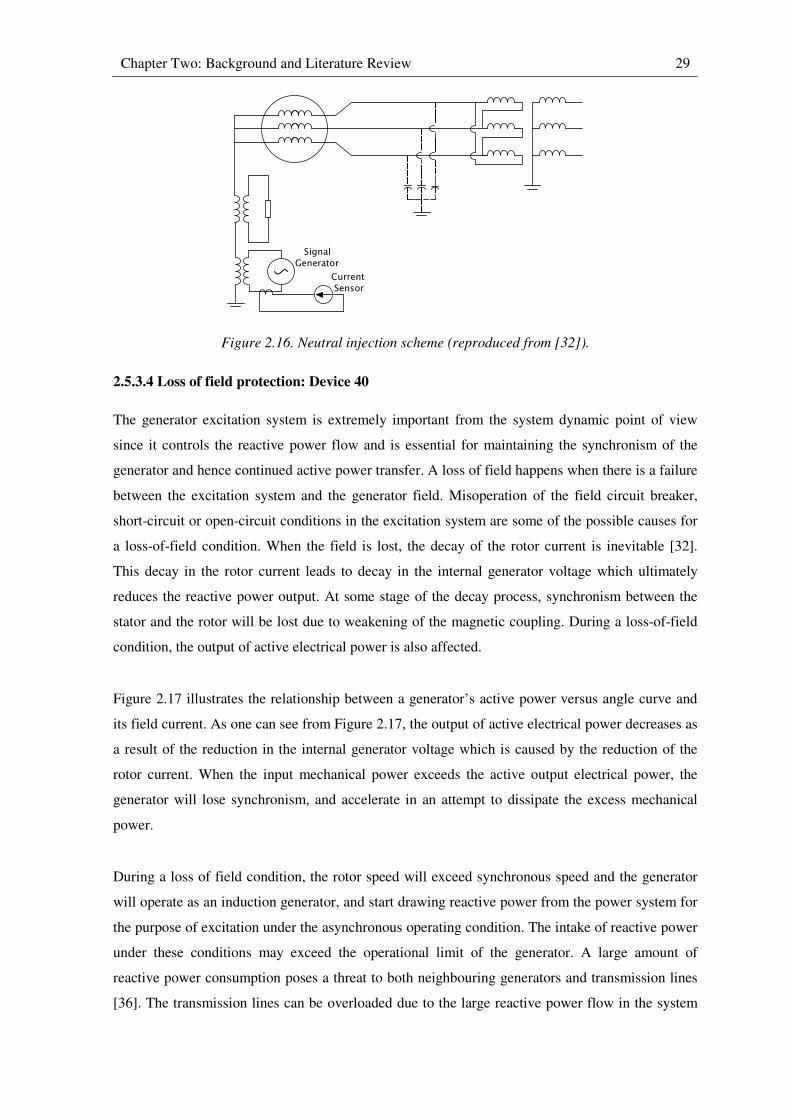
Chapter Two: Background and Literature Review 29
Figure 2.16. Neutral injection scheme (reproduced from [32]).
2.5.3.4 Loss of field protection: Device 40
The generator excitation system is extremely important from the system dynamic point of view
since it controls the reactive power flow and is essential for maintaining the synchronism of the
generator and hence continued active power transfer. A loss of field happens when there is a failure
between the excitation system and the generator field. Misoperation of the field circuit breaker,
short-circuit or open-circuit conditions in the excitation system are some of the possible causes for
a loss-of-field condition. When the field is lost, the decay of the rotor current is inevitable [32].
This decay in the rotor current leads to decay in the internal generator voltage which ultimately
reduces the reactive power output. At some stage of the decay process, synchronism between the
stator and the rotor will be lost due to weakening of the magnetic coupling. During a loss-of-field
condition, the output of active electrical power is also affected.
Figure 2.17 illustrates the relationship between a generator’s active power versus angle curve and
its field current. As one can see from Figure 2.17, the output of active electrical power decreases as
a result of the reduction in the internal generator voltage which is caused by the reduction of the
rotor current. When the input mechanical power exceeds the active output electrical power, the
generator will lose synchronism, and accelerate in an attempt to dissipate the excess mechanical
power.
During a loss of field condition, the rotor speed will exceed synchronous speed and the generator
will operate as an induction generator, and start drawing reactive power from the power system for
the purpose of excitation under the asynchronous operating condition. The intake of reactive power
under these conditions may exceed the operational limit of the generator. A large amount of
reactive power consumption poses a threat to both neighbouring generators and transmission lines
[36]. The transmission lines can be overloaded due to the large reactive power flow in the system
SignalGenerator
Current Sensor

Chapter Two: Background and Literature Review 30
and the overloaded condition may cause the transmission lines to be tripped. The neighbouring
generators will have to increase their excitation to maximum capacity (as known as ceiling
excitation) in order to support the large amount of reactive power consumption. However, the
generator field will suffer from thermal damage if a prolonged excess of excitation current is
supplied to the field continuously. If the system fails to support the required reactive power, the
system voltage will collapse.
Figure 2.17. Power angle curves at different field currents.
High stator current, rotor damage, torque pulsation and end-core heating are the concerns that arise
in generators operating with loss of field conditions [32]. Some irreversible damages can occur
from the above described phenomena. Therefore extensive asynchronous operation is undesirable
and generators suffering a loss-of-field condition should be isolated before it leads to excessive
damage on the generator and system wide instability [37].
Loss-of-field protection must be able to identify faults properly and also coordinate with the normal
generator controller operations. The tripping characteristic of a loss-of-field protection scheme is a
two-dimensional area defined on an R-X impedance plane. A directional-distance relay is typically
used for loss-of-field protection since it can discriminate between sudden loss of excitation and
purposely reduced excitation [34]. A detailed discussion of loss-of-field protection is contained in
Chapter Four.
2.5.3.5 Out-of-step protection: Device 78
Power systems are quite often subjected to transient disturbances. These transient disturbances such
as major load switching or faults may cause an out-of-step condition between two interconnected
systems. During an out-of-step condition, generator stator windings may be damaged due to
40%
FL
60%
FL
80% FL
Field current = 100% FL
Mechanical
Power
Po
wer
(P
U)
1
Power angle (degrees) 180 0

Chapter Two: Background and Literature Review 31
winding stresses caused by high peak currents and off-nominal frequency operation. The
mechanical structure of a generator and its shaft may also be damaged due to excited mechanical
resonances caused by pulsating torques [11],[32],[34]. A generator or a group of generators that has
pole slipped must be isolated from the rest of the system in order to maintain the integrity and
stability of the system, as well as for the protection of the generator itself.
In the past, the electrical centre during an out-of-step condition was usually out in the transmission
system. Therefore transmission line relays could detect out-of-step conditions between two
interconnected systems and separate them without the need for tripping generators. However,
system and generator impedance characteristics have changed considerably over the years: system
impedances have decreased significantly due to continuous expansion of transmission systems,
while generator impedances have increased due to improved generator cooling methods [32],[34].
Due to these changes in system and generator impedance characteristics, the electrical centre
during an out-of-step condition can appear in a generator or a generator step up transformer.
Therefore a separate out-of-step protection function is required at the generator terminals to detect
out-of-step conditions when the electrical centres of swings are close to the generator zone. A
detailed discussion of the swing characteristics of a generator during an out-of-step condition is
contained in Chapter Four.
Protection schemes that can be applied for detecting generator out-of-step conditions are essentially
the same as the ones that are applied for detecting transmission line out-of-step conditions. The
tripping characteristic of the various types of out-of-step protection schemes is a two-dimensional
area defined on an R-X impedance plane. Examples of some of the available out-of-step protection
schemes are listed below [38]:
1) Simple mho scheme;
2) Single blinder scheme;
3) Double blinder scheme;
4) Double lens and concentric circle scheme.
A detailed discussion of the single blinder protection scheme is contained in Chapter Four.
2.5.3.6 Volts per hertz protection: Device 24
The volts per hertz protection function on a generator protection relay is provided to protect against
excessive overexcitation of the generator and, optionally, also the generator step up transformer.
An excessive overexcitation condition occurs when the flux levels in the magnetic circuits of the
generator and transformer exceed the design limit, which can result in damage to the equipment. It
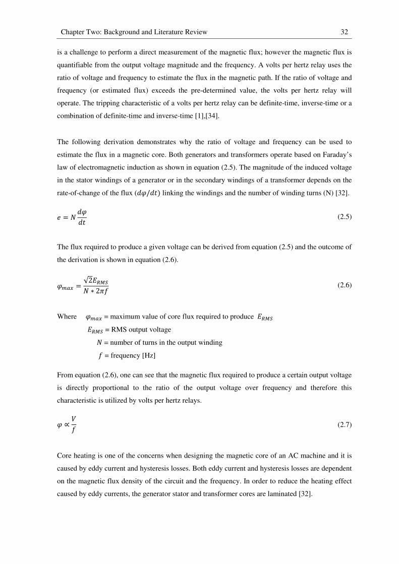
Chapter Two: Background and Literature Review 32
is a challenge to perform a direct measurement of the magnetic flux; however the magnetic flux is
quantifiable from the output voltage magnitude and the frequency. A volts per hertz relay uses the
ratio of voltage and frequency to estimate the flux in the magnetic path. If the ratio of voltage and
frequency (or estimated flux) exceeds the pre-determined value, the volts per hertz relay will
operate. The tripping characteristic of a volts per hertz relay can be definite-time, inverse-time or a
combination of definite-time and inverse-time [1],[34].
The following derivation demonstrates why the ratio of voltage and frequency can be used to
estimate the flux in a magnetic core. Both generators and transformers operate based on Faraday’s
law of electromagnetic induction as shown in equation (2.5). The magnitude of the induced voltage
in the stator windings of a generator or in the secondary windings of a transformer depends on the
rate-of-change of the flux (��/��) linking the windings and the number of winding turns (N) [32].
� = � ���� (2.5)
The flux required to produce a given voltage can be derived from equation (2.5) and the outcome of
the derivation is shown in equation (2.6).
���� = √2"#$%� ∗ 2'( (2.6)
Where ���� = maximum value of core flux required to produce "#$%
"#$% = RMS output voltage
� = number of turns in the output winding
( = frequency [Hz]
From equation (2.6), one can see that the magnetic flux required to produce a certain output voltage
is directly proportional to the ratio of the output voltage over frequency and therefore this
characteristic is utilized by volts per hertz relays.
� ∝ *( (2.7)
Core heating is one of the concerns when designing the magnetic core of an AC machine and it is
caused by eddy current and hysteresis losses. Both eddy current and hysteresis losses are dependent
on the magnetic flux density of the circuit and the frequency. In order to reduce the heating effect
caused by eddy currents, the generator stator and transformer cores are laminated [32].

Chapter Two: Background and Literature Review 33
Eddy current loss: +, = -,(�.�� ��(0/12) (2.8)
Hysteresis loss: +3 = -3(.�4.56�.5(0/12) (2.9)
Excessive flux can be a result of the high output voltage or low operating frequency. Saturation
occurs when there is excessive flux in the magnetic circuit. During normal operation, the magnetic
flux is at its rated, design value and the permeability of the magnetic circuit is higher than that of
the surrounding structures. When saturation of the magnetic circuit occurs, both eddy current and
hysteresis losses will be increased due to the increase in the magnetic flux density. Increase in
losses will lead to increase in temperature of the generator stator and the transformer cores. When
the temperature exceeds the design thermal limit, the inter-lamination insulation material will be
damaged [32]. The increase in core temperature ultimately decreases the permeability of the
magnetic circuit and therefore the excess flux will be spilled into the surrounding structures. The
non-laminated surrounding structures will be subjected to damage due to thermal runaway caused
by induced eddy currents.
One of the main causes of excessive overexcitation on generators and transformers is operation of a
generator unit under automatic voltage regulator control at reduced frequencies during start-up and
shutdown [32],[34]. With the automatic voltage regulator maintaining rated voltage while the
generator is operating at 95% of its rated speed or lower, the ratio of V/Hz at the generator
terminals will be 1.05 pu or greater. Excessive overexcitation can also occur when the feedback
signal from the terminal voltage transducer to the automatic voltage regulator is suddenly lost
[32],[34]. Under this system contingency, the generator terminal voltage seen by the automatic
voltage regulator is zero volts. The regulator will boost the field voltage to its ceiling limit in an
attempt to restore the generator terminal voltage. In this case, ratio of V/Hz is much higher than the
limit as a result of high generator terminal voltage.
2.5.3.7 Negative-sequence overcurrent protection: Device 46
Balanced three-phase loading is the ideal operating condition for a generator. However, it is
difficult to achieve due to the nature of the power system. Open phases, faults and unbalanced
loads are some of the causes of unbalanced loading conditions on a generator [32],[34]. From
symmetrical component representation of unbalanced system conditions, generator stator currents
can be resolved into positive, negative and zero sequence components as shown in equations (2.10)
to (2.12), respectively.

Chapter Two: Background and Literature Review 34
74 = 7� + 78∠120° + 7�∠240°3 (2.10)
7� = 7� + 78∠240° + 7�∠120°3 (2.11)
7� = 7� + 78 + 7�3 (2.12)
The magnetic field produced by the positive sequence generator current74 rotates in the same
direction as the rotor. Both the rotor and the magnetic fields are rotating at the same speed which is
known as synchronous speed. The resultant field retains a fixed position with respect to the rotor
since the speed and direction of rotation of both are the same, and hence there will be no current
induced into the rotor [32].
Negative sequence current7� appears when there is an unbalanced generator loading condition.
Negative sequence current will produce a magnetic field which also rotates at synchronous speed;
however, the direction of rotation is opposite to that of the power system. If negative sequence
current exists, a double-frequency current will be induced into the rotor windings. The double-
frequency currents induced in the rotor can cause a drastic rotor temperature increase in a very
short time. Excessive rotor heating can result in insulation failure or deterioration of mechanical
structures [32].
A generator can accommodate a certain amount of negative sequence current during its operation
without consequences of severe damage. Both the continuous and short-time negative sequence
current capabilities of a generator are clearly defined in [39]. An overcurrent relay is typically
employed to detect negative sequence current that exceeds the defined capability limit of a
generator.
2.5.3.8 Synchronism check relays: Device 25
During normal operation of a power system, generators will be isolated from service from time to
time for maintenance or damage repair work. It is also the case that only some generators run
continuously to supply the base load while the other generators are deployed only during peak load
conditions. When a generator is returning to service, synchronization must be performed. The
purpose of the synchronization is to match the magnitude, frequency and phase of the voltages on
either side of the generator circuit breaker to within the set thresholds. The synchronism check
relay performs a check on the voltage level and the operating frequency on both sides of the open
circuit breaker and makes sure that they are within the acceptable limits before it issues a close
Chapter Two: Background and Literature Review 35
signal for the circuit breaker. The synchronism check is very important when the generator is
returning to service. If the synchronization is not done properly before the closure of the circuit
breaker, it can create large electrical and mechanical transients that can damage the generator,
generator-step-up transformer and prime mover. In order to avoid these electrical and mechanical
transients, the voltage and the frequency should ideally be matched perfectly. However, in practice,
there will be small intentional mismatches, within the allowed tolerances, between the voltage
magnitude and frequency of the generator and those of the system. The frequency of the generator
will be set slightly higher than the system frequency and the generator output voltage will be set
higher and leading the system voltage on the other side of the open circuit breaker. The above
settings ensure that active and reactive power will flow out of the generator upon synchronisation.
This will prevent the generator from operating as a motor due to reverse power flow after closure
of the circuit breaker. The higher generator output voltage will avoid the intake of reactive power
due to voltage dips during the period of synchronization [32].
2.5.3.9 Abnormal voltage protection: Devices 27 & 59
Abnormal voltage protection is provided to prevent the generator from operating beyond its design
limit, and will operate under the following two situations: overvoltage conditions and undervoltage
conditions. The undervoltage condition is not harmful to the generator since it will not cause any
damage to it, but overheating of the auxiliary motors is an adverse effect for the undervoltage
condition. The undervoltage relay is used to prevent extended operation at low voltages in order to
protect the auxiliary motors. When the generator is operated at a voltage level much higher than its
design limit, there will be excessive dielectric stress on the generator which will lead to insulation
failure [1]. An overvoltage relay is used to protect the generator from overvoltage conditions.
2.5.3.10 Abnormal frequency protection: Device 81
The system frequency is 50 Hz under normal operation. The system frequency depends on the
operating speed of the generator.
:; = 120 ∗ (< (2.14)
Where :; = synchronous speed [rpm]
( = system frequency [Hz]
< = number of magnetic poles
The mismatch between the generation of active power and the system load can lead to either
acceleration or deceleration of the generator. Sudden loss of a major load or a transmission facility
leads to the acceleration of the generators. Under this circumstance, mechanical power input to the
Chapter Two: Background and Literature Review 36
generators exceeds the electrical power transferred out of them and the imbalance causes
acceleration of the generator rotors and an increase in the system frequency. When the generation is
less than the system load, the generators will decelerate. This may be caused by sudden loss of
major generation capacity. Under this circumstance, some of the kinetic energy stored in the rotors
of the remaining generators connected to the system is converted to the electrical energy in order to
sustain the system load. Off-frequency operation is not desirable since it will affect many aspects of
the power system. Some of the system loads (i.e. induction motors) are very sensitive to the supply
frequency; therefore any variation in the supply frequency will affect the performance of the loads.
Abnormal frequency operation will also affect these types of sensitive load that are operating
within the power stations themselves and therefore jeopardize the reliability and security of the
entire generation plant [32]. Damage to the generating plant equipment is one of the major
concerns during abnormal frequency operation. For example, the natural frequency of a turbine
blade is designed to be sufficiently removed from rated speed and multiples of rated speed (i.e. the
rated fundamental frequency and its harmonics) so as to avoid mechanical resonances. Excessive
mechanical stress could be exerted on the turbine blades due to mechanical resonances if the
turbine runs at non-rated speeds which could eventually lead to turbine cracking [40].
The National Energy Regulator of South Africa (NERSA) clearly indicates that the acceptable
frequency deviation is ± 2% (± 1 Hz) for the grid network and ± 2.5% (± 1.25 Hz) for an island
network. The limit for maximum frequency deviation is ± 2.5% (± 1.25 Hz) for the grid network
and ± 5% (± 2.5 Hz) for the island network [41].
2.6 Generator modelling
The dynamic equations of synchronous machine windings are normally transformed into a two-axis
(dq) coordinate frame using the Park Transformation [10]. This approach simplifies the structure of
the mathematical model of the synchronous machine significantly. The two-axis form of the
synchronous machine model is quite suitable for power system stability studies; however, it is not
ideally suited to the requirements of most generator protection studies. Although the two-axis
approach to modelling the synchronous machine greatly reduces the structural complexity of the
machine model, certain details on the machine cannot be represented as a result of this
simplification. For instance, generator internal winding faults (i.e. short circuits between the
windings and ground) cannot readily be represented in the simulation model.
On the other hand, the use of a phase-domain dynamic model of the synchronous machine does
allow internal winding faults to be represented more realistically in the simulation model. In the
phase-domain generator model provided in RSCAD, the faulted winding has been included in the
Chapter Two: Background and Literature Review 37
inductance matrix calculation so that short circuits between the windings and ground can be
simulated in the synchronous machine model. Another important feature of this model is that it
allows a detailed electric representation of the external supply to the generator field circuit. In other
words, this model allows the excitation input to the generator to be represented using power system
components so that short circuit and open circuit faults on the excitation system, and even faults
within the power electronics of an exciter, can be represented more realistically.
The phase-domain synchronous machine model has two different approaches for solving its
inductance matrix, namely a two-axis (dq) based approach and a modified winding function
approach [13]. The complete (modified winding function approach) version of the phase-domain
synchronous machine model is capable of representing phase-belt harmonics induced in the
generator stator winding. However, some specific generator details (i.e. the exact distribution of the
stator windings and the actual shape of the rotor-pole arc) are required as inputs to the machine
model when using the modified winding function approach [10]. It is a great challenge to acquire
these specific generator details required for the complete version of the machine model and
therefore only the simplified version (two-axis based approach) is provided in RSCAD for use on
the real-time simulator. The simplified version of this machine model accepts standard parameters
from the two-axis form of the synchronous machine equations rather than requiring knowledge of
the physical geometry of an actual machine. However, this simplified version of the phase-domain
synchronous machine model ignores certain details of the full phase-domain model as it assumes
sinusoidal variation of all inductances with rotor position [10]. As a result, the simplified version of
the machine model does not represent phase-belt harmonics in the generator stator winding, and so
it is not able to represent the third-harmonic voltages in these windings that are relied upon by
some forms of 100% stator ground fault protection scheme to detect stator winding faults. The
simplified version of the phase-domain synchronous machine model that is available [13] does
nevertheless allow internal stator winding faults and external field circuit faults to be represented
accurately, at least with respect to the fundamental frequency behaviour of the generator variables.
With additional modelling effort, it may be possible to supplement the characteristics of this
simplified version of the faulted synchronous machine model to allow testing of 100% stator
ground schemes that rely on detection of third-harmonic voltages. This issue is examined in detail
in Chapter Six of the thesis.
2.7 Testing methods
In the past, real-time simulations were performed using analogue simulators. These analogue
simulators were made from scaled down power system components [4], with each component
physically connected in a similar fashion as in the real system. Equipment such as power system
controllers and protection relays can be connected to analogue simulators in order to evaluate their
Chapter Two: Background and Literature Review 38
dynamic performance. However, the complexity and costs of an analogue simulator increases as
the system model under study becomes more complex [4].
In contrast to analogue simulators, software-based simulators can be used to study power system
transients based on mathematical representations of the system and its dynamics rather than scaled
down physical components [4],[5]. Using this type of approach, a much more detailed power
system network under study can be readily represented in the simulation. However, most of the
software-based simulators cannot execute their simulations in real-time due to limited processing
power of the computer workstations [5]. Because of non-real-time operation of these software-
based simulators, interaction between hardware equipment (e.g. power system controllers and
protection relays) and simulated plant is not possible. Nevertheless, different fault scenarios of the
power system can be simulated using non-real-time software-based simulators and particular
voltage and current waveforms required as relay inputs can be recorded during the simulation study.
Alternatively, voltage and current waveforms can be generated by test-sets or obtained from actual
fault records taken from system contingencies. These voltage and current waveforms can then be
played back in real time using digital to analogue converters [4]. The protection relay under study
is then injected with secondary voltages and currents in order to observe the relay’s response to a
particular fault scenario. This type of approach is often referred to as open-loop injection testing.
Using this testing method, a quick validation of protection relay settings can be achieved, however,
the performance of some relays’ protective functions cannot be evaluated.
Real-time simulation technology has been realised due to advances in digital signal processing and
improved efficiency of power system component models [5]. Power system simulations are carried
out on the real-time digital simulator which consists of many high-speed digital signal processors
operating in parallel. The real-time digital simulator differs from traditional non-real-time system
simulation in many aspects. The real-time simulator not only can execute the simulation in real
time but also allows physical equipment to be connected to, and interact with, the simulated plant.
The performance of physical protection relays with full settings can be studied and the interaction
between the simulated power system and the protection relays can be observed using this real-time,
closed-loop testing approach [4],[5],[6]. This now well-established and advanced relay testing
methodology has been adopted by relay manufacturers and researchers at various institutions. The
main objective of this research project was to perform hardware-in-loop testing on one of the
industrial generator protection relays (SEL 300G) which was donated to the research centre where
the work was to be carried out. A detailed discussion of hardware setup for real-time closed-loop
testing is contained in Chapter Three.
Chapter Two: Background and Literature Review 39
2.8 Conclusion
This chapter has presented some background material to illustrate the role and the importance of
power system protection in general. Reviews on specific generator protection functions and their
applications have also been presented.
The chapter further discussed different modelling approaches for the synchronous machine in
power system simulation studies. The advantages and disadvantages of each modelling approach
were discussed. It is concluded that the phase-domain category of synchronous machine model has
many advantages when it comes to the area of generator protection studies, especially for studies of
stator winding protection schemes. Therefore the performance of phase percentage restrained
differential protection (87P) and 100% stator ground fault protection (64G) can be evaluated using
this type of machine model. Furthermore, this machine model allows detailed and realistic
representation of the generator field supply circuitry and therefore the performance of loss-of-field
protection (40) can also be evaluated. As discussed earlier, generators play an important role in a
power system’s stability and therefore a generator or a group of generators that is pole slipped must
be isolated in order to maintain stability of the remaining interconnected generators. Thus the
performance of out-of-step protection (78) is critical in terms of a power system’s stability. Each of
the aforementioned generator protection functions is focused on in the protection studies carried
out in the later chapters of the thesis.
The next chapter describes the study system used in this thesis to investigate the use of phase-
domain generator models on the real-time simulator for testing generator protection relays and
explains how the hardware-in-loop studies used to test these relays are carried out.
CHAPTER 3
STUDY SYSTEM
3.1 Introduction
In the previous chapter, overviews of some general protection concepts and particular generator
protection elements have been presented. Different modelling approaches for synchronous
machines and various testing methods for hardware equipment were also reviewed. The conclusion
reached was that the dynamic performance of particular generator protective functions can be
evaluated using the real-time simulator with phase-domain synchronous machine models.
This chapter reviews the particular study system used in this research project. The study system
comprises four generators at a power station connected to a remote system via two transmission
lines. A real-time simulation model was developed in the simulation package RSCAD, based on
this study system, for the purpose of hardware-in-loop testing of a SEL 300G generator protection
relay. Using this type of approach, generator protection studies can be carried out in a more
realistic testing environment. In addition, the hardware generator protection relay can interact with
the simulated plant (i.e. one of four generators in the power station): for instance, it can send trip
signals to associated generator circuit breakers or receive breaker status from the simulated plant.
This chapter also provides an overview of the actual hardware generator protection relay (SEL
300G) that is used throughout this research project. Details of the closed-loop connections between
the real-time simulator and the SEL 300G relay hardware are given to provide the background to
the actual test set up for this particular project.
Finally, the chapter discusses the purpose of using RSCAD’s generic, real-time model of a
generator protection relay in parallel with the actual generator protection relay hardware under test
during particular types of protection study such as loss-of-field protection (40) and out-of-step
protection (78).
3.2 Overview of the study system
Before proceeding to the hardware-in-loop testing of the generator protection relay, a real-time
simulation model had to be developed and it was based on the chosen study system shown in
Figure 3.1. This system was selected for the following reasons. Firstly, the system is a well-known
benchmark model [11] for conducting generator stability studies. Secondly, it has documented
parameters that are representative of both large generators and their associated controllers. In
studies of generator protection, it is extremely important to have detailed and realistic information
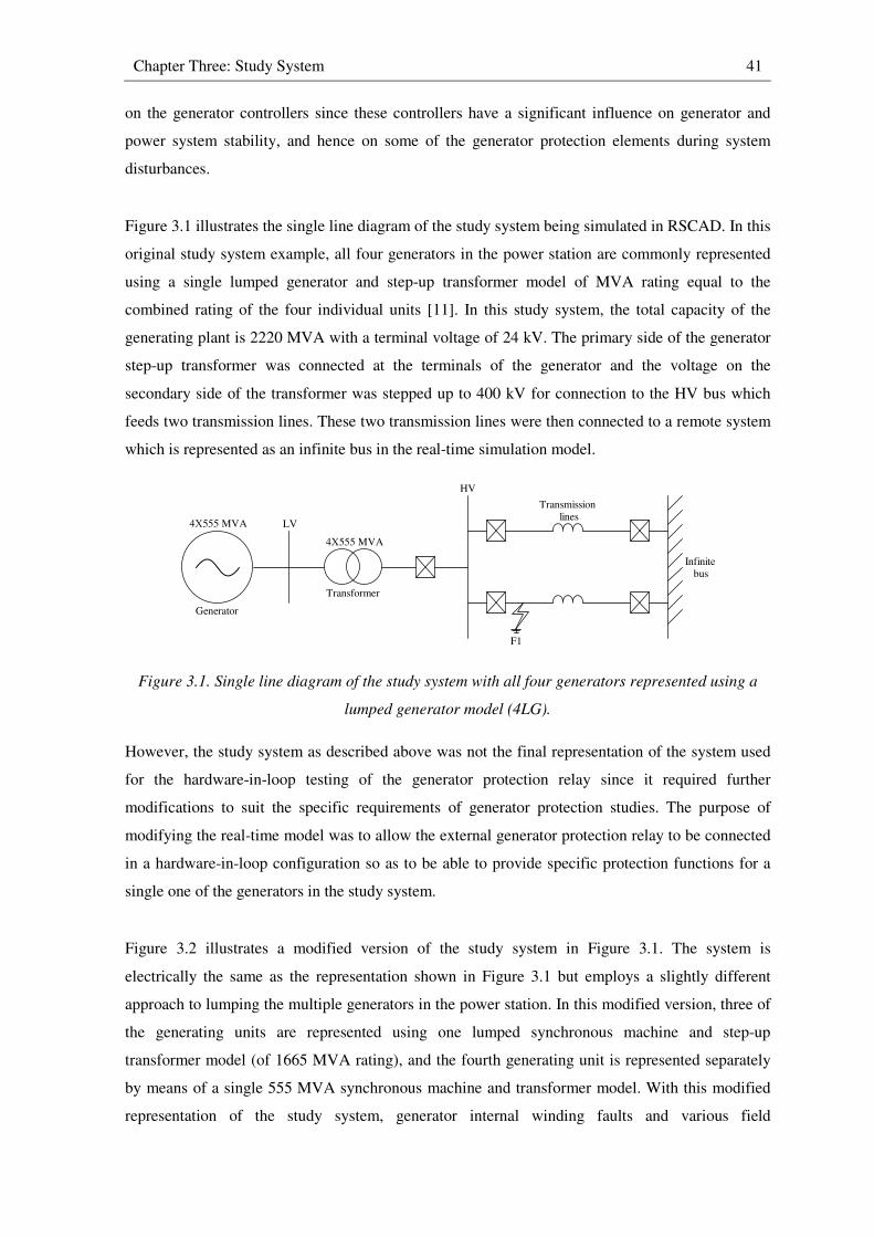
Chapter Three: Study System 41
on the generator controllers since these controllers have a significant influence on generator and
power system stability, and hence on some of the generator protection elements during system
disturbances.
Figure 3.1 illustrates the single line diagram of the study system being simulated in RSCAD. In this
original study system example, all four generators in the power station are commonly represented
using a single lumped generator and step-up transformer model of MVA rating equal to the
combined rating of the four individual units [11]. In this study system, the total capacity of the
generating plant is 2220 MVA with a terminal voltage of 24 kV. The primary side of the generator
step-up transformer was connected at the terminals of the generator and the voltage on the
secondary side of the transformer was stepped up to 400 kV for connection to the HV bus which
feeds two transmission lines. These two transmission lines were then connected to a remote system
which is represented as an infinite bus in the real-time simulation model.
Figure 3.1. Single line diagram of the study system with all four generators represented using a
lumped generator model (4LG).
However, the study system as described above was not the final representation of the system used
for the hardware-in-loop testing of the generator protection relay since it required further
modifications to suit the specific requirements of generator protection studies. The purpose of
modifying the real-time model was to allow the external generator protection relay to be connected
in a hardware-in-loop configuration so as to be able to provide specific protection functions for a
single one of the generators in the study system.
Figure 3.2 illustrates a modified version of the study system in Figure 3.1. The system is
electrically the same as the representation shown in Figure 3.1 but employs a slightly different
approach to lumping the multiple generators in the power station. In this modified version, three of
the generating units are represented using one lumped synchronous machine and step-up
transformer model (of 1665 MVA rating), and the fourth generating unit is represented separately
by means of a single 555 MVA synchronous machine and transformer model. With this modified
representation of the study system, generator internal winding faults and various field
Infinite
bus
Transformer
LV
HV
Generator
Transmission
lines4Χ555 MVA
F1
4Χ555 MVA

Chapter Three: Study System 42
contingencies can be considered on a single generator in the station. This approach not only allows
for more realistic interfacing between the real-time model of the generator and the external relay in
terms of the required current transformer turns ratios, but also, in the case of certain protection
functions such as loss-of-field (40) it is important that the behaviour of the neighbouring, healthy
generators in the station during such an event, and their influence on the response of the faulted
generator and its protection, are represented properly.
Figure 3.2. Single line diagram of the study system with three of the units represented using a
lumped generator model (3LG) and one unit represented using a single generator model (1G).
Figure 3.3. Single line diagram of the study system with two of the units represented using a
lumped generator model (2LG) and two units each represented using a single generator model
(1G).
Infinite bus
Transformer
LV
HV
1Χ555 MVA
Generator
3Χ555 MVA
Transformer
LV
Transmission
lines
F1
1Χ555 MVA
3Χ555 MVA
1Χ555 MVAC
B
A
F2F3
Infinite bus
HV
Generator (1G)
1Χ555 MVA
Transformer
LV
Transmission lines
Generator (2LG)
2Χ555 MVA
Transformer
LV
Generator (1G)
1Χ555 MVA
Transformer
LV
F1
1Χ555 MVA
1Χ555 MVA
2Χ555 MVA
F2

Chapter Three: Study System 43
A generator’s stability can be significantly influenced when a large system disturbance occurs
inside or near the power station. For this reason, out-of-step protection (78) is employed to detect
and isolate unstable generators that cannot return to steady-state operation after a system
disturbance. For the purpose of examining the performance of an out-of-step protection (78)
function that is implemented to protect a particular 555 MVA generator within the power station of
the chosen study system, another modified version of the study system was developed in order to
allow a large system disturbance inside the power station to be represented.
Figure 3.3 illustrates this second modified version of the original study system in Figure 3.1. The
system is again electrically the same as the representation shown in Figure 3.1 but now employs
another approach to lumping the multiple generators in the power station. In this representation,
two of the generating units are represented using one lumped synchronous machine and step up
transformer model (of 1110 MVA rating), while the third and fourth generating units are
represented separately by means of single 555 MVA synchronous machine and transformer models.
Including this level of detail in the model of the study system makes it possible to study the
response of out-of-step protection functions on one generator unit to a severe fault at the terminal
of a single, neighbouring unit in the same station that may, or may not be tripped out as a result of
the contingency and may not have been operating at the same steady-state operating conditions of
active and reactive power output prior to the disturbance.
3.3 Real-time model of study system for low-resistance grounded generator protection studies
As discussed in the previous chapter, there are many grounding schemes available for generators.
This section presents the real-time simulation model of the study system just described which was
developed for the particular requirements of studying the protection of low-resistance grounded
generators in Chapters Four and Five.
Figure 3.4 shows the new phase-domain synchronous machine model available for the real-time
simulator platform in RSCAD. This new model differs from the more regular form of machine
model used on the real-time simulator and in other simulation programmes in many respects. The
major difference is that this new synchronous machine model has the ability to represent realistic
internal winding faults on the stator circuit. This new feature provided by the phase-domain
synchronous machine model allows the user to apply an internal winding fault on the stator
winding at a user-settable location from end of the winding all the way to the generator stator
terminals. The model therefore offers the facility to test the performance of generator winding
protection schemes such as generator differential protection (87P) or (87N), 100% stator ground
fault protection (64G) and neutral injection (64S). Figure 3.4 also illustrates two different modes in
which the phase-domain synchronous machine model can be employed in real-time studies. The
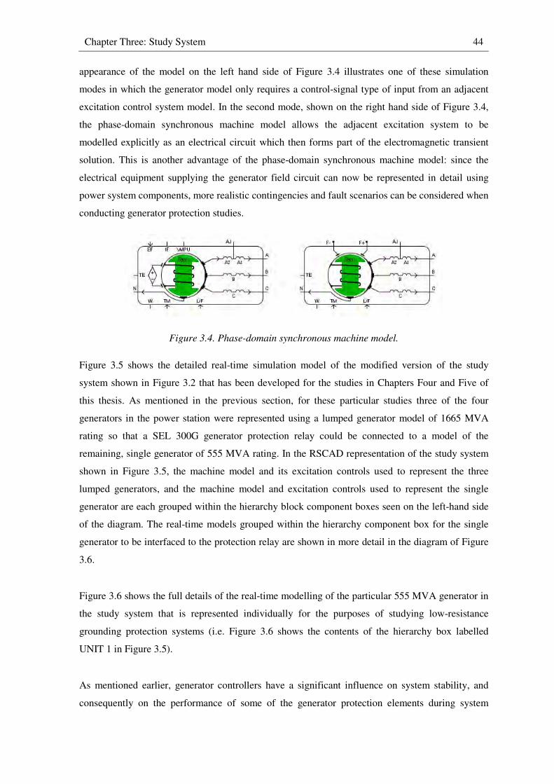
Chapter Three: Study System 44
appearance of the model on the left hand side of Figure 3.4 illustrates one of these simulation
modes in which the generator model only requires a control-signal type of input from an adjacent
excitation control system model. In the second mode, shown on the right hand side of Figure 3.4,
the phase-domain synchronous machine model allows the adjacent excitation system to be
modelled explicitly as an electrical circuit which then forms part of the electromagnetic transient
solution. This is another advantage of the phase-domain synchronous machine model: since the
electrical equipment supplying the generator field circuit can now be represented in detail using
power system components, more realistic contingencies and fault scenarios can be considered when
conducting generator protection studies.
Figure 3.4. Phase-domain synchronous machine model.
Figure 3.5 shows the detailed real-time simulation model of the modified version of the study
system shown in Figure 3.2 that has been developed for the studies in Chapters Four and Five of
this thesis. As mentioned in the previous section, for these particular studies three of the four
generators in the power station were represented using a lumped generator model of 1665 MVA
rating so that a SEL 300G generator protection relay could be connected to a model of the
remaining, single generator of 555 MVA rating. In the RSCAD representation of the study system
shown in Figure 3.5, the machine model and its excitation controls used to represent the three
lumped generators, and the machine model and excitation controls used to represent the single
generator are each grouped within the hierarchy block component boxes seen on the left-hand side
of the diagram. The real-time models grouped within the hierarchy component box for the single
generator to be interfaced to the protection relay are shown in more detail in the diagram of Figure
3.6.
Figure 3.6 shows the full details of the real-time modelling of the particular 555 MVA generator in
the study system that is represented individually for the purposes of studying low-resistance
grounding protection systems (i.e. Figure 3.6 shows the contents of the hierarchy box labelled
UNIT 1 in Figure 3.5).
As mentioned earlier, generator controllers have a significant influence on system stability, and
consequently on the performance of some of the generator protection elements during system
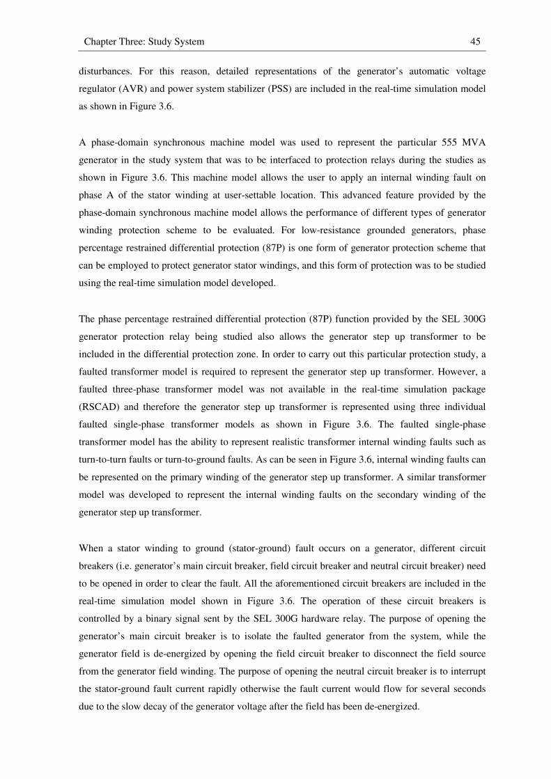
Chapter Three: Study System 45
disturbances. For this reason, detailed representations of the generator’s automatic voltage
regulator (AVR) and power system stabilizer (PSS) are included in the real-time simulation model
as shown in Figure 3.6.
A phase-domain synchronous machine model was used to represent the particular 555 MVA
generator in the study system that was to be interfaced to protection relays during the studies as
shown in Figure 3.6. This machine model allows the user to apply an internal winding fault on
phase A of the stator winding at user-settable location. This advanced feature provided by the
phase-domain synchronous machine model allows the performance of different types of generator
winding protection scheme to be evaluated. For low-resistance grounded generators, phase
percentage restrained differential protection (87P) is one form of generator protection scheme that
can be employed to protect generator stator windings, and this form of protection was to be studied
using the real-time simulation model developed.
The phase percentage restrained differential protection (87P) function provided by the SEL 300G
generator protection relay being studied also allows the generator step up transformer to be
included in the differential protection zone. In order to carry out this particular protection study, a
faulted transformer model is required to represent the generator step up transformer. However, a
faulted three-phase transformer model was not available in the real-time simulation package
(RSCAD) and therefore the generator step up transformer is represented using three individual
faulted single-phase transformer models as shown in Figure 3.6. The faulted single-phase
transformer model has the ability to represent realistic transformer internal winding faults such as
turn-to-turn faults or turn-to-ground faults. As can be seen in Figure 3.6, internal winding faults can
be represented on the primary winding of the generator step up transformer. A similar transformer
model was developed to represent the internal winding faults on the secondary winding of the
generator step up transformer.
When a stator winding to ground (stator-ground) fault occurs on a generator, different circuit
breakers (i.e. generator’s main circuit breaker, field circuit breaker and neutral circuit breaker) need
to be opened in order to clear the fault. All the aforementioned circuit breakers are included in the
real-time simulation model shown in Figure 3.6. The operation of these circuit breakers is
controlled by a binary signal sent by the SEL 300G hardware relay. The purpose of opening the
generator’s main circuit breaker is to isolate the faulted generator from the system, while the
generator field is de-energized by opening the field circuit breaker to disconnect the field source
from the generator field winding. The purpose of opening the neutral circuit breaker is to interrupt
the stator-ground fault current rapidly otherwise the fault current would flow for several seconds
due to the slow decay of the generator voltage after the field has been de-energized.
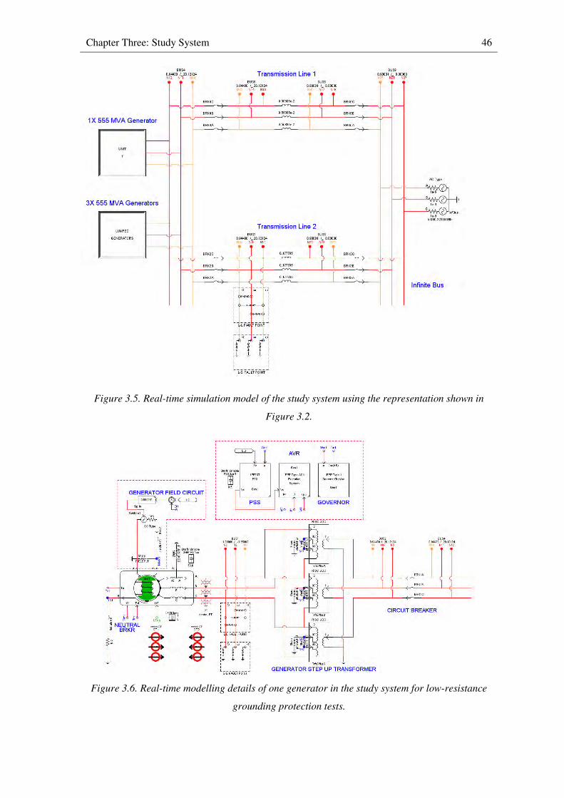
Chapter Three: Study System 46
Figure 3.5. Real-time simulation model of the study system using the representation shown in
Figure 3.2.
Figure 3.6. Real-time modelling details of one generator in the study system for low-resistance
grounding protection tests.
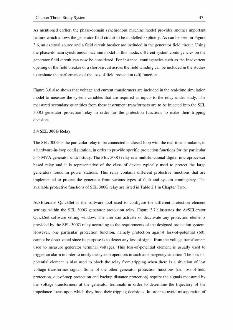
Chapter Three: Study System 47
As mentioned earlier, the phase-domain synchronous machine model provides another important
feature which allows the generator field circuit to be modelled explicitly. As can be seen in Figure
3.6, an external source and a field circuit breaker are included in the generator field circuit. Using
the phase-domain synchronous machine model in this mode, different system contingencies on the
generator field circuit can now be considered. For instance, contingencies such as the inadvertent
opening of the field breaker or a short-circuit across the field winding can be included in the studies
to evaluate the performance of the loss-of-field protection (40) function.
Figure 3.6 also shows that voltage and current transformers are included in the real-time simulation
model to measure the system variables that are required as inputs to the relay under study. The
measured secondary quantities from these instrument transformers are to be injected into the SEL
300G generator protection relay in order for the protection functions to make their tripping
decisions.
3.4 SEL 300G Relay
The SEL 300G is the particular relay to be connected in closed-loop with the real-time simulator, in
a hardware-in-loop configuration, in order to provide specific protection functions for the particular
555 MVA generator under study. The SEL 300G relay is a multifunctional digital microprocessor
based relay and it is representative of the class of device typically used to protect the large
generators found in power stations. This relay contains different protective functions that are
implemented to protect the generator from various types of fault and system contingency. The
available protective functions of SEL 300G relay are listed in Table 2.1 in Chapter Two.
AcSELerator QuickSet is the software tool used to configure the different protection element
settings within the SEL 300G generator protection relay. Figure 3.7 illustrates the AcSELerator
QuickSet software setting window. The user can activate or deactivate any protection elements
provided by the SEL 300G relay according to the requirements of the designed protection system.
However, one particular protection function, namely protection against loss-of-potential (60),
cannot be deactivated since its purpose is to detect any loss of signal from the voltage transformers
used to measure generator terminal voltages. This loss-of-potential element is usually used to
trigger an alarm in order to notify the system operators in such an emergency situation. The loss-of-
potential element is also used to block the relay from tripping when there is a situation of lost
voltage transformer signal. Some of the other generator protection functions (i.e. loss-of-field
protection, out-of-step protection and backup distance protection) require the signals measured by
the voltage transformers at the generator terminals in order to determine the trajectory of the
impedance locus upon which they base their tripping decisions. In order to avoid misoperation of
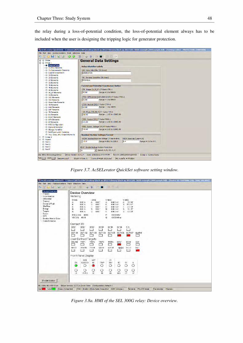
Chapter Three: Study System 48
the relay during a loss-of-potential condition, the loss-of-potential element always has to be
included when the user is designing the tripping logic for generator protection.
Figure 3.7. AcSELerator QuickSet software setting window.
Figure 3.8a. HMI of the SEL 300G relay: Device overview.
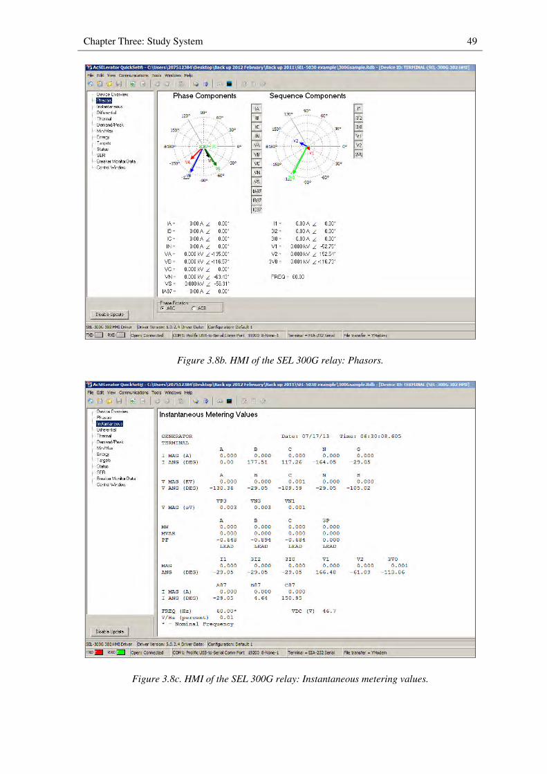
Chapter Three: Study System 49
Figure 3.8b. HMI of the SEL 300G relay: Phasors.
Figure 3.8c. HMI of the SEL 300G relay: Instantaneous metering values.
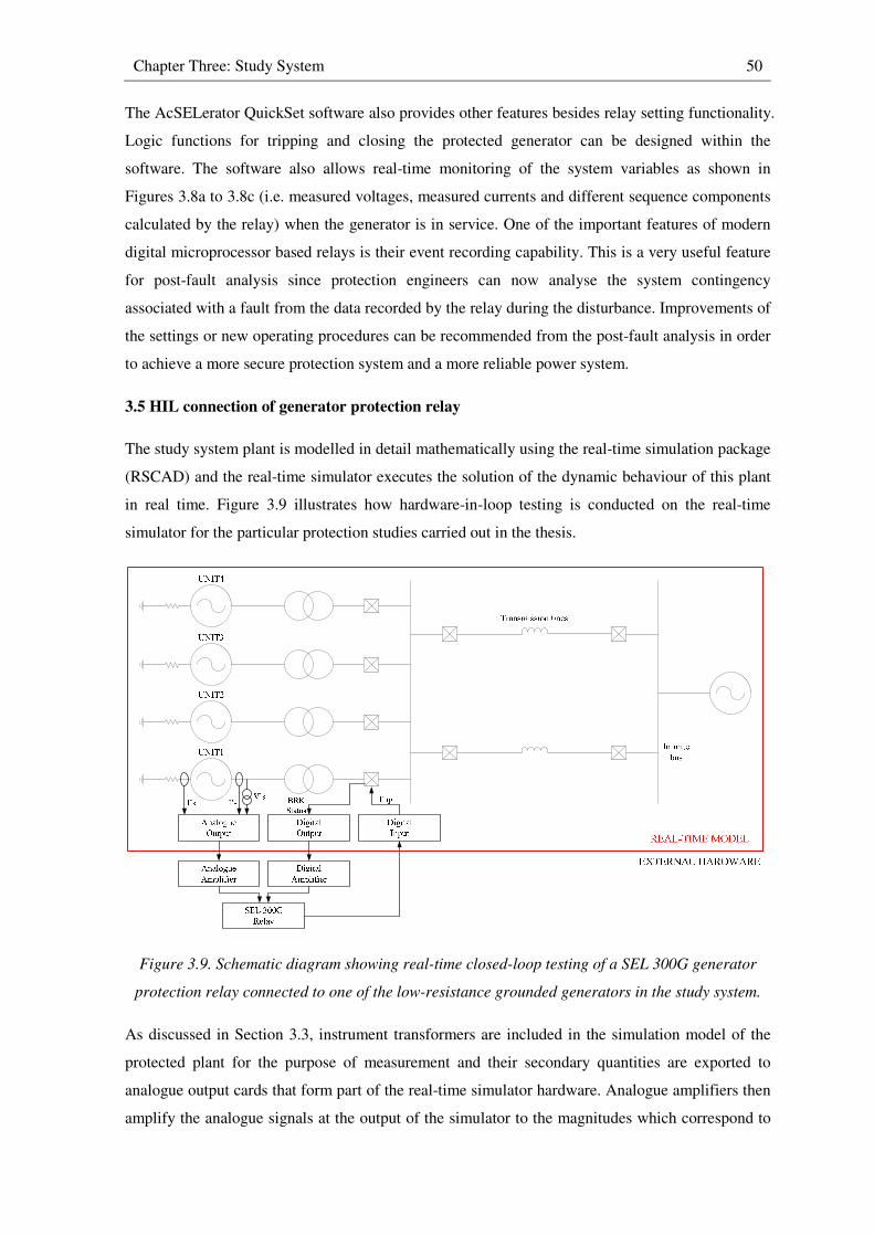
Chapter Three: Study System 50
The AcSELerator QuickSet software also provides other features besides relay setting functionality.
Logic functions for tripping and closing the protected generator can be designed within the
software. The software also allows real-time monitoring of the system variables as shown in
Figures 3.8a to 3.8c (i.e. measured voltages, measured currents and different sequence components
calculated by the relay) when the generator is in service. One of the important features of modern
digital microprocessor based relays is their event recording capability. This is a very useful feature
for post-fault analysis since protection engineers can now analyse the system contingency
associated with a fault from the data recorded by the relay during the disturbance. Improvements of
the settings or new operating procedures can be recommended from the post-fault analysis in order
to achieve a more secure protection system and a more reliable power system.
3.5 HIL connection of generator protection relay
The study system plant is modelled in detail mathematically using the real-time simulation package
(RSCAD) and the real-time simulator executes the solution of the dynamic behaviour of this plant
in real time. Figure 3.9 illustrates how hardware-in-loop testing is conducted on the real-time
simulator for the particular protection studies carried out in the thesis.
Figure 3.9. Schematic diagram showing real-time closed-loop testing of a SEL 300G generator
protection relay connected to one of the low-resistance grounded generators in the study system.
As discussed in Section 3.3, instrument transformers are included in the simulation model of the
protected plant for the purpose of measurement and their secondary quantities are exported to
analogue output cards that form part of the real-time simulator hardware. Analogue amplifiers then
amplify the analogue signals at the output of the simulator to the magnitudes which correspond to
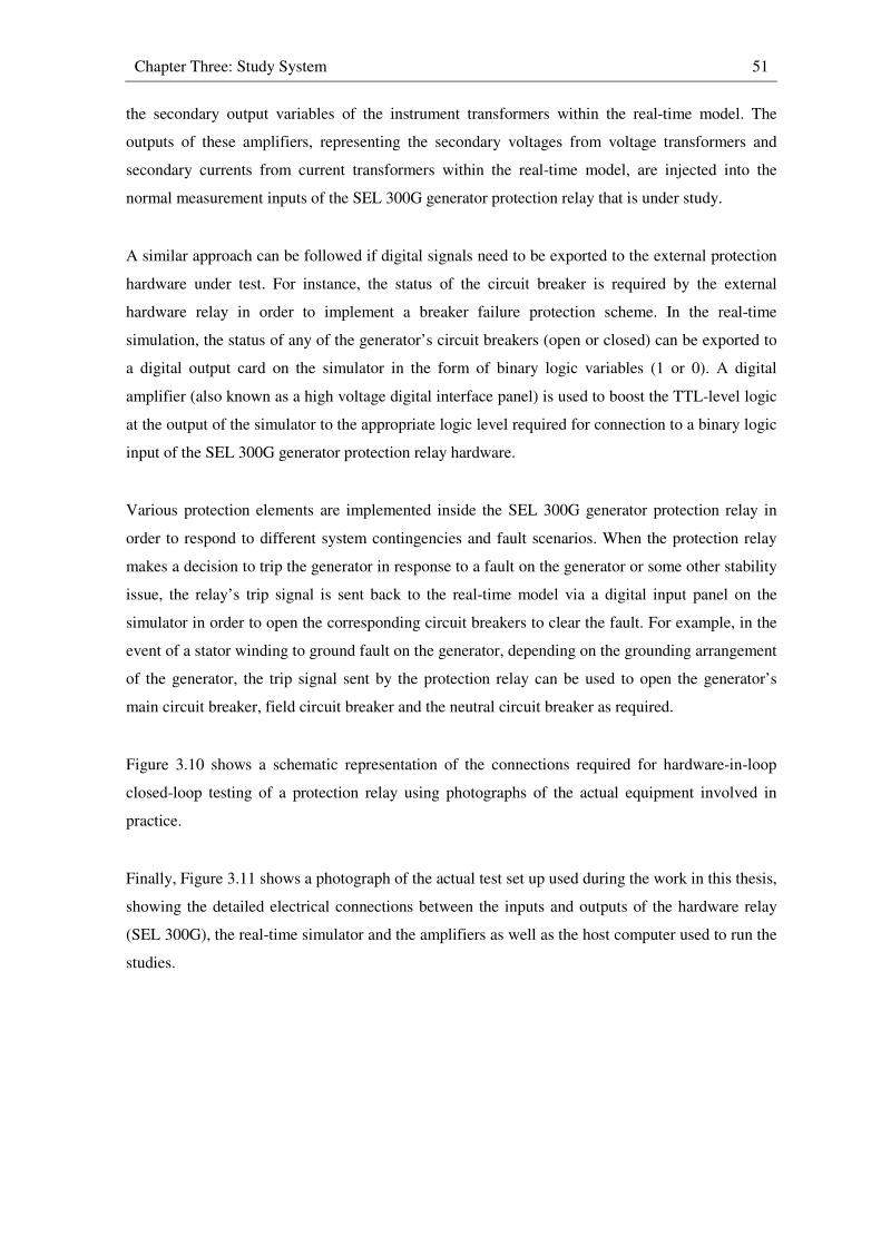
Chapter Three: Study System 51
the secondary output variables of the instrument transformers within the real-time model. The
outputs of these amplifiers, representing the secondary voltages from voltage transformers and
secondary currents from current transformers within the real-time model, are injected into the
normal measurement inputs of the SEL 300G generator protection relay that is under study.
A similar approach can be followed if digital signals need to be exported to the external protection
hardware under test. For instance, the status of the circuit breaker is required by the external
hardware relay in order to implement a breaker failure protection scheme. In the real-time
simulation, the status of any of the generator’s circuit breakers (open or closed) can be exported to
a digital output card on the simulator in the form of binary logic variables (1 or 0). A digital
amplifier (also known as a high voltage digital interface panel) is used to boost the TTL-level logic
at the output of the simulator to the appropriate logic level required for connection to a binary logic
input of the SEL 300G generator protection relay hardware.
Various protection elements are implemented inside the SEL 300G generator protection relay in
order to respond to different system contingencies and fault scenarios. When the protection relay
makes a decision to trip the generator in response to a fault on the generator or some other stability
issue, the relay’s trip signal is sent back to the real-time model via a digital input panel on the
simulator in order to open the corresponding circuit breakers to clear the fault. For example, in the
event of a stator winding to ground fault on the generator, depending on the grounding arrangement
of the generator, the trip signal sent by the protection relay can be used to open the generator’s
main circuit breaker, field circuit breaker and the neutral circuit breaker as required.
Figure 3.10 shows a schematic representation of the connections required for hardware-in-loop
closed-loop testing of a protection relay using photographs of the actual equipment involved in
practice.
Finally, Figure 3.11 shows a photograph of the actual test set up used during the work in this thesis,
showing the detailed electrical connections between the inputs and outputs of the hardware relay
(SEL 300G), the real-time simulator and the amplifiers as well as the host computer used to run the
studies.
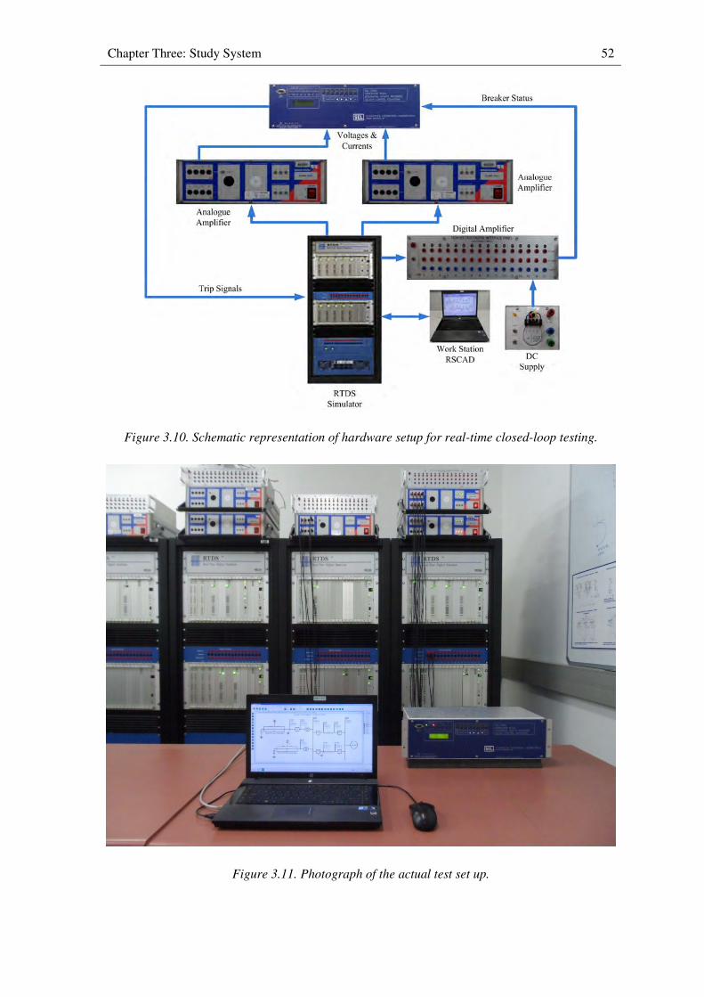
Chapter Three: Study System 52
Figure 3.10. Schematic representation of hardware setup for real-time closed-loop testing.
Figure 3.11. Photograph of the actual test set up.
Chapter Three: Study System 53
3.6 Generic real-time model of generator protection relay
As mentioned in Chapter One, the RSCAD programme provides various pre-developed generic
models of protection relays for real-time simulation studies. There are several advantages to using
these software protection relay models. Firstly, users can familiarise themselves with the protection
philosophies and setting calculations using software relay models. Secondly, various protection
studies can be conducted using these software relay models if hardware relays are not available.
In the studies of loss-of-field protection (40) and out-of-step protection (78), RSCAD’s pre-
developed generic real-time model of a generator protection relay was included in the real-time
simulation model to run in parallel with the hardware generator protection relay (SEL 300G). This
highly-detailed software generator protection relay is a multifunctional relay which possesses
features that are similar to actual generator protection relay hardware. The purpose of using the
software generator protection relay was to gain more insight into the dynamic behaviour of the
actual hardware generator protection relay during particular protection studies rather than to predict
the performance of the actual hardware relay. In other words, the software relay model was only
used to display the trajectory of the positive sequence impedance in the R-X impedance plane
during studies of loss-of-field protection (40) and out-of-step protection (78). The tripping
characteristics of the aforementioned protection functions can then be overlaid onto the recorded
impedance’s trajectory in the R-X impedance plane for explaining the behaviour of the actual
hardware relay during these particular protection studies.
3.7 Conclusion
This chapter has presented an overview of the study system to be used for real-time closed-loop
testing of a SEL 300G generator protection relay. The development of the real-time simulation
model, based on a well-known study system, and the reasons for certain modifications in the
representation of the generators in the system were also discussed in detail.
The functionalities for both the SEL 300G generator protection relay and RSCAD’s software
generator protection relay model were reviewed in order to provide some background to the
equipment under test. Furthermore, the equipment set up used for this particular project was
presented in order to illustrate how real-time closed-loop testing is conducted for the SEL 300G
generator protection relay. This chapter, in short, has presented all the preparation work that was
required before conducting the actual hardware-in-loop tests on the SEL 300G generator protection
relay.
Chapter Three: Study System 54
Chapter Four focuses on the theory behind, and setting calculations for, the particular generator
protective functions that are to be studied in the hardware-in-loop tests to be presented in Chapter
Five, namely phase percentage restrained differential protection (87P), loss-of-field protection (40)
and out-of-step protection (78).

CHAPTER 4
THEORY AND SETTINGS FOR LOW-RESISTANCE GROUNDED
GENERATOR PROTECTION STUDIES
4.1 Introduction
In the previous chapter, the details of the particular study system selected for conducting real-time
closed-loop studies were reviewed. In addition, different real-time simulation models of the
selected study system were introduced to suit the particular requirements when testing a range of
different protection functions available on the SEL 300G relay. The approach used in practice to
interconnect the real-time simulator and the SEL 300G relay hardware was also demonstrated to
provide some background to the work performed in the thesis.
Before evaluating the particular protection functions of interest on the SEL 300G generator
protection relay using the real-time closed-loop testing approach, full settings for these protection
elements have to be configured on the relay. This chapter focuses on the theory of operation and
setting calculations for the particular generator protective functions to be studied in the hardware-
in-loop tests to be presented in Chapter Five, namely phase percentage restrained differential
protection (87P), loss-of-field protection (40) and out-of-step protection (78). In addition, different
practical setting considerations for each of the aforementioned protection elements are discussed in
detail.
4.2 Phase percentage restrained differential protection (87P)
There are different types of fault that can occur on the stator windings of a generator. The main
types of stator winding fault are: phase to earth faults, phase to phase faults, and inter-turn faults
involving turns of the same phase winding. Of these faults, a phase to earth fault is the most
common occurrence on the stator winding [42]. When a phase to earth fault occurs on the stator
winding of a low-resistance grounded generator, it will produce a large fault current that flows in
the stator winding which can cause severe damage to both stator winding and stator core. For this
reason, the generator must be tripped as quickly as possible in order to avoid severe damage during
a stator winding to ground (stator-ground) fault in low-resistance grounded units.
The phase percentage restrained differential protection function (87P) provided by the SEL 300G
relay is one form of protection scheme that can be implemented to protect the stator windings of a
low-resistance grounded generator. This protection scheme relies on measurement of the currents at
both ends of the stator winding of the protected generator in order to calculate differential and
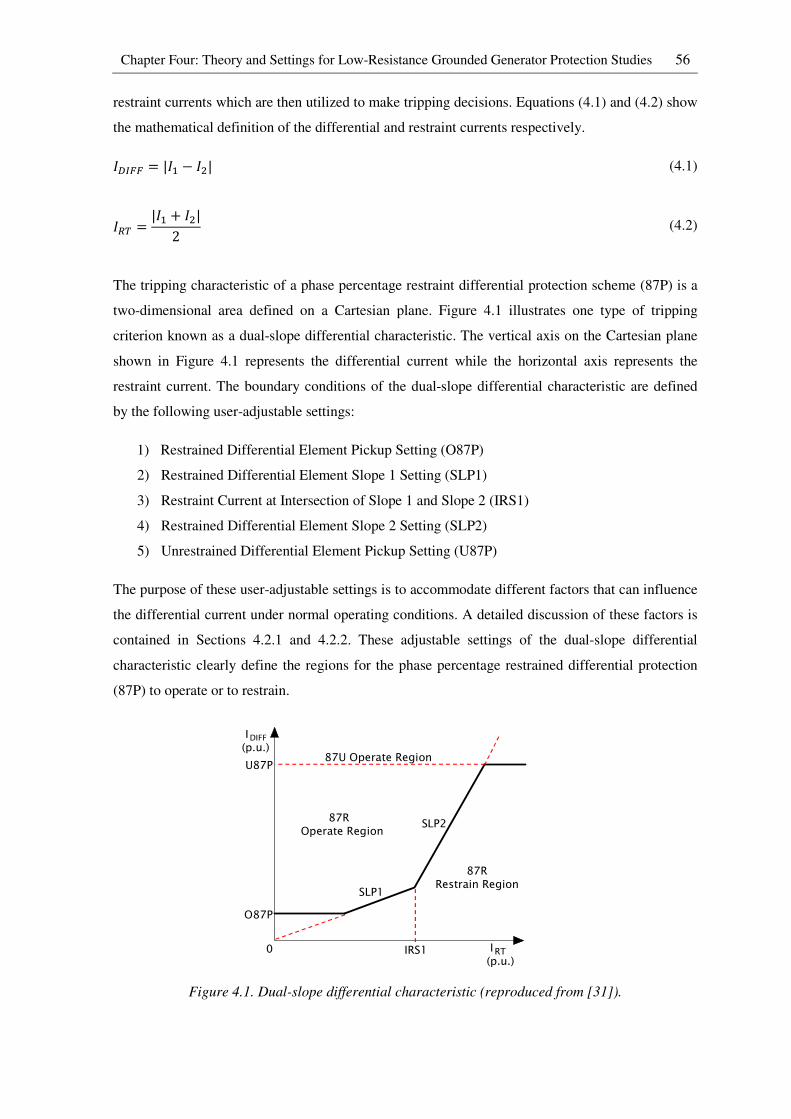
Chapter Four: Theory and Settings for Low-Resistance Grounded Generator Protection Studies 56
restraint currents which are then utilized to make tripping decisions. Equations (4.1) and (4.2) show
the mathematical definition of the differential and restraint currents respectively.
7>?@@ = |74 − 7�| (4.1)
7#B = |74 + 7�|2 (4.2)
The tripping characteristic of a phase percentage restraint differential protection scheme (87P) is a
two-dimensional area defined on a Cartesian plane. Figure 4.1 illustrates one type of tripping
criterion known as a dual-slope differential characteristic. The vertical axis on the Cartesian plane
shown in Figure 4.1 represents the differential current while the horizontal axis represents the
restraint current. The boundary conditions of the dual-slope differential characteristic are defined
by the following user-adjustable settings:
1) Restrained Differential Element Pickup Setting (O87P)
2) Restrained Differential Element Slope 1 Setting (SLP1)
3) Restraint Current at Intersection of Slope 1 and Slope 2 (IRS1)
4) Restrained Differential Element Slope 2 Setting (SLP2)
5) Unrestrained Differential Element Pickup Setting (U87P)
The purpose of these user-adjustable settings is to accommodate different factors that can influence
the differential current under normal operating conditions. A detailed discussion of these factors is
contained in Sections 4.2.1 and 4.2.2. These adjustable settings of the dual-slope differential
characteristic clearly define the regions for the phase percentage restrained differential protection
(87P) to operate or to restrain.
Figure 4.1. Dual-slope differential characteristic (reproduced from [31]).
I(p.u.)
U87P
O87P
87ROperate Region
87RRestrain Region
I(p.u.)
IRS1
SLP1
SLP2
87U Operate Region
0
DIFF
RT

Chapter Four: Theory and Settings for Low-Resistance Grounded Generator Protection Studies 57
The logic diagram shown in Figure 4.2 illustrates the algorithm implemented by the SEL 300G
generator protection relay for the phase percentage differential protection scheme. For the phase
percentage restrained differential protection (87P) to operate, there must be sufficient differential
current to cause the differential versus restraint current trajectory to pass into the tripping area of
the dual-slope differential characteristic.
Figure 4.2. Logic diagram of phase percentage differential protection (reproduced from [31]).
As discussed earlier, phase percentage restrained differential protection (87P) is implemented to
protect the stator windings of a low-resistance grounded generator. However, the SEL 300G relay
also allows the option for the generator step up (GSU) transformer to be included in the differential
protection zone. Sections 4.2.1 and 4.2.2 illustrate different setting calculations and considerations
for each of these different protection arrangement options.
4.2.1 Settings of the 87P element without GSU transformer included
In this section, only the single, 555 MVA, low-resistance grounded generator shown in Figure 3.2
is considered when calculating the settings for the phase percentage restrained differential
protection scheme.
The first step is to calculate the full-load secondary outputs of the current transformers used to
measure the currents in the generator stator windings since this information is required as a relay
input setting. Under healthy generator operating conditions, the full-load stator current of the
protected generator can be calculated as follows.
RelayWord
+-
OperateCurrents
ISettingsU87P
O87P
RestraintCurrents
I
SettingsIRS1
Second-Harmonic BlockingCurrentI1F2
SettingsPCT2=OFF
+-
+-
IRT1SLP1100
IRT1SLP2100
SLP1-SLP2100
IRT1+
+-
+-
1
0
I1F2100PCT2
87U287U3
Bits
87U1
87U
87R1
87BL1
(87U2, 87U3 similar)
(87R2, 87R3 similar)
(87BL2, 87BL3 similar)
op1
RT1
Chapter Four: Theory and Settings for Low-Resistance Grounded Generator Protection Studies 58
C8�;, = 555�*D
*8�;, = 241*
78�;, = C8�;,√3 ∙ *8�;, = 555 ∗ 10F√3 ∙ (24 ∗ 10G) = 13.3511D
The current transformers represented in the real-time simulation model have turns ratio of 30000:1
and therefore the secondary outputs of the current transformers are:
7;,� = 78�;,H�IJ�KL = 13.351 ∗ 10G30000/1 = 0.45D
Restrained Differential Element Slope 1 Setting (SLP1):
As discussed in Section 2.5.3.1 in Chapter Two, there are many factors that can result in a
differential current under un-faulted conditions that is not only non-zero, but that also varies with
operating conditions. The purpose of the SLP1 setting is to increase the differential current required
for tripping in direct proportion to the measured restraint current in order to enhance the security of
the protection scheme during normal operating conditions. The following factors are considered
when calculating the Restrained Differential Element Slope 1 Setting value.
1) Measurement accuracies for the current transformers.
2) Pick-up accuracy for the protection relay.
3) Sufficient operating margin.
Different classes of current transformers have different measurement accuracies and therefore the
measurement accuracy must be obtained from the nameplate of that specific current transformer. In
this case, the current transformer measurement accuracy is assumed to be 10%. The relay pickup
accuracy can be obtained from the instruction manual of the relay. In this case, the relay pickup
accuracy is 5% [31]. An operating margin of 5% is typically provided in order to increase the
security of the differential protection scheme. Based on the information given above, the Slope 1
setting can be calculated as follows.
CM+1 = 10%+ 10%+ 5%+ 5% = 30%
Restrained Differential Element Pickup Setting (O87P):
The restrained differential element pickup setting (O87P) defines the minimum pickup value of the
differential current shown in Figure 4.1. The O87P setting is calculated using the guidance shown
in equation (4.3).
Chapter Four: Theory and Settings for Low-Resistance Grounded Generator Protection Studies 59
O87+ = 0.5 ∗ CM+1 ++Q (4.3)
Where +Q = no-load losses of the transformer at maximum voltage [%]
+Q represents the core loss component of current in the transformer equivalent circuit which is
expressed as a percentage of nominal current. This value will only be included in the O87P setting
calculation when the GSU transformer is included in the differential protection zone [43]. In this
case,+Q is equal to zero.
O87+ = 0.5 ∗ 30100 = 0.15<. R. Restrained Differential Element Slope 2 Setting (SLP2):
The purpose of the SLP2 setting is to increase the security of the differential protection scheme
during heavy through-fault conditions. A heavy through-fault condition can result in severe
saturation of a current transformer. When a current transformer saturates, it can no longer faithfully
reproduce the primary current with a scale factor on the secondary side of the current transformer.
As a result, a very high differential current can be obtained under heavy through-fault conditions.
The SLP2 setting is typically set higher than the SLP1 setting in order to further increase the
differential current required for tripping in direct proportion to the measured restraint current
during heavy through-fault conditions. When phase percentage restrained differential protection
(87P) is configured to protect a generator without including the GSU transformer, the SLP2 setting
is fixed to 100%.
Restraint Current at Intersection of Slope 1 and Slope 2 (IRS1):
When the 87P element is configured to protect a generator without including the GSU transformer,
the turning point between slope 1 and slope 2 defined by the value IRS1 is fixed to 3.0 per unit.
Unrestrained Differential Element Pickup Setting (U87P):
The purpose of the Unrestrained Differential Element Pickup Setting (U87P) is to detect very high
differential current that clearly indicates a fault inside the differential protection zone. The U87P
setting is set to 10 per unit as recommended by the relay manufacturer [31].
Table 4.1 summarizes the settings that were used to configure the SEL 300G generator protection
relay when conducting protection studies of the 87P element in which the GSU transformer was
excluded from the differential protection zone.
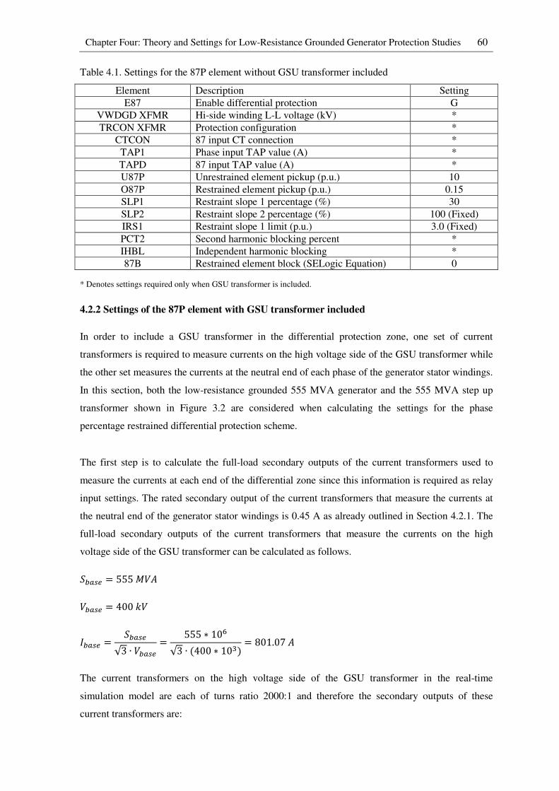
Chapter Four: Theory and Settings for Low-Resistance Grounded Generator Protection Studies 60
Table 4.1. Settings for the 87P element without GSU transformer included
Element Description Setting
E87 Enable differential protection G
VWDGD XFMR Hi-side winding L-L voltage (kV) *
TRCON XFMR Protection configuration *
CTCON 87 input CT connection *
TAP1 Phase input TAP value (A) *
TAPD 87 input TAP value (A) *
U87P Unrestrained element pickup (p.u.) 10
O87P Restrained element pickup (p.u.) 0.15
SLP1 Restraint slope 1 percentage (%) 30
SLP2 Restraint slope 2 percentage (%) 100 (Fixed)
IRS1 Restraint slope 1 limit (p.u.) 3.0 (Fixed)
PCT2 Second harmonic blocking percent *
IHBL Independent harmonic blocking *
87B Restrained element block (SELogic Equation) 0
* Denotes settings required only when GSU transformer is included.
4.2.2 Settings of the 87P element with GSU transformer included
In order to include a GSU transformer in the differential protection zone, one set of current
transformers is required to measure currents on the high voltage side of the GSU transformer while
the other set measures the currents at the neutral end of each phase of the generator stator windings.
In this section, both the low-resistance grounded 555 MVA generator and the 555 MVA step up
transformer shown in Figure 3.2 are considered when calculating the settings for the phase
percentage restrained differential protection scheme.
The first step is to calculate the full-load secondary outputs of the current transformers used to
measure the currents at each end of the differential zone since this information is required as relay
input settings. The rated secondary output of the current transformers that measure the currents at
the neutral end of the generator stator windings is 0.45 A as already outlined in Section 4.2.1. The
full-load secondary outputs of the current transformers that measure the currents on the high
voltage side of the GSU transformer can be calculated as follows.
C8�;, = 555�*D
*8�;, = 4001*
78�;, = C8�;,√3 ∙ *8�;, = 555 ∗ 10F√3 ∙ (400 ∗ 10G) = 801.07D
The current transformers on the high voltage side of the GSU transformer in the real-time
simulation model are each of turns ratio 2000:1 and therefore the secondary outputs of these
current transformers are:
Chapter Four: Theory and Settings for Low-Resistance Grounded Generator Protection Studies 61
7;,� = 78�;,H�IJ�KL = 801.072000/1 = 0.40D
CT ratio mismatch
From the above calculations, one can see that the secondary outputs of the current transformers at
the two ends of the differential protection zone are not exactly the same. Since current transformers
have standard ratios, sometimes it is difficult to select CT ratios that can perfectly match the
currents on the high and low voltage sides of the GSU transformer. This is one of the factors that
results in a non-zero differential current during un-faulted operating conditions.
In modern numerical protection relays, CT ratio mismatch can be compensated for mathematically
by introducing a CT ratio correction factor (also known as an amplitude-matching factor). The
purpose of the CT ratio correction factor is to re-scale input current measurements from different
current transformers in order to minimize the differential current during normal operating
conditions.
In the SEL 300G generator protection relay, the settings TAP1 and TAPD represent the CT ratio
correction factors on the low and high voltage sides of the GSU transformer respectively. The
TAP1 setting is typically set equal to the nominal secondary current of the protected generator [31],
while the TAPD setting can be calculated as follows.
�D+S =*�O� ∙ 7�O� ∙ +�T ∙ H�T ∙ H21000 ∙ *0SUS ∙ H�TS
= 110 ∗ 0.45 ∗ 218 ∗ 30000 ∗ 11000 ∗ 400 ∗ 2000 = 0.40
Where VNOM = generator nominal voltage in secondary volts
INOM = generator nominal current in secondary amps
VWDGD = rated line-to-line voltage on the high voltage side of the transformer in kV
PTR = ratio of the potential transformer at the generator terminal
CTR = ratio of the CT at the neutral end of the generator winding
CTRD = ratio of the CT which is located on the high voltage side of the transformer
C2 = 1.732 if CT configuration = DAB or DAC
C2 = 1 for all other combinations of transformer and CT configuration
Phase shift compensation
In the real-time simulation model shown in Figure 3.6, the GSU transformer is connected in a
delta-star configuration. With this transformer configuration, the measured currents on the low and
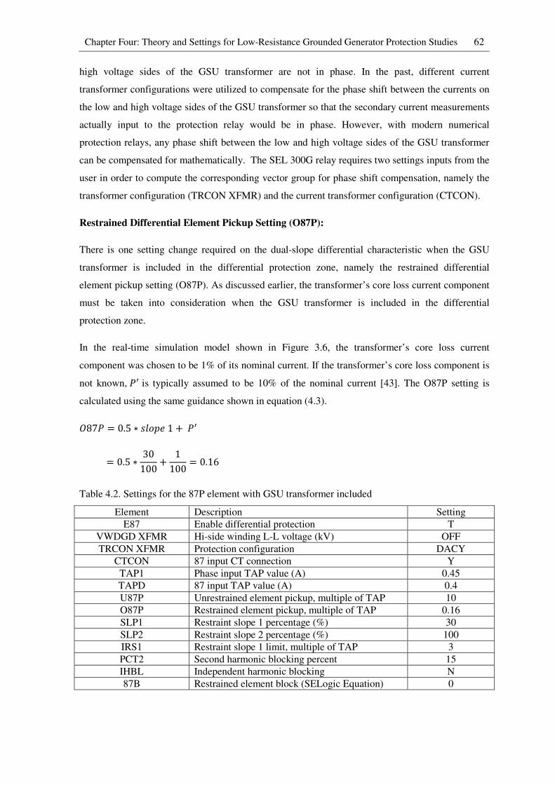
Chapter Four: Theory and Settings for Low-Resistance Grounded Generator Protection Studies 62
high voltage sides of the GSU transformer are not in phase. In the past, different current
transformer configurations were utilized to compensate for the phase shift between the currents on
the low and high voltage sides of the GSU transformer so that the secondary current measurements
actually input to the protection relay would be in phase. However, with modern numerical
protection relays, any phase shift between the low and high voltage sides of the GSU transformer
can be compensated for mathematically. The SEL 300G relay requires two settings inputs from the
user in order to compute the corresponding vector group for phase shift compensation, namely the
transformer configuration (TRCON XFMR) and the current transformer configuration (CTCON).
Restrained Differential Element Pickup Setting (O87P):
There is one setting change required on the dual-slope differential characteristic when the GSU
transformer is included in the differential protection zone, namely the restrained differential
element pickup setting (O87P). As discussed earlier, the transformer’s core loss current component
must be taken into consideration when the GSU transformer is included in the differential
protection zone.
In the real-time simulation model shown in Figure 3.6, the transformer’s core loss current
component was chosen to be 1% of its nominal current. If the transformer’s core loss component is
not known, +Q is typically assumed to be 10% of the nominal current [43]. The O87P setting is
calculated using the same guidance shown in equation (4.3).
O87+ = 0.5 ∗ VWL<�1 ++Q = 0.5 ∗ 30100 + 1100 = 0.16
Table 4.2. Settings for the 87P element with GSU transformer included
Element Description Setting
E87 Enable differential protection T
VWDGD XFMR Hi-side winding L-L voltage (kV) OFF
TRCON XFMR Protection configuration DACY
CTCON 87 input CT connection Y
TAP1 Phase input TAP value (A) 0.45
TAPD 87 input TAP value (A) 0.4
U87P Unrestrained element pickup, multiple of TAP 10
O87P Restrained element pickup, multiple of TAP 0.16
SLP1 Restraint slope 1 percentage (%) 30
SLP2 Restraint slope 2 percentage (%) 100
IRS1 Restraint slope 1 limit, multiple of TAP 3
PCT2 Second harmonic blocking percent 15
IHBL Independent harmonic blocking N
87B Restrained element block (SELogic Equation) 0
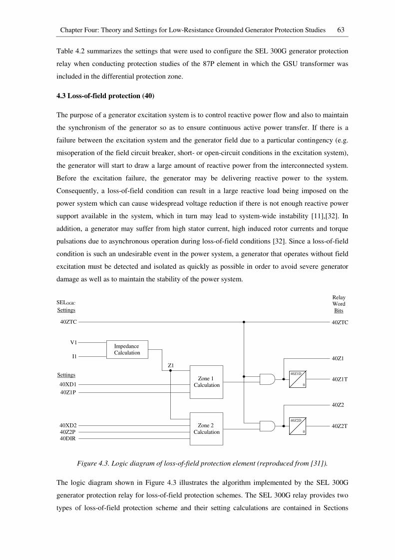
Chapter Four: Theory and Settings for Low-Resistance Grounded Generator Protection Studies 63
Table 4.2 summarizes the settings that were used to configure the SEL 300G generator protection
relay when conducting protection studies of the 87P element in which the GSU transformer was
included in the differential protection zone.
4.3 Loss-of-field protection (40)
The purpose of a generator excitation system is to control reactive power flow and also to maintain
the synchronism of the generator so as to ensure continuous active power transfer. If there is a
failure between the excitation system and the generator field due to a particular contingency (e.g.
misoperation of the field circuit breaker, short- or open-circuit conditions in the excitation system),
the generator will start to draw a large amount of reactive power from the interconnected system.
Before the excitation failure, the generator may be delivering reactive power to the system.
Consequently, a loss-of-field condition can result in a large reactive load being imposed on the
power system which can cause widespread voltage reduction if there is not enough reactive power
support available in the system, which in turn may lead to system-wide instability [11],[32]. In
addition, a generator may suffer from high stator current, high induced rotor currents and torque
pulsations due to asynchronous operation during loss-of-field conditions [32]. Since a loss-of-field
condition is such an undesirable event in the power system, a generator that operates without field
excitation must be detected and isolated as quickly as possible in order to avoid severe generator
damage as well as to maintain the stability of the power system.
Figure 4.3. Logic diagram of loss-of-field protection element (reproduced from [31]).
The logic diagram shown in Figure 4.3 illustrates the algorithm implemented by the SEL 300G
generator protection relay for loss-of-field protection schemes. The SEL 300G relay provides two
types of loss-of-field protection scheme and their setting calculations are contained in Sections
0
40Z1D
0
40Z2D
I1
40ZTC
V1
SELOGIC
Settings
Settings
40XD1
40Z1P
40XD2
40Z2P40DIR
Impedance
Calculation
Z1
Zone 1
Calculation
Zone 2
Calculation
Relay
Word
40ZTC
Bits
40Z1
40Z1T
40Z2
40Z2T

Chapter Four: Theory and Settings for Low-Resistance Grounded Generator Protection Studies 64
4.3.1 and 4.3.2. In both types of loss-of-field protection scheme, two offset-mho elements are
applied at the generator terminals and they are each set to look into the machine. Both types of
protection scheme rely on the measurements taken by the voltage and current transformers at the
generator terminals in order to determine the trajectory of the impedance seen looking back into the
generator, upon which they base their tripping decisions: when excitation on the field of a generator
is lost, the trajectory of this seen impedance will pass into the defined tripping characteristics of the
offset-mho elements on the R-X plane and cause the relay to trip.
It is important to note that the impedance seen by the protection relay has units of ohms in
secondary impedance since the inputs to the relay are the secondary quantities from the voltage and
current transformers at the generator terminals. Therefore the tripping characteristics of loss-of-
field protection schemes are likewise defined in terms of secondary impedance. As such, all
primary impedances must be converted into secondary impedances with consideration for the
current and voltage transformation ratios as shown in equation (4.4).
Y;,�Z��[\ = Y�[]��[\ ∙ H�IJ�KL*�IJ�KL (4.4)
4.3.1 Loss-of-field protection with negative zone 2 offset
Figure 4.4 illustrates one type of loss-of-field protection scheme provided by the SEL 300G relay
that is typically employed to protect generators. This protection scheme contains two offset mho
circles (labelled as zone 1 and zone 2) as shown in Figure 4.4.
Figure 4.4. Operating characteristic of loss-of-field element with negative zone 2 offset
(reproduced from [31]).
Zone1
Zone 2
X
R-X2d'
40Z2P=Xd
40Z1P=1.0pu

Chapter Four: Theory and Settings for Low-Resistance Grounded Generator Protection Studies 65
Before calculating the settings of these tripping characteristics, the base impedance value for the
system must be calculated. The following value of base impedance is calculated from the
generator’s primary quantities using the information presented earlier in Section 4.2.1.
Y8�;,�[]��[\ = *8�;,√3 ∙ 78�;, = 24 ∗ 10G√3 ∗ 13.351 ∗ 10G = 1.0379Ω
As discussed earlier, this primary base impedance must be converted into a secondary base
impedance using equation (4.4). In the real-time simulation model, the voltage transformer ratio is
24000/110 and the current transformer ratio is 30000/1, from which the secondary base impedance
can be calculated as follows.
Y8�;,;,�Z��[\ = Y8�;,�[]��[\ ∙ H�IJ�KL*�IJ�KL
= 1.0379 ∗ 30000/124000/110 = 142.8Ω
Zone 1 setting calculation
The zone 1 mho characteristic is offset from the origin by one half of the value of the generator’s
direct-axis transient reactance (`�Q /2) as shown in Figure 4.4. The purpose of offsetting the mho
characteristic is to avoid misoperation during system disturbances and faults other than loss-of-field
conditions. The diameter of the zone 1 mho circle is typically set to 1 pu. The zone 1 mho element
is typically set to operate without any intentional time delay [31],[32]. If the positive sequence
impedance encroaches the zone 1 mho circle during the worst-case stable generator swing, either
the diameter of the zone 1 mho circle needs to be reduced, or a small time delay needs to be
inserted [31].
�ℎL�KJb���I = 1<R
O((V��I�Jc�J:c� = −`�Q2 = −0.32 = −0.15<R
The above per unit quantities are then converted into ohms using the value of base secondary
impedance (Y8�;,;,�Z��[\) calculated earlier.
�ℎL�KJb���I = 1 ∗ 142.8 = 142.8Ω
O((V��I�Jc�J:c� = −0.15 ∗ 142.83 = −21.4Ω
In the studies considered in this thesis no intentional time delay was set for zone 1.
�Kb���WJd = 0.0V�cL:�

Chapter Four: Theory and Settings for Low-Resistance Grounded Generator Protection Studies 66
Zone 2 setting calculation
The offset of the zone 2 mho characteristic is set to be the same as that for zone 1 as shown in
Figure 4.4. The diameter of the zone 2 mho circle is typically set to the value of the generator’s
direct-axis synchronous (steady-state) reactance(`�). The time delay in this zone is typically set
between 0.5 and 0.6 seconds [31],[32],[34]. The purpose of the time delay inserted in this zone is to
avoid any misoperation of loss-of-field protection for a worst-case stable swing of the generator
caused by contingencies other than a loss-of-field condition, which may also be expected to pass
through the characteristic of this zone.
�ℎL�KJb���I = `� = 1.81<R
O((V��I�Jc�J:c� = −`�Q2 = −0.32 = −0.15<R
The above per unit quantities are then converted into ohms using the value of base secondary
impedance (Y8�;,;,�Z��[\) calculated earlier.
�ℎL�KJb���I = 1.81 ∗ 142.8 = 258.5Ω
O((V��I�Jc�J:c� = −0.15 ∗ 142.8 = −21.4Ω
�Kb���WJd = 0.5V�cL:�
Table 4.3 summarizes the settings that were used to configure the SEL 300G generator protection
relay for real-time closed-loop studies of the aforementioned loss-of-field protection scheme and
the testing results are to be presented in Chapter Five. The results are then utilized to examine the
dynamic performance of such protection schemes under different field contingencies.
Table 4.3. Settings of loss-of-field protection scheme (Negative offset zone 2)
Element Description Setting
E40 Enable loss-of-field protection Y
Zone 1 settings
40Z1P Zone 1 mho diameter (ohms) 142.8
40XD1 Zone 1 offset reactance (ohms) -21.4
40Z1D Zone 1 pickup time delay (seconds) 0.0
Zone 2 settings
40Z2P Zone 2 mho diameter (ohms) 258.5
40XD2 Zone 2 offset reactance (ohms) -21.4
40Z2D Zone 2 pickup time delay (seconds) 0.5
40DIR Zone 2 directional Supervising Angle (degree) *
40ZTC 40Z element torque control (SELogic Equation) !60LOP
* Denotes setting required only when the other type of loss-of-field protection scheme in the SEL 300G relay is
employed.
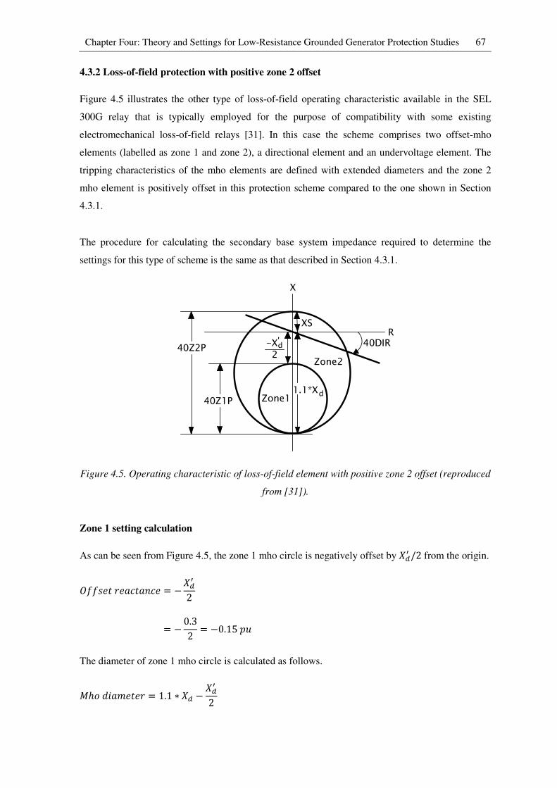
Chapter Four: Theory and Settings for Low-Resistance Grounded Generator Protection Studies 67
4.3.2 Loss-of-field protection with positive zone 2 offset
Figure 4.5 illustrates the other type of loss-of-field operating characteristic available in the SEL
300G relay that is typically employed for the purpose of compatibility with some existing
electromechanical loss-of-field relays [31]. In this case the scheme comprises two offset-mho
elements (labelled as zone 1 and zone 2), a directional element and an undervoltage element. The
tripping characteristics of the mho elements are defined with extended diameters and the zone 2
mho element is positively offset in this protection scheme compared to the one shown in Section
4.3.1.
The procedure for calculating the secondary base system impedance required to determine the
settings for this type of scheme is the same as that described in Section 4.3.1.
Figure 4.5. Operating characteristic of loss-of-field element with positive zone 2 offset (reproduced
from [31]).
Zone 1 setting calculation
As can be seen from Figure 4.5, the zone 1 mho circle is negatively offset by `�Q /2 from the origin.
O((V��I�Jc�J:c� = −`�Q2
= − 0.32 = −0.15<R
The diameter of zone 1 mho circle is calculated as follows.
�ℎL�KJb���I = 1.1 ∗ `� − `�Q2
Zone1
Zone2
X
R-X2d'
40Z2P
40Z1P
XS
40DIR
1.1*Xd

Chapter Four: Theory and Settings for Low-Resistance Grounded Generator Protection Studies 68
= 1.1 ∗ 1.81 − 0.32 = 1.841<R
The above per unit quantities are then converted into ohms using the value of base secondary
impedance (Y8�;,;,�Z��[\) calculated in Section 4.3.1.
O((V��I�Jc�J:c� = −0.15 ∗ 142.8 = −21.4Ω
�ℎL�KJb���I = 1.841 ∗ 142.8 = 262.9Ω
Since the diameter of the zone 1 mho circle is larger in this type of loss-of-field scheme, the
possibility of the generator’s positive sequence impedance encroaching into zone 1 during power
swings or out-of step conditions is increased. Therefore a small time delay is typically inserted in
this zone in order to avoid misoperation during power swings or out-of-step conditions.
�Kb���WJd = 0.25V�cL:�
Zone 2 setting calculation
The offset of the zone 2 mho circle is set to `C as shown in Figure 4.5. `Crepresents the sum of
the GSU transformer impedance (`6[�Z;e[�,[) and the total system impedance (`;\;6,�). For the
study system considered in this thesis, the total system impedance (`;\;6,�) beyond the generator
step up transformer is calculated as follows.
`;\;6,� = 0.5//0.93 = 0.325<R
`C = `6[�Z;e[�,[ + `;\;6,�
= 0.15 + 0.325 = 0.475<R
O((V��I�Jc�J:c� = `C = 0.475<R
The diameter of the zone 2 mho circle is calculated as follows.
�ℎL�KJb���I = 1.1 ∗ `� + `C
= 1.1 ∗ 1.81 + 0.475 = 2.466<R
The above per unit quantities are then converted into ohms using the value of base secondary
impedance (Y8�;,;,�Z��[\) calculated in Section 4.3.1.
O((V��I�Jc�J:c� = 0.475 ∗ 142.8 = 67.8Ω
�ℎL�KJb���I = 2.466 ∗ 142.8 = 352.2Ω
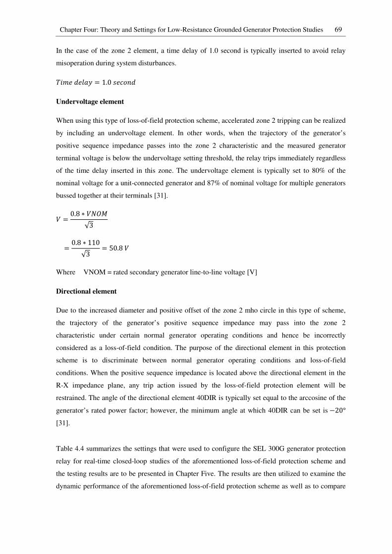
Chapter Four: Theory and Settings for Low-Resistance Grounded Generator Protection Studies 69
In the case of the zone 2 element, a time delay of 1.0 second is typically inserted to avoid relay
misoperation during system disturbances.
�Kb���WJd = 1.0V�cL:�
Undervoltage element
When using this type of loss-of-field protection scheme, accelerated zone 2 tripping can be realized
by including an undervoltage element. In other words, when the trajectory of the generator’s
positive sequence impedance passes into the zone 2 characteristic and the measured generator
terminal voltage is below the undervoltage setting threshold, the relay trips immediately regardless
of the time delay inserted in this zone. The undervoltage element is typically set to 80% of the
nominal voltage for a unit-connected generator and 87% of nominal voltage for multiple generators
bussed together at their terminals [31].
* = 0.8 ∗ *�O�√3
= 0.8 ∗ 110√3 = 50.8*
Where VNOM = rated secondary generator line-to-line voltage [V]
Directional element
Due to the increased diameter and positive offset of the zone 2 mho circle in this type of scheme,
the trajectory of the generator’s positive sequence impedance may pass into the zone 2
characteristic under certain normal generator operating conditions and hence be incorrectly
considered as a loss-of-field condition. The purpose of the directional element in this protection
scheme is to discriminate between normal generator operating conditions and loss-of-field
conditions. When the positive sequence impedance is located above the directional element in the
R-X impedance plane, any trip action issued by the loss-of-field protection element will be
restrained. The angle of the directional element 40DIR is typically set equal to the arccosine of the
generator’s rated power factor; however, the minimum angle at which 40DIR can be set is−20° [31].
Table 4.4 summarizes the settings that were used to configure the SEL 300G generator protection
relay for real-time closed-loop studies of the aforementioned loss-of-field protection scheme and
the testing results are to be presented in Chapter Five. The results are then utilized to examine the
dynamic performance of the aforementioned loss-of-field protection scheme as well as to compare

Chapter Four: Theory and Settings for Low-Resistance Grounded Generator Protection Studies 70
it with the performance of the loss-of-field protection scheme discussed in Section 4.3.1 under the
same types of field contingencies.
Table 4.4. Settings for loss-of-field protection (Positive offset zone 2)
Element Description Setting
E40 Enable loss-of-field protection Y
Zone 1 settings
40Z1P Zone 1 mho diameter (ohms) 262.9
40XD1 Zone 1 offset reactance (ohms) -21.4
40Z1D Zone 1 pickup time delay (seconds) 0.25
Zone 2 settings
40Z2P Zone 2 mho diameter (ohms) 352.2
40XD2 Zone 2 offset reactance (ohms) 67.8
40Z2D Zone 2 pickup time delay (seconds) 1
40DIR Zone 2 directional Supervising Angle (degree) -20
40ZTC 40Z element torque control (SELogic Equation) !60LOP
In both loss-of-field protection schemes discussed in Sections 4.3.1 and 4.3.2, misoperation due to
a loss-of-potential condition (i.e. signals lost from the voltage transformer at the generator
terminals) can be avoided by setting the logic 40ZTC to (!60LOP) as shown in Table 4.3. This
allows the relay to block the trip signal issued by the loss-of-field element during a loss-of-
potential condition.
4.4 Generator out-of-step protection (78)
When an out-of-step condition occurs between two interconnected systems due to transient
disturbances, these systems must be separated as quickly as possible in order to avoid severe
generator damage and adverse cascading tripping effects which may lead to system wide instability.
In the past, the electrical centre during an out-of-step condition was usually out in the transmission
system. However, as a result of significant changes in system and generator impedance
characteristics over the years, the electrical centre can appear in a generator or a generator step up
transformer during an out-of step condition. For this reason, a separate out-of-step protection
function may be employed at the generator terminals to detect out-of-step conditions in which the
electrical centres of the electromechanical swings are close to generator zone.
4.4.1 Generator swing characteristics
Figure 4.6 shows an illustration of a simple power system network and its equivalent circuit
diagram in order to demonstrate the typical behaviour of a system during out-of-step conditions,
and how such conditions can be detected from the variations that take place in the apparent
impedance measured by a relay at the terminal of a generator.
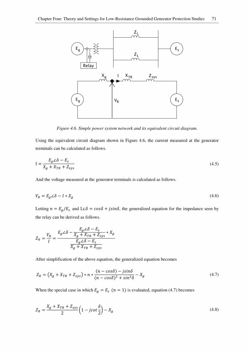
Chapter Four: Theory and Settings for Low-Resistance Grounded Generator Protection Studies 71
Figure 4.6. Simple power system network and its equivalent circuit diagram.
Using the equivalent circuit diagram shown in Figure 4.6, the current measured at the generator
terminals can be calculated as follows.
I = "g∠h − ";g̀ + `B# + Y;\; (4.5)
And the voltage measured at the generator terminals is calculated as follows.
*# = "g∠h − 7 ∗ g̀ (4.6)
Letting : = "g/";and1∠h = cLVh + iVK:h, the generalized equation for the impedance seen by
the relay can be derived as follows.
Y# = *#7 = "g∠h − "g∠h − ";g̀ + `B# + Y;\; ∗ g̀"g∠h − ";g̀ + `B# + Y;\;
After simplification of the above equation, the generalized equation becomes
Y# = j g̀ + `B# + Y;\;k ∗ : ∗ (: − cLVh) − iVK:h(: − cLVh)� + VK:�h − g̀ (4.7)
When the special case in which"g = ";(: = 1) is evaluated, equation (4.7) becomes
Y# = g̀ + `B# + Y;\;2 l1 − icL� h2m − g̀ (4.8)
Relay
Z
E Eg s
L
ZL
Eg Es
Xg
VR
XTR ZsysI
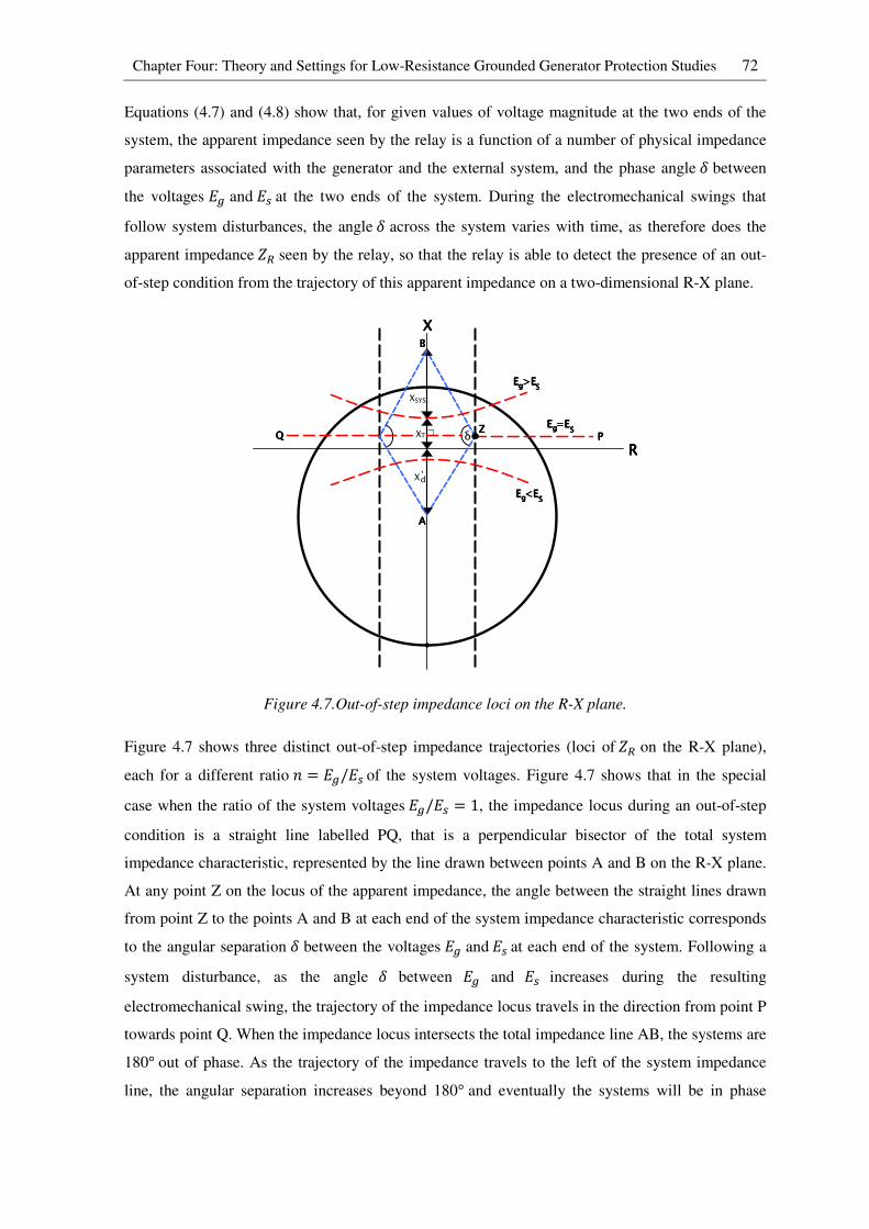
Chapter Four: Theory and Settings for Low-Resistance Grounded Generator Protection Studies 72
Equations (4.7) and (4.8) show that, for given values of voltage magnitude at the two ends of the
system, the apparent impedance seen by the relay is a function of a number of physical impedance
parameters associated with the generator and the external system, and the phase angleh between
the voltages "g and";at the two ends of the system. During the electromechanical swings that
follow system disturbances, the angleh across the system varies with time, as therefore does the
apparent impedanceY#seen by the relay, so that the relay is able to detect the presence of an out-
of-step condition from the trajectory of this apparent impedance on a two-dimensional R-X plane.
Figure 4.7.Out-of-step impedance loci on the R-X plane.
Figure 4.7 shows three distinct out-of-step impedance trajectories (loci ofY# on the R-X plane),
each for a different ratio : = "g/";of the system voltages. Figure 4.7 shows that in the special
case when the ratio of the system voltages"g/"; = 1, the impedance locus during an out-of-step
condition is a straight line labelled PQ, that is a perpendicular bisector of the total system
impedance characteristic, represented by the line drawn between points A and B on the R-X plane.
At any point Z on the locus of the apparent impedance, the angle between the straight lines drawn
from point Z to the points A and B at each end of the system impedance characteristic corresponds
to the angular separation h between the voltages "g and";at each end of the system. Following a
system disturbance, as the angle h between "g and "; increases during the resulting
electromechanical swing, the trajectory of the impedance locus travels in the direction from point P
towards point Q. When the impedance locus intersects the total impedance line AB, the systems are
180° out of phase. As the trajectory of the impedance travels to the left of the system impedance
line, the angular separation increases beyond 180° and eventually the systems will be in phase
RRRR
XXXX
Xd'
XT
XSYS
δ PPPPQQQQE =EE =EE =EE =Egggg SSSS
E >EE >EE >EE >Egggg SSSS
E <EE <EE <EE <Egggg SSSS
AAAA
BBBB
ZZZZ
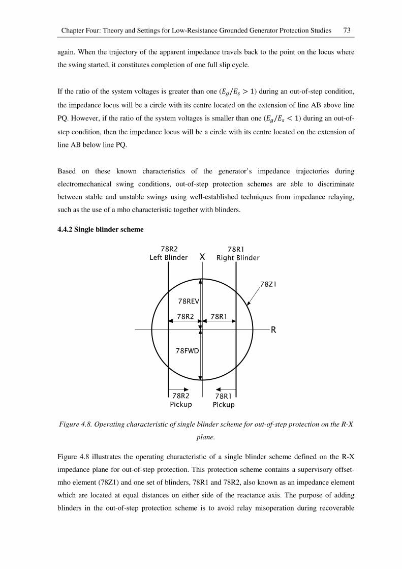
Chapter Four: Theory and Settings for Low-Resistance Grounded Generator Protection Studies 73
again. When the trajectory of the apparent impedance travels back to the point on the locus where
the swing started, it constitutes completion of one full slip cycle.
If the ratio of the system voltages is greater than one ("g/"; > 1) during an out-of-step condition,
the impedance locus will be a circle with its centre located on the extension of line AB above line
PQ. However, if the ratio of the system voltages is smaller than one ("g/"; < 1) during an out-of-
step condition, then the impedance locus will be a circle with its centre located on the extension of
line AB below line PQ.
Based on these known characteristics of the generator’s impedance trajectories during
electromechanical swing conditions, out-of-step protection schemes are able to discriminate
between stable and unstable swings using well-established techniques from impedance relaying,
such as the use of a mho characteristic together with blinders.
4.4.2 Single blinder scheme
Figure 4.8. Operating characteristic of single blinder scheme for out-of-step protection on the R-X
plane.
Figure 4.8 illustrates the operating characteristic of a single blinder scheme defined on the R-X
impedance plane for out-of-step protection. This protection scheme contains a supervisory offset-
mho element (78Z1) and one set of blinders, 78R1 and 78R2, also known as an impedance element
which are located at equal distances on either side of the reactance axis. The purpose of adding
blinders in the out-of-step protection scheme is to avoid relay misoperation during recoverable
78R2 78R1
78REV
78FWD
X
R
78R2Left Blinder
78R1Right Blinder
78R2Pickup
78R1Pickup
78Z1
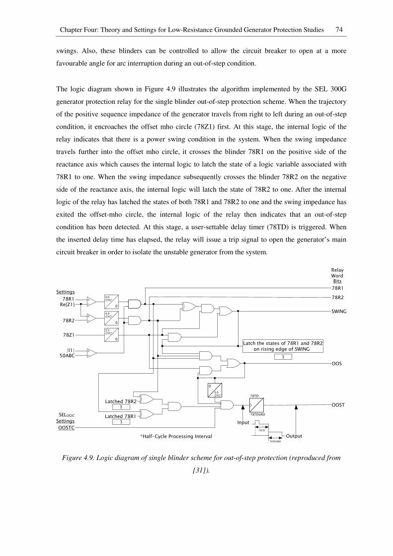
Chapter Four: Theory and Settings for Low-Resistance Grounded Generator Protection Studies 74
swings. Also, these blinders can be controlled to allow the circuit breaker to open at a more
favourable angle for arc interruption during an out-of-step condition.
The logic diagram shown in Figure 4.9 illustrates the algorithm implemented by the SEL 300G
generator protection relay for the single blinder out-of-step protection scheme. When the trajectory
of the positive sequence impedance of the generator travels from right to left during an out-of-step
condition, it encroaches the offset mho circle (78Z1) first. At this stage, the internal logic of the
relay indicates that there is a power swing condition in the system. When the swing impedance
travels further into the offset mho circle, it crosses the blinder 78R1 on the positive side of the
reactance axis which causes the internal logic to latch the state of a logic variable associated with
78R1 to one. When the swing impedance subsequently crosses the blinder 78R2 on the negative
side of the reactance axis, the internal logic will latch the state of 78R2 to one. After the internal
logic of the relay has latched the states of both 78R1 and 78R2 to one and the swing impedance has
exited the offset-mho circle, the internal logic of the relay then indicates that an out-of-step
condition has been detected. At this stage, a user-settable delay timer (78TD) is triggered. When
the inserted delay time has elapsed, the relay will issue a trip signal to open the generator’s main
circuit breaker in order to isolate the unstable generator from the system.
Figure 4.9. Logic diagram of single blinder scheme for out-of-step protection (reproduced from
[31]).
+-
Settings
Relay Word
78R1Re{Z1}
78R2+-
0.5CYC*
0
0.5CYC*
0
0.5CYC*
078Z1
+-
|I1|50ABC
78R1
78R2
SWING
Latch the states of 78R1 and 78R2 on rising edge of SWING
1
OOS
0.5CYC*
0
Latched 78R2
Latched 78R1SELOGICSettings
OOSTC
78TD
78TDURD
Bits
1
1
OOST
*Half-Cycle Processing Interval
Input
Output78TDURD
78TD

Chapter Four: Theory and Settings for Low-Resistance Grounded Generator Protection Studies 75
It is important to note that an unstable generator does not need to be shut down completely. In other
words, only the generator’s main circuit breaker is required to be opened during an out-of-step
condition. When the system stabilizes, the generator can then be resynchronized and connected
back on to the grid without requiring a long start up process.
Single blinder scheme setting calculations
The forward reach 78FWD of the 78Z1 element shown in Figure 4.8 is typically set at 2.0 to 3.0
times the value of the generator’s direct-axis transient reactance`�Q .
78p0S = 3 ∗ `�Q
= 3 ∗ 0.3 = 0.9<R
The reverse reach 78REV of the 78Z1 element shown in Figure 4.8 is typically set at 1.5 to 2.0
times the transformer reactance `6[�Z;e[�,[in order for the element to have an adequate coverage
plus some margin.
78T"* = 2 ∗ `6[�Z;e[�,[
= 2 ∗ 0.15 = 0.3<R
The above per unit quantities are then converted into ohms using the value of base secondary
impedance (Y8�;,;,�Z��[\) calculated in Section 4.3.1.
pLIqJI�I�Jcℎ = 0.9 ∗ 142.8 = 128.5Ω
T�r�IV�I�Jcℎ = 0.3 ∗ 142.8 = 42.8Ω
In order to calculate the blinder setting of this type of out-of-step protection scheme, transient
studies are typically carried out to investigate the maximum angular separation between systems
that may occur without loss of synchronism. Based on the experience described in [11], the
maximum angular separation between a generator and a system that may occur without loss of
synchronism ish��� = 120°. Based on the assumption of h = 120° being the largest possible
angle before the generator pole-slips, the horizontal distance of the blinder from the origin to the
particular point on the impedance locus that corresponds to the angle h = 120° can be calculated
by drawing two straight lines from point Z to the points A and B at each end of the system
impedance characteristic as shown in Figure 4.7.
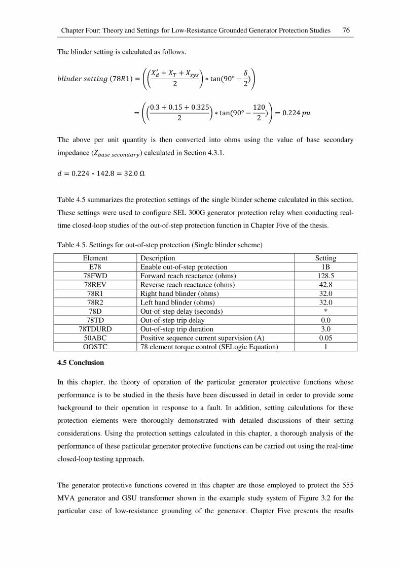
Chapter Four: Theory and Settings for Low-Resistance Grounded Generator Protection Studies 76
The blinder setting is calculated as follows.
sWK:��IV���K:2(78T1) = tu`�Q + `B + `;\;2 v ∗ tan(90° − h2)z
= tl0.3 + 0.15 + 0.3252 m ∗ tan(90° − 1202 )z = 0.224<R
The above per unit quantity is then converted into ohms using the value of base secondary
impedance (Y8�;,;,�Z��[\) calculated in Section 4.3.1.
� = 0.224 ∗ 142.8 = 32.0Ω
Table 4.5 summarizes the protection settings of the single blinder scheme calculated in this section.
These settings were used to configure SEL 300G generator protection relay when conducting real-
time closed-loop studies of the out-of-step protection function in Chapter Five of the thesis.
Table 4.5. Settings for out-of-step protection (Single blinder scheme)
Element Description Setting
E78 Enable out-of-step protection 1B
78FWD Forward reach reactance (ohms) 128.5
78REV Reverse reach reactance (ohms) 42.8
78R1 Right hand blinder (ohms) 32.0
78R2 Left hand blinder (ohms) 32.0
78D Out-of-step delay (seconds) *
78TD Out-of-step trip delay 0.0
78TDURD Out-of-step trip duration 3.0
50ABC Positive sequence current supervision (A) 0.05
OOSTC 78 element torque control (SELogic Equation) 1
4.5 Conclusion
In this chapter, the theory of operation of the particular generator protective functions whose
performance is to be studied in the thesis have been discussed in detail in order to provide some
background to their operation in response to a fault. In addition, setting calculations for these
protection elements were thoroughly demonstrated with detailed discussions of their setting
considerations. Using the protection settings calculated in this chapter, a thorough analysis of the
performance of these particular generator protective functions can be carried out using the real-time
closed-loop testing approach.
The generator protective functions covered in this chapter are those employed to protect the 555
MVA generator and GSU transformer shown in the example study system of Figure 3.2 for the
particular case of low-resistance grounding of the generator. Chapter Five presents the results
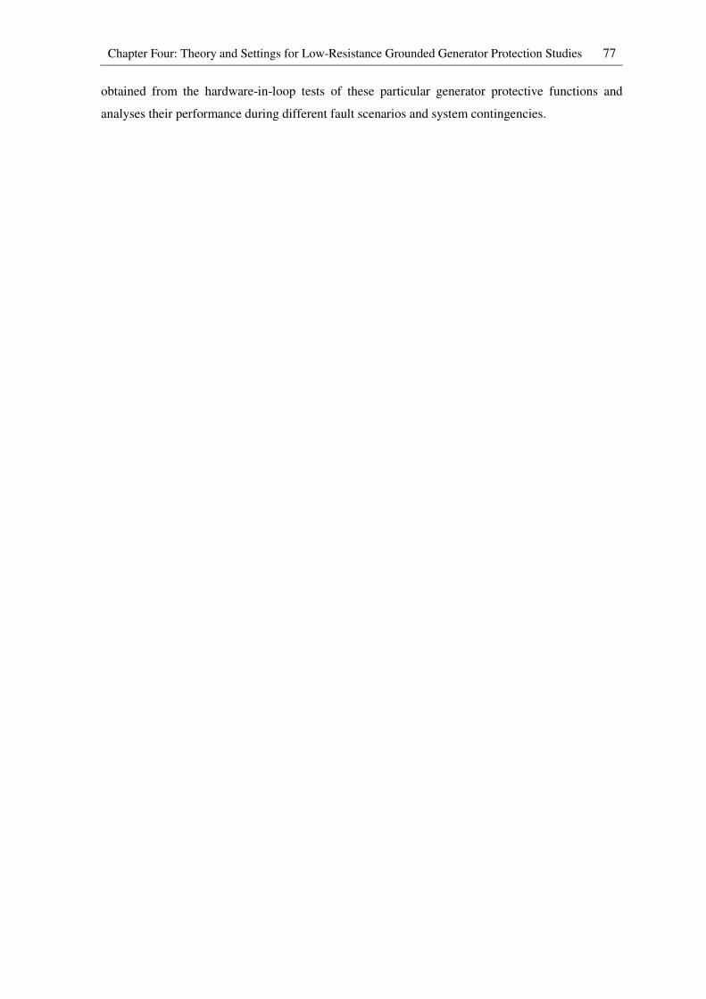
Chapter Four: Theory and Settings for Low-Resistance Grounded Generator Protection Studies 77
obtained from the hardware-in-loop tests of these particular generator protective functions and
analyses their performance during different fault scenarios and system contingencies.
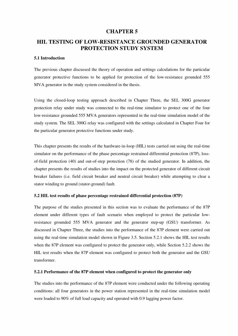
CHAPTER 5
HIL TESTING OF LOW-RESISTANCE GROUNDED GENERATOR
PROTECTION STUDY SYSTEM
5.1 Introduction
The previous chapter discussed the theory of operation and settings calculations for the particular
generator protective functions to be applied for protection of the low-resistance grounded 555
MVA generator in the study system considered in the thesis.
Using the closed-loop testing approach described in Chapter Three, the SEL 300G generator
protection relay under study was connected to the real-time simulator to protect one of the four
low-resistance grounded 555 MVA generators represented in the real-time simulation model of the
study system. The SEL 300G relay was configured with the settings calculated in Chapter Four for
the particular generator protective functions under study.
This chapter presents the results of the hardware-in-loop (HIL) tests carried out using the real-time
simulator on the performance of the phase percentage restrained differential protection (87P), loss-
of-field protection (40) and out-of-step protection (78) of the studied generator. In addition, the
chapter presents the results of studies into the impact on the protected generator of different circuit
breaker failures (i.e. field circuit breaker and neutral circuit breaker) while attempting to clear a
stator winding to ground (stator-ground) fault.
5.2 HIL test results of phase percentage restrained differential protection (87P)
The purpose of the studies presented in this section was to evaluate the performance of the 87P
element under different types of fault scenario when employed to protect the particular low-
resistance grounded 555 MVA generator and the generator step-up (GSU) transformer. As
discussed in Chapter Three, the studies into the performance of the 87P element were carried out
using the real-time simulation model shown in Figure 3.5. Section 5.2.1 shows the HIL test results
when the 87P element was configured to protect the generator only, while Section 5.2.2 shows the
HIL test results when the 87P element was configured to protect both the generator and the GSU
transformer.
5.2.1 Performance of the 87P element when configured to protect the generator only
The studies into the performance of the 87P element were conducted under the following operating
conditions: all four generators in the power station represented in the real-time simulation model
were loaded to 90% of full load capacity and operated with 0.9 lagging power factor.
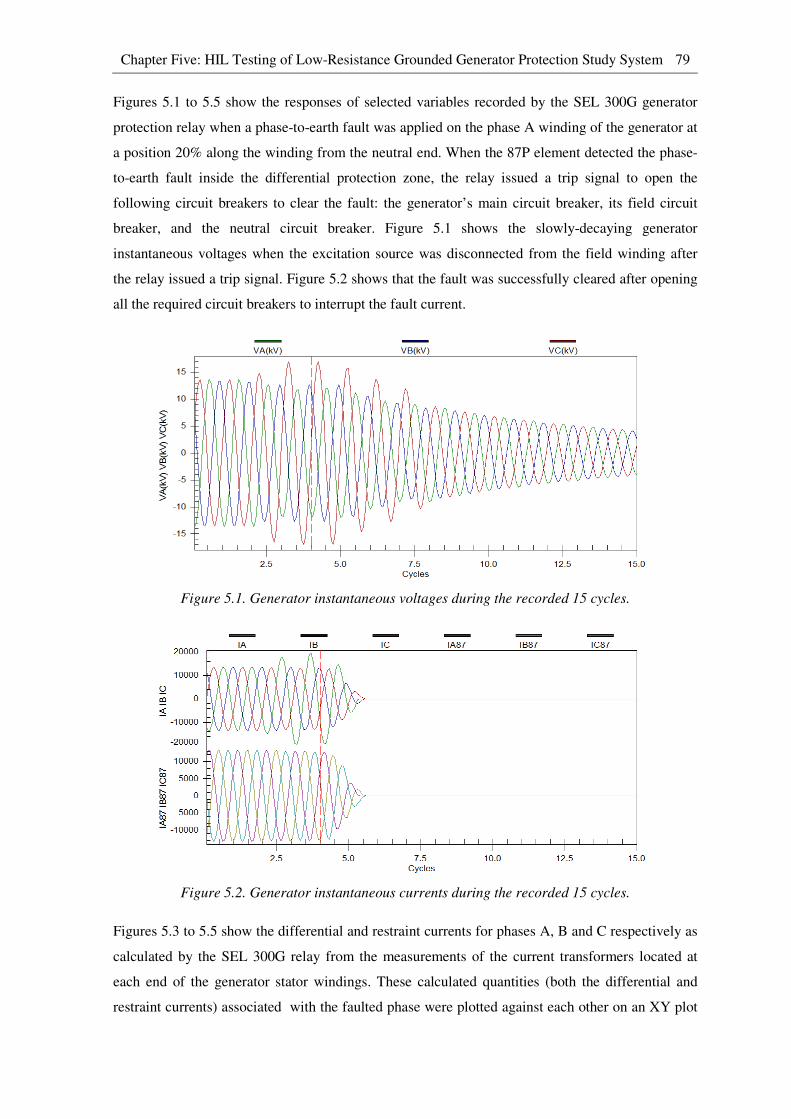
Chapter Five: HIL Testing of Low-Resistance Grounded Generator Protection Study System 79
Figures 5.1 to 5.5 show the responses of selected variables recorded by the SEL 300G generator
protection relay when a phase-to-earth fault was applied on the phase A winding of the generator at
a position 20% along the winding from the neutral end. When the 87P element detected the phase-
to-earth fault inside the differential protection zone, the relay issued a trip signal to open the
following circuit breakers to clear the fault: the generator’s main circuit breaker, its field circuit
breaker, and the neutral circuit breaker. Figure 5.1 shows the slowly-decaying generator
instantaneous voltages when the excitation source was disconnected from the field winding after
the relay issued a trip signal. Figure 5.2 shows that the fault was successfully cleared after opening
all the required circuit breakers to interrupt the fault current.
Figure 5.1. Generator instantaneous voltages during the recorded 15 cycles.
Figure 5.2. Generator instantaneous currents during the recorded 15 cycles.
Figures 5.3 to 5.5 show the differential and restraint currents for phases A, B and C respectively as
calculated by the SEL 300G relay from the measurements of the current transformers located at
each end of the generator stator windings. These calculated quantities (both the differential and
restraint currents) associated with the faulted phase were plotted against each other on an XY plot

Chapter Five: HIL Testing of Low-Resistance Grounded Generator Protection Study System 80
in order to determine the differential versus restraint current trajectory upon which the 87P element
based its tripping decisions.
Figure 5.3. Phase A operating and restraint currents during a phase A internal winding fault.
Figure 5.4. Phase B differential and restraint currents during a phase A internal winding fault.
Figure 5.5. Phase C differential and restraint currents during a phase A internal winding fault.

Chapter Five: HIL Testing of Low-Resistance Grounded Generator Protection Study System 81
Figure 5.6 shows the plot of the differential versus restraint current trajectory for phase A during
the fault, overlaid on to the dual slope differential characteristic settings chosen for the 87P element
in this case. As can be seen from Figure 5.6, the differential versus restraint current trajectory
passed into the tripping area of the dual slope differential characteristic during the fault which
caused the relay to issue a trip signal. After the fault was cleared, the differential versus restraint
current trajectory returned to the origin on the XY plot. Plots similar to Figure 5.6 can be created
for phase B and C using the method described above. However, since these two phases were
healthy, the differential versus restraint current trajectory remained in the restraining area of the
dual slope differential characteristic.
Figure 5.6. Plot of phase A differential versus restraint current during a phase A fault (Internal
winding fault at 20% of the stator winding from generator neutral).
Figures 5.7 and 5.8 show plots of the differential versus restraint current trajectories for phase A
when phase-to-earth faults were applied on the phase A winding at positions 95% and 10% from
the neutral end respectively. These two plots demonstrate the different magnitudes of the
differential current obtained when a phase-to-earth fault occurs at different locations along the
stator winding. As can be seen from Figure 5.7, when the phase-to-earth fault occurred near the
generator terminal, the magnitude of the differential current was sufficient to cause the differential
versus restraint current trajectory to pass into the tripping area of the dual slope differential
characteristic. However, when the location of the phase-to-earth fault on the stator winding was
moved towards the neutral end, the phase-to-neutral voltage imposed on the faulted section of the
winding became smaller, which resulted in smaller current that flowed into the faulted section of
the winding. As a result, there was insufficient differential current to cause the differential versus
restraint current trajectory to pass into the tripping area of the dual slope differential characteristic
as shown in Figure 5.8. For this reason, the 87P element could not detect a phase-to-earth fault on
the stator winding that occurred at or near the generator neutral.
0 2 4 6 8 10 12 140
2
4
6
8
10
12
Restraint Current (pu)
Diffe
rential C
urr
ent
(pu)
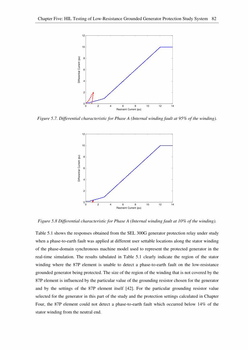
Chapter Five: HIL Testing of Low-Resistance Grounded Generator Protection Study System 82
Figure 5.7. Differential characteristic for Phase A (Internal winding fault at 95% of the winding).
Figure 5.8 Differential characteristic for Phase A (Internal winding fault at 10% of the winding).
Table 5.1 shows the responses obtained from the SEL 300G generator protection relay under study
when a phase-to-earth fault was applied at different user settable locations along the stator winding
of the phase-domain synchronous machine model used to represent the protected generator in the
real-time simulation. The results tabulated in Table 5.1 clearly indicate the region of the stator
winding where the 87P element is unable to detect a phase-to-earth fault on the low-resistance
grounded generator being protected. The size of the region of the winding that is not covered by the
87P element is influenced by the particular value of the grounding resistor chosen for the generator
and by the settings of the 87P element itself [42]. For the particular grounding resistor value
selected for the generator in this part of the study and the protection settings calculated in Chapter
Four, the 87P element could not detect a phase-to-earth fault which occurred below 14% of the
stator winding from the neutral end.
0 2 4 6 8 10 12 140
2
4
6
8
10
12
Restraint Current (pu)
Diffe
rential C
urr
ent
(pu)
0 2 4 6 8 10 12 140
2
4
6
8
10
12
Restraint Current (pu)
Diffe
rential C
urr
ent
(pu)
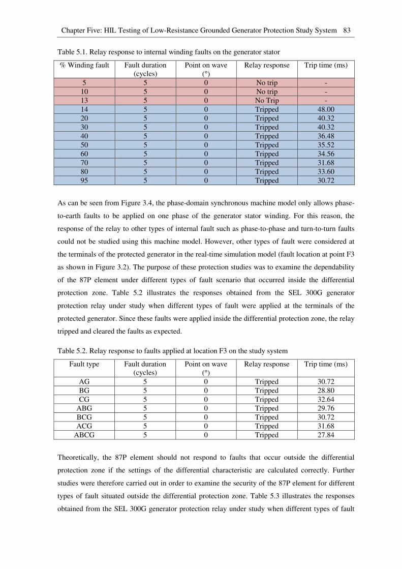
Chapter Five: HIL Testing of Low-Resistance Grounded Generator Protection Study System 83
Table 5.1. Relay response to internal winding faults on the generator stator
% Winding fault Fault duration
(cycles)
Point on wave
(°) Relay response Trip time (ms)
5 5 0 No trip -
10 5 0 No trip -
13 5 0 No Trip -
14 5 0 Tripped 48.00
20 5 0 Tripped 40.32
30 5 0 Tripped 40.32
40 5 0 Tripped 36.48
50 5 0 Tripped 35.52
60 5 0 Tripped 34.56
70 5 0 Tripped 31.68
80 5 0 Tripped 33.60
95 5 0 Tripped 30.72
As can be seen from Figure 3.4, the phase-domain synchronous machine model only allows phase-
to-earth faults to be applied on one phase of the generator stator winding. For this reason, the
response of the relay to other types of internal fault such as phase-to-phase and turn-to-turn faults
could not be studied using this machine model. However, other types of fault were considered at
the terminals of the protected generator in the real-time simulation model (fault location at point F3
as shown in Figure 3.2). The purpose of these protection studies was to examine the dependability
of the 87P element under different types of fault scenario that occurred inside the differential
protection zone. Table 5.2 illustrates the responses obtained from the SEL 300G generator
protection relay under study when different types of fault were applied at the terminals of the
protected generator. Since these faults were applied inside the differential protection zone, the relay
tripped and cleared the faults as expected.
Table 5.2. Relay response to faults applied at location F3 on the study system
Fault type Fault duration
(cycles)
Point on wave
(°) Relay response Trip time (ms)
AG 5 0 Tripped 30.72
BG 5 0 Tripped 28.80
CG 5 0 Tripped 32.64
ABG 5 0 Tripped 29.76
BCG 5 0 Tripped 30.72
ACG 5 0 Tripped 31.68
ABCG 5 0 Tripped 27.84
Theoretically, the 87P element should not respond to faults that occur outside the differential
protection zone if the settings of the differential characteristic are calculated correctly. Further
studies were therefore carried out in order to examine the security of the 87P element for different
types of fault situated outside the differential protection zone. Table 5.3 illustrates the responses
obtained from the SEL 300G generator protection relay under study when different types of fault

Chapter Five: HIL Testing of Low-Resistance Grounded Generator Protection Study System 84
were applied at the end of the transmission line closest to the power station (fault location at point
F1 as shown in Figure 3.2). The results tabulated in Table 5.3 indicate no misoperation under
different through-fault conditions and hence the protection settings of the differential characteristic
were verified. Any relay misoperation under through-fault conditions would indicate incorrect
settings of the differential characteristic and re-evaluation of the protection settings would then be
necessary.
Table 5.3. Relay response to faults applied at location F1 on the study system
Fault type Fault duration
(cycles)
Point on wave
(°) Relay response Trip time (ms)
AG 5 0 No trip -
BG 5 0 No trip -
CG 5 0 No trip -
ABG 5 0 No trip -
BCG 5 0 No trip -
ACG 5 0 No trip -
ABCG 5 0 No trip -
A more realistic CT magnetizing curve would be required in order to study the effect of CT
saturation during heavy through-fault conditions. When a CT saturates, it can no longer faithfully
reproduce the primary current with a scale factor on the secondary side of the CT. As a result, very
high differential current can be obtained that can cause misoperation of the 87P element if the
second slope of the differential characteristic is not set correctly.
5.2.2 Performance of the 87P element when configured to protect both the generator and
GSU transformer
The purpose of the protection studies conducted in this section was to examine the performance of
the 87P element when both the low-resistance grounded 555 MVA generator and the GSU
transformer were included in the differential protection zone. For the protection studies carried out
in this section, the operating conditions of the generators in the power station were the same as
described in Section 5.2.1.
As discussed in Chapter Four, there are more setting considerations for the 87P element when the
GSU transformer is included in the differential protection zone, namely CT ratio correction factor
and phase shift compensation. Incorrect settings of these two relay inputs may result in high
differential current that could cause misoperation of the 87P element. Figure 5.9 shows the
differential and restraint currents recorded by the SEL 300G relay on the healthy phase C during a
phase-to-earth fault on the phase A winding of the protected generator. This figure demonstrates
that both the CT ratio mismatch and phase shift between the primary and secondary currents of the
GSU transformer due to its delta-star configuration were correctly compensated by the relay. The

Chapter Five: HIL Testing of Low-Resistance Grounded Generator Protection Study System 85
differential current of 0.01 pu seen in Figure 5.9 corresponds to the value of the magnetizing
current of the GSU transformer (1%) that was represented in the real-time simulation model.
Figure 5.9. Phase C differential and restraint currents during a phase A internal winding fault.
Table 5.4 illustrates the responses obtained from the SEL 300G generator protection relay under
study when a phase-to-earth fault was applied at different locations along the stator winding of the
generator. By comparing Table 5.1 and Table 5.4, one can see that the performance of the 87P
element was not influenced by including the GSU transformer in the differential protection zone.
Table 5.4. Relay response to internal winding faults on the generator stator
% Winding fault Fault duration
(cycles)
Point on wave
(°) Relay response Trip time (ms)
5 5 0 No trip -
10 5 0 No trip -
13 5 0 No Trip -
14 5 0 Tripped 47.00
20 5 0 Tripped 43.20
30 5 0 Tripped 40.32
40 5 0 Tripped 40.32
50 5 0 Tripped 35.52
60 5 0 Tripped 31.68
70 5 0 Tripped 34.56
80 5 0 Tripped 32.64
95 5 0 Tripped 32.64
Using the three-phase faulted transformer model represented in the real-time simulation model
shown in Figure 3.6, the performance of the SEL 300G generator protection relay in response to
different types of transformer internal winding fault could also be studied. Tables 5.5 and 5.6 show
the HIL test results of the SEL 300G generator protection relay when turn-to-ground faults and
turn-to-turn faults were applied at different locations on the primary winding of the GSU
transformer respectively. As can be seen from Table 5.6, the 87P element was not able to detect a
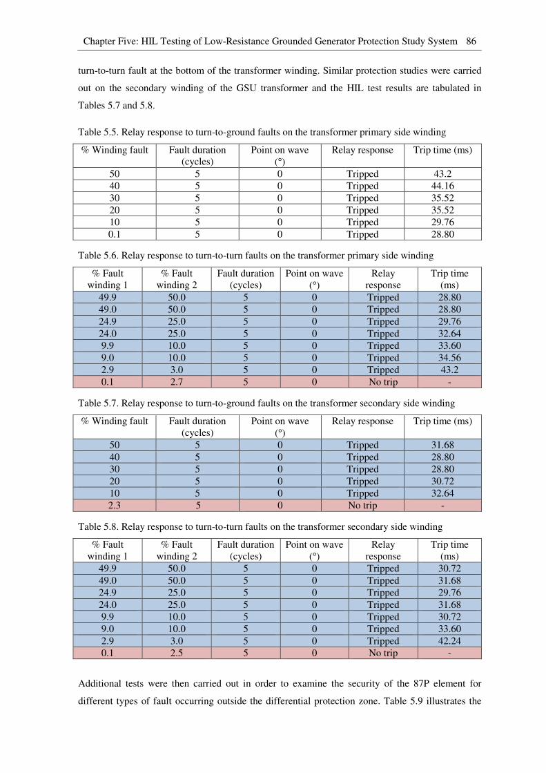
Chapter Five: HIL Testing of Low-Resistance Grounded Generator Protection Study System 86
turn-to-turn fault at the bottom of the transformer winding. Similar protection studies were carried
out on the secondary winding of the GSU transformer and the HIL test results are tabulated in
Tables 5.7 and 5.8.
Table 5.5. Relay response to turn-to-ground faults on the transformer primary side winding
% Winding fault Fault duration
(cycles)
Point on wave
(°) Relay response Trip time (ms)
50 5 0 Tripped 43.2
40 5 0 Tripped 44.16
30 5 0 Tripped 35.52
20 5 0 Tripped 35.52
10 5 0 Tripped 29.76
0.1 5 0 Tripped 28.80
Table 5.6. Relay response to turn-to-turn faults on the transformer primary side winding
% Fault
winding 1
% Fault
winding 2
Fault duration
(cycles)
Point on wave
(°) Relay
response
Trip time
(ms)
49.9 50.0 5 0 Tripped 28.80
49.0 50.0 5 0 Tripped 28.80
24.9 25.0 5 0 Tripped 29.76
24.0 25.0 5 0 Tripped 32.64
9.9 10.0 5 0 Tripped 33.60
9.0 10.0 5 0 Tripped 34.56
2.9 3.0 5 0 Tripped 43.2
0.1 2.7 5 0 No trip -
Table 5.7. Relay response to turn-to-ground faults on the transformer secondary side winding
% Winding fault Fault duration
(cycles)
Point on wave
(°) Relay response Trip time (ms)
50 5 0 Tripped 31.68
40 5 0 Tripped 28.80
30 5 0 Tripped 28.80
20 5 0 Tripped 30.72
10 5 0 Tripped 32.64
2.3 5 0 No trip -
Table 5.8. Relay response to turn-to-turn faults on the transformer secondary side winding
% Fault
winding 1
% Fault
winding 2
Fault duration
(cycles)
Point on wave
(°) Relay
response
Trip time
(ms)
49.9 50.0 5 0 Tripped 30.72
49.0 50.0 5 0 Tripped 31.68
24.9 25.0 5 0 Tripped 29.76
24.0 25.0 5 0 Tripped 31.68
9.9 10.0 5 0 Tripped 30.72
9.0 10.0 5 0 Tripped 33.60
2.9 3.0 5 0 Tripped 42.24
0.1 2.5 5 0 No trip -
Additional tests were then carried out in order to examine the security of the 87P element for
different types of fault occurring outside the differential protection zone. Table 5.9 illustrates the

Chapter Five: HIL Testing of Low-Resistance Grounded Generator Protection Study System 87
responses obtained from the SEL 300G relay when different types of fault were applied at the end
of the transmission line closest to the power station (fault location F1 shown in Figure 3.2). The
results show no relay misoperation under any through-fault conditions which indicate that the
settings of the differential characteristic are secure.
Table 5.9. Relay response to faults applied at location F1 on the study system
Fault type Fault duration
(cycles)
Point on wave
(°) Relay response Trip time (ms)
AG 5 0 No trip -
BG 5 0 No trip -
CG 5 0 No trip -
ABG 5 0 No trip -
BCG 5 0 No trip -
ACG 5 0 No trip -
ABCG 5 0 No trip -
5.2.3 Consequences of breaker failure
When the 87P element of the SEL 300G generator protection relay detects a phase-to-earth fault on
the stator winding of a low-resistance grounded generator, the relay sends a trip signal to open
various circuit breakers (i.e. generator’s main circuit breaker, field circuit breaker and neutral
circuit breaker) in order to clear the high-magnitude earth fault current. As discussed in Chapter
Three, the phase-domain synchronous machine model provides many advanced features, one of
which is to allow detailed electric representation of the external supply to the generator field circuit.
Thus, the field circuit breaker was able to be included in the real-time simulation model as shown
in Figure 3.6. Using the realistic and detailed real-time simulation model of the plant described in
Chapter Three, different scenarios of circuit breaker failure during the fault clearing process can be
studied in detail and the results can be used to understand and analyse the impact on the faulted
generator under such circumstances. Sections 5.2.3.1 to 5.2.3.3 show the results obtained from the
real-time closed-loop studies under different circuit breaker failure scenarios when clearing a
phase-to-earth fault in one phase of the stator winding of the protected generator, located 95%
along the stator winding from its neutral end.
5.2.3.1 Neutral and field breaker failure
Figures 5.10 to 5.14 show selected variables recorded during the real-time closed-loop studies
when both the neutral and field circuit breakers failed to respond to the trip signal issued by the 87P
element to clear the earth fault.
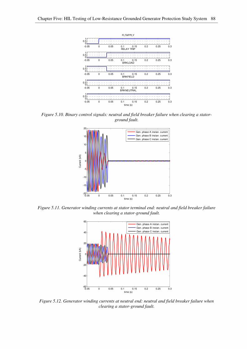
Chapter Five: HIL Testing of Low-Resistance Grounded Generator Protection Study System 88
Figure 5.10. Binary control signals: neutral and field breaker failure when clearing a stator-
ground fault.
Figure 5.11. Generator winding currents at stator terminal end: neutral and field breaker failure
when clearing a stator-ground fault.
Figure 5.12. Generator winding currents at neutral end: neutral and field breaker failure when
clearing a stator-ground fault.
-0.05 0 0.05 0.1 0.15 0.2 0.25 0.3
00.5
1
FLTAPPLY
-0.05 0 0.05 0.1 0.15 0.2 0.25 0.3
00.5
1
RELAY TRIP
-0.05 0 0.05 0.1 0.15 0.2 0.25 0.3
00.5
1
BRKLOAD
-0.05 0 0.05 0.1 0.15 0.2 0.25 0.3
00.5
1
BRKFIELD
-0.05 0 0.05 0.1 0.15 0.2 0.25 0.3
00.5
1
time (s)
BRKNEUTRAL
-0.05 0 0.05 0.1 0.15 0.2 0.25 0.3-20
-15
-10
-5
0
5
10
15
20
time (s)
Curr
ent
(kA
)
Gen. phase A instan. current
Gen. phase B instan. current
Gen. phase C instan. current
-0.05 0 0.05 0.1 0.15 0.2 0.25 0.3-60
-40
-20
0
20
40
60
time (s)
Curr
ent
(kA
)
Gen. phase A instan. current
Gen. phase B instan. current
Gen. phase C instan. current
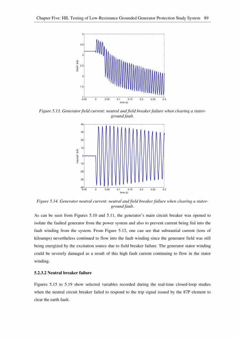
Chapter Five: HIL Testing of Low-Resistance Grounded Generator Protection Study System 89
Figure 5.13. Generator field current: neutral and field breaker failure when clearing a stator-
ground fault.
Figure 5.14. Generator neutral current: neutral and field breaker failure when clearing a stator-
ground fault.
As can be seen from Figures 5.10 and 5.11, the generator’s main circuit breaker was opened to
isolate the faulted generator from the power system and also to prevent current being fed into the
fault winding from the system. From Figure 5.12, one can see that substantial current (tens of
kiloamps) nevertheless continued to flow into the fault winding since the generator field was still
being energized by the excitation source due to field breaker failure. The generator stator winding
could be severely damaged as a result of this high fault current continuing to flow in the stator
winding.
5.2.3.2 Neutral breaker failure
Figures 5.15 to 5.19 show selected variables recorded during the real-time closed-loop studies
when the neutral circuit breaker failed to respond to the trip signal issued by the 87P element to
clear the earth fault.
-0.05 0 0.05 0.1 0.15 0.2 0.25 0.31
1.5
2
2.5
3
3.5
4
time (s)
Ifie
ld1 (
kA
)
-0.05 0 0.05 0.1 0.15 0.2 0.25 0.3-40
-30
-20
-10
0
10
20
30
40
time (s)
Ineutr
al1
(kA
)

Chapter Five: HIL Testing of Low-Resistance Grounded Generator Protection Study System 90
Figure 5.15. Binary control signals: neutral breaker failure when clearing a stator-ground fault.
Figure 5.16. Generator winding currents at stator terminal end: neutral breaker failure when
clearing a stator-ground fault.
Figure 5.17. Generator winding currents at neutral end: neutral breaker failure when clearing a
stator-ground fault.
-0.05 0 0.05 0.1 0.15 0.2 0.25 0.3
00.5
1
FLTAPPLY
-0.05 0 0.05 0.1 0.15 0.2 0.25 0.3
00.5
1
RELAY TRIP
-0.05 0 0.05 0.1 0.15 0.2 0.25 0.3
00.5
1
BRKLOAD
-0.05 0 0.05 0.1 0.15 0.2 0.25 0.3
00.5
1
BRKFIELD
-0.05 0 0.05 0.1 0.15 0.2 0.25 0.3
00.5
1
time (s)
BRKNEUTRAL
-0.05 0 0.05 0.1 0.15 0.2 0.25 0.3-20
-15
-10
-5
0
5
10
15
20
time (s)
Curr
ent
(kA
)
Gen. phase A instan. current
Gen. phase B instan. current
Gen. phase C instan. current
-0.05 0 0.05 0.1 0.15 0.2 0.25 0.3-60
-40
-20
0
20
40
60
time (s)
Curr
ent
(kA
)
Gen. phase A instan. current
Gen. phase B instan. current
Gen. phase C instan. current
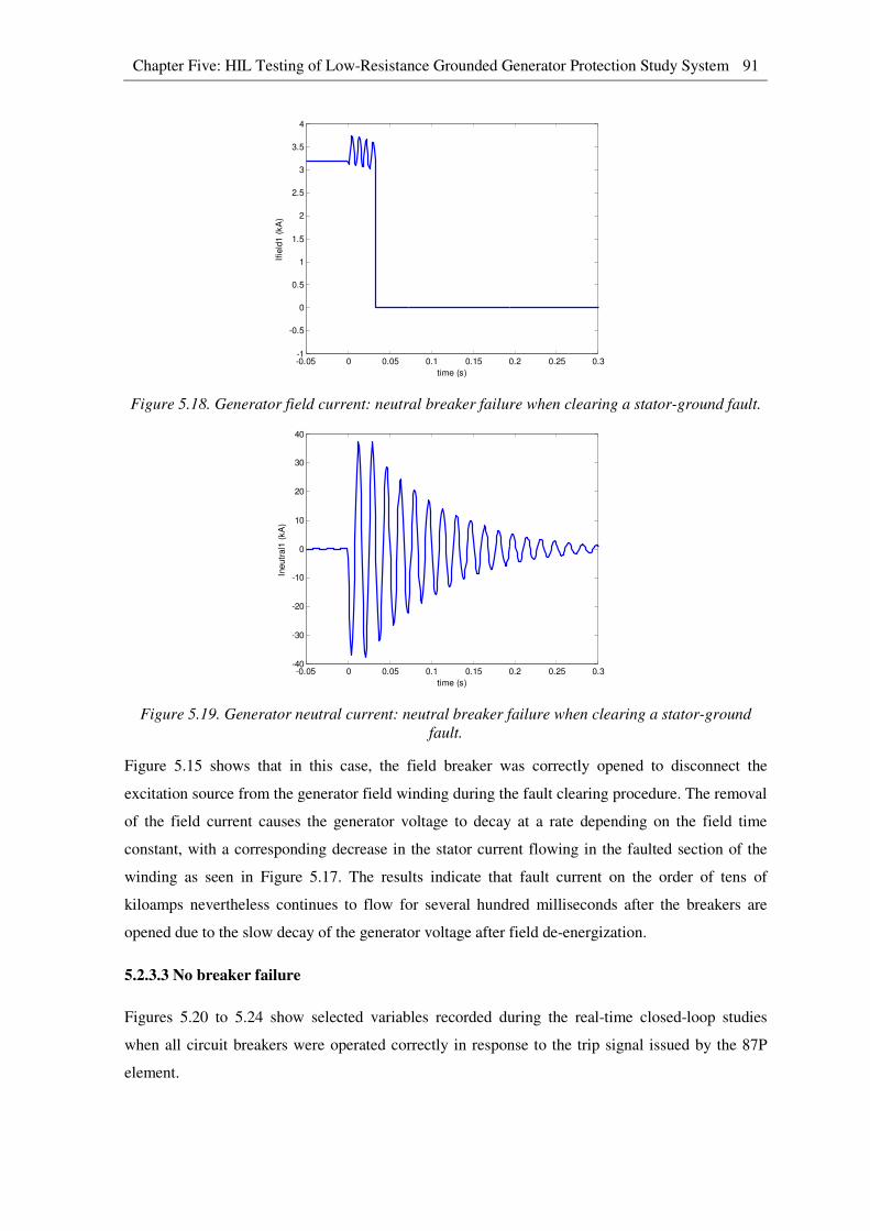
Chapter Five: HIL Testing of Low-Resistance Grounded Generator Protection Study System 91
Figure 5.18. Generator field current: neutral breaker failure when clearing a stator-ground fault.
Figure 5.19. Generator neutral current: neutral breaker failure when clearing a stator-ground
fault.
Figure 5.15 shows that in this case, the field breaker was correctly opened to disconnect the
excitation source from the generator field winding during the fault clearing procedure. The removal
of the field current causes the generator voltage to decay at a rate depending on the field time
constant, with a corresponding decrease in the stator current flowing in the faulted section of the
winding as seen in Figure 5.17. The results indicate that fault current on the order of tens of
kiloamps nevertheless continues to flow for several hundred milliseconds after the breakers are
opened due to the slow decay of the generator voltage after field de-energization.
5.2.3.3 No breaker failure
Figures 5.20 to 5.24 show selected variables recorded during the real-time closed-loop studies
when all circuit breakers were operated correctly in response to the trip signal issued by the 87P
element.
-0.05 0 0.05 0.1 0.15 0.2 0.25 0.3-1
-0.5
0
0.5
1
1.5
2
2.5
3
3.5
4
time (s)
Ifie
ld1 (
kA
)
-0.05 0 0.05 0.1 0.15 0.2 0.25 0.3-40
-30
-20
-10
0
10
20
30
40
time (s)
Ineutr
al1
(kA
)
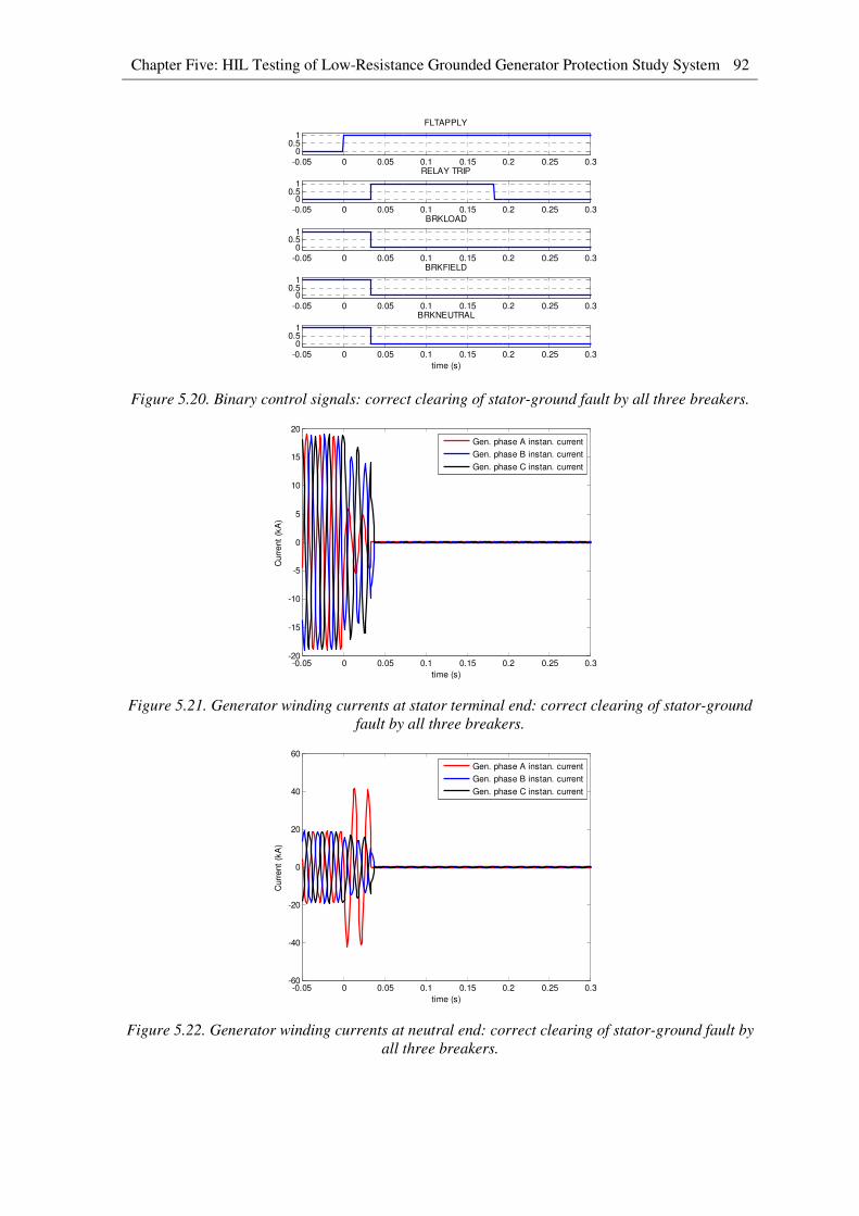
Chapter Five: HIL Testing of Low-Resistance Grounded Generator Protection Study System 92
Figure 5.20. Binary control signals: correct clearing of stator-ground fault by all three breakers.
Figure 5.21. Generator winding currents at stator terminal end: correct clearing of stator-ground
fault by all three breakers.
Figure 5.22. Generator winding currents at neutral end: correct clearing of stator-ground fault by
all three breakers.
-0.05 0 0.05 0.1 0.15 0.2 0.25 0.3
00.5
1
FLTAPPLY
-0.05 0 0.05 0.1 0.15 0.2 0.25 0.3
00.5
1
RELAY TRIP
-0.05 0 0.05 0.1 0.15 0.2 0.25 0.3
00.5
1
BRKLOAD
-0.05 0 0.05 0.1 0.15 0.2 0.25 0.3
00.5
1
BRKFIELD
-0.05 0 0.05 0.1 0.15 0.2 0.25 0.3
00.5
1
time (s)
BRKNEUTRAL
-0.05 0 0.05 0.1 0.15 0.2 0.25 0.3-20
-15
-10
-5
0
5
10
15
20
time (s)
Curr
ent
(kA
)
Gen. phase A instan. current
Gen. phase B instan. current
Gen. phase C instan. current
-0.05 0 0.05 0.1 0.15 0.2 0.25 0.3-60
-40
-20
0
20
40
60
time (s)
Curr
ent
(kA
)
Gen. phase A instan. current
Gen. phase B instan. current
Gen. phase C instan. current
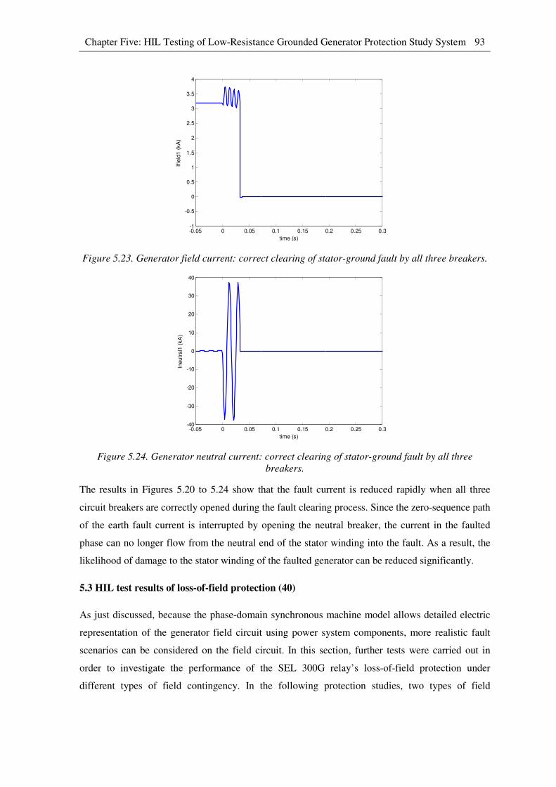
Chapter Five: HIL Testing of Low-Resistance Grounded Generator Protection Study System 93
Figure 5.23. Generator field current: correct clearing of stator-ground fault by all three breakers.
Figure 5.24. Generator neutral current: correct clearing of stator-ground fault by all three
breakers.
The results in Figures 5.20 to 5.24 show that the fault current is reduced rapidly when all three
circuit breakers are correctly opened during the fault clearing process. Since the zero-sequence path
of the earth fault current is interrupted by opening the neutral breaker, the current in the faulted
phase can no longer flow from the neutral end of the stator winding into the fault. As a result, the
likelihood of damage to the stator winding of the faulted generator can be reduced significantly.
5.3 HIL test results of loss-of-field protection (40)
As just discussed, because the phase-domain synchronous machine model allows detailed electric
representation of the generator field circuit using power system components, more realistic fault
scenarios can be considered on the field circuit. In this section, further tests were carried out in
order to investigate the performance of the SEL 300G relay’s loss-of-field protection under
different types of field contingency. In the following protection studies, two types of field
-0.05 0 0.05 0.1 0.15 0.2 0.25 0.3-1
-0.5
0
0.5
1
1.5
2
2.5
3
3.5
4
time (s)
Ifie
ld1 (
kA
)
-0.05 0 0.05 0.1 0.15 0.2 0.25 0.3-40
-30
-20
-10
0
10
20
30
40
time (s)
Ineutr
al1
(kA
)
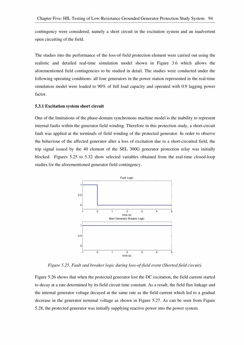
Chapter Five: HIL Testing of Low-Resistance Grounded Generator Protection Study System 94
contingency were considered, namely a short circuit in the excitation system and an inadvertent
open circuiting of the field.
The studies into the performance of the loss-of-field protection element were carried out using the
realistic and detailed real-time simulation model shown in Figure 3.6 which allows the
aforementioned field contingencies to be studied in detail. The studies were conducted under the
following operating conditions: all four generators in the power station represented in the real-time
simulation model were loaded to 90% of full load capacity and operated with 0.9 lagging power
factor.
5.3.1 Excitation system short circuit
One of the limitations of the phase-domain synchronous machine model is the inability to represent
internal faults within the generator field winding. Therefore in this protection study, a short-circuit
fault was applied at the terminals of field winding of the protected generator. In order to observe
the behaviour of the affected generator after a loss of excitation due to a short-circuited field, the
trip signal issued by the 40 element of the SEL 300G generator protection relay was initially
blocked. Figures 5.25 to 5.32 show selected variables obtained from the real-time closed-loop
studies for the aforementioned generator field contingency.
Figure 5.25. Fault and breaker logic during loss-of-field event (Shorted field circuit).
Figure 5.26 shows that when the protected generator lost the DC excitation, the field current started
to decay at a rate determined by its field circuit time constant. As a result, the field flux linkage and
the internal generator voltage decayed at the same rate as the field current which led to a gradual
decrease in the generator terminal voltage as shown in Figure 5.27. As can be seen from Figure
5.28, the protected generator was initially supplying reactive power into the power system.
-1 0 1 2 3 4 5
0
0.5
1
Fault Logic
time (s)
-1 0 1 2 3 4 5
0
0.5
1
Main Generator Breaker Logic
time (s)
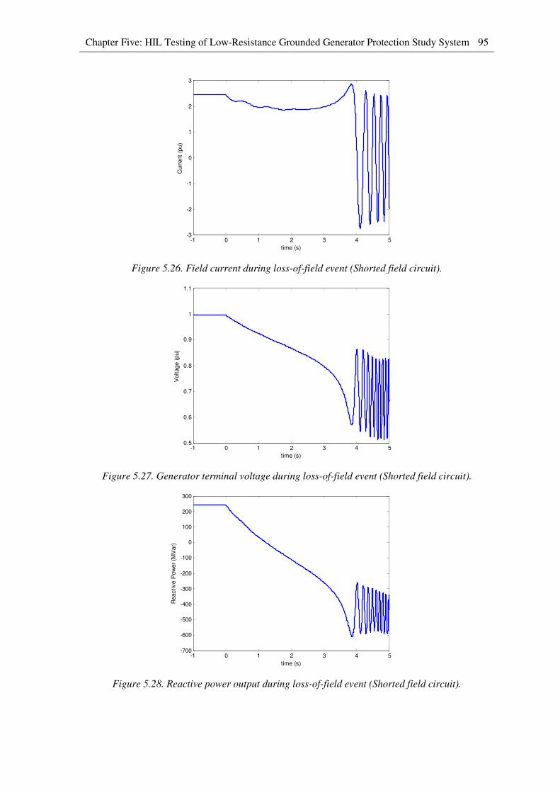
Chapter Five: HIL Testing of Low-Resistance Grounded Generator Protection Study System 95
Figure 5.26. Field current during loss-of-field event (Shorted field circuit).
Figure 5.27. Generator terminal voltage during loss-of-field event (Shorted field circuit).
Figure 5.28. Reactive power output during loss-of-field event (Shorted field circuit).
-1 0 1 2 3 4 5-3
-2
-1
0
1
2
3
time (s)
Curr
ent
(pu)
-1 0 1 2 3 4 50.5
0.6
0.7
0.8
0.9
1
1.1
time (s)
Voltage (
pu)
-1 0 1 2 3 4 5-700
-600
-500
-400
-300
-200
-100
0
100
200
300
time (s)
Reactive P
ow
er
(MV
ar)

Chapter Five: HIL Testing of Low-Resistance Grounded Generator Protection Study System 96
Figure 5.29. Active power output during loss-of-field event (Shorted field circuit).
Figure 5.30. Generator load angle during loss-of-field event (Shorted field circuit).
Figure 5.31. Generator instantaneous voltages during loss-of-field event (Shorted field circuit).
-1 0 1 2 3 4 5-300
-200
-100
0
100
200
300
400
500
600
time (s)
Active P
ow
er
(MW
)
-1 0 1 2 3 4 5-200
-150
-100
-50
0
50
100
150
200
250
time (s)
Load A
ngle
(δ)
-1 0 1 2 3 4 5-20
-15
-10
-5
0
5
10
15
20
time (s)
Voltage (
kV
)
Gen. phase A instan. voltage
Gen. phase B instan. voltage
Gen. phase C instan. voltage
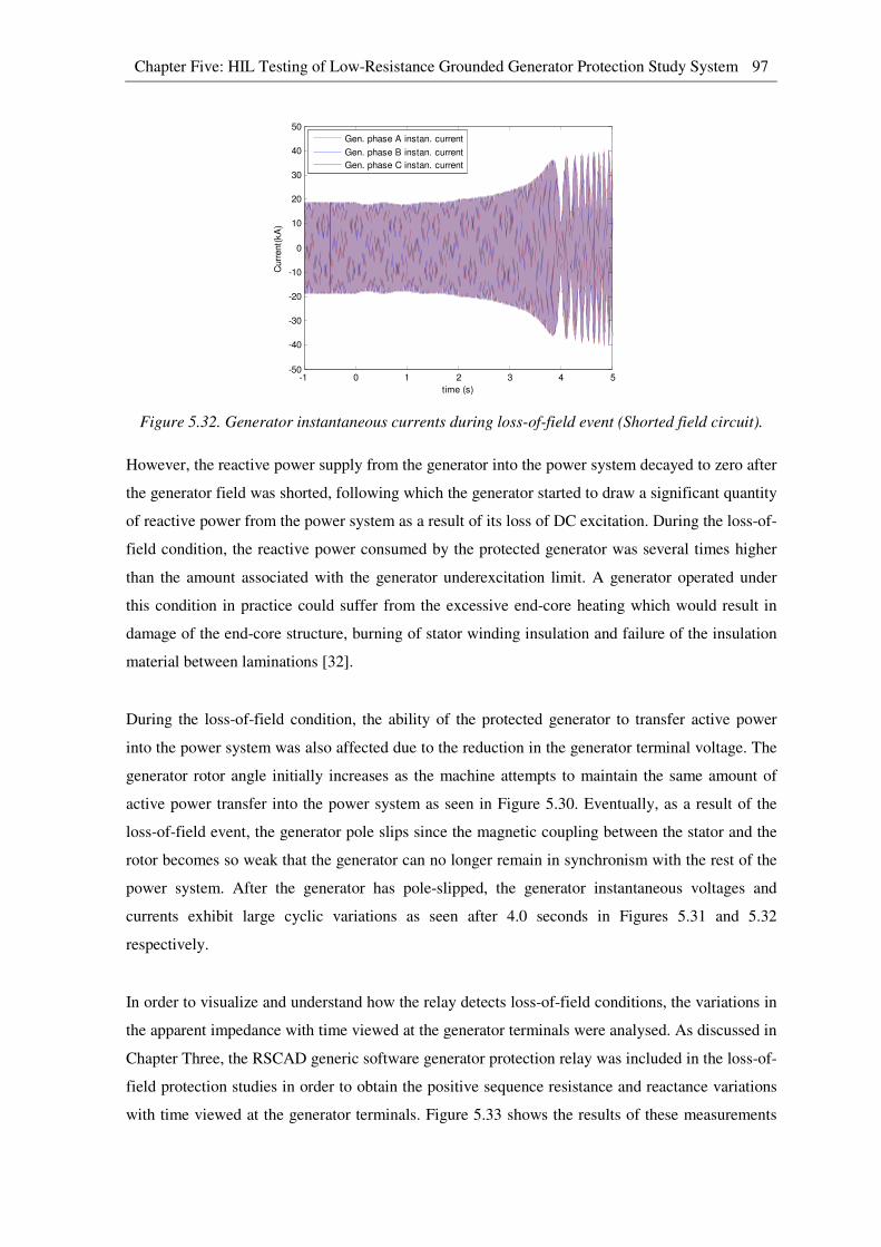
Chapter Five: HIL Testing of Low-Resistance Grounded Generator Protection Study System 97
Figure 5.32. Generator instantaneous currents during loss-of-field event (Shorted field circuit).
However, the reactive power supply from the generator into the power system decayed to zero after
the generator field was shorted, following which the generator started to draw a significant quantity
of reactive power from the power system as a result of its loss of DC excitation. During the loss-of-
field condition, the reactive power consumed by the protected generator was several times higher
than the amount associated with the generator underexcitation limit. A generator operated under
this condition in practice could suffer from the excessive end-core heating which would result in
damage of the end-core structure, burning of stator winding insulation and failure of the insulation
material between laminations [32].
During the loss-of-field condition, the ability of the protected generator to transfer active power
into the power system was also affected due to the reduction in the generator terminal voltage. The
generator rotor angle initially increases as the machine attempts to maintain the same amount of
active power transfer into the power system as seen in Figure 5.30. Eventually, as a result of the
loss-of-field event, the generator pole slips since the magnetic coupling between the stator and the
rotor becomes so weak that the generator can no longer remain in synchronism with the rest of the
power system. After the generator has pole-slipped, the generator instantaneous voltages and
currents exhibit large cyclic variations as seen after 4.0 seconds in Figures 5.31 and 5.32
respectively.
In order to visualize and understand how the relay detects loss-of-field conditions, the variations in
the apparent impedance with time viewed at the generator terminals were analysed. As discussed in
Chapter Three, the RSCAD generic software generator protection relay was included in the loss-of-
field protection studies in order to obtain the positive sequence resistance and reactance variations
with time viewed at the generator terminals. Figure 5.33 shows the results of these measurements
-1 0 1 2 3 4 5-50
-40
-30
-20
-10
0
10
20
30
40
50
time (s)
Curr
ent(
kA
)
Gen. phase A instan. current
Gen. phase B instan. current
Gen. phase C instan. current
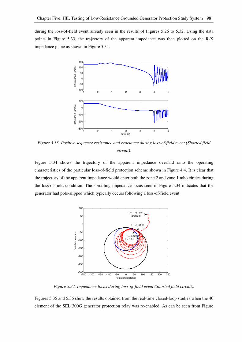
Chapter Five: HIL Testing of Low-Resistance Grounded Generator Protection Study System 98
during the loss-of-field event already seen in the results of Figures 5.26 to 5.32. Using the data
points in Figure 5.33, the trajectory of the apparent impedance was then plotted on the R-X
impedance plane as shown in Figure 5.34.
Figure 5.33. Positive sequence resistance and reactance during loss-of-field event (Shorted field
circuit).
Figure 5.34 shows the trajectory of the apparent impedance overlaid onto the operating
characteristics of the particular loss-of-field protection scheme shown in Figure 4.4. It is clear that
the trajectory of the apparent impedance would enter both the zone 2 and zone 1 mho circles during
the loss-of-field condition. The spiralling impedance locus seen in Figure 5.34 indicates that the
generator had pole-slipped which typically occurs following a loss-of-field event.
Figure 5.34. Impedance locus during loss-of-field event (Shorted field circuit).
Figures 5.35 and 5.36 show the results obtained from the real-time closed-loop studies when the 40
element of the SEL 300G generator protection relay was re-enabled. As can be seen from Figure
-1 0 1 2 3 4 5-100
-50
0
50
100
150
Resis
tance (
ohm
s)
-1 0 1 2 3 4 5-300
-200
-100
0
100
Reacta
nce (
ohm
s)
time (s)
-250 -200 -150 -100 -50 0 50 100 150 200 250-300
-250
-200
-150
-100
-50
0
50
100
Resistance(ohms)
Reacta
nce(o
hm
s)
t = -1.0 - 0 s
(prefault)
t = 3.135 s
t = 5.0 s
t = 3.524 s
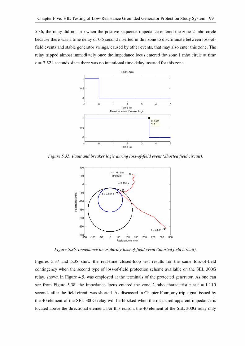
Chapter Five: HIL Testing of Low-Resistance Grounded Generator Protection Study System 99
5.36, the relay did not trip when the positive sequence impedance entered the zone 2 mho circle
because there was a time delay of 0.5 second inserted in this zone to discriminate between loss-of-
field events and stable generator swings, caused by other events, that may also enter this zone. The
relay tripped almost immediately once the impedance locus entered the zone 1 mho circle at time � = 3.524seconds since there was no intentional time delay inserted for this zone.
Figure 5.35. Fault and breaker logic during loss-of-field event (Shorted field circuit).
Figure 5.36. Impedance locus during loss-of-field event (Shorted field circuit).
Figures 5.37 and 5.38 show the real-time closed-loop test results for the same loss-of-field
contingency when the second type of loss-of-field protection scheme available on the SEL 300G
relay, shown in Figure 4.5, was employed at the terminals of the protected generator. As one can
see from Figure 5.38, the impedance locus entered the zone 2 mho characteristic at � = 1.110
seconds after the field circuit was shorted. As discussed in Chapter Four, any trip signal issued by
the 40 element of the SEL 300G relay will be blocked when the measured apparent impedance is
located above the directional element. For this reason, the 40 element of the SEL 300G relay only
-1 0 1 2 3 4 5
0
0.5
1
Fault Logic
time (s)
-1 0 1 2 3 4 5
0
0.5
1
X: 3.523
Y: 1
Main Generator Breaker Logic
time (s)
-150 -100 -50 0 50 100 150 200 250 300 350-300
-250
-200
-150
-100
-50
0
50
100
Resistance(ohms)
Reacta
nce(o
hm
s)
t = 3.544
t = 3.524 s
t = 3.135 s
t = -1.0 - 0 s
(prefault)

Chapter Five: HIL Testing of Low-Resistance Grounded Generator Protection Study System 100
issued a trip signal after the impedance had passed into the zone 1 mho characteristic and the zone
1 time delay of 0.25 seconds has elapsed.
Figure 5.37. Fault and breaker logic during loss-of-field event (Shorted field circuit).
Figure 5.38. Impedance locus during loss-of-field event (Shorted field circuit).
5.3.2 Inadvertent open circuiting of the field
Open circuiting of the generator field is another type of contingency that results in loss-of-field
conditions. In order to test the response of the relay to such a contingency, the field circuit breaker
of the protected generator represented in the real-time simulation model shown in Figure 3.6 was
deliberately opened to simulate field breaker misoperation under normal generator operating
conditions. Once again, the trip signal issued by the 40 element of the SEL 300G relay was initially
blocked in order to observe the behaviour of the affected generator during this type of field
-1 0 1 2 3 4 5
0
0.5
1
Fault Logic
time (s)
-1 0 1 2 3 4 5
0
0.5
1
X: 3.384
Y: 1
Main Generator Breaker Logic
time (s)
-300 -200 -100 0 100 200 300-300
-250
-200
-150
-100
-50
0
50
100
150
Resistance(ohms)
Reacta
nce(o
hm
s)
t = -1.0 - 0 s
(prefault)
t = 1.110 st = 2.460 s
t = 3.403 s
t = 3.384 s
t = 3.130 s
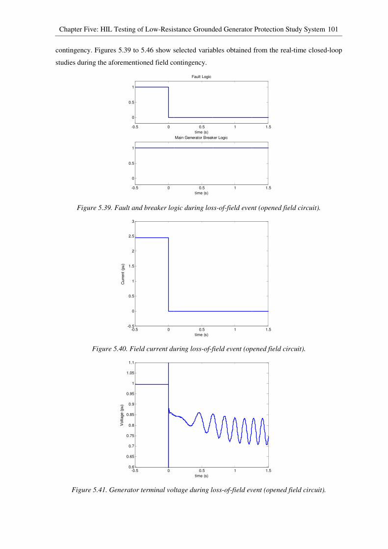
Chapter Five: HIL Testing of Low-Resistance Grounded Generator Protection Study System 101
contingency. Figures 5.39 to 5.46 show selected variables obtained from the real-time closed-loop
studies during the aforementioned field contingency.
Figure 5.39. Fault and breaker logic during loss-of-field event (opened field circuit).
Figure 5.40. Field current during loss-of-field event (opened field circuit).
Figure 5.41. Generator terminal voltage during loss-of-field event (opened field circuit).
-0.5 0 0.5 1 1.5
0
0.5
1
Fault Logic
time (s)
-0.5 0 0.5 1 1.5
0
0.5
1
Main Generator Breaker Logic
time (s)
-0.5 0 0.5 1 1.5-0.5
0
0.5
1
1.5
2
2.5
3
time (s)
Curr
ent
(pu)
-0.5 0 0.5 1 1.50.6
0.65
0.7
0.75
0.8
0.85
0.9
0.95
1
1.05
1.1
time (s)
Voltage (
pu)

Chapter Five: HIL Testing of Low-Resistance Grounded Generator Protection Study System 102
Figure 5.42. Reactive power output during loss-of-field event (opened field circuit).
Figure 5.43. Active power output during loss-of-field event (opened field circuit).
Figure 5.44. Generator load angle during loss-of-field event (opened field circuit).
-0.5 0 0.5 1 1.5-500
-400
-300
-200
-100
0
100
200
300
time (s)
Reactive P
ow
er
(MV
ar)
-0.5 0 0.5 1 1.50
100
200
300
400
500
600
time (s)
Active P
ow
er
(MW
)
-0.5 0 0.5 1 1.5-200
-150
-100
-50
0
50
100
150
200
250
time (s)
Load A
ngle
(δ)
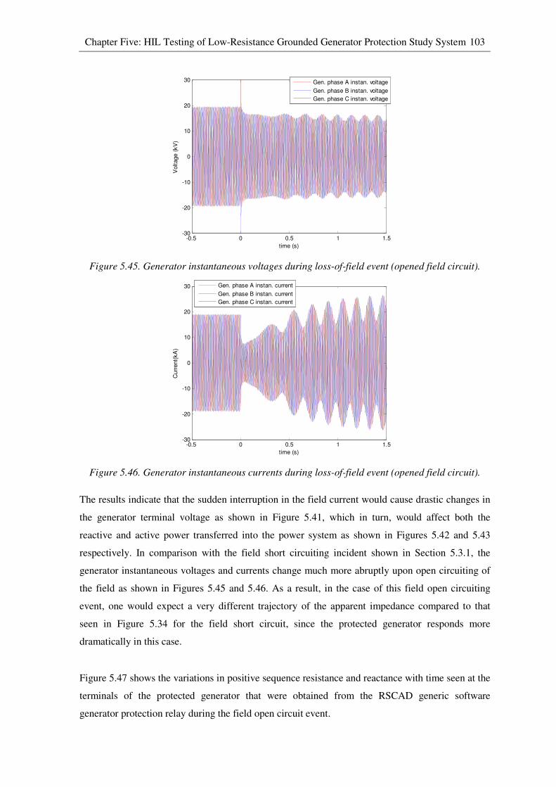
Chapter Five: HIL Testing of Low-Resistance Grounded Generator Protection Study System 103
Figure 5.45. Generator instantaneous voltages during loss-of-field event (opened field circuit).
Figure 5.46. Generator instantaneous currents during loss-of-field event (opened field circuit).
The results indicate that the sudden interruption in the field current would cause drastic changes in
the generator terminal voltage as shown in Figure 5.41, which in turn, would affect both the
reactive and active power transferred into the power system as shown in Figures 5.42 and 5.43
respectively. In comparison with the field short circuiting incident shown in Section 5.3.1, the
generator instantaneous voltages and currents change much more abruptly upon open circuiting of
the field as shown in Figures 5.45 and 5.46. As a result, in the case of this field open circuiting
event, one would expect a very different trajectory of the apparent impedance compared to that
seen in Figure 5.34 for the field short circuit, since the protected generator responds more
dramatically in this case.
Figure 5.47 shows the variations in positive sequence resistance and reactance with time seen at the
terminals of the protected generator that were obtained from the RSCAD generic software
generator protection relay during the field open circuit event.
-0.5 0 0.5 1 1.5-30
-20
-10
0
10
20
30
time (s)
Voltage (
kV
)
Gen. phase A instan. voltage
Gen. phase B instan. voltage
Gen. phase C instan. voltage
-0.5 0 0.5 1 1.5-30
-20
-10
0
10
20
30
time (s)
Curr
ent(
kA
)
Gen. phase A instan. current
Gen. phase B instan. current
Gen. phase C instan. current
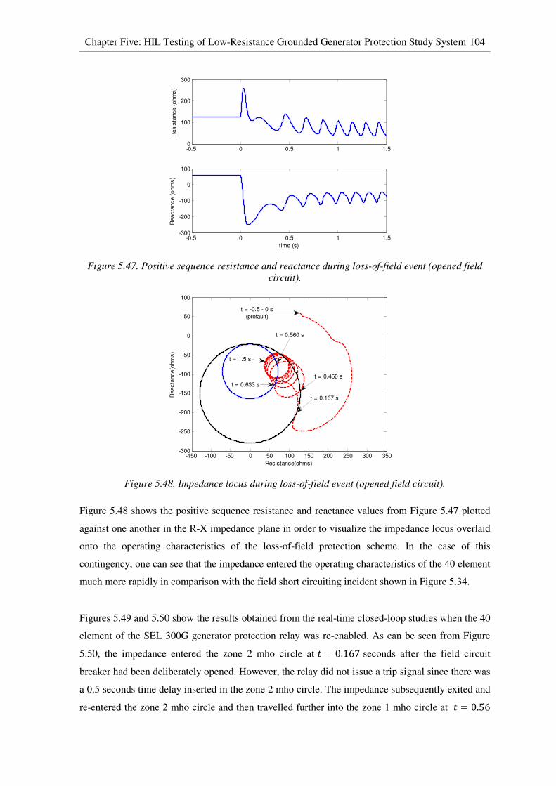
Chapter Five: HIL Testing of Low-Resistance Grounded Generator Protection Study System 104
Figure 5.47. Positive sequence resistance and reactance during loss-of-field event (opened field
circuit).
Figure 5.48. Impedance locus during loss-of-field event (opened field circuit).
Figure 5.48 shows the positive sequence resistance and reactance values from Figure 5.47 plotted
against one another in the R-X impedance plane in order to visualize the impedance locus overlaid
onto the operating characteristics of the loss-of-field protection scheme. In the case of this
contingency, one can see that the impedance entered the operating characteristics of the 40 element
much more rapidly in comparison with the field short circuiting incident shown in Figure 5.34.
Figures 5.49 and 5.50 show the results obtained from the real-time closed-loop studies when the 40
element of the SEL 300G generator protection relay was re-enabled. As can be seen from Figure
5.50, the impedance entered the zone 2 mho circle at � = 0.167 seconds after the field circuit
breaker had been deliberately opened. However, the relay did not issue a trip signal since there was
a 0.5 seconds time delay inserted in the zone 2 mho circle. The impedance subsequently exited and
re-entered the zone 2 mho circle and then travelled further into the zone 1 mho circle at � = 0.56
-0.5 0 0.5 1 1.50
100
200
300
Resis
tance (
ohm
s)
-0.5 0 0.5 1 1.5-300
-200
-100
0
100R
eacta
nce (
ohm
s)
time (s)
-150 -100 -50 0 50 100 150 200 250 300 350-300
-250
-200
-150
-100
-50
0
50
100
Resistance(ohms)
Reacta
nce(o
hm
s)
t = 0.167 s
t = 0.450 s
t = 0.633 s
t = 1.5 s
t = 0.560 s
t = -0.5 - 0 s
(prefault)
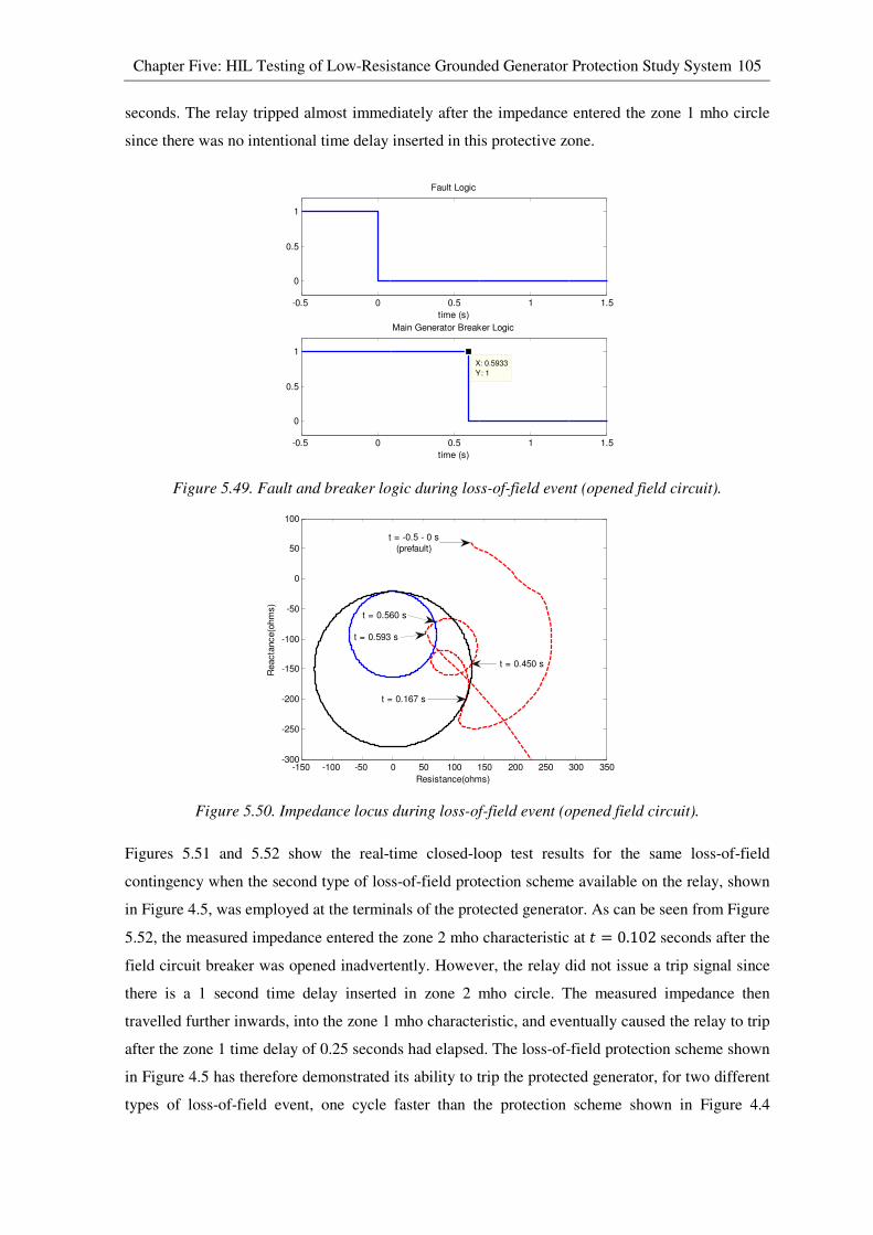
Chapter Five: HIL Testing of Low-Resistance Grounded Generator Protection Study System 105
seconds. The relay tripped almost immediately after the impedance entered the zone 1 mho circle
since there was no intentional time delay inserted in this protective zone.
Figure 5.49. Fault and breaker logic during loss-of-field event (opened field circuit).
Figure 5.50. Impedance locus during loss-of-field event (opened field circuit).
Figures 5.51 and 5.52 show the real-time closed-loop test results for the same loss-of-field
contingency when the second type of loss-of-field protection scheme available on the relay, shown
in Figure 4.5, was employed at the terminals of the protected generator. As can be seen from Figure
5.52, the measured impedance entered the zone 2 mho characteristic at � = 0.102 seconds after the
field circuit breaker was opened inadvertently. However, the relay did not issue a trip signal since
there is a 1 second time delay inserted in zone 2 mho circle. The measured impedance then
travelled further inwards, into the zone 1 mho characteristic, and eventually caused the relay to trip
after the zone 1 time delay of 0.25 seconds had elapsed. The loss-of-field protection scheme shown
in Figure 4.5 has therefore demonstrated its ability to trip the protected generator, for two different
types of loss-of-field event, one cycle faster than the protection scheme shown in Figure 4.4
-0.5 0 0.5 1 1.5
0
0.5
1
Fault Logic
time (s)
-0.5 0 0.5 1 1.5
0
0.5
1
X: 0.5933
Y: 1
Main Generator Breaker Logic
time (s)
-150 -100 -50 0 50 100 150 200 250 300 350-300
-250
-200
-150
-100
-50
0
50
100
Resistance(ohms)
Reacta
nce(o
hm
s)
t = -0.5 - 0 s
(prefault)
t = 0.167 s
t = 0.450 s
t = 0.560 s
t = 0.593 s

Chapter Five: HIL Testing of Low-Resistance Grounded Generator Protection Study System 106
because of the extended diameters of its mho circles. However, because of these extended mho
circle diameters, suitable time delays have to be selected in order to prevent misoperation under
stable generator swing conditions.
Figure 5.51. Fault and breaker logic during loss-of-field event (opened field circuit).
Figure 5.52. Impedance locus during loss-of-field event (opened field circuit).
5.3.3 Effect of different generator loading conditions during loss-of-field events
It is important to note that the trajectory of the positive sequence impedance during loss-of-field
conditions depends on the relative rates of change of the generator internal voltage and rotor angle,
which in turn, depends on the field circuit time constant and the initial generator loading condition.
For this reason, additional loss-of-field protection studies were carried out in order to investigate
the effects of generator initial loading conditions on the apparent impedance measured at the
terminals of the protected generator under different types of field contingencies.
-0.5 0 0.5 1 1.5
0
0.5
1
Fault Logic
time (s)
-0.5 0 0.5 1 1.5
0
0.5
1
X: 0.4147
Y: 1
Main Generator Breaker Logic
time (s)
-400 -300 -200 -100 0 100 200 300 400-400
-300
-200
-100
0
100
200
Resistance(ohms)
Reacta
nce(o
hm
s)
t = 0.031 s
t = -0.5 - 0 s
(prefault)
t = 0.4147
t = 0.102 s
t = 0.432 s
t = 0.159 s
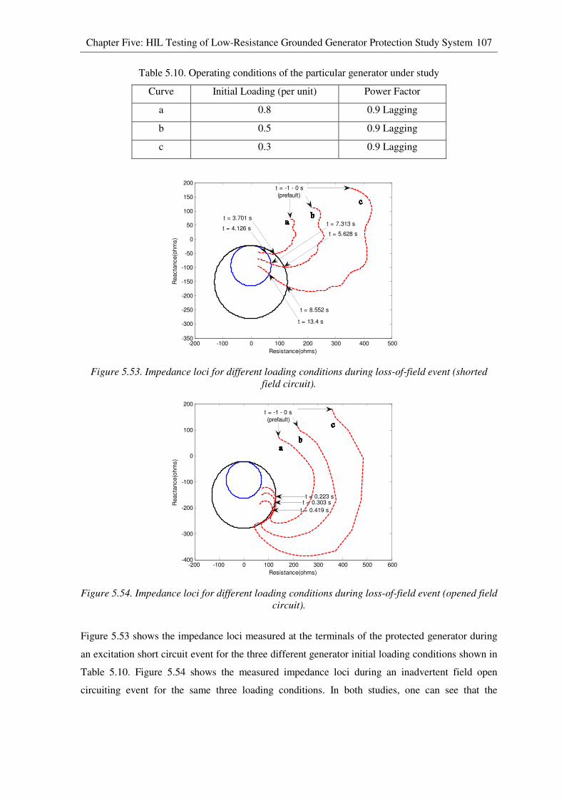
Chapter Five: HIL Testing of Low-Resistance Grounded Generator Protection Study System 107
Table 5.10. Operating conditions of the particular generator under study
Curve Initial Loading (per unit) Power Factor
a 0.8 0.9 Lagging
b 0.5 0.9 Lagging
c 0.3 0.9 Lagging
Figure 5.53. Impedance loci for different loading conditions during loss-of-field event (shorted
field circuit).
Figure 5.54. Impedance loci for different loading conditions during loss-of-field event (opened field
circuit).
Figure 5.53 shows the impedance loci measured at the terminals of the protected generator during
an excitation short circuit event for the three different generator initial loading conditions shown in
Table 5.10. Figure 5.54 shows the measured impedance loci during an inadvertent field open
circuiting event for the same three loading conditions. In both studies, one can see that the
-200 -100 0 100 200 300 400 500-350
-300
-250
-200
-150
-100
-50
0
50
100
150
200
Resistance(ohms)
Reacta
nce(o
hm
s)
t = 4.126 s
t = 3.701 s
t = -1 - 0 s
(prefault)
t = 8.552 s
t = 5.628 s
t = 7.313 s
t = 13.4 s
-200 -100 0 100 200 300 400 500 600-400
-300
-200
-100
0
100
200
Resistance(ohms)
Reacta
nce(o
hm
s)
t = -1 - 0 s
(prefault)
t = 0.223 s
t = 0.419 s
t = 0.303 s

Chapter Five: HIL Testing of Low-Resistance Grounded Generator Protection Study System 108
impedance locus moved more quickly into the loss-of-field mho characteristics as the initial steady-
state loading on the generator was increased.
5.4 HIL test results of out-of-step protection (78)
Different types of faults occurring at different locations on the power system can have different
effects on a generator’s stability. The duration of the faults can also have a significant influence on
the stability of the system as a whole. When a generator loses synchronism with the system, it
should be isolated from the system as quickly as possible. Fast isolation of an unstable generator
can allow the stability of the remaining generators in the interconnected system to be maintained
and can also prevent substantial damage to the unstable generator from high-amplitude currents,
off-nominal frequency operation and pulsating torques.
This section presents the real-time closed-loop test results of the SEL 300G relay’s single-blinder
out-of-step protection scheme (78). As discussed in Chapter Three, a specific version of the real-
time simulation model of the chosen study system, shown in Figure 3.3, was developed specifically
for use in carrying out protection studies of the 78 element. By using this highly detailed real-time
simulation model, different fault scenarios can be considered when examining the performance of
the 78 element.
5.4.1 Faults on transmission line
The real-time closed-loop studies of the 78 element were conducted under the following operating
conditions: all four generators in the power station represented in the simulation model were loaded
to 90% of full load capacity and operated with 0.9 lagging power factor. A solid three-phase fault
was then applied at point F1 on one of the transmission lines shown in Figure 3.3. In this particular
study, the fault was then cleared by opening circuit breakers on both sides of the faulted
transmission lines at different time periods after the initiation of the fault in order to be able to
investigate both stable generator swing conditions and out-of-step conditions after a severe system
disturbance. The test results for a stable generator swing condition and for an out-of-step condition
following severe system disturbances are presented in Sections 5.4.1.1 and 5.4.1.2 respectively.
5.4.1.1 Stable swing after a system disturbance
Figures 5.55 to 5.61 show selected variables obtained from the real-time closed-loop study of the
78 element for a stable generator swing (fault F1 cleared after 0.07 seconds). The results indicate
that the protected generator remained in synchronism with the system after the system disturbance
and therefore the 78 element of the relay did not issue a trip signal to open the generator’s main
circuit breaker as shown in Figure 5.55.
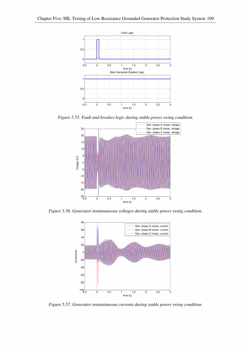
Chapter Five: HIL Testing of Low-Resistance Grounded Generator Protection Study System 109
Figure 5.55. Fault and breaker logic during stable power swing condition.
Figure 5.56. Generator instantaneous voltages during stable power swing condition.
Figure 5.57. Generator instantaneous currents during stable power swing condition.
-0.5 0 0.5 1 1.5 2 2.5 3
0
0.5
1
Fault Logic
time (s)
-0.5 0 0.5 1 1.5 2 2.5 3
0
0.5
1
Main Generator Breaker Logic
time (s)
-0.5 0 0.5 1 1.5 2 2.5 3-25
-20
-15
-10
-5
0
5
10
15
20
25
time (s)
Voltage (
kV
)
Gen. phase A instan. voltage
Gen. phase B instan. voltage
Gen. phase C instan. voltage
-0.5 0 0.5 1 1.5 2 2.5 3-100
-80
-60
-40
-20
0
20
40
60
80
time (s)
Curr
ent(
kA
)
Gen. phase A instan. current
Gen. phase B instan. current
Gen. phase C instan. current

Chapter Five: HIL Testing of Low-Resistance Grounded Generator Protection Study System 110
Figure 5.58. Active power output during stable power swing condition.
Figure 5.59. Reactive power output during stable power swing condition.
Figure 5.60. Generator terminal voltage during stable power swing condition.
-0.5 0 0.5 1 1.5 2 2.5 3-100
0
100
200
300
400
500
600
700
time (s)
Active P
ow
er
(MW
)
-0.5 0 0.5 1 1.5 2 2.5 3-200
-100
0
100
200
300
400
500
600
700
time (s)
Reactive P
ow
er
(MV
ar)
-0.5 0 0.5 1 1.5 2 2.5 30.3
0.4
0.5
0.6
0.7
0.8
0.9
1
1.1
time (s)
Vo
ltage (
pu)
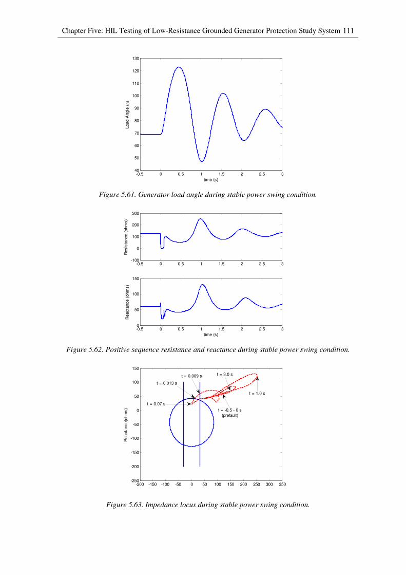
Chapter Five: HIL Testing of Low-Resistance Grounded Generator Protection Study System 111
Figure 5.61. Generator load angle during stable power swing condition.
Figure 5.62. Positive sequence resistance and reactance during stable power swing condition.
Figure 5.63. Impedance locus during stable power swing condition.
-0.5 0 0.5 1 1.5 2 2.5 340
50
60
70
80
90
100
110
120
130
time (s)
Load A
ngle
(δ)
-0.5 0 0.5 1 1.5 2 2.5 3-100
0
100
200
300
Resis
tance (
ohm
s)
-0.5 0 0.5 1 1.5 2 2.5 30
50
100
150
Reacta
nce (
ohm
s)
time (s)
-200 -150 -100 -50 0 50 100 150 200 250 300 350-250
-200
-150
-100
-50
0
50
100
150
Reacta
nce(o
hm
s)
t = 0.07 s
t = 0.013 s
t = 0.009 s t = 3.0 s
t = -0.5 - 0 s
(prefault)
t = 1.0 s
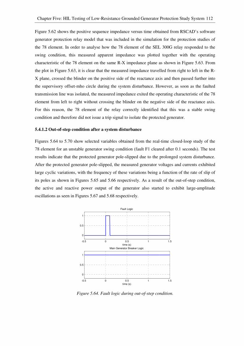
Chapter Five: HIL Testing of Low-Resistance Grounded Generator Protection Study System 112
Figure 5.62 shows the positive sequence impedance versus time obtained from RSCAD’s software
generator protection relay model that was included in the simulation for the protection studies of
the 78 element. In order to analyse how the 78 element of the SEL 300G relay responded to the
swing condition, this measured apparent impedance was plotted together with the operating
characteristic of the 78 element on the same R-X impedance plane as shown in Figure 5.63. From
the plot in Figure 5.63, it is clear that the measured impedance travelled from right to left in the R-
X plane, crossed the blinder on the positive side of the reactance axis and then passed further into
the supervisory offset-mho circle during the system disturbance. However, as soon as the faulted
transmission line was isolated, the measured impedance exited the operating characteristic of the 78
element from left to right without crossing the blinder on the negative side of the reactance axis.
For this reason, the 78 element of the relay correctly identified that this was a stable swing
condition and therefore did not issue a trip signal to isolate the protected generator.
5.4.1.2 Out-of-step condition after a system disturbance
Figures 5.64 to 5.70 show selected variables obtained from the real-time closed-loop study of the
78 element for an unstable generator swing condition (fault F1 cleared after 0.1 seconds). The test
results indicate that the protected generator pole-slipped due to the prolonged system disturbance.
After the protected generator pole-slipped, the measured generator voltages and currents exhibited
large cyclic variations, with the frequency of these variations being a function of the rate of slip of
its poles as shown in Figures 5.65 and 5.66 respectively. As a result of the out-of-step condition,
the active and reactive power output of the generator also started to exhibit large-amplitude
oscillations as seen in Figures 5.67 and 5.68 respectively.
Figure 5.64. Fault logic during out-of-step condition.
-0.5 0 0.5 1 1.5
0
0.5
1
Fault Logic
time (s)
-0.5 0 0.5 1 1.5
0
0.5
1
Main Generator Breaker Logic
time (s)
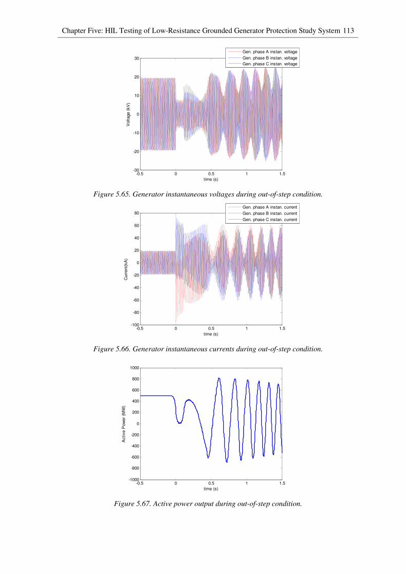
Chapter Five: HIL Testing of Low-Resistance Grounded Generator Protection Study System 113
Figure 5.65. Generator instantaneous voltages during out-of-step condition.
Figure 5.66. Generator instantaneous currents during out-of-step condition.
Figure 5.67. Active power output during out-of-step condition.
-0.5 0 0.5 1 1.5-30
-20
-10
0
10
20
30
time (s)
Voltage (
kV
)
Gen. phase A instan. voltage
Gen. phase B instan. voltage
Gen. phase C instan. voltage
-0.5 0 0.5 1 1.5-100
-80
-60
-40
-20
0
20
40
60
80
time (s)
Curr
ent(
kA
)
Gen. phase A instan. current
Gen. phase B instan. current
Gen. phase C instan. current
-0.5 0 0.5 1 1.5-1000
-800
-600
-400
-200
0
200
400
600
800
1000
time (s)
Active P
ow
er
(MW
)
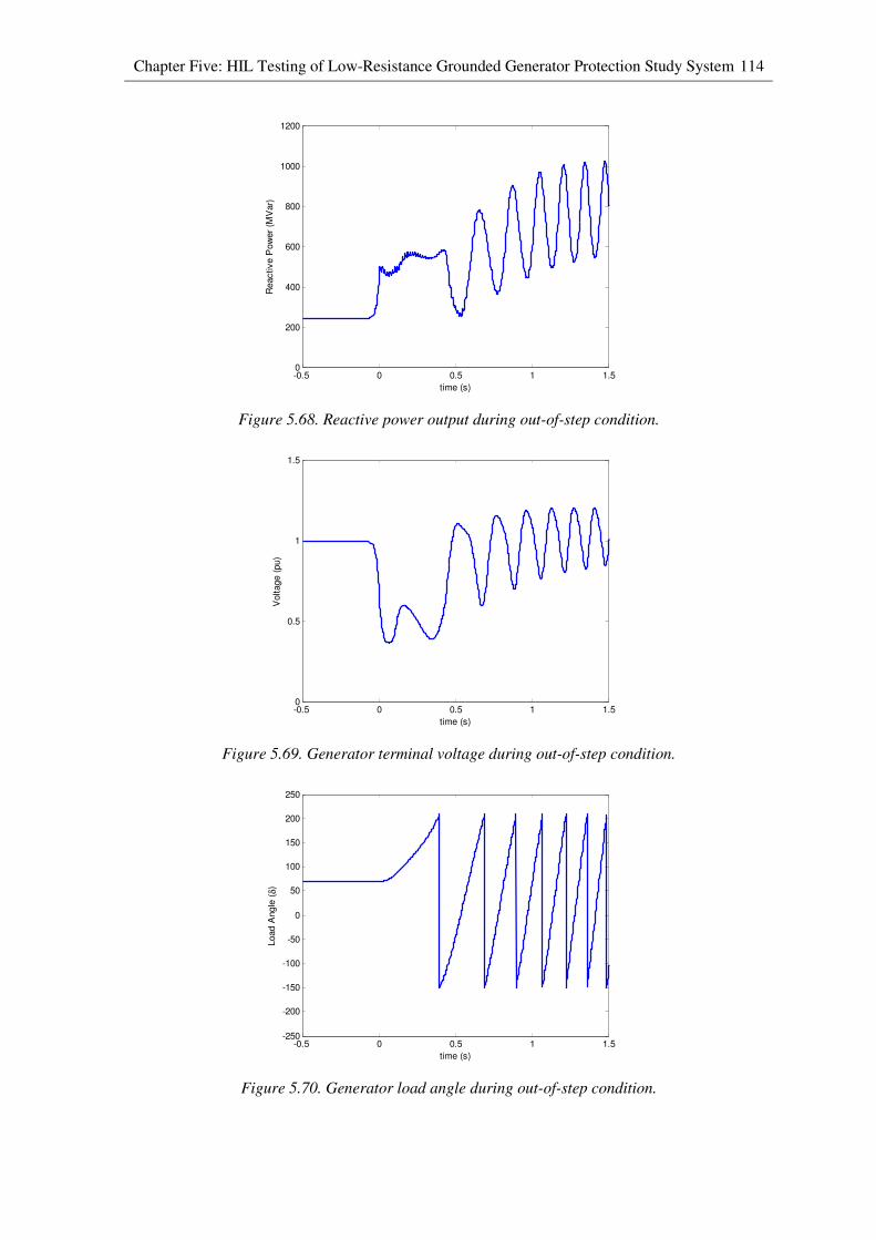
Chapter Five: HIL Testing of Low-Resistance Grounded Generator Protection Study System 114
Figure 5.68. Reactive power output during out-of-step condition.
Figure 5.69. Generator terminal voltage during out-of-step condition.
Figure 5.70. Generator load angle during out-of-step condition.
-0.5 0 0.5 1 1.50
200
400
600
800
1000
1200
time (s)
Reactive P
ow
er
(MV
ar)
-0.5 0 0.5 1 1.50
0.5
1
1.5
time (s)
Voltage (
pu)
-0.5 0 0.5 1 1.5-250
-200
-150
-100
-50
0
50
100
150
200
250
time (s)
Load A
ngle
(δ)
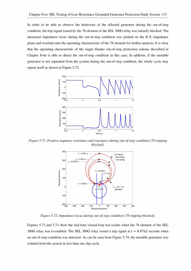
Chapter Five: HIL Testing of Low-Resistance Grounded Generator Protection Study System 115
In order to be able to observe the behaviour of the affected generator during the out-of-step
condition, the trip signal issued by the 78 element of the SEL 300G relay was initially blocked. The
measured impedance locus during the out-of-step condition was plotted on the R-X impedance
plane and overlaid onto the operating characteristic of the 78 element for further analysis. It is clear
that the operating characteristic of the single blinder out-of-step protection scheme described in
Chapter Four is able to detect the out-of-step condition in this case; In addition, if the unstable
generator is not separated from the system during the out-of-step condition, the whole cycle may
repeat itself as shown in Figure 5.72.
Figure 5.71. Positive sequence resistance and reactance during out-of-step condition (78 tripping
blocked).
Figure 5.72. Impedance locus during out-of-step condition (78 tripping blocked).
Figures 5.73 and 5.74 show the real-time closed-loop test results when the 78 element of the SEL
300G relay was re-enabled. The SEL 300G relay issued a trip signal at� = 0.4762 seconds when
an out-of-step condition was detected. As can be seen from Figure 5.74, the unstable generator was
isolated from the system in less than one slip cycle.
-0.5 0 0.5 1 1.5-200
-100
0
100
200
Resis
tance (
ohm
s)
-0.5 0 0.5 1 1.50
100
200
300
400
Reacta
nce (
ohm
s)
time (s)
-400 -300 -200 -100 0 100 200 300 400-200
-100
0
100
200
300
400
Resistance(ohms)
Reacta
nce(o
hm
s)
t = -0.5 - 0 s
(prefault)t = 0.07 s
t = 0.460 s
t = 1.0 s
t = 0.531 s
t = 0.7814 st = 0.9725 s
2nd swing
1st swing
3rd swing
t = 0.0125 s
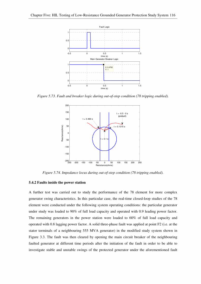
Chapter Five: HIL Testing of Low-Resistance Grounded Generator Protection Study System 116
Figure 5.73. Fault and breaker logic during out-of-step condition (78 tripping enabled).
Figure 5.74. Impedance locus during out-of-step condition (78 tripping enabled).
5.4.2 Faults inside the power station
A further test was carried out to study the performance of the 78 element for more complex
generator swing characteristics. In this particular case, the real-time closed-loop studies of the 78
element were conducted under the following system operating conditions: the particular generator
under study was loaded to 90% of full load capacity and operated with 0.9 leading power factor.
The remaining generators in the power station were loaded to 60% of full load capacity and
operated with 0.8 lagging power factor. A solid three-phase fault was applied at point F2 (i.e. at the
stator terminals of a neighbouring 555 MVA generator) in the modified study system shown in
Figure 3.3. The fault was then cleared by opening the main circuit breaker of the neighbouring
faulted generator at different time periods after the initiation of the fault in order to be able to
investigate stable and unstable swings of the protected generator under the aforementioned fault
-0.5 0 0.5 1 1.5
0
0.5
1
Fault Logic
time (s)
-0.5 0 0.5 1 1.5
0
0.5
1
X: 0.4762
Y: 1
Main Generator Breaker Logic
time (s)
-250 -200 -150 -100 -50 0 50 100 150 200 250-200
-150
-100
-50
0
50
100
150
200
Resistance(ohms)
Reacta
nce(o
hm
s)
t = 0.1 s
t = 0.1315 s
t = -0.5 - 0 s
(prefault)
t = 0.460 s

Chapter Five: HIL Testing of Low-Resistance Grounded Generator Protection Study System 117
scenario. The test results for a stable and an unstable case are presented in Sections 5.4.2.1 and
5.4.2.2.
5.4.2.1 Stable swing after a system disturbance
Figure 5.75 shows the measured impedance locus following the system disturbance, overlaid onto
both the loss-of-field and out-of-step operating characteristics in the R-X impedance plane, for a
stable case (fault F2 cleared at t=0.3 seconds). It is clear that the 78 element of the relay did not
issue a trip signal since the measured impedance did not pass into the supervisory offset-mho circle
even though it crossed blinders on both sides of the reactance axis. In addition, it was observed that
the measured impedance passed into the zone 2 mho characteristic of the loss-of-field protection
scheme (40) for 0.113 seconds during the post-fault recovery swing following the system
disturbance. In this case, the time delay of 0.5 seconds used with the zone 2 mho characteristic of
the 40 element (as discussed in Chapter Four) did prevent relay misoperation during the stable
recovery swing.
Figure 5.75. Impedance locus during stable power swing condition.
5.4.2.2 Out-of-step condition after a system disturbance
Figure 5.76 shows the measured impedance locus following the system disturbance, overlaid onto
the single-blinder out-of-step operating characteristics in the R-X impedance plane, for an unstable
case (fault F2 cleared at t = 0.7 seconds). As discussed in Chapter Four, if the ratio of the system
voltages is smaller than one ("g/"; o 1� during an out-of-step condition, the impedance locus will
be a circle with its centre located below the perpendicular bisector of the total system impedance
characteristic. The impedance locus seen in Figure 5.76 is an example of the aforementioned case.
-250 -200 -150 -100 -50 0 50 100 150 200 250 300-350
-300
-250
-200
-150
-100
-50
0
50
100
Resistance(ohms)
Reacta
nce(o
hm
s)
t = -0.2 - 0 s
(prefault)
t = 1.337 s
t = 1.407 s
t = 1.589 st = 0.3 s
t = 1.294 s
t = 1.279 s
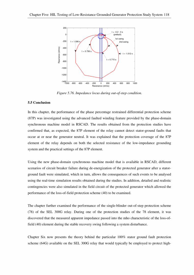
Chapter Five: HIL Testing of Low-Resistance Grounded Generator Protection Study System 118
Figure 5.76. Impedance locus during out-of-step condition.
5.5 Conclusion
In this chapter, the performance of the phase percentage restrained differential protection scheme
(87P) was investigated using the advanced faulted winding feature provided by the phase-domain
synchronous machine model in RSCAD. The results obtained from the protection studies have
confirmed that, as expected, the 87P element of the relay cannot detect stator-ground faults that
occur at or near the generator neutral. It was explained that the protection coverage of the 87P
element of the relay depends on both the selected resistance of the low-impedance grounding
system and the practical settings of the 87P element.
Using the new phase-domain synchronous machine model that is available in RSCAD, different
scenarios of circuit breaker failure during de-energization of the protected generator after a stator-
ground fault were simulated, which in turn, allows the consequences of such events to be analysed
using the real-time simulation results obtained during the studies. In addition, detailed and realistic
contingencies were also simulated in the field circuit of the protected generator which allowed the
performance of the loss-of-field protection scheme (40) to be examined.
The chapter further examined the performance of the single-blinder out-of-step protection scheme
(78) of the SEL 300G relay. During one of the protection studies of the 78 element, it was
discovered that the measured apparent impedance passed into the mho characteristic of the loss-of-
field (40) element during the stable recovery swing following a system disturbance.
Chapter Six now presents the theory behind the particular 100% stator ground fault protection
scheme (64G) available on the SEL 300G relay that would typically be employed to protect high-
-1000 -800 -600 -400 -200 0 200 400 600 800 1000-1400
-1200
-1000
-800
-600
-400
-200
0
200
Resistance (ohms)
Reacta
nce (
ohm
s)
t = -0.2 - 0 s
(prefault)
t = 1.012 s
t = 1.006 s
t = 0.715 s
t = 0.706 s
1st swing
2nd swing

Chapter Five: HIL Testing of Low-Resistance Grounded Generator Protection Study System 119
impedance grounded generators. The results of real-time simulator tests of the SEL 300G’s 64G
element are then presented in Chapter Seven.
CHAPTER 6
100% STATOR GROUND PROTECTION FOR HIGH-RESISTANCE
GROUNDED GENERATORS
6.1 Introduction
The previous chapter analysed the performance of specific generator protective functions employed
to protect a particular low-resistance grounded generator represented in the real-time simulation
model using the results obtained from real-time closed-loop studies of both hardware (SEL 300G)
and software (generic model) generator protection relays.
This chapter reviews the theory and design of an alternative generator grounding approach, namely
a high-resistance grounding scheme. Under this type of generator grounding scheme, the magnitude
of stator winding to ground (stator-ground) fault currents can be limited significantly. However,
due to the limited stator-ground fault currents, phase percentage restrained differential protection
(87P) can no longer detect phase-to-earth faults on the generator stator winding. For this reason,
alternative stator winding protection schemes for high-resistance grounded generators have been
proposed, namely 100% stator ground fault protection (64G) and neutral injection schemes (64S).
The chapter then further discusses the theory of operation and setting calculations for the 64G
element in particular, since it is the protection scheme available in the hardware generator
protection relay (SEL 300G) being considered in the thesis. It is important to note that one of the
64G’s sub-elements relies on measurements of the third-harmonic voltages in the generator stator
windings in order to make its tripping decisions. However, as discussed in Chapter Two, the
simplified version of the phase-domain synchronous machine model used in the work of this thesis
does not represent phase-belt harmonics in the generator stator windings, and therefore it is not able
to represent the third-harmonic voltages in these windings that are relied upon by one of the 64G’s
sub-elements to detect stator-ground faults. In order to examine the performance of the 64G
element of the SEL 300G generator protection relay using the real-time closed-loop approach, an
additional real-time simulation model had to be developed to supplement the characteristics of this
simplified machine model.
Finally, the chapter discusses the development of the additional real-time simulation model that
was used in the thesis to simulate the third-harmonic voltages produced in the generator stator
windings, which in turn, allows testing of 100% stator ground fault protection schemes that rely on
detection of third-harmonic voltages.
Chapter Six: 100% Stator Ground Protection for High-Resistance Grounded Generators 121
6.2 Review, theory and explanation of chosen method
There are two different approaches to implement high-resistance grounding schemes for generators.
One of the approaches is to install a resistor with high-ohmic value directly between generator
neutral and ground. Another approach is to utilize a single-phase distribution transformer as a
grounding transformer with its primary winding connected between generator neutral and ground,
while its secondary winding is loaded with a low-ohmic resistor [29]. Although both of the
aforementioned grounding approaches ultimately achieve the same outcome, the latter grounding
implementation is preferred in industry because of its rugged construction.
The purpose of implementing a high-resistance grounding scheme is to limit the maximum stator-
ground fault current considerably to a small magnitude, typically between 5 to 15 amperes in the
neutral path (depending on the chosen grounding resistor value) when a phase-to-earth fault occurs
at the generator terminals [29]. Under this type of grounding arrangement, the possibility of
causing severe physical damage to the generator during a stator-ground fault is greatly reduced due
to the limited stator-ground fault current. Although a stator-ground fault that occurs on a high-
resistance grounded generator does not pose as an immediate threat to either the power system’s
stability or to the generator itself, it is still highly recommended to remove the generator from
service as soon as the fault is detected rather than to delay this tripping action. The reason for
tripping immediately upon detection of a first stator-ground fault is to avoid the possibility of
extremely high fault currents that would flow if a second stator-ground fault were to occur in the
upper winding of the same phase [44],[45],[46].
In the past, a fundamental-frequency neutral overvoltage scheme (59GN) was employed to detect
stator-ground faults on high-resistance grounded generators. The 59GN element comprises an
overvoltage relay tuned to respond to the fundamental-frequency voltage measured across the
grounding resistor. Under non-faulted conditions, if all three phases of the generator’s stator
windings are perfectly balanced, there will be no fundamental-frequency current flowing in the
neutral path which results in zero fundamental-frequency voltage across the grounding resistor [46].
However, the fundamental-frequency voltage across the grounding resistor changes when a phase-
to-earth fault occurs on one of the phases of generator stator windings. The magnitude of the
fundamental-frequency voltage that appears across the grounding resistor is dependent on the
location of stator-ground fault. For instance, when a stator-ground fault occurs at the generator
terminals, the full-phase-to-neutral generator voltage at fundamental-frequency will appear across
the grounding resistor. As the location of the stator-ground fault moves toward the generator
neutral, the magnitude of the fundamental-frequency voltage that appears across the grounding
resistor becomes smaller and eventually reduces to zero for the case when the fault is located
Chapter Six: 100% Stator Ground Protection for High-Resistance Grounded Generators 122
exactly at the generator neutral. For this reason, the 59GN element is not able to detect stator-
ground faults that are located at or near the generator neutral. Nevertheless, the 59GN element does
still provide reliable protection for the upper 90% to 95% of the generator stator windings
depending on the sensitivity of the element [46].
Although the 59GN element is easy to implement and very reliable, there are two major
disadvantages associated with it. Firstly, the 59GN element does not have self-monitoring
capability and therefore it is not able to detect any contingencies on the grounding system (e.g.
short-circuit or open-circuit of grounding resistor) [44],[45]. If a stator-ground fault occurs when
the grounding resistor is short-circuited, the ground fault current is no longer limited by the high-
resistance grounding system and consequently it can result extremely high fault current. Under this
type of circumstance, the stator winding and stator core of the generator can be subjected to
substantial damage. The second disadvantage of the 59GN element is the inability to detect stator-
ground faults that are located at or near generator neutral due to insufficient sensitivity of the
element. In the past, a small percentage of unprotected generator stator windings near the neutral
end did not raise significant concern since it was considered unlikely to have a ground fault in this
region due to low insulation stress [45]. However, one of Georgia Power Company’s generator
units was severely damaged due to the inability of a 59GN element to detect a turn-to-turn fault
that occurred near the generator neutral. Due to the arcing nature of the original fault, an adjacent
coil was damaged and consequently caused the original fault to evolve into a phase-to-phase fault
that caused substantial current to flow in the stator windings [45]. Although it is important to
provide protection for the upper 90% to 95% of generator stator windings, evidence suggests that it
is equally important to provide protection for generator stator windings near the generator neutral.
Over the years, different types of protection scheme have been proposed to supplement the
protection-blind region of the 59GN element. These protection schemes utilize a distinct practical
characteristic of generators in order to detect the presence of stator-ground faults near the generator
neutral, namely the non-sinusoidal components in their output voltages: generators typically
produce harmonic voltages such as the 3rd
, 9th and 15
th harmonic [32]. Of these harmonic voltages,
the 3rd
harmonic voltage has the highest magnitude and it is the one chosen for use in the following
generator protection schemes, namely third-harmonic undervoltage scheme (27H), third-harmonic
overvoltage scheme (59T) and third-harmonic voltage differential scheme (59D). Before discussing
the theory of operation of the aforementioned protection schemes, one needs to understand the
distribution of third-harmonic voltages within generator stator windings under healthy and faulted
generator operating conditions.
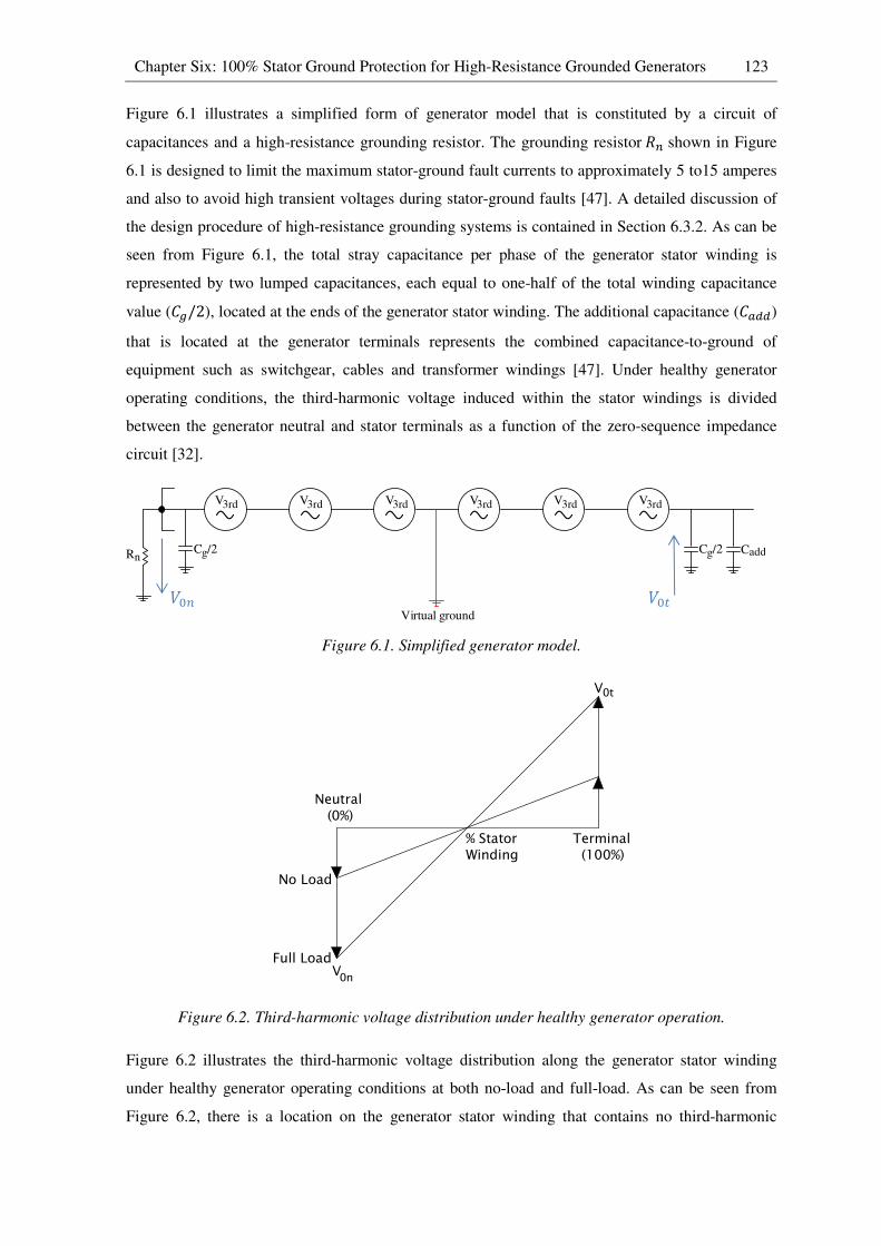
Chapter Six: 100% Stator Ground Protection for High-Resistance Grounded Generators 123
Figure 6.1 illustrates a simplified form of generator model that is constituted by a circuit of
capacitances and a high-resistance grounding resistor. The grounding resistorTZ shown in Figure
6.1 is designed to limit the maximum stator-ground fault currents to approximately 5 to15 amperes
and also to avoid high transient voltages during stator-ground faults [47]. A detailed discussion of
the design procedure of high-resistance grounding systems is contained in Section 6.3.2. As can be
seen from Figure 6.1, the total stray capacitance per phase of the generator stator winding is
represented by two lumped capacitances, each equal to one-half of the total winding capacitance
value (Hg/2), located at the ends of the generator stator winding. The additional capacitance (H���)
that is located at the generator terminals represents the combined capacitance-to-ground of
equipment such as switchgear, cables and transformer windings [47]. Under healthy generator
operating conditions, the third-harmonic voltage induced within the stator windings is divided
between the generator neutral and stator terminals as a function of the zero-sequence impedance
circuit [32].
Figure 6.1. Simplified generator model.
Figure 6.2. Third-harmonic voltage distribution under healthy generator operation.
Figure 6.2 illustrates the third-harmonic voltage distribution along the generator stator winding
under healthy generator operating conditions at both no-load and full-load. As can be seen from
Figure 6.2, there is a location on the generator stator winding that contains no third-harmonic
% Stator Winding
Neutral (0%)
Terminal (100%)
V
No Load
VFull Load
0n
0t
*�6 *�Z
V3rd V3rd V3rd V3rd V3rd V3rd
RnCg/2 Cg/2 Cadd
Virtual ground
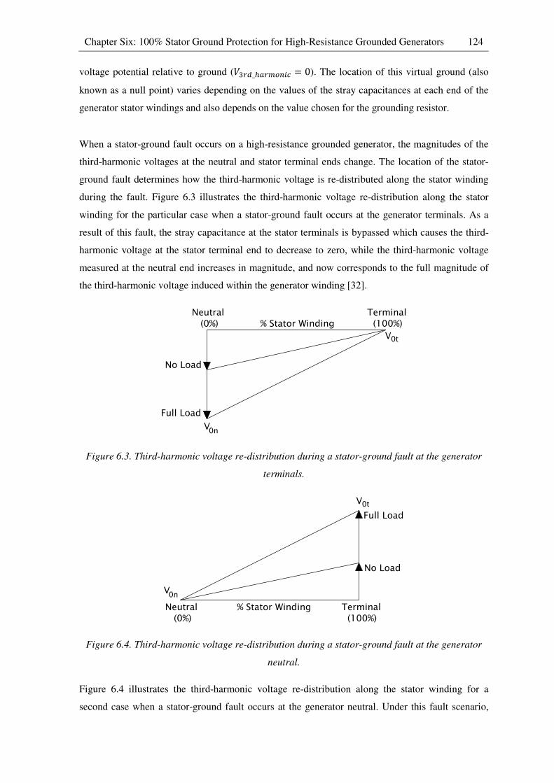
Chapter Six: 100% Stator Ground Protection for High-Resistance Grounded Generators 124
voltage potential relative to ground (*G[�_3�[�Z]� = 0). The location of this virtual ground (also
known as a null point) varies depending on the values of the stray capacitances at each end of the
generator stator windings and also depends on the value chosen for the grounding resistor.
When a stator-ground fault occurs on a high-resistance grounded generator, the magnitudes of the
third-harmonic voltages at the neutral and stator terminal ends change. The location of the stator-
ground fault determines how the third-harmonic voltage is re-distributed along the stator winding
during the fault. Figure 6.3 illustrates the third-harmonic voltage re-distribution along the stator
winding for the particular case when a stator-ground fault occurs at the generator terminals. As a
result of this fault, the stray capacitance at the stator terminals is bypassed which causes the third-
harmonic voltage at the stator terminal end to decrease to zero, while the third-harmonic voltage
measured at the neutral end increases in magnitude, and now corresponds to the full magnitude of
the third-harmonic voltage induced within the generator winding [32].
Figure 6.3. Third-harmonic voltage re-distribution during a stator-ground fault at the generator
terminals.
Figure 6.4. Third-harmonic voltage re-distribution during a stator-ground fault at the generator
neutral.
Figure 6.4 illustrates the third-harmonic voltage re-distribution along the stator winding for a
second case when a stator-ground fault occurs at the generator neutral. Under this fault scenario,
% Stator WindingNeutral (0%)
Terminal (100%)
V
V0n
0t
No Load
Full Load
% Stator WindingNeutral (0%)
Terminal (100%)
V
V0n
0t
No Load
Full Load
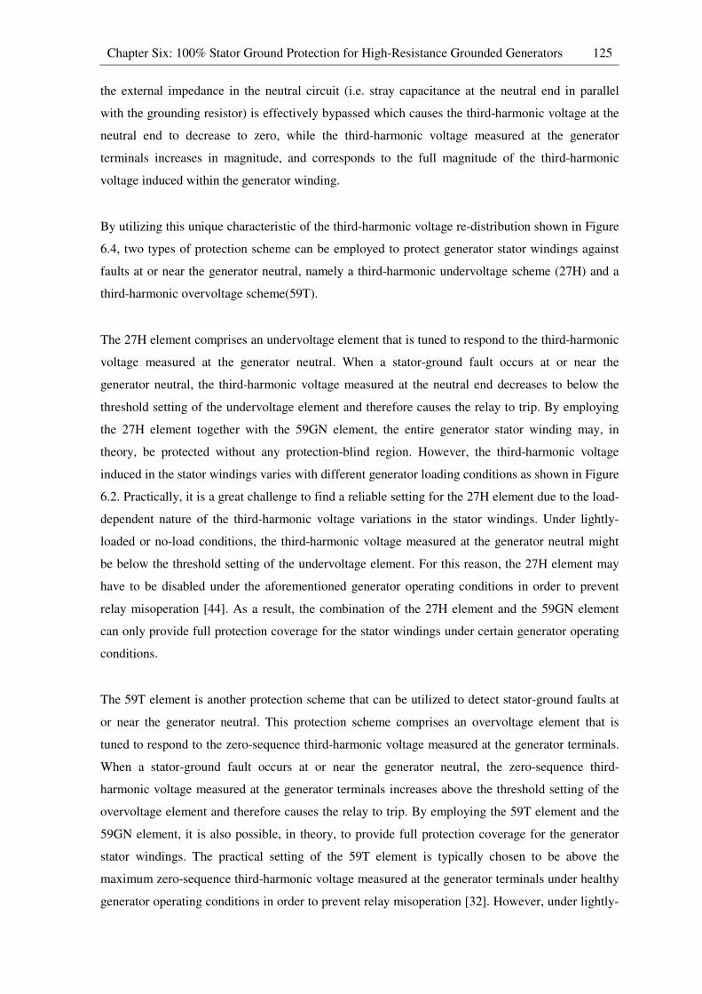
Chapter Six: 100% Stator Ground Protection for High-Resistance Grounded Generators 125
the external impedance in the neutral circuit (i.e. stray capacitance at the neutral end in parallel
with the grounding resistor) is effectively bypassed which causes the third-harmonic voltage at the
neutral end to decrease to zero, while the third-harmonic voltage measured at the generator
terminals increases in magnitude, and corresponds to the full magnitude of the third-harmonic
voltage induced within the generator winding.
By utilizing this unique characteristic of the third-harmonic voltage re-distribution shown in Figure
6.4, two types of protection scheme can be employed to protect generator stator windings against
faults at or near the generator neutral, namely a third-harmonic undervoltage scheme (27H) and a
third-harmonic overvoltage scheme(59T).
The 27H element comprises an undervoltage element that is tuned to respond to the third-harmonic
voltage measured at the generator neutral. When a stator-ground fault occurs at or near the
generator neutral, the third-harmonic voltage measured at the neutral end decreases to below the
threshold setting of the undervoltage element and therefore causes the relay to trip. By employing
the 27H element together with the 59GN element, the entire generator stator winding may, in
theory, be protected without any protection-blind region. However, the third-harmonic voltage
induced in the stator windings varies with different generator loading conditions as shown in Figure
6.2. Practically, it is a great challenge to find a reliable setting for the 27H element due to the load-
dependent nature of the third-harmonic voltage variations in the stator windings. Under lightly-
loaded or no-load conditions, the third-harmonic voltage measured at the generator neutral might
be below the threshold setting of the undervoltage element. For this reason, the 27H element may
have to be disabled under the aforementioned generator operating conditions in order to prevent
relay misoperation [44]. As a result, the combination of the 27H element and the 59GN element
can only provide full protection coverage for the stator windings under certain generator operating
conditions.
The 59T element is another protection scheme that can be utilized to detect stator-ground faults at
or near the generator neutral. This protection scheme comprises an overvoltage element that is
tuned to respond to the zero-sequence third-harmonic voltage measured at the generator terminals.
When a stator-ground fault occurs at or near the generator neutral, the zero-sequence third-
harmonic voltage measured at the generator terminals increases above the threshold setting of the
overvoltage element and therefore causes the relay to trip. By employing the 59T element and the
59GN element, it is also possible, in theory, to provide full protection coverage for the generator
stator windings. The practical setting of the 59T element is typically chosen to be above the
maximum zero-sequence third-harmonic voltage measured at the generator terminals under healthy
generator operating conditions in order to prevent relay misoperation [32]. However, under lightly-
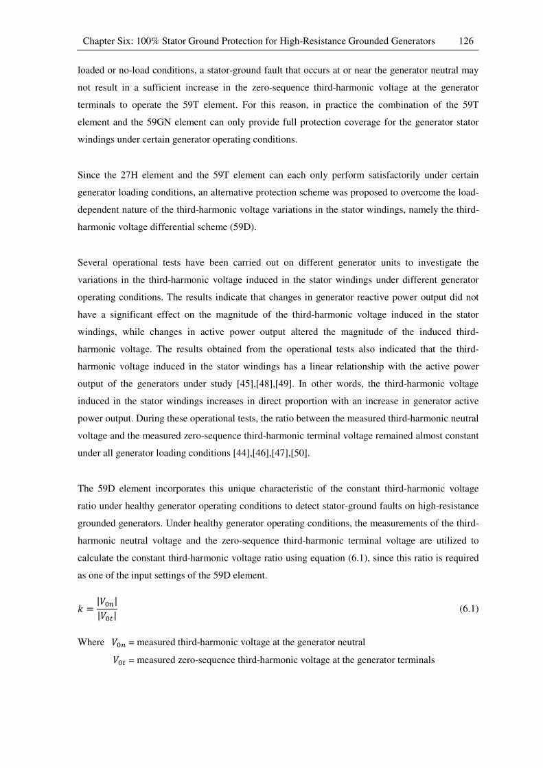
Chapter Six: 100% Stator Ground Protection for High-Resistance Grounded Generators 126
loaded or no-load conditions, a stator-ground fault that occurs at or near the generator neutral may
not result in a sufficient increase in the zero-sequence third-harmonic voltage at the generator
terminals to operate the 59T element. For this reason, in practice the combination of the 59T
element and the 59GN element can only provide full protection coverage for the generator stator
windings under certain generator operating conditions.
Since the 27H element and the 59T element can each only perform satisfactorily under certain
generator loading conditions, an alternative protection scheme was proposed to overcome the load-
dependent nature of the third-harmonic voltage variations in the stator windings, namely the third-
harmonic voltage differential scheme (59D).
Several operational tests have been carried out on different generator units to investigate the
variations in the third-harmonic voltage induced in the stator windings under different generator
operating conditions. The results indicate that changes in generator reactive power output did not
have a significant effect on the magnitude of the third-harmonic voltage induced in the stator
windings, while changes in active power output altered the magnitude of the induced third-
harmonic voltage. The results obtained from the operational tests also indicated that the third-
harmonic voltage induced in the stator windings has a linear relationship with the active power
output of the generators under study [45],[48],[49]. In other words, the third-harmonic voltage
induced in the stator windings increases in direct proportion with an increase in generator active
power output. During these operational tests, the ratio between the measured third-harmonic neutral
voltage and the measured zero-sequence third-harmonic terminal voltage remained almost constant
under all generator loading conditions [44],[46],[47],[50].
The 59D element incorporates this unique characteristic of the constant third-harmonic voltage
ratio under healthy generator operating conditions to detect stator-ground faults on high-resistance
grounded generators. Under healthy generator operating conditions, the measurements of the third-
harmonic neutral voltage and the zero-sequence third-harmonic terminal voltage are utilized to
calculate the constant third-harmonic voltage ratio using equation (6.1), since this ratio is required
as one of the input settings of the 59D element.
1 = |*�Z||*�6| (6.1)
Where *�Z = measured third-harmonic voltage at the generator neutral
*�6 = measured zero-sequence third-harmonic voltage at the generator terminals

Chapter Six: 100% Stator Ground Protection for High-Resistance Grounded Generators 127
By rearranging equation (6.1), equation (6.2) can be derived as follows.
1 × |*�6| − |*�Z| = 0 (6.2)
Ideally, under un-faulted conditions, the differential voltage calculated from the measurements of
the third-harmonic neutral voltage and the zero-sequence third-harmonic terminal voltage would be
zero under all generator loading conditions as shown in equation (6.2). However, the situation
described above is somewhat idealized. In practice, it is possible to have slight variations in the
third-harmonic voltage ratio under different generator loading conditions. For this reason, an
operating margin*;,6 shown in equation (6.3) is introduced in the 59D element in order to increase
the security of the protection scheme and therefore to prevent misoperation under healthy generator
operating conditions.
*;,6 = 1 × |*�6| − |*�Z| (6.3)
Where*;,6 = setting of the operating margin of the 59D element
1 = constant third-harmonic voltage ratio under healthy generator operations
In general, if a stator-ground fault occurs on a high-resistance grounded generator, the ratio
between the measured third-harmonic neutral voltage and the zero-sequence third-harmonic
terminal voltage changes. The algorithm of the 59D element shows that if the differential voltage
calculated from the measurements of the third-harmonic voltage exceeds the operating margin*;,6 under faulted generator conditions, the relay will operate and remove the faulted generator from
service. However, it is important to note that the 59D element alone cannot provide full protection
for the stator windings of high-resistance grounded generators since there will always be a lack of
coverage over some internal portion of the winding. For instance, if a phase-to-earth fault occurs at
or near the point where the third-harmonic voltage distribution along the stator winding crosses
through zero as shown in Figure 6.2, the changes in the third-harmonic voltage ratio at the
generator neutral and stator terminal ends will be insignificant. As a result, the differential voltage
calculated from the measurements of the third-harmonic neutral voltage and zero-sequence third-
harmonic terminal voltage is insufficient to operate the 59D element for such faults. For this reason,
a 59D element is typically employed together with a 59GN element in order to provide full
protection coverage of the generator stator windings since their respective protection-blind regions
are located in different parts of the winding. In the SEL 300G generator protection relay, the 100%
stator ground fault protection scheme (64G) that is typically employed to protect high-resistance
grounded generators comprises a 59GN element and a 59D element. However, since both the
59GN element and the 59D element are considered sub-elements of the 64G element in the 300G
relay, their device function numbers have been changed to 64G1 and 64G2 respectively in the
Chapter Six: 100% Stator Ground Protection for High-Resistance Grounded Generators 128
manufacturer’s literature. The terms 64G1 and 64G2 are therefore used from this point on in the
thesis to refer to these sub-elements.
It is important to note that the magnitude of the third-harmonic voltage induced within generator
stator windings can vary considerably from one generator to another since these voltages are
produced as a result of winding space harmonics and are therefore dependent on the machine’s
physical design. For this reason, operational tests must be carried out on the generator units in order
to understand the characteristics of the induced third-harmonic voltages for each individual
generator unit to be protected. In order to perform satisfactorily, the 64G2 element requires that the
minimum magnitude of the third-harmonic voltage induced in the stator windings be 1% of the
nominal generator voltage [47]. If the induced third-harmonic voltage is below 1% of the nominal
generator voltage due to the machine’s physical design, or if the third-harmonic voltage ratio varies
dramatically under different generator loading conditions so that a secure operating margin*;,6 cannot be found, the 64G2 element is no longer suitable for protecting high-resistance grounded
generators. In such cases, an alternative protection method, such as a neutral injection scheme
(64S), can be considered.
6.3 Real-time modelling for 100% stator ground fault protection testing
In order to study the performance of the 100% stator ground fault protection scheme (64G) of the
SEL 300G generator protection relay using the real-time closed-loop testing approach, a realistic
RSCAD representation of the study system was required. As discussed in Chapter Three, the study
system shown in Figure 3.1 was modified using a slightly different approach to lumping the
multiple generators in the power station as shown in Figure 3.2 which, in turn, allows the SEL
300G relay connected to the real-time simulator in a hardware-in-loop configuration to protect one
of the four generator units in the station. In addition, all four generator units were grounded through
a high-resistance grounding system. With this modified study system, generator internal winding
faults can be considered on the particular high-resistance grounded 555 MVA generator under
study which allows the performance of the 64G element to be examined. The following sections
describe the particular details that were required in the development and parameterisation of the
real-time simulation model which was used for the protection studies of the 64G element. Section
6.3.1 reviews the choice of the system parameters (i.e. stray capacitances of the stator windings and
auxiliary equipment) to be represented in the real-time simulation model. Section 6.3.2
demonstrates the design procedure of the practical high-resistance grounding approach described in
[45]. Finally, Section 6.3.3 discusses the additional real-time model that was developed to simulate
the third-harmonic voltages induced in the stator windings in order to supplement the
characteristics of the simplified phase-domain synchronous machine model.
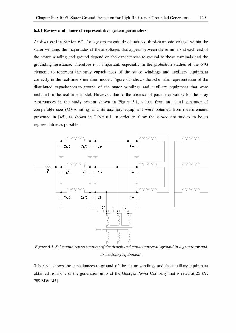
Chapter Six: 100% Stator Ground Protection for High-Resistance Grounded Generators 129
6.3.1 Review and choice of representative system parameters
As discussed in Section 6.2, for a given magnitude of induced third-harmonic voltage within the
stator winding, the magnitudes of these voltages that appear between the terminals at each end of
the stator winding and ground depend on the capacitances-to-ground at these terminals and the
grounding resistance. Therefore it is important, especially in the protection studies of the 64G
element, to represent the stray capacitances of the stator windings and auxiliary equipment
correctly in the real-time simulation model. Figure 6.5 shows the schematic representation of the
distributed capacitances-to-ground of the stator windings and auxiliary equipment that were
included in the real-time model. However, due to the absence of parameter values for the stray
capacitances in the study system shown in Figure 3.1, values from an actual generator of
comparable size (MVA rating) and its auxiliary equipment were obtained from measurements
presented in [45], as shown in Table 6.1, in order to allow the subsequent studies to be as
representative as possible.
Figure 6.5. Schematic representation of the distributed capacitances-to-ground in a generator and
its auxiliary equipment.
Table 6.1 shows the capacitances-to-ground of the stator windings and the auxiliary equipment
obtained from one of the generation units of the Georgia Power Company that is rated at 25 kV,
789 MW [45].

Chapter Six: 100% Stator Ground Protection for High-Resistance Grounded Generators 130
Table 6.1. List of equipment in the diagram of Figure 6.5 with their capacitances-to-ground [45]
Equipment Capacitance (|p)
Generator winding capacitance to ground per phase (Hg� 0.224
Lead capacitance to ground per phase (H8� 0.002
GSU transformer capacitance to ground per phase (H}� 0.020
Unit Auxiliary transformer phase-to-ground capacitance (H�� 0.008
Total capacitance per phase (Hg_66�~/�3�;,) 0.254
Total capacitance for three phase (Hg_66�~) 0.762
6.3.2 Practical design of representative grounding system parameters
As discussed in Section 6.2, there are two approaches to implement high-resistance grounding
schemes for generators. In this section, the high-resistance grounding system that was designed and
included in the neutral circuit of the particular 555 MVA generator under study comprises a single-
phase distribution transformer used as a grounding transformer with its primary winding connected
between the generator neutral and ground, and with its secondary winding loaded with a low-ohmic
resistor. The design and ratings of the equipment in this grounding system were determined by
closely following the guideline described in [29] in order to make the parameters of the grounding
system as representative as possible. As explained earlier, the grounding resistance is selected to
limit the maximum ground fault currents to between 5 to 15 amperes and also to prevent high
transient voltages during stator-ground faults. In order to meet the aforementioned criteria when
selecting the grounding resistance, the guideline shown in equation (6.4) was followed. The
guideline states [29] that the selected grounding resistance must be less than or equal to the ohmic
value of the total three-phase capacitance-to-ground. In other words, the ratio of the ohmic value of
the total three-phase capacitance-to-ground (`��_�����) over the grounding resistance (TZ) must be
greater than or equal to one.
`��_�����/TZ ≥ 1 (6.4)
As mentioned in Section 6.3.1, the actual values of stray capacitance shown in Table 6.1 were
included in the real-time simulation model. Following the guideline shown in equation (6.4), the
grounding resistance can be determined as follows.
The first step is to calculate the ohmic value of the total three-phase capacitance-to-ground at
system frequency (which, in the case of the chosen study system, is 60 Hz).
`��_����� = 1� ∙ Hg_66�~
= 1(2' ∗ 60� ∗ (0.762 ∗ 10�F� = 3481.08Ω
Chapter Six: 100% Stator Ground Protection for High-Resistance Grounded Generators 131
The highest recommended grounding resistance can then be found by setting the ratio (`��_�����/TZ) equal to one.
T�[]��[\ = `��_����� = 3481.08Ω
If the grounding approach is to connect a grounding resistor directly between the generator neutral
and ground, the grounding resistance calculated above (T�[]��[\) can be selected. However, a
single-phase grounding transformer was used in this grounding scheme and therefore the calculated
grounding resistance (T�[]��[\ ) was referred to the secondary side of the transformer. The
grounding transformer that was included in the neutral circuit of the particular generator under
study has turns ratio of 14400:240, based on the nearest standard voltage on the primary winding
above the generator nominal phase to neutral voltage.
T;,�Z��[\ = T�[]��[\/ u *�[]��[\*;,�Z��[\v�
= 3481.08/ l14400240 m� = 0.97Ω
Under this grounding system, the maximum stator-ground fault current that flows through the
primary winding of the grounding transformer can be calculated as follows.
7�[]��[\ = "�[]��[\T;,�Z��[\ ∗ l *�[]��[\*;,�Z��[\m
�
= 24/√3 ∗ 10G0.97 ∗ �14400240 ��
= 3.97D
Where "�[]��[\ = rated nominal generator voltage per phase (This is the maximum voltage that
can appear across the primary winding of the grounding transformer during stator-ground faults.)
From the above calculation, the maximum stator-ground fault current that flows through the
secondary winding of the grounding transformer can be calculated using the turns ratio of the
transformer.
7;,�Z��[\ = 7�[]��[\ ∗ u *�[]��[\*;,�Z��[\v
= 3.97 ∗ l14400240 m = 233.2D
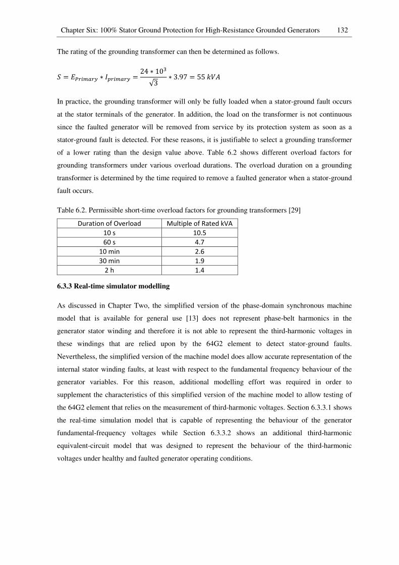
Chapter Six: 100% Stator Ground Protection for High-Resistance Grounded Generators 132
The rating of the grounding transformer can then be determined as follows.
C = "�[]��[\ ∗ 7�[]��[\ = 24 ∗ 10G√3 ∗ 3.97 = 551*D
In practice, the grounding transformer will only be fully loaded when a stator-ground fault occurs
at the stator terminals of the generator. In addition, the load on the transformer is not continuous
since the faulted generator will be removed from service by its protection system as soon as a
stator-ground fault is detected. For these reasons, it is justifiable to select a grounding transformer
of a lower rating than the design value above. Table 6.2 shows different overload factors for
grounding transformers under various overload durations. The overload duration on a grounding
transformer is determined by the time required to remove a faulted generator when a stator-ground
fault occurs.
Table 6.2. Permissible short-time overload factors for grounding transformers [29]
Duration of Overload Multiple of Rated kVA
10 s 10.5
60 s 4.7
10 min 2.6
30 min 1.9
2 h 1.4
6.3.3 Real-time simulator modelling
As discussed in Chapter Two, the simplified version of the phase-domain synchronous machine
model that is available for general use [13] does not represent phase-belt harmonics in the
generator stator winding and therefore it is not able to represent the third-harmonic voltages in
these windings that are relied upon by the 64G2 element to detect stator-ground faults.
Nevertheless, the simplified version of the machine model does allow accurate representation of the
internal stator winding faults, at least with respect to the fundamental frequency behaviour of the
generator variables. For this reason, additional modelling effort was required in order to
supplement the characteristics of this simplified version of the machine model to allow testing of
the 64G2 element that relies on the measurement of third-harmonic voltages. Section 6.3.3.1 shows
the real-time simulation model that is capable of representing the behaviour of the generator
fundamental-frequency voltages while Section 6.3.3.2 shows an additional third-harmonic
equivalent-circuit model that was designed to represent the behaviour of the third-harmonic
voltages under healthy and faulted generator operating conditions.
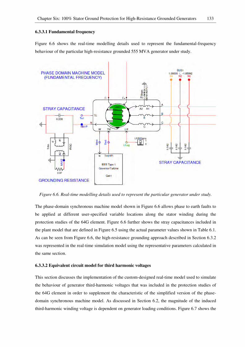
Chapter Six: 100% Stator Ground Protection for High-Resistance Grounded Generators 133
6.3.3.1 Fundamental frequency
Figure 6.6 shows the real-time modelling details used to represent the fundamental-frequency
behaviour of the particular high-resistance grounded 555 MVA generator under study.
Figure 6.6. Real-time modelling details used to represent the particular generator under study.
The phase-domain synchronous machine model shown in Figure 6.6 allows phase to earth faults to
be applied at different user-specified variable locations along the stator winding during the
protection studies of the 64G element. Figure 6.6 further shows the stray capacitances included in
the plant model that are defined in Figure 6.5 using the actual parameter values shown in Table 6.1.
As can be seen from Figure 6.6, the high-resistance grounding approach described in Section 6.3.2
was represented in the real-time simulation model using the representative parameters calculated in
the same section.
6.3.3.2 Equivalent circuit model for third harmonic voltages
This section discusses the implementation of the custom-designed real-time model used to simulate
the behaviour of generator third-harmonic voltages that was included in the protection studies of
the 64G element in order to supplement the characteristic of the simplified version of the phase-
domain synchronous machine model. As discussed in Section 6.2, the magnitude of the induced
third-harmonic winding voltage is dependent on generator loading conditions. Figure 6.7 shows the

Chapter Six: 100% Stator Ground Protection for High-Resistance Grounded Generators 134
design of real-time modelling elements that can be adapted to represent the known load-dependent
characteristics of any generator’s third-harmonic winding voltages. However, the coefficients of
the model were configured in order to replicate the specific characteristics of the actual third-
harmonic winding voltages of a comparably-rated large synchronous generator (Lambton generator
unit No. 4, in Ontario Hydro’s system, that is rated at 24kV, 500 MW [49]) for the particular
studies carried out in this thesis. The specific characteristics of the aforementioned synchronous
generator obtained from the operational testing results presented in [49] indicate that the induced
third-harmonic winding voltage varies in the range from 2% to 9% of the generator’s nominal
phase-to-neutral voltage from no-load to full-load. The induced third-harmonic winding voltages
were represented using voltage sources in each phase of the equivalent circuit representation shown
in Figure 6.8 and the magnitude of which are dynamically adjusted by the model elements shown
in Figure 6.7 based on any changes in generator loading conditions. The relative magnitude of the
generated third-harmonic voltage sources on either side of the fault component in the equivalent
circuit representation in Figure 6.8 are also adjusted according to the user-selected fault location
chosen within the main, phase-domain synchronous generator model used to represent the
fundamental frequency characteristics of the faulted generator (of Figure 6.6). By using the
equivalent circuit model shown in Figure 6.8, the behaviour of the third-harmonic voltages at the
neutral and stator terminals of the generator can therefore be represented under both healthy and
faulted generator operating conditions.
Figure 6.7. Modelling elements for representing the load-dependent characteristics of the
generator’s third-harmonic winding voltages in the equivalent circuit model.

Chapter Six: 100% Stator Ground Protection for High-Resistance Grounded Generators 135
Figure 6.8. Equivalent circuit model for induced third harmonic voltages.
Finally, the fundamental-frequency voltages and the third-harmonic voltages measured at the
neutral and stator terminals of the particular high-resistance grounded generator under study are
combined within the real-time simulation model using the superposition principle. These composite
voltage signals representing the fundamental and third-harmonic voltages measured at both ends of
the generator stator winding are then exported to the SEL 300G generator protection relay under
test in order for the 64G element to make tripping decisions (refer to Figure A.19 in Appendix A
for further details).
6.3.3.3 Hardware-in-loop (HIL) connection
By using the same hardware-in-loop connection of the SEL 300G generator protection relay with
the real-time simulation model described in Chapter Three, various protection studies were carried
out in order to examine the performance of the relay’s 64G element. As discussed in Section 6.2,
the 64G element requires voltage measurements at the neutral and stator terminals of the particular
high-resistance grounded 555 MVA generator under study in order to make tripping decisions. For
this reason, two voltage transformers are included within the real-time simulation model in order to
measure voltages at the neutral and stator terminals of the protected generator, and their secondary
quantities are then injected into the normal measurement inputs of the SEL 300G relay under test.
Since the measurements obtained from the voltage transformers are composite voltage signals
which contain both fundamental-frequency and third-harmonic voltages, the SEL 300G relay
performs a discrete Fourier transform (DFT) on the input voltage measurements in order to filter
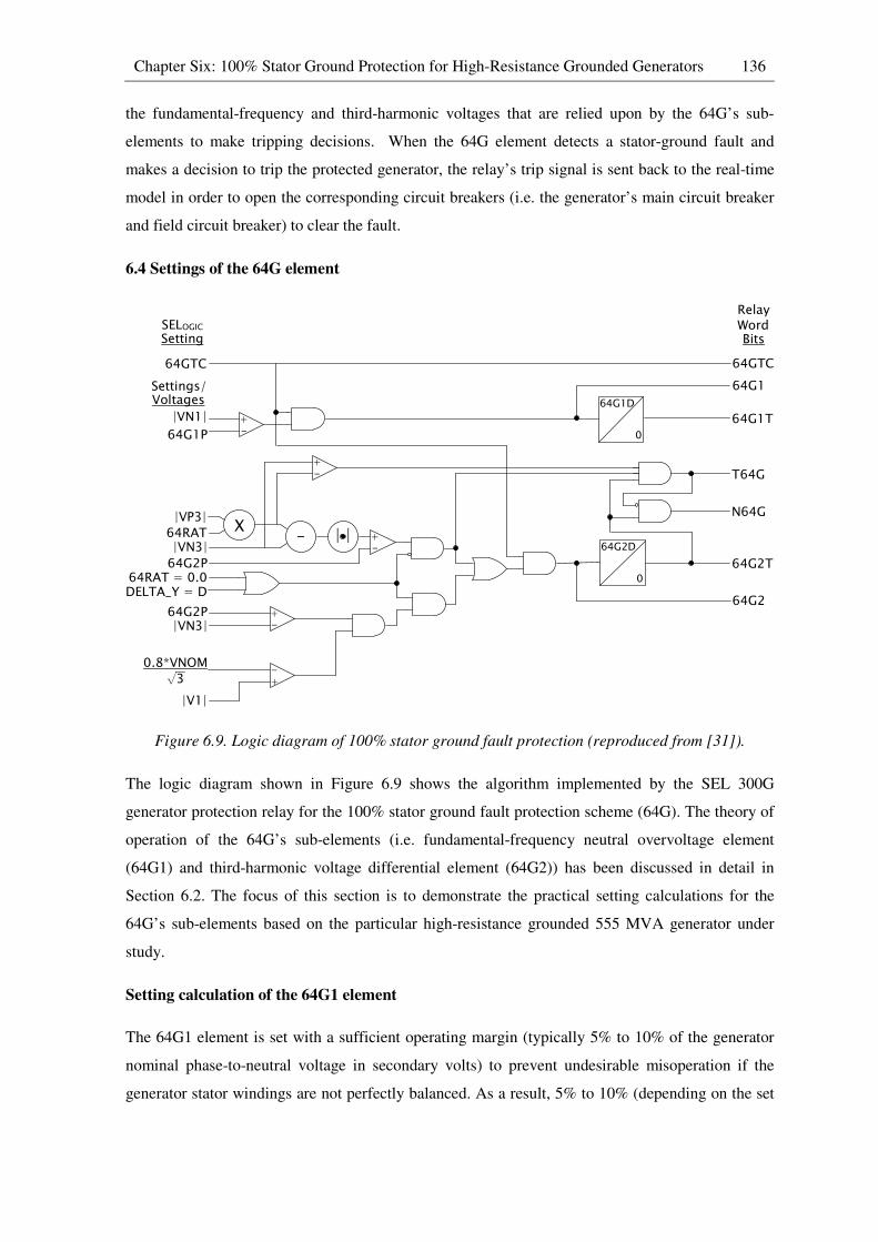
Chapter Six: 100% Stator Ground Protection for High-Resistance Grounded Generators 136
the fundamental-frequency and third-harmonic voltages that are relied upon by the 64G’s sub-
elements to make tripping decisions. When the 64G element detects a stator-ground fault and
makes a decision to trip the protected generator, the relay’s trip signal is sent back to the real-time
model in order to open the corresponding circuit breakers (i.e. the generator’s main circuit breaker
and field circuit breaker) to clear the fault.
6.4 Settings of the 64G element
Figure 6.9. Logic diagram of 100% stator ground fault protection (reproduced from [31]).
The logic diagram shown in Figure 6.9 shows the algorithm implemented by the SEL 300G
generator protection relay for the 100% stator ground fault protection scheme (64G). The theory of
operation of the 64G’s sub-elements (i.e. fundamental-frequency neutral overvoltage element
(64G1) and third-harmonic voltage differential element (64G2)) has been discussed in detail in
Section 6.2. The focus of this section is to demonstrate the practical setting calculations for the
64G’s sub-elements based on the particular high-resistance grounded 555 MVA generator under
study.
Setting calculation of the 64G1 element
The 64G1 element is set with a sufficient operating margin (typically 5% to 10% of the generator
nominal phase-to-neutral voltage in secondary volts) to prevent undesirable misoperation if the
generator stator windings are not perfectly balanced. As a result, 5% to 10% (depending on the set
+-
Setting
64GTC
64G1P
SELOGIC
Settings/Voltages
|VN1|
|VP3|64RAT|VN3|64G2P
64RAT = 0.0DELTA_Y = D
64G2P|VN3|
0.8*VNOM√3
|V1|
+-
+-
+-
+-
64G2D
0
Relay WordBits
64GTC
64G1
64G1T
T64G
N64G
64G2T
64G2
64G1D
0
X- | |

Chapter Six: 100% Stator Ground Protection for High-Resistance Grounded Generators 137
operating margin) of the stator winding closest to the neutral end is not protected by the 64G1
element due to the insufficient sensitivity of the element.
In this study, the operating margin was set at 5% of the generator nominal phase-to-neutral voltage
in secondary volts. The threshold setting of the 64G1 element (64G1P) was then calculated as
follows.
64U1+ = l 5100m ∗ l *��� ∗ 10001.73 ∗ +�T�m
= l 5100m ∗ l24 ∗ 10001.73 ∗ 131m
= 5.3*
Where *��� = generator nominal line-to-line voltage [kV]
PTRN = �2� ∗ �J� �2� = grounding transformer ratio (14400/240 in this particular case)
�J� = auxiliary transformer ratio (240/110 in this particular case)
Setting calculation of the 64G2 element
As discussed in Section 6.2, the ratio between the third-harmonic neutral voltage and the zero-
sequence third-harmonic terminal voltage under healthy generator operating conditions is required
as one of the input settings of the 64G2 element. In order to calculate the third-harmonic voltage
ratio (64RAT) under un-faulted conditions, measurements of the third-harmonic voltages at the
neutral and stator terminals of the protected generator under no-load and full-load operating
conditions are required. Using the real-time monitoring feature provided by the SEL 300G
generator protection relay shown in Figure 3.8c, the measurements of zero-sequence third-
harmonic terminal voltage (VP3) and third-harmonic neutral voltage (VN3) under no-load and full-
load operating conditions can be obtained while the relay is being injected with un-faulted
waveforms from the real-time simulation model.
The following measurements were obtained under no-load generator operating conditions.
*+3�� = 2.0 V
*�3�� = 1.1 V
The following measurements were obtained under full-load generator operating conditions.
*+3@� = 8.9 V

Chapter Six: 100% Stator Ground Protection for High-Resistance Grounded Generators 138
*�3@� = 5.0 V
Using the third-harmonic voltage measurements obtained from no-load and full-load generator
operating conditions, the third-harmonic voltage ratio (64RAT) can be calculated as follows.
64TD� = (*�3@� + *�3��)(*+3@� + *+3��)
= 5.0 + 1.18.9 + 2.0 = 0.6
As discussed in Section 6.2, it is possible to encounter slight variations in the third-harmonic
voltage ratio under different generator loading conditions. For this reason, an operating margin
(64G2P) is introduced in the 64G2 element in order to increase security of this protection scheme
and therefore to prevent misoperation under healthy generator operating conditions. In order to
calculate a secure 64G2P setting, measurements of VP3 and VN3 at all anticipated load levels are
required. By following the guideline shown below, the maximum calculated value of the setting
64G2P must be selected in order to avoid misoperation under non-fault conditions.
64U2+ = 1.1 ∗ (0.1 + |64TD� ∗ *+3� − *�3�|� = 1.1 ∗ (0.1 + |0.6 ∗ 8.9 − 5.0|� = 0.5*
Table 6.3. Settings for the 64G element
Element Description Setting
E64 Enable 100% stator ground protection Y
Zone 1 settings
64G1P Zone 1 neutral overvoltage pickup (V) 5.3
64G1D Zone 1 time delay (seconds) 0.0
Zone 2 settings
64G2P Zone 2 differential voltage (V) 0.5
64G2D Zone 2 time delay (second) 0.0
64RAT Zone 2 ratio setting 0.6
64GTC 64G element torque control (SELogic Equation) 1
Table 6.3 summarizes the protection settings of the 64G’s sub-elements calculated in this section.
These settings were used to configure the SEL 300G generator protection relay when conducting
real-time closed-loop studies of the 64G element in the subsequent chapter of this thesis.
Chapter Six: 100% Stator Ground Protection for High-Resistance Grounded Generators 139
6.5 Conclusion
This chapter has reviewed the background theory and standard design procedure of high-resistance
grounding systems for generators. The chapter further discussed the theory of operation of different
types of protection scheme that are typically employed to protect high-resistance grounded
generators together with their advantages and disadvantages. It was concluded that, under all
generator loading conditions, the particular form of 100% stator ground fault protection scheme
(64G) that contains a fundamental-frequency neutral overvoltage element (64G1) and a third-
harmonic voltage differential element (64G2) can provide protection coverage of the entire
generator stator winding without any protection-blind region.
The chapter also discussed a detailed real-time simulation model representation of the modified
study system that was developed based on representative parameters (i.e. stray capacitances)
obtained from a comparably-rated generation unit to meet the specific requirements for carrying
out protection studies of the 64G element. In addition, a custom-designed real-time model was
developed to simulate the behaviour of the third-harmonic winding voltages that are relied upon by
the 64G2 element to detect stator-ground faults since the simplified phase-domain synchronous
machine model is not capable of representing any phase-belt harmonics. Once again, representative
characteristics for the load-dependency of the generated third-harmonic voltages were obtained for
the generator in the chosen study system from operational measurements on a comparably-rated
generator reported in the literature.
Finally, the chapter demonstrated the setting calculations for the 64G element based on the
particular high-resistance grounded 555 MVA generator under study and the practical settings were
used to configure the SEL 300G relay for the real-time closed-loop studies. Using the
aforementioned HIL configuration and the detailed real-time simulation model described in this
chapter, the performance of the 64G element under different fault scenarios can be examined and
the HIL testing results are presented in Chapter Seven.

CHAPTER 7
RESULTS OF HIL TESTING OF 100% STATOR GROUND FAULT
PROTECTION SCHEME
7.1 Introduction
The previous chapter presented the background theory and setting calculations for a 100% stator
ground fault protection scheme (64G) that is typically employed to protect high-resistance
grounded generators. In addition, the chapter discussed an RSCAD representation of the modified
study system that was developed including a high-resistance grounding system designed for the
particular 555 MVA generator under study following standard guidelines, and using representative
parameters (i.e. stray capacitance values) obtained from a comparably-rated generation unit. The
chapter further discussed the custom-designed real-time model that was included for the protection
studies of the 64G element in order to simulate the behaviour of third-harmonic winding voltages
that are relied upon by the 64G2 element to detect stator-ground faults, once again using
representative third-harmonic voltage characteristics from a comparably-rated generator.
By using the hardware-in-loop (HIL) configuration described in Chapter Six, the SEL 300G
generator protection relay was connected to one of the four high-resistance grounded generators in
the power station represented in the real-time simulation model. The aforementioned testing
arrangement allows the impact of stator-ground faults to be considered on the particular 555 MVA
generator under study, which in turn, allows the performance of the 64G element to be examined.
This chapter presents the HIL test results of the 64G element under different fault scenarios in
which the performance of the 64G’s sub-elements were analysed individually in order to verify the
test results against the theory presented in Chapter Six.
7.2 Results of HIL testing of 100% stator ground fault protection scheme
The 100% stator ground fault protection scheme (64G) provided by the SEL 300G relay contains
two sub-elements, namely a fundamental-frequency neutral overvoltage element (64G1) and a
third-harmonic voltage differential element (64G2). As discussed in Chapter Six, each of these two
protection elements is expected to exhibit a lack of coverage over different sections of the stator
winding. For instance, the 64G1 element of the scheme should provide protection coverage of
approximately 95% of the stator winding, but is expected to be unable to detect stator-ground faults
in the bottom 5% of the winding closest to the neutral terminal. By contrast, the 64G2 element of
the scheme is expected to exhibit a lack of coverage over some internal section of the stator
winding surrounding the location of the virtual ground in the third-harmonic voltage distribution. In
addition, the size of this protection-blind region of the 64G2 element’s coverage is expected to be
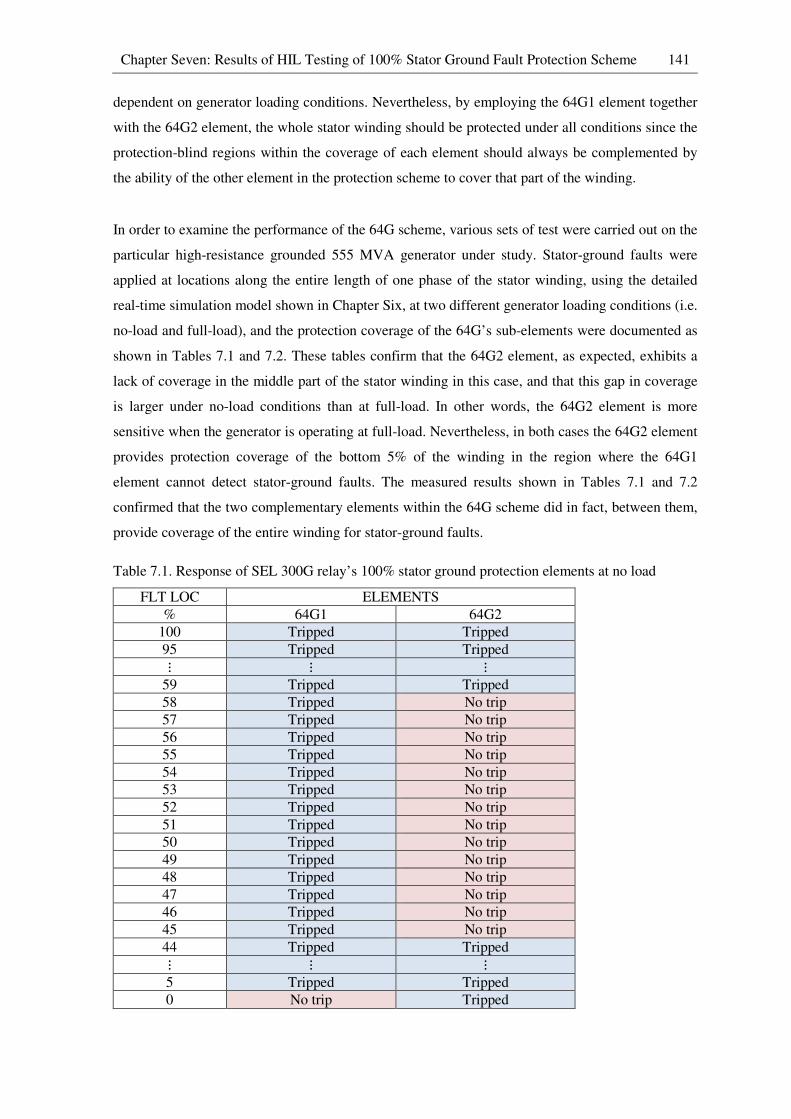
Chapter Seven: Results of HIL Testing of 100% Stator Ground Fault Protection Scheme 141
dependent on generator loading conditions. Nevertheless, by employing the 64G1 element together
with the 64G2 element, the whole stator winding should be protected under all conditions since the
protection-blind regions within the coverage of each element should always be complemented by
the ability of the other element in the protection scheme to cover that part of the winding.
In order to examine the performance of the 64G scheme, various sets of test were carried out on the
particular high-resistance grounded 555 MVA generator under study. Stator-ground faults were
applied at locations along the entire length of one phase of the stator winding, using the detailed
real-time simulation model shown in Chapter Six, at two different generator loading conditions (i.e.
no-load and full-load), and the protection coverage of the 64G’s sub-elements were documented as
shown in Tables 7.1 and 7.2. These tables confirm that the 64G2 element, as expected, exhibits a
lack of coverage in the middle part of the stator winding in this case, and that this gap in coverage
is larger under no-load conditions than at full-load. In other words, the 64G2 element is more
sensitive when the generator is operating at full-load. Nevertheless, in both cases the 64G2 element
provides protection coverage of the bottom 5% of the winding in the region where the 64G1
element cannot detect stator-ground faults. The measured results shown in Tables 7.1 and 7.2
confirmed that the two complementary elements within the 64G scheme did in fact, between them,
provide coverage of the entire winding for stator-ground faults.
Table 7.1. Response of SEL 300G relay’s 100% stator ground protection elements at no load
FLT LOC ELEMENTS
% 64G1 64G2
100 Tripped Tripped
95 Tripped Tripped ⋮ ⋮ ⋮ 59 Tripped Tripped
58 Tripped No trip
57 Tripped No trip
56 Tripped No trip
55 Tripped No trip
54 Tripped No trip
53 Tripped No trip
52 Tripped No trip
51 Tripped No trip
50 Tripped No trip
49 Tripped No trip
48 Tripped No trip
47 Tripped No trip
46 Tripped No trip
45 Tripped No trip
44 Tripped Tripped ⋮ ⋮ ⋮ 5 Tripped Tripped
0 No trip Tripped
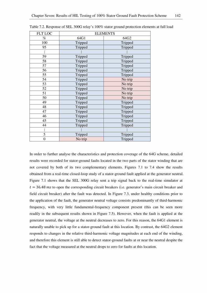
Chapter Seven: Results of HIL Testing of 100% Stator Ground Fault Protection Scheme 142
Table 7.2. Response of SEL 300G relay’s 100% stator ground protection elements at full load
FLT LOC ELEMENTS
% 64G1 64G2
100 Tripped Tripped
95 Tripped Tripped ⋮ ⋮ ⋮ 59 Tripped Tripped
58 Tripped Tripped
57 Tripped Tripped
56 Tripped Tripped
55 Tripped Tripped
54 Tripped No trip
53 Tripped No trip
52 Tripped No trip
51 Tripped No trip
50 Tripped No trip
49 Tripped Tripped
48 Tripped Tripped
47 Tripped Tripped
46 Tripped Tripped
45 Tripped Tripped
44 Tripped Tripped ⋮ ⋮ ⋮ 5 Tripped Tripped
0 No trip Tripped
In order to further analyse the characteristics and protection coverage of the 64G scheme, detailed
results were recorded for stator-ground faults located in the two parts of the stator winding that are
not covered by both of its two complementary elements. Figures 7.1 to 7.4 show the results
obtained from a real-time closed-loop study of a stator-ground fault applied at the generator neutral.
Figure 7.1 shows that the SEL 300G relay sent a trip signal back to the real-time simulator at
� = 36.48bV to open the corresponding circuit breakers (i.e. generator’s main circuit breaker and
field circuit breaker) after the fault was detected. In Figure 7.3, under healthy conditions prior to
the application of the fault, the generator neutral voltage consists predominantly of third-harmonic
frequency, with very little fundamental-frequency component present (this can be seen more
readily in the subsequent results shown in Figure 7.5). However, when the fault is applied at the
generator neutral, the voltage at the neutral decreases to zero. For this reason, the 64G1 element is
naturally unable to pick up for a stator-ground fault at this location. By contrast, the 64G2 element
responds to changes in the relative third-harmonic voltage magnitudes at each end of the winding,
and therefore this element is still able to detect stator-ground faults at or near the neutral despite the
fact that the voltage measured at the neutral drops to zero for faults at this location.

Chapter Seven: Results of HIL Testing of 100% Stator Ground Fault Protection Scheme 143
Figure 7.1. Binary logic variables for the case of a fault at the generator neutral.
Figure 7.2. Generator stator voltages for the case of a fault at the generator neutral.
Figure 7.3. Generator neutral voltage for the case of a fault at the generator neutral.
-0.05 0 0.05 0.1 0.15 0.2 0.25 0.3
0
0.5
1
FLTAPPLY
-0.05 0 0.05 0.1 0.15 0.2 0.25 0.3
0
0.5
1
X: 0.03648
Y: 1
RELAY TRIP
-0.05 0 0.05 0.1 0.15 0.2 0.25 0.3
0
0.5
1
BRKLOAD
-0.05 0 0.05 0.1 0.15 0.2 0.25 0.3
0
0.5
1
BRKFIELD
time (s)
-0.05 0 0.05 0.1 0.15 0.2 0.25 0.3
-20
-15
-10
-5
0
5
10
15
20
time (s)
Voltage (
kV
)
Gen. phase A instan. voltage
Gen. phase B instan. voltage
Gen. phase C instan. voltage
-0.05 0 0.05 0.1 0.15 0.2 0.25 0.3-1
-0.8
-0.6
-0.4
-0.2
0
0.2
0.4
0.6
0.8
1
time (s)
Voltage (
kV
)

Chapter Seven: Results of HIL Testing of 100% Stator Ground Fault Protection Scheme 144
Figure 7.4. Generator stator currents for the case of a fault at the generator neutral.
Figure 7.5. Variables recorded by the hardware relay’s event recorder for the case of a fault at the
generator neutral.
Figure 7.5 shows selected variables recorded by the SEL 300G relay’s event recorder during the
same fault study shown in Figures 7.1 to 7.4 which confirm that the 64G2 element of the relay
detected this fault and was responsible for issuing the trip signal input to the real-time simulation
model recorded in Figure 7.1. The purple trace in Figure 7.5 shows the predominance of third-
harmonic frequency in the neutral voltage prior to the fault.
Figures 7.6 to 7.9 show the results obtained from a real-time closed-loop study of a stator-ground
fault applied at a location 53% along the stator winding from the neutral end.
-0.05 0 0.05 0.1 0.15 0.2 0.25 0.3-20
-15
-10
-5
0
5
10
15
20
time (s)
Curr
ent
(kA
)
Gen. phase A instan. current
Gen. phase B instan. current
Gen. phase C instan. current
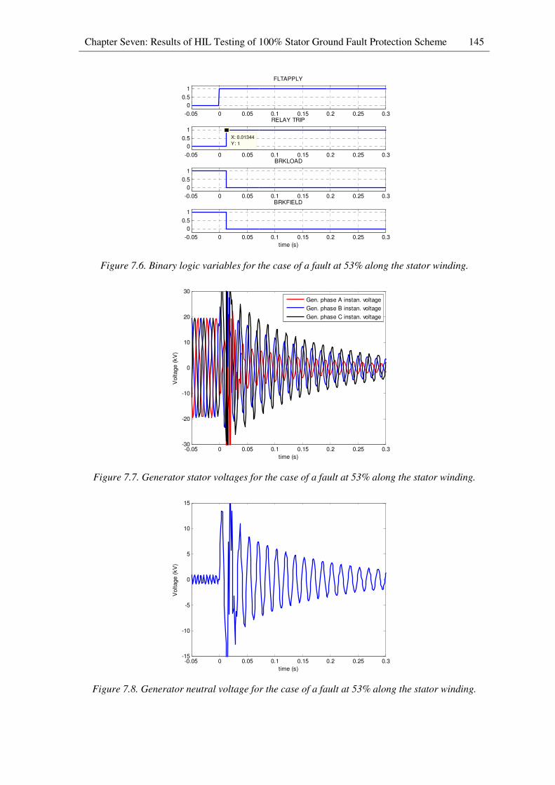
Chapter Seven: Results of HIL Testing of 100% Stator Ground Fault Protection Scheme 145
Figure 7.6. Binary logic variables for the case of a fault at 53% along the stator winding.
Figure 7.7. Generator stator voltages for the case of a fault at 53% along the stator winding.
Figure 7.8. Generator neutral voltage for the case of a fault at 53% along the stator winding.
-0.05 0 0.05 0.1 0.15 0.2 0.25 0.3
0
0.5
1
FLTAPPLY
-0.05 0 0.05 0.1 0.15 0.2 0.25 0.3
0
0.5
1
X: 0.01344
Y: 1
RELAY TRIP
-0.05 0 0.05 0.1 0.15 0.2 0.25 0.3
0
0.5
1
BRKLOAD
-0.05 0 0.05 0.1 0.15 0.2 0.25 0.3
0
0.5
1
BRKFIELD
time (s)
-0.05 0 0.05 0.1 0.15 0.2 0.25 0.3-30
-20
-10
0
10
20
30
time (s)
Voltage (
kV
)
Gen. phase A instan. voltage
Gen. phase B instan. voltage
Gen. phase C instan. voltage
-0.05 0 0.05 0.1 0.15 0.2 0.25 0.3-15
-10
-5
0
5
10
15
time (s)
Vo
ltage (
kV
)
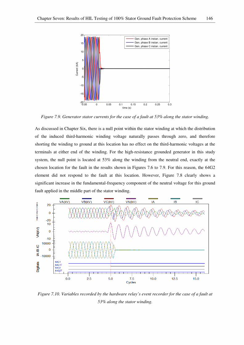
Chapter Seven: Results of HIL Testing of 100% Stator Ground Fault Protection Scheme 146
Figure 7.9. Generator stator currents for the case of a fault at 53% along the stator winding.
As discussed in Chapter Six, there is a null point within the stator winding at which the distribution
of the induced third-harmonic winding voltage naturally passes through zero, and therefore
shorting the winding to ground at this location has no effect on the third-harmonic voltages at the
terminals at either end of the winding. For the high-resistance grounded generator in this study
system, the null point is located at 53% along the winding from the neutral end, exactly at the
chosen location for the fault in the results shown in Figures 7.6 to 7.9. For this reason, the 64G2
element did not respond to the fault at this location. However, Figure 7.8 clearly shows a
significant increase in the fundamental-frequency component of the neutral voltage for this ground
fault applied in the middle part of the stator winding.
Figure 7.10. Variables recorded by the hardware relay’s event recorder for the case of a fault at
53% along the stator winding.
-0.05 0 0.05 0.1 0.15 0.2 0.25 0.3-20
-15
-10
-5
0
5
10
15
20
time (s)
Curr
ent
(kA
)
Gen. phase A instan. current
Gen. phase B instan. current
Gen. phase C instan. current
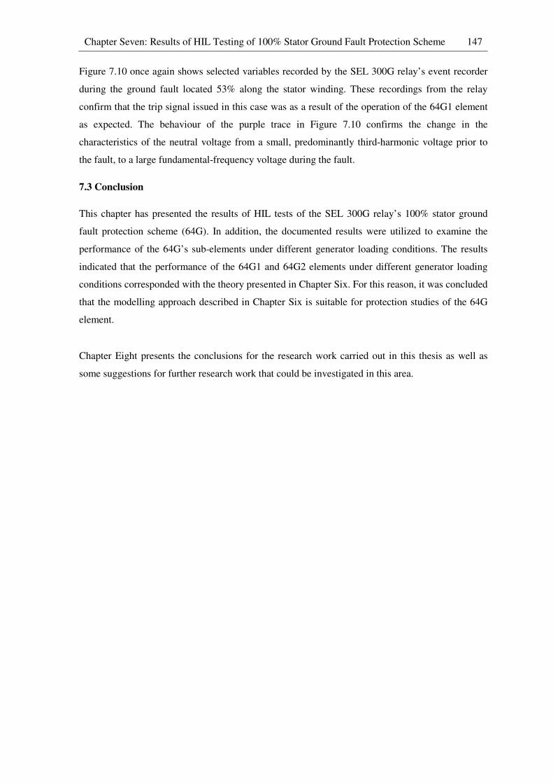
Chapter Seven: Results of HIL Testing of 100% Stator Ground Fault Protection Scheme 147
Figure 7.10 once again shows selected variables recorded by the SEL 300G relay’s event recorder
during the ground fault located 53% along the stator winding. These recordings from the relay
confirm that the trip signal issued in this case was as a result of the operation of the 64G1 element
as expected. The behaviour of the purple trace in Figure 7.10 confirms the change in the
characteristics of the neutral voltage from a small, predominantly third-harmonic voltage prior to
the fault, to a large fundamental-frequency voltage during the fault.
7.3 Conclusion
This chapter has presented the results of HIL tests of the SEL 300G relay’s 100% stator ground
fault protection scheme (64G). In addition, the documented results were utilized to examine the
performance of the 64G’s sub-elements under different generator loading conditions. The results
indicated that the performance of the 64G1 and 64G2 elements under different generator loading
conditions corresponded with the theory presented in Chapter Six. For this reason, it was concluded
that the modelling approach described in Chapter Six is suitable for protection studies of the 64G
element.
Chapter Eight presents the conclusions for the research work carried out in this thesis as well as
some suggestions for further research work that could be investigated in this area.
CHAPTER 8
CONCLUSION
8.1 Introduction
This thesis has evaluated the performance of a number of generator protection elements, namely
phase percentage restrained differential protection (87P), loss-of-field protection (40), out-of-step
protection (78) and 100% stator ground fault protection (64G), under various system contingencies
and fault scenarios, using an actual hardware generator protection relay (SEL 300G) connected in a
closed-loop configuration with a real-time simulation model of the study system. The results have
shown that the performance of each generator protection function, and the most appropriate way to
set these functions, can be better understood through real-time closed-loop studies as a result of the
ability to test these functions in a realistic manner using the new phase-domain synchronous
machine model. The validity of using the phase-domain synchronous machine model for hardware-
in-loop testing of a generator protection relay has been confirmed in this thesis and therefore
similar testing approaches can be followed for performance studies of industrial generator
protection relays in the future. This chapter summarises the conclusions of each chapter in the
thesis, and presents some suggestions for further research studies in this area in future.
8.2 Conclusions
Chapter One briefly discussed the advantages of utilizing the real-time, closed-loop testing
approach to evaluate the performance of various power system controllers and protection relays.
The chapter further explained certain limitations associated with hardware-in-loop testing of
generator protection relays when using the conventional dynamic model of a synchronous
generator to examine the performance of particular generator protection functions. Finally, the
chapter discussed the advanced features of a recently-developed, phase-domain synchronous
machine model and the motivation to carry out a thorough, research-based analysis of this new
machine model and its applicability for testing generator protection and controls using an actual
manufacturer’s protection relay hardware (SEL 300G).
Chapter Two provided some background to the research topic by presenting a general review of
power system protection together with a discussion of different protection philosophies and
relaying technologies. The chapter further reviewed the particular protection functions commonly
seen in industrial generator protection relays. In addition, the chapter discussed different
approaches to modelling synchronous generators in the real-time simulation package RSCAD as
well as different protection relay testing methodologies together with their advantages and
disadvantages. This chapter concluded that a better understanding of the performance of specific

Chapter Eight: Conclusion 149
generator protection elements, and the most appropriate way to set them, can be obtained by means
of the hardware-in-loop testing approach together with the new phase-domain synchronous
machine model. Finally, the chapter discussed the particular generator protection functions to be
focused on in the studies in this thesis, namely phase percentage restrained differential protection
(87P), loss-of-field protection (40), out-of-step protection (78) and 100% stator ground fault
protection (64G), as well as the motivation behind the focus on these particular elements.
Chapter Three presented an overview of a well-known study system that was adapted for the
purposes of testing the particular generator protection functions of interest in this thesis. The
chapter further discussed the reasons for certain modifications required in the representation of the
generators in the system as well as the development of the real-time simulation models themselves,
based on these modified study systems. In addition, the chapter provided an overview of the
particular generator protection relay (SEL 300G) used in this research project as well as the details
of the hardware-in-loop test set up and the closed-loop connections between the real-time simulator
and the SEL 300G relay. Finally, the chapter explained that by utilizing RSCAD’s generic, real-
time model of a generator protection relay in parallel with the SEL 300G relay hardware during
particular protection studies such as loss-of-field protection (40) and generator out-of-step
protection (78), it is possible to gain further insight into the operation of these protection functions
during various fault scenarios and system contingencies, which in turn, allows validation of the
practical settings chosen for these protection elements.
Chapter Four presented the theory of operation of the particular generator protective functions
(phase percentage restrained differential protection (87P), loss-of-field protection (40) and
generator out-of-step protection (78)) to be considered during the hardware-in-loop tests for the
case when low-resistance grounded generators were considered in the study system. The chapter
further presented detailed practical settings calculations for the aforementioned protection functions
based on the parameters of the particular generator and system under study. Various other settings
considerations for these protection functions were also taken into account in order to prevent
misoperation under healthy (un-faulted) generator operating conditions. The detailed settings
determined for these protection elements were then used to configure the SEL 300G relay under
test, prior to evaluating the performance of the particular protection functions using the real-time,
closed-loop testing approach.
Chapter Five presented the results of the hardware-in-loop tests of the protection elements of the
SEL 300G relay discussed in Chapter Four under different fault scenarios and system contingencies,
and the test results were analysed and discussed. In particular, the performance of the phase
percentage restrained differential protection scheme (87P) was evaluated when employed to protect

Chapter Eight: Conclusion 150
a particular low-resistance grounded generator represented in the real-time simulation model. The
results confirmed that the 87P element is not able to detect stator-ground faults that occur at or near
the generator neutral. It was concluded that the protection coverage of the 87P element depends on
the grounding resistance of the particular generator being protected and the settings of the dual-
slope differential characteristic of the 87P element. Additionally, since the new phase-domain
model available in RSCAD allows detailed and realistic representation of the circuit supplying the
field excitation to a synchronous generator, this chapter also considered the impact on the faulted
generator of different field circuit breaker failure scenarios during attempts to clear a stator-ground
fault. Using this advanced feature provided by the new phase-domain machine model, the
performances of the loss-of-field element (40) under different types of field contingency were also
evaluated. It was concluded that the trajectory of the measured positive sequence impedance during
loss-of-field conditions depends on the relative rates of change of the generator internal voltage and
rotor angle, which in turn, depend on the field circuit time constant and the initial generator loading
condition.
Finally, Chapter Five investigated the performance of a single-blinder out-of-step protection
scheme (78) using the highly-detailed, modified study system discussed in Chapter Three, in order
to study its response to both stable power swings and out-of-step conditions caused by different
system contingencies. The results have shown that the tripping characteristics of a properly-
designed 78 element can discriminate between stable and unstable generator electromechanical
swings following a system disturbance. The results also demonstrated that the trajectory of the
positive sequence impedance measured by the relay may enter the tripping characteristics of its 40
(loss-of-field) element during a stable recovery swing following a severe system disturbance.
However, since there was appropriate delay time introduced into the tripping characteristics of the
40 element, misoperation of the 40 element was prevented during the worst-case system
disturbance.
Chapter Six reviewed the theory of high-resistance grounding schemes for generators and presented
the design of a representative high-resistance grounding scheme for the studied generators
following standard design procedures recommended in the technical literature. Additionally, the
chapter discussed the theory of operation of various protection schemes that are typically employed
to protect high-resistance grounded generators. It was concluded that the 100% stator ground fault
protection scheme available on the SEL 300G relay (64G), which comprises a fundamental-
frequency neutral overvoltage element (64G1) and a third-harmonic voltage differential element
(64G2), is able to provide full stator winding protection for high-resistance grounded generators
under all generator loading conditions. As discussed in Chapter Two, the publicly-available version
of the phase-domain synchronous machine model used in the work of this thesis does not represent
Chapter Eight: Conclusion 151
phase-belt harmonics in the generator stator winding, and therefore it is not able to represent the
third-harmonic voltages in these windings that are relied upon by the 64G2 element to detect stator-
ground faults. Chapter Six therefore also presented an additional custom-designed, extension to the
real-time simulation model of the generator that was developed in this thesis in order to be able to
simulate the characteristics of the third-harmonic winding voltages that are relied upon by the 64G2
element to detect stator-ground faults. Finally, Chapter Six presented practical settings calculations
for the 64G scheme based on the parameters of the particular high-resistance grounded generator
under study, and the settings were used to configure the SEL 300G relay under test prior to
evaluating the performance of the 64G scheme using the real-time, closed-loop testing approach.
Chapter Seven presented the results of the hardware-in-loop tests of the SEL 300G relay’s 100%
stator ground fault (64G) protection scheme. The results have shown that the 64G scheme can
provide full stator winding protection for the particular high-resistance grounded generator studied,
under both no-load and full-load generator operating conditions. The results were also able to
demonstrate the performances of the individual elements making up the 64G scheme, namely the
64G1 and 64G2 elements. The protection coverage of both the 64G1 and 64G2 elements was
confirmed during this particular protection study and the results were seen to correspond with the
theory presented in Chapter Six regarding the protection-blind regions of these two protection
elements.
The real-time simulation results have shown that by using the RSCAD’s phase-domain
synchronous machine model, together with some supplementary modelling to represent the third-
harmonic voltages within the generator stator windings, it is possible to evaluate the performances
of various generator protective functions which could not otherwise be achieved using conventional
dynamic synchronous machine models. Furthermore, it is now possible to validate the settings of
various generator protection elements under different realistic fault scenarios and system
contingencies using similar hardware-in-loop, closed-loop testing procedures to those already
widely adopted for other forms of power system protection.
Finally, some recommendations for further research that could be pursued as an extension of the
work in this thesis are contained in the following section.
8.3 Suggestion for further work
The work presented in this thesis has confirmed the validity of using a real-time, phase-domain,
synchronous machine model to directly test the performances of various generator protective
functions using hardware-in-loop techniques.

Chapter Eight: Conclusion 152
UNIT4
UNIT3
UNIT2
UNIT1
Transmission lines
Infinite
bus
I’s V’s
BRK
StatusTrip
REAL-TIME MODEL
EXTERNAL HARDWARE
Filter
Rn
Analogue
Output
Digital
Output
Digital
Input
Analogue
Amplifier
Digital
Amplifier
Generator
Protection Relay
Neutral Injection
Equipment
Figure 8.1. Schematic diagram showing proposed real-time, closed-loop testing of a neutral
injection scheme (64S).
Figure 8.2. Schematic diagram showing real-time closed-loop testing of an automatic voltage
regulator.
Chapter Eight: Conclusion 153
Following a similar hardware-in-loop testing approach, it should be possible to examine the
performances of other stator winding protection schemes that were not considered in this thesis (e.g.
ground differential protection (87N) or neutral injection (64S) schemes). Figure 8.1 shows a
schematic diagram of how the performance of a 64S scheme could be evaluated using the real-time
simulator, closed-loop testing approach. Using the kind of detailed and realistic real-time models of
the generator plant described in Chapter Six, together with real-time models of the additional
neutral injection equipment that forms part of such schemes, it should be possible to study the
performance of a generator protection relay equipped with a 64S scheme under different fault
scenarios.
Furthermore, because of the improved representation of the field winding in the real-time, phase-
domain synchronous machine model, it is now possible to include detailed representations of the
excitation system plant (including its power electronics) of a synchronous generator within a real-
time simulation model. As a result, the effects of different types of practical fault scenarios within
the power electronic devices of the excitation systems feeding the generator can now be studied. In
addition, the performance of the actual controllers used for generator excitation system control can
also be evaluated using hardware-in-loop techniques. Figure 8.2 is a schematic diagram showing
how an automatic voltage regulator can be connected to a real-time model in a closed-loop
configuration in order to conduct different studies for performance evaluation. With such a test set
up, one could also study the effects of bus-fed and non-bus-fed excitation systems and their
controls during a system disturbance, and the effects of such controls on generator protection
systems.
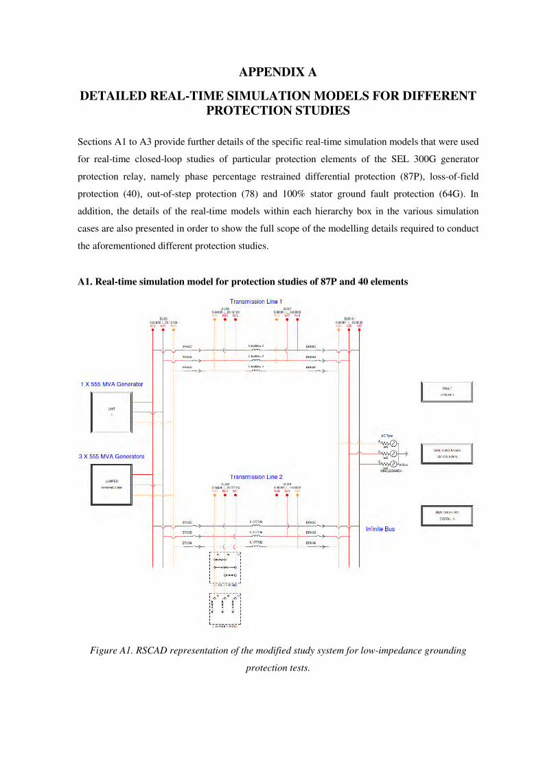
APPENDIX A
DETAILED REAL-TIME SIMULATION MODELS FOR DIFFERENT
PROTECTION STUDIES
Sections A1 to A3 provide further details of the specific real-time simulation models that were used
for real-time closed-loop studies of particular protection elements of the SEL 300G generator
protection relay, namely phase percentage restrained differential protection (87P), loss-of-field
protection (40), out-of-step protection (78) and 100% stator ground fault protection (64G). In
addition, the details of the real-time models within each hierarchy box in the various simulation
cases are also presented in order to show the full scope of the modelling details required to conduct
the aforementioned different protection studies.
A1. Real-time simulation model for protection studies of 87P and 40 elements
Figure A1. RSCAD representation of the modified study system for low-impedance grounding
protection tests.
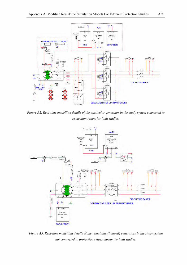
Appendix A: Modified Real-Time Simulation Models For Different Protection Studies A.2
Figure A2. Real-time modelling details of the particular generator in the study system connected to
protection relays for fault studies.
Figure A3. Real-time modelling details of the remaining (lumped) generators in the study system
not connected to protection relays during the fault studies.
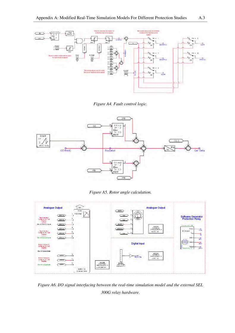
Appendix A: Modified Real-Time Simulation Models For Different Protection Studies A.3
Figure A4. Fault control logic.
Figure A5. Rotor angle calculation.
Figure A6. I/O signal interfacing between the real-time simulation model and the external SEL
300G relay hardware.
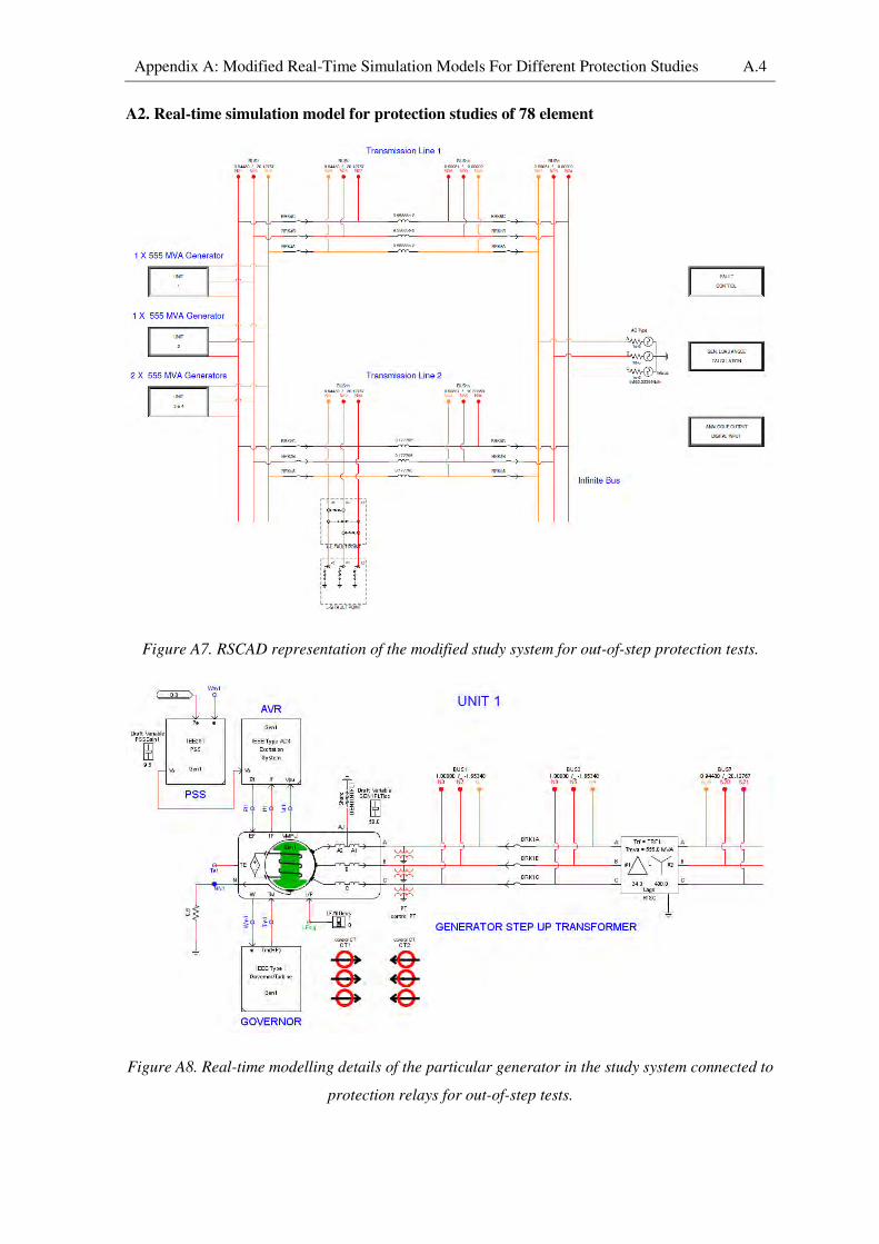
Appendix A: Modified Real-Time Simulation Models For Different Protection Studies A.4
A2. Real-time simulation model for protection studies of 78 element
Figure A7. RSCAD representation of the modified study system for out-of-step protection tests.
Figure A8. Real-time modelling details of the particular generator in the study system connected to
protection relays for out-of-step tests.
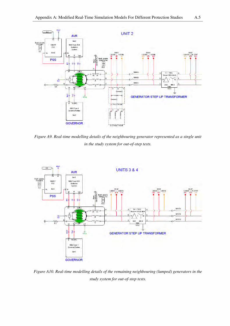
Appendix A: Modified Real-Time Simulation Models For Different Protection Studies A.5
Figure A9. Real-time modelling details of the neighbouring generator represented as a single unit
in the study system for out-of-step tests.
Figure A10. Real-time modelling details of the remaining neighbouring (lumped) generators in the
study system for out-of-step tests.
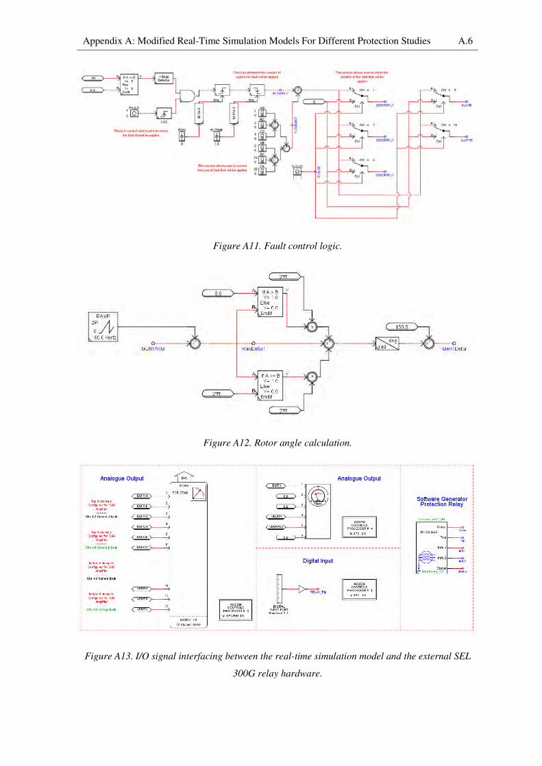
Appendix A: Modified Real-Time Simulation Models For Different Protection Studies A.6
Figure A11. Fault control logic.
Figure A12. Rotor angle calculation.
Figure A13. I/O signal interfacing between the real-time simulation model and the external SEL
300G relay hardware.
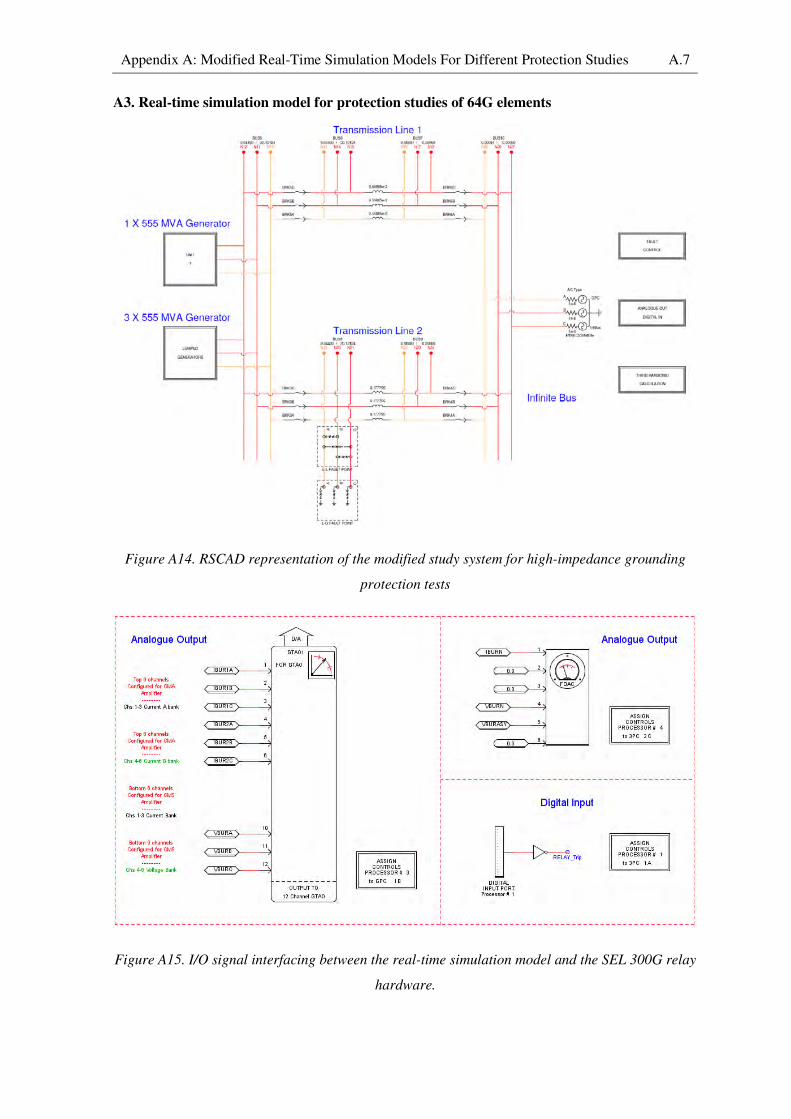
Appendix A: Modified Real-Time Simulation Models For Different Protection Studies A.7
A3. Real-time simulation model for protection studies of 64G elements
Figure A14. RSCAD representation of the modified study system for high-impedance grounding
protection tests
Figure A15. I/O signal interfacing between the real-time simulation model and the SEL 300G relay
hardware.

Appendix A: Modified Real-Time Simulation Models For Different Protection Studies A.8
Figure A16. Real-time modelling details of the particular generator in the study system connected
to protection relays for fault studies.
Figure A17. Real-time modelling details of the remaining (lumped) generators in the study system
not connected to protection relays during the fault studies.
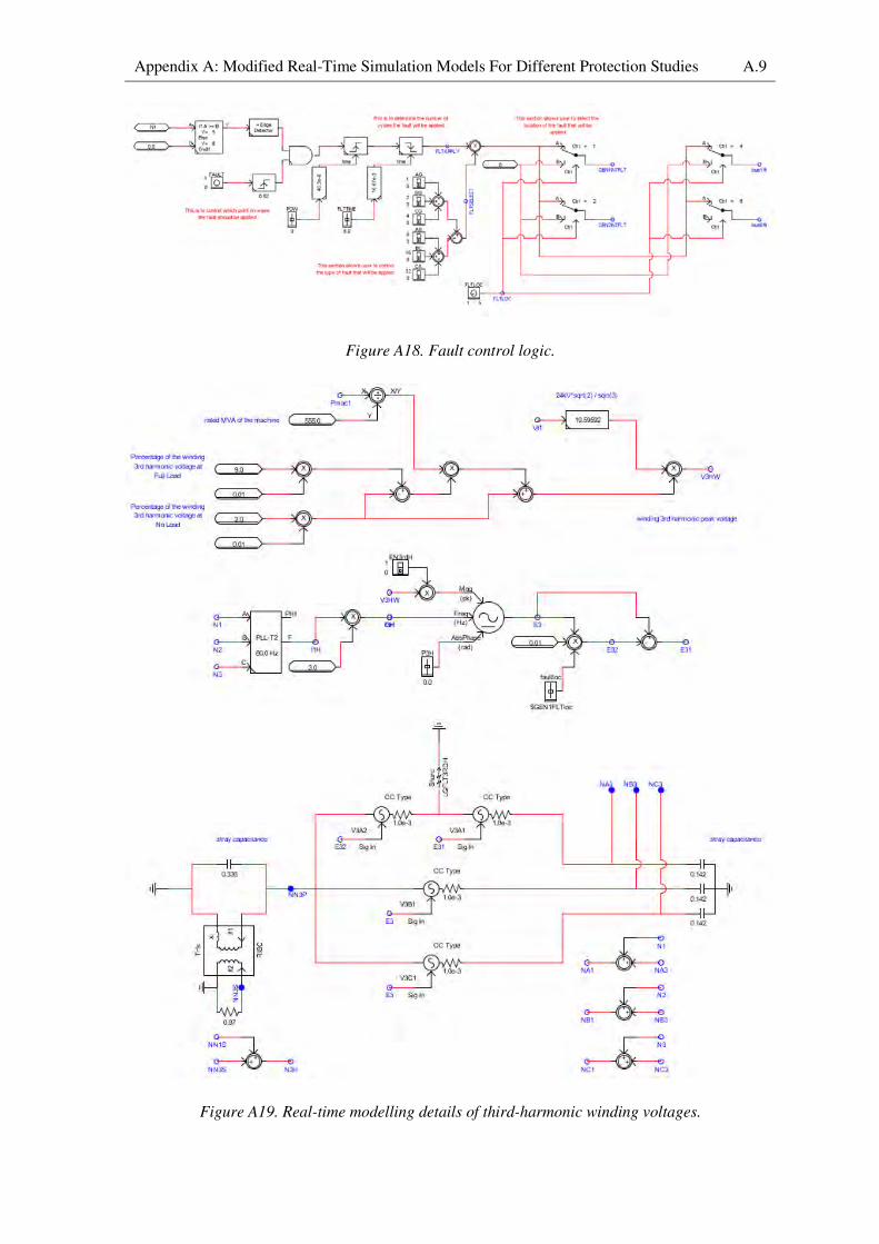
Appendix A: Modified Real-Time Simulation Models For Different Protection Studies A.9
Figure A18. Fault control logic.
Figure A19. Real-time modelling details of third-harmonic winding voltages.
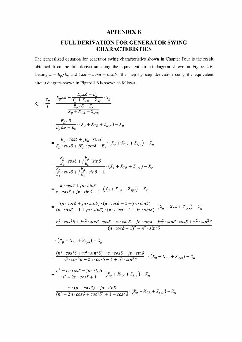
APPENDIX B
FULL DERIVATION FOR GENERATOR SWING
CHARACTERISTICS
The generalized equation for generator swing characteristics shown in Chapter Four is the result
obtained from the full derivation using the equivalent circuit diagram shown in Figure 4.6.
Letting : = "g/"; and 1∠h = cLVh + iVK:h , the step by step derivation using the equivalent
circuit diagram shown in Figure 4.6 is shown as follows.
Y# = *#7 = "g∠h − "g∠h − ";g̀ + `B# + Y;\; ∙ g̀"g∠h − ";g̀ + `B# + Y;\;
= "g∠h"g∠h − "; ∙ j g̀ + `B# + Y;\;k − g̀
= "g ∙ cLVh + i"g ∙ VK:h"g ∙ cLVh + i"g ∙ VK:h − "; ∙ j g̀ + `B# + Y;\;k − g̀
= "g"; ∙ cLVh + i "g"; ∙ VK:h"g"; ∙ cLVh + i "g"; ∙ VK:h − 1 ∙ j g̀ + `B# + Y;\;k − g̀
= : ∙ cLVh + i: ∙ VK:h: ∙ cLVh + i: ∙ VK:h − 1 ∙ j g̀ + `B# + Y;\;k − g̀
= (: ∙ cLVh + i: ∙ VK:h) ∙ (: ∙ cLVh − 1 − i: ∙ VK:h)(: ∙ cLVh − 1 + i: ∙ VK:h) ∙ (: ∙ cLVh − 1 − i: ∙ VK:h) ∙ j g̀ + `B# + Y;\;k − g̀
= :� ∙ cLV�h + i:� ∙ VK:h ∙ cLVh − : ∙ cLVh − i: ∙ VK:h − i:� ∙ VK:h ∙ cLVh + :� ∙ VK:�h(: ∙ cLVh − 1)� + :� ∙ VK:�h
∙ j g̀ + `B# + Y;\;k − g̀
= (:� ∙ cLV�h + :� ∙ VK:�h) − : ∙ cLVh − i: ∙ VK:h:� ∙ cLV�h − 2: ∙ cLVh + 1 + :� ∙ VK:�h ∙ j g̀ + `B# + Y;\;k − g̀
= :� − : ∙ cLVh − i: ∙ VK:h:� − 2: ∙ cLVh + 1 ∙ j g̀ + `B# + Y;\;k − g̀
= : ∙ (: − cLVh) − i: ∙ VK:h(:� − 2: ∙ cLVh + cLV�h) + 1 − cLV�h ∙ j g̀ + `B# + Y;\;k − g̀
Appendix B: Full Derivation For Generator Swing Characteristics B.2
= : ∙ (: − cLVh) − iVK:h(: − cLVh)� + VK:�h ∙ j g̀ + `B# + Y;\;k − g̀
When the special case in which"g = ";(: = 1) is evaluated, the equation becomes
Y# = *#7 = (1 − cLVh) − iVK:h(1 − cLVh)� + VK:�h ∙ j g̀ + `B# + Y;\;k − g̀
= (1 − cLVh) − iVK:h1� − 2 ∙ cLVh + cLV�h + VK:�h ∙ j g̀ + `B# + Y;\;k − g̀
= (1 − cLVh) − iVK:h2 − 2 ∙ cLVh ∙ j g̀ + `B# + Y;\;k − g̀
= l1 − cLVh − iVK:h1 − cLVh m ∙ j g̀ + `B# + Y;\;k2 − g̀
= l1 − iVK:h1 − cLVhm ∙ j g̀ + `B# + Y;\;k2 − g̀
= u1 − i √VK:�h1 − cLVhv ∙ j g̀ + `B# + Y;\;k2 − g̀
= u1 − i √1 − cLV�h1 − cLVh v ∙ j g̀ + `B# + Y;\;k2 − g̀
= u1 − i�(1 − cLVh) ∙ (1 + cLVh)1 − cLVh v ∙ j g̀ + `B# + Y;\;k2 − g̀
= u1 − i √1 + cLVh√1 − cLVhv ∙ j g̀ + `B# + Y;\;k2 − g̀
= �1 − i √1 + cLVh2√1 − cLVh2 � ∙ j g̀ + `B# + Y;\;k2 − g̀
= �1 − i cLV �h2�VK: �h2�� ∙j g̀ + `B# + Y;\;k2 − g̀
= t1 − icL� lh2mz ∙ j g̀ + `B# + Y;\;k2 − g̀

REFERENCES
[1] Power System Relaying Committee: “Performance of Generator Protection During Major
System Disturbances”, IEEE Transactions in Power Delivery, 2003.
[2] Power System Relay Committee: “Coordination of Generator Protection with Generator
Excitation Control and Generator Capability”, IEEE Power Engineering Society General
Meeting, 2007.
[3] Power System Relaying Committee: “Voltage Collapse Mitigation”, Report to IEEE power
System Relaying Committee, December 1996.
[4] P.G. McLaren, R. Kuffel, R. Wierckx, J. Giesbrecht, L. Arendt: “A Real Time Digital
Simulator for Testing Relays”, IEEE Transactions on Power Delivery, Vol. 7, No.1,
January 1992.
[5] R. Kuffel, J. Giesbrecht, T. Maguire, R.P. Wiercks, P. McLaren: “RTDS – A Fully Digital
Power System Simulator Operating in Real Time”, WESCANEX 95, Communications,
Power, and Computing Conference Proceedings, IEEE Vol. 2, May 1995, pp. 300 – 305.
[6] Paul Forsyth, Trevor Maguire, Rick Kuffel: “Real Time Digital Simulation for Control and
Protection System Testing”, IEEE Power Electronics Specialists Conference, Vol. 1, June
2004, pp. 329 – 335.
[7] R. Kuffel, P. McLaren, M. Yalla, X. Wang: “Testing of the Beckwith Electric M-0430
Multifunction Protection Relay Using a Real-Time Simulator (RTDS)”, Conference
Proceedings of ICDS, College Station, Texas, USA, April 1995, pp. 49 – 54.
[8] R.J. Marttila: “Testing of Integrated Multifunction Protection Systems on the Real-Time
Digital Simulator, Conference Proceedings of ICDS, Montreal, Canada, May 1997, pp. 177
– 182.
[9] T. Badelt, M. Claus, B. Friedrich, D. Retzmann, S. Boshoff, P. Davel, P. Forsyth, T.L.
Maguire: “Advanced SVC Testing using a Real Time Digital Simulator, Conference
Proceedings of ICDS, Montreal, Canada, May 1997, pp. 265 – 270.
[10] A.B. Dehkordi, Prabhakar Neti, A.M. Gole, T.L. Maguire: “Development and Validation
of a Comprehensive Synchronous Machine Model for a Real-Time Environment”, IEEE
Trans. Energy Conversion, Vol. 25, No. 1, 2010, pp. 34 – 48.
[11] Prabha Kundur: Power System Stability and Control, McGraw-Hill Inc., New York, 1994.

References R.2
[12] P.G. McLaren, E.N. Dirks, R.P. Jayasinghe, G.W. Swift, Z. Zhang: “Using a Real Time
Digital Simulator to Develop an Accurate Model of a Digital Relay”, Conference
Proceedings of ICDS, College Station, Texas, USA, April 1995, pp. 173 – 178.
[13] “Real-Time Digital Simulator Power System Users Manual”, RTDS Technologies,
Winnipeg, Manitoba, Canada, November 2006.
[14] H. Duchen, M. Lagerkvist, R. Kuffel, R. Wierckx: “HVDC Simulation and Control Testing
using a Real Time Digital Simulator (RTDS), Conference Proceedings of ICDS, College
Station, Texas, USA, April 1995, pp. 213 – 218.
[15] R. Kuffel, R. Wierckx, P. Forsyth, H. Duchen, M. Lagerkvist, P. Holmberg, X. Wang:
“Expanding an Analogue Simulator’s Modelling Capability Using a Real-Time Digital
Simulator”, Conference Proceedings of ICDS, College Station, Texas, USA, April 1995,
pp. 199 – 204.
[16] K. Bergmann, K. Braun, G. Kuhn, D. Retzmann, I. Baran, F. Pereira, P. Forsyth, T.L.
Maguire: “Advanced Fully Digital TCSC Real-Time Simulation in Comparison with
Computer Studies and On-site Testing, Conference Proceedings of ICDS, Vasteras,
Sweden, May 1999.
[17] Dean S. Ouellette, Rudi P. Wierckx, Peter G. McLaren: “Using a Multi-threaded Time Step
to Model a Multi-function Relay in a Real Time Digital Simulator”, Developments in
Power System Protection (DPSP 08), Glasgow, March 2008.
[18] A.B. Dehkordi, D.S. Ouellette, P.A. Forsyth: “Protection Testing of A 100% Stator Ground
Fault Using A Phase Domain Synchronous Machine Model in Real Time”, IET
International Conference on Developments in Power System Protection, January 2010.
[19] Y-T Huang, B S Rigby, A B Dehkordi: “Using a new faulted synchronous machine model
for hardware-in-loop testing of a generator protection relay”, Southern African Power
System Protection Conference, 2012.
[20] Y-T Huang, B S Rigby: “Design and Real-Time Simulator Testing of Generator Protection
Schemes for Low- and High-Impedance Grounding Methods”, PAC World Conference,
Cape Town, 2013.
[21] J. Lewis Blackburn, Thomas J. Domin: Protective Relaying Principles and Applications,
Third Edition, Taylor and Francis Group, LLC, 2007.

References R.3
[22] Antonio Gomez-Exposito, Antonio J. Conejo, Claudio Canizares: Electric Energy Systems
Analysis and Operation, Taylor and Francis Group, LLC, 2009.
[23] P.M. Anderson: Power System Protection, John Wiley & Sons, Inc., New York, 1999.
[24] Stanley H. Horowitz, Arun G. Phadke: Power System Relaying, Third Edition, John Wiley
& Sons, Ltd., England, 2008.
[25] A.R. van C. Warrington, “Protective Relays”, Vol.1, Chapman & Hall, 1968.
[26] Moketjema Clarence Leoaneka: “Dynamic Performance of Numerical Distance Protection
Relays in Heavily Series Compensated Networks”, University of KwaZulu-Natal, 2009.
[27] R.E. Cosse: “Turbine/Generator Governor Droop/Isochronous Fundamentals – A Graphical
Approach”, Petroleum and Chemical Industry Conference, September 2011.
[28] Alexander Murdoch, Robert W. Delmerico, Sundar Venkataraman, Rodney A. Lawson,
James E. Curran, William R. Pearson: “Excitation System Protective Limiters and Their
Effect on Volt/Var Control – Design, Computer Modelling, and Field Testing”, IEEE
Transactions on Energy Conversion, Vol. 15, No. 4, December 2000.
[29] Surge Protective Devices Committee, “IEEE Guide for the Application of Neutral
Grounding in Electrical Utility Systems, Part II – Grounding of Synchronous Generator
Systems”, IEEE C62.92-1989.
[30] Substation Committee: “IEEE Standard Electrical Power System Device Function
Numbers”, IEEE Std C37.2-1991.
[31] “SEL-300G Multifunction Generator Relay Instruction Manual”, Schweitzer Engineering
Laboratories, Inc., 2007.
[32] Donald Reimert: Protective Relaying for Power Generation Systems, Taylor & Francis
Group, New York, 2006.
[33] L.G. Hewitson, Mark Brown and Ramesh Balakrishnan: Power System Protection, pp.207-
225, Elsevier Ltd, 2005.
[34] Power System Relaying Committee: “IEEE Guide for AC Generator Protection”, IEEE Std
C37.102-1995.
[35] G.J. Lloyd, H.T. Yip, G. Millar: “Operation, Design and Testing of generator 100% Stator
Earth Fault Protection Using Low Frequency Injection”, IET 9th International conference on
Developments in Power System Protection, 2008.

References R.4
[36] Rotating Machinery Protection Subcommittee: “Loss-of-Field Relay Operation during
System Disturbances”, IEEE Transactions on Power Apparatus and Systems, Vol. PAS-94,
No. 5, September/October 1975.
[37] Charles R. Arndt, McClennon Rogers: “A Study of Loss-of-Excitation Relaying and
Stability of a 555 MVA Generator on the Detroit Edison System”, IEEE Transactions on
Power Apparatus and Systems, Vol. PAS-94, No. 5, September/ October 1975.
[38] Rotating Machinery Protection Subcommittee: “Out of Step Relaying for Generators”,
IEEE Transactions on Power Apparatus and Systems, Vol. PAS-96, No. 5,
September/October 1977.
[39] Electric Machinery Committee: “IEEE Standard for Cylindrical-Rotor 50 Hz and 60 Hz
Synchronous Generators Rated 10 MVA and Above”, IEEE/ANSI C50.14, 2006.
[40] Power System Relaying Committee: “IEEE Guide for Abnormal Frequency”, IEEE Std
C37.106-1987.
[41] Rationalized User Specification: “Electricity Supply – Quality of Supply, Part 2: Voltage
Characteristics, Compatibility Levels, Limits and Assessment Methods”, Technology
Standardization Department (TSD), Eskom, 1993.
[42] U.A. Bakshi, M.V. Bakshi: “Protection and Switchgear”, Technical Publications Pune,
India, 2006.
[43] “Differential Protection SPAD 346 C3 Application and Setting Guide”, ABB, 2005.
[44] J.W. Pope , “A comparison of 100% Stator Ground Fault Protection Schemes for Generator
Stator Windings”, IEEE Transactions on Power Apparatus and Systems, Vol. PAS-103, No.
4, April 1984, pp. 832 -840.
[45] C.H. Griffin, J.W. Pope, “Generator Ground Fault Protection Using Overcurrent,
Overvoltage, and Undervoltage Relays”, IEEE Transactions on Power Apparatus and
Systems, Vol. PAS-101, No. 12, December 1982, pp. 4490 – 4501.
[46] R.L. Schlake, G.W. Buckley, G. McPherson, “Performance of Third Harmonic Ground
Fault Protection Schemes for Generator Stator Windings”, IEEE Transactions on Power
Apparatus and Systems, Vol. PAS-100, No. 7, July 1981, pp. 3195 – 3202.
[47] N. Salomon, “New Experiences in the Application of 100% Stator Earth Fault Protection
Relays Evaluating the 3rd
Harmonic of the Generator Voltage”.
References R.5
[48] M. Fulczyk, R. Mydlikowski, “Influence of Generator Load Conditions on Third-Harmonic
Voltages in Generator Stator Winding”, IEEE Transactions on Energy Conversion, Vol. 20,
No. 1, March 2005, pp. 158 – 165.
[49] R.J. Marttila, “Design Principles of A New Generator Stator Ground Relay for 100%
Coverage of the Stator Winding”, IEEE Transactions on Power Delivery, Vol. PWRD-1,
No. 4, October 1986, pp. 41 – 51.
[50] L. Pazmandi, “Stator Earth-Leakage Protection for Large Generators”, IEEE Transactions
on Power Apparatus and Systems, Vol. PAS-94, No. 4, July/August 1975, pp. 1436 – 1439.