investigation of a twisted-tube type shell-and-tube heat
TRANSCRIPT
June 2009Erling Næss, EPT
Master of Science in Energy and EnvironmentSubmission date:Supervisor:
Norwegian University of Science and TechnologyDepartment of Energy and Process Engineering
Investigation of a twisted-tube typeshell-and-tube heat exchanger
Sven Olaf Danielsen


Problem DescriptionThe following should be considered in the project work:
1. Perform a literature study on the twisted tube heat exchanger concept, which should include:
The heat exchanger design, industrial experience and thermal-hydraulic characteristics.Depending on available information, operational and maintenance experiences shall be presented.
A comparison of the twisted tube heat exchanger concept to other competing heat exchangerconcepts.The information shall be presented and discussed.
2. Collect data of thermal-hydraulic performance on the twisted-tube heat exchanger installed atMelkøya (25-HA-113). Analyze and present the data, and perform an uncertainty analysis.
3. Perform thermal-hydraulic simulations on the heat exchanger by using the HTRI program Xist.Simulate various operation modes. Therafter, compare and discuss the simulations with the datagathered in point 2. Evaluate and comment deviations between the measured data and thesimulations.
4. Comparative thermal-hydraulig designs of the twisted-tube heat exchanger 25-HA-113 withother types of shell-and-tube heat exchanger configurations. The HTRI program Xist shall be usedin the design calculations. The results shall be presented and discussed. With basis in theperformed designs, a heat exchanger concept/geometry shall be recommended for the presentapplication.
5. Suggest further work on this topic.
Assignment given: 20. January 2009Supervisor: Erling Næss, EPT


vi

vii
viii
Abstract This master thesis investigates twisted tube type shell-and-tube heat exchangers with emphasis on thermal-hydraulic characteristics, fouling and vibration properties. An extensive literature study has been carried out in order to map all published research reports written on the topic. The mapping of performed research shows that the available information is limited. Mathematical correlations for twisted tube thermal-hydraulic characteristics are extracted from the research reports found in the literature study. Correlations for convective heat transfer coefficients and pressure loss for both shell side and tube side are presented. The enhancement of heat transfer by swirl flow in a twisted tube bundle is also discussed. Measurements on thermal-hydraulic characteristics are collected from a twisted tube heat exchanger installed at the process facility LNG Hammerfest situated at the northern end of Norway. These measurements are then compared to output from the heat exchanger design software HTRI Xchanger Suite. The calculation accuracy of the twisted tube program module is predicted on this basis. HTRI Xchanger Suite can evaluate heat exchanger design in two different modes. Simulation mode calculates two outlet parameters and thereby the duty, while rating mode calculates only one output parameter where the duty is specified by the user. In rating mode the software has an accuracy of +/-4% for temperature, flow and duty calculations. The overall heat transfer coefficient is miscalculated by approximately +50% and the shell side pressure loss is miscalculated by +40%. In simulation mode the duty is not specified by the user and the program may calculate two output parameters. The predicted accuracy depends on the calculated parameters. Calculation accuracy for two unknown outlet temperatures is +/-7% while calculation accuracy for two unknown mass flow rates is up to +200%. The accuracy on the overall heat transfer coefficient and shell side pressure loss is the same as for rating mode. The StatoilHydro twisted tube heat exchanger 25-HA-113 design on LNG Hammerfest is evaluated with respect to thermal-hydraulic characteristics. 25-HA-113 is operated with other flows and temperatures than it was designed for. By use of a mathematical method the expected performance in design operation point is predicted. By analysing the measured overall heat transfer coefficient and by use of this mathematical method, it is stated that the heat exchanger has insufficient thermal design. However, investigation of the pressure loss in the same manner shows that the unit performs better than specified in the design basis. The fouling characteristic is examined by evaluation of the overall heat transfer coefficient over a time period. This analysis shows that the fouling tendency is minimal. By use of the computer program HTRI Xchanger Suite and field measurements a quantitative comparison of a twisted tube, a helix baffled and a single segmental baffled unit is performed for the application of 25-HA-113. The alternatives are compared to each other by evaluation of heat transfer coefficients, pressure loss, fouling characteristics and vibration risks. The conventional and the helix alternative are equipped with low fin tubes which show a somehow higher heat transfer capacity per volume unit. However, the twisted tube provides a higher overall heat transfer coefficient than the two other alternatives. The single segmental baffle concept appears to have the lowest shell side pressure loss, followed closely by the twisted tube. With respect to vibration risk the twisted tube has a superior performance compared the two competing concepts due to a very rigid bundle construction. By considering the thermal hydraulic characteristics and the vibration risk connected to the evaluated application the twisted tube is the recommended alternative.

ix
Sammendrag Denne masteroppgaven undersøker rørsatsvarmevekslere med såkalte ”twisted tubes”. Det vil si at rørene har et ovalt tverrsnitt som er vridd om rørets lengdeakse. Denne typen varmevekslere har blitt undersøkt med hovedvekt på termisk-hydrauliske egenskaper, beleggdannelse og risiko for vibrasjonsproblemer. Et omfattende litteraturstudium har blitt gjennomført for å samle mest mulig informasjon om tidligere forskning på dette området. Denne undersøkelsen viser at publisert forskningsarbeid som omfatter slike varmevekslere er av begrenset omfang og tilgjenglighet. Matematiske korrelasjoner for termisk-hydrauliske egenskaper er ekstrahert fra relevante forskningsrapporter funnet i litteraturstudiet. Korrelasjoner for konvektiv varmeovergang og trykktap er presentert for både rør og skall side av veksleren. Økt varmeovergang ved indusering av virvelstrøm er også diskutert. Målinger av termisk-hydrauliske egenskaper er samlet fra en varmeveksler som er installert ved LNG Hammerfest på Melkøya. Disse målingene er deretter sammenlignet med beregninger fra dataprogrammet HTRI Xchanger Suite. Med bakgrunn i denne sammenligningen er beregningsnøyaktigheten til twisted tube modulen i programmet evaluert. HTRI Xchanger Suite evaluerer en eksisterende varmeveksler design i to ulike moduser. Simulation modus evner å beregne to ulike prosessparametere og således varmeeffekten til veksleren. I rating modus kan programmet kun beregne en prosessparameter. Varmeeffekten er dermed gitt implisitt av brukeren. Rating modus beregner temperaturer, masserater og varmeeffekt med en nøyaktighet på +/- 4%. Varmeovergangstall og trykktap på skall side blir beregnet for store med henholdsvis +50% og +40% nøyaktighet. I simuleringsmodus avhenger nøyaktigheten av hvilke to parametere som beregnes av programmet. Beregningsnøyaktigheten er lav når begge masseratene er ukjente, med opp mot +200% feilkalkulering. Beregninger gjort med to temperaturer ukjente er derimot høy, med +/- 7%. Nøyaktigheten for beregning av trykktap og varmeovergangstall er den samme i simulation som rating modus. 25-HA-113 twisted tube varmeveksleren installert på LNG Hammerfest er undersøkt med hensyn på termisk-hydraulisk design. Varmeveksleren opereres ved et annet driftspunkt enn det som er spesifisert i design basisen. Ved å bruke en matematisk metode kan den forventede ytelsen i design punkt likevel predikeres. Denne analysen viser at det termiske designet av veksleren ikke er tilstrekkelig. Trykk tap på skall side er undersøkt ved hjelp av den samme metoden. Denne undersøkelsen viser at trykktapet er lavere enn forventet av leverandøren og lavere enn krav spesifisert i design basisen. Beleggdannelsen er også undersøkt. Dette ble gjort ved å evaluere utviklingen av varmeovergangstallet i en gitt tidsperiode. Denne analysen viser at beleggdannelsen i veksleren er minimal. Ved å bruke dataprogrammet HTRI Xchanger Suite og måledata har en kvantitativ undersøkelse av ytelsen til tre ulike varmevekslerkonsepter blitt gjennomført for anvendelse på 25-HA-113. De tre evaluerte konseptene er twisted tube, heliks bafflet og single segmentellt bafflet varmeveksler. Disse tre løsningene er blitt evaluert med tanke på varmeovergangstall, trykktap, beleggdannelse og vibrasjon risiko. Det konvensjonelle alternativet og helix veksleren er utstyrt med finnede rør som har en noe høyere varmeoverføringskapasitet. Likevel har twisted tube høyere varmeovergangstall. Den konvensjonelle veksleren med segmentelle baffler viser seg å påføre det laveste trykktapet på skall side, tett fulgt av twisted tube. I forhold til vibrasjonsrisiko viser twisted tube seg overlegen de to andre alternativene på grunn av den stive rørsatskonstruksjonen. Etter vurdering av termisk hydrauliske egenskaper og vibrasjonsrisikoen knyttet til denne anvendelsen anbefales twisted tube i valget mellom de tre alternativene.

x
Table of contents
FIGURE INDEX XIII
TABLE INDEX XIV
NOMENCLATURE XV
ABBREVIATIONS XVIII
1 INTRODUCTION 1
2 THE TWISTED TUBE HEAT EXCHANGER CONCEPT 2
2.1 HISTORY 2 2.2 GEOMETRY 2 2.3 THERMAL-HYDRAULIC CHARACTERISTICS 5 2.3.1 ENHANCEMENT OF HEAT TRANSFER BY INDUCING SWIRL 5 2.3.2 MATHEMATICAL MODELING OF THE HEAT TRANSFER PERFORMANCE 7 2.3.3 MATHEMATICAL MODELING OF THE PRESSURE DROP 16 2.4 FOULING AND DETERMINATION OF FOULING RESISTANCE RF 18 2.4.1 FOULING IN GENERAL 18 2.4.2 FOULING IN TWISTED TUBE HEAT EXCHANGERS 19 2.4.3 FOULING RESISTANCE RF 19 2.5 FLOW INDUCED VIBRATION 20 2.5.1 FLOW INDUCED VIBRATION IN HEAT EXCHANGERS 20 2.5.2 REDUCED RISK FOR FLOW INDUCED VIBRATION IN TWISTED TUBE BUNDLES 21 2.6 APPLICATIONS 22 2.7 INDUSTRIAL EXPERIENCE, OPERATION AND MAINTENANCE 23 2.7.1 INDUSTRIAL EXPERIENCE 23 2.7.2 CLEANING 23
3 FIELD MEASUREMENTS ON HA-25-113 24
3.1 BACKGROUND 24 3.2 KOCH TWISTED TUBE SOLUTION 25 3.3 AUTOMATICALLY LOGGED MEASUREMENTS ON 25-HA-113 27 3.4 MEASUREMENT UNCERTAINTY 29 3.4.1 THE ROOT SUM SQUARE FORMULA (RSS) 29 3.4.2 ABSOLUTE ERROR 30 3.4.3 RANDOM ERROR 30 3.4.4 SYSTEMATIC ERROR 31 3.4.5 TEMPERATURE MEASUREMENT UNCERTAINTY 32 3.4.6 PRESSURE MEASUREMENT UNCERTAINTY 34 3.4.7 GAS COMPOSITION MEASUREMENT UNCERTAINTY 34 3.4.8 FLOW MEASUREMENT UNCERTAINTY 35 3.4.9 DUTY MEASUREMENT UNCERTAINTY 36 3.4.10 OVERALL HEAT TRANSFER COEFFICIENT UNCERTAINTY 37

xi
4 EVALUATION OF THE HTRI XCHANGER SUITE ACCURACY 38
4.1 INTRODUCTION TO XCHANGER SUITE 38 4.2 METHOD USED TO PREDICT THE HTRI ACCURACY FOR TWISTED TUBE 40 4.3 HTRI CALCULATION ERROR IN RATING MODE 41 4.3.1 TEMPERATURE, MASS FLOW RATE AND DUTY 41 4.3.2 HEAT TRANSFER AND SHELL SIDE PRESSURE LOSS 43 4.4 HTRI CALCULATION ERROR IN SIMULATION MODE 44 4.4.1 TEMPERATURE AND MASS FLOW RATE 44 4.4.2 SHELL SIDE PRESSURE LOSS, HEAT TRANSFER COEFFICIENT AND DUTY 46
5 EVALUATION OF THE TWISTED TUBE DESIGN FOR 25-HA-113 47
5.1 OVERDESIGN AND FOULING RESISTANCE INCLUDED IN DESIGN 47 5.2 HEAT TRANSFER PERFORMANCE 47 5.2.1 MEASURED HEAT TRANSFER COEFFICIENT 47 5.2.2 DESIGN HEAT TRANSFER COEFFICIENT 48 5.2.3 CLEAN HEAT TRANSFER COEFFICIENT 48 5.2.4 CORRECTED HEAT TRANSFER COEFFICIENT FOR OFF DESIGN OPERATION 48 5.2.5 PRESENTATION OF 25-HA-113 THERMAL PERFORMANCE 51 5.3 SHELL SIDE PRESSURE DROP 53 5.3.1 CORRECTED PRESSURE LOSS FOR OFF DESIGN OPERATION 53 5.4 CONSIDERATION OF FOULING ON 25-HA-113 55
6 COMPARISON OF THE TWISTED TUBE SOLUTION TO OTHER HEAT EXCHANGER CONCEPTS 56
6.1 DESCRIPTIONS OF THE DESIGNS FOR 25-HA-113 56 6.1.1 LOW FINNED TUBES WITH SINGLE SEGMENTAL BAFFLES 56 6.1.2 LOW FINNED TUBES WITH HELICAL BAFFLES 59 6.1.3 TWISTED TUBE 60 6.1.4 USED TECHNIQUE TO PERFORM AN ACCURATE COMPARISON 60 6.2 RESULTS 62 6.2.1 SIZE AND WEIGHT 62 6.2.2 THERMAL-HYDRAULIC CHARACTERISTICS 63 6.2.3 THERMAL RESISTANCE DISTRIBUTION 65 6.2.4 SHELL SIDE PRESSURE DROP 67 6.2.5 FOULING 68 6.2.6 VIBRATION 69 6.2.7 QUALITATIVE SUMMERY OF THE DIFFERENCES IN PERFORMANCE 69
7 CONCLUSION 71
8 PROPOSAL FOR FURTHER WORK 73
REFERENCES 74

xii
APPENDIX A DESCRIPTION OF THE PERFORMED LITERATURE STUDY
APPENDIX B MEASUREMENT DATA 25-HA-113 TWISTED TUBE
APPENDIX C MEASUREMENT DATA 25-HA-113 DOUBLE HELIX
APPENDIX D DATA SHEETS FOR MEASUREMENT SENSORS
APPENDIX E TECHNICAL DRAWINGS OF 25-HA-113 TWISTED TUBE
APPENDIX F TECHNICAL DRAWINGS OF 25-HA-113 DOUBLE HELIX
APPENDIX G THERMODYNAMIC PROPERTIES OF HC GAS
APPENDIX H CORRECTION OF THERMODYNAMIC PROPERTIES
APPENDIX I TEMA SPECIFICATION SHEETS PRINTED FROM HTRI

xiii
Figure Index Figure 2.1: Cross section of a twisted tube ..............................................................................2 Figure 2.2: Illustration of tube alignment[6] ..............................................................................3 Figure 2.3: Twisted tube bundle [3] ..........................................................................................4 Figure 2.4: Tube side and shell side flow pattern[3].................................................................5 Figure 2.5: Illustration of secondary flow when running the cooling fluid on the tube side.......6 Figure 2.6: Thermal resistance...............................................................................................10 Figure 2.7: Illustration of heat transfer in a heat exchanger ...................................................10 Figure 2.8: Heat transfer between the two fluids represented by thermal resistances...........12 Figure 2.9: Shell side flow pattern in a conventional shell and tube.......................................19 Figure 2.10: Shell side flow pattern in a twisted tube .............................................................19 Figure 3.1: Process diagram of gas liquefaction ....................................................................24 Figure 3.2: TEMA specification sheet for Koch twisted tube design printed from HTRI .........26 Figure 3.3: Process arrangement around 25-HA-113 ............................................................28 Figure 3.4: Uncertainty classes for temperature measurement, IEC 75 [20] .........................32 Figure 4.1: The HTRI Xchanger Suite interface .....................................................................39 Figure 4.2: HTRI calculation error in rating mode for temperatures, flow rates and duty .......41 Figure 4.3: HTRI calculation error in rating mode for pressure loss and heat transfer coefficient ...............................................................................................................................43 Figure 4.4: HTRI calculation error in simulation mode for temperature and mass flow rate...44 Figure 4.5: HTRI calculation error in simulation mode for duty, pressure loss and heat transfer ...................................................................................................................................46 Figure 5.1: Thermal performance of 25-HA-113 ....................................................................51 Figure 5.2: Hydraulic performance of 25-HA-113...................................................................54 Figure 5.3: Developement of fouling layer on 25-HA-113 ......................................................55 Figure 6.1: Size and weight to the three heat exchanger designs .........................................62 Figure 6.2:Thermal capacity of the three heat exchanger designs ........................................63 Figure 6.3: The thermal performance of the three alternatives ..............................................64 Figure 6.4: Heat transfer capacity to volume ratio..................................................................64 Figure 6.5: The distribution of thermal resistance for the three concepts ..............................65 Figure 6.6: Shell side pressure drop predicted for the three concepts...................................67 Figure 6.7: Heat transfer capacity to pressure drop ratio for the three concepts ...................67

xiv
Table index Table 2.1: List of twisted tube deliveries [1] ...........................................................................22 Table 3.1: List of sensors that collect measurement data used in this report ........................27 Table 3.2: Temperature measurement uncertainty ................................................................33 Table 3.3: Pressure measurement uncertainty ......................................................................34 Table 3.4: Composition measurement uncertainty.................................................................34 Table 3.5: Flow measurement uncertainty .............................................................................36 Table 3.6: Duty measurement uncertainty .............................................................................36 Table 3.7: Overall heat transfer coefficient measurement uncertainty ...................................37 Table 4.1: Rating mode – temperature, mass flow and duty..................................................42 Table 4.2: Rating mode – shell side pressure loss and heat transfer coefficient ...................43 Table 4.3: Rating mode – temperatures and flow rates .........................................................44 Table 4.4: Rating mode – duty, pressure loss and heat transfer............................................46 Table 5.1: Thermal performance in numbers .........................................................................51 Table 5.2: Hydraulic performance in numbers .......................................................................54 Table 6.1: conventional alternative run at design point in HTRI.............................................57 Table 6.2: HTRI simulation on averaged operation point for the conventional HE.................60 Table 6.3: The origin of performance parameters ..................................................................61 Table 6.4: Summery of the numbers given in chapter 6.........................................................68

xv
Nomenclature Symbol Description Unit
A area [m2]
Aflow cross section area of a flow [m2]
Bc calibration uncertainty [-]
Bda data-acquisition uncertainty [-]
Bdr data reduction uncertainty [-]
Bm method uncertainty [-]
Bo other uncertainties [-]
Bx systematic measurement error of x [-]
C discharge coefficient [-]
Cn frequency constant [-]
cp specific heat capacity [J/kgK]
D diameter of venturi tube [m]
de efficient diameter [m]
dh hydraulic diameter [m]
dmax maximal diameter of a twisted tube [m]
dmin minimum diameter of a twisted tube [m]
ΔF deviation between the true function F and the measured function
[-]
Δp pressure loss [Pa]
ΔT temperature difference [K]
ΔTlm
log mean temperature difference [K]
Δxn deviation between the real value and the measured value
[-]
E modulus of elasticy [kg/m2]
ε wall roughness [mm]
F mathematical function [-]
Fr dimensionless swirl number [-]
fD Darcy friction factor [-]
fn natural frequency of straight tubes Hz
fg correction factor for heat exchanger geometry [-]
g gravitational constant [m/s2]

xvi
Symbol Description Unit
h convective heat transfer coefficient [-]
he specific enthalpy [kJ/kg]
I sectional moment of inertia [m4]
kc conduction heat transfer coefficient [W/mK]
L tube length [-]
Lt tube thickness [m]
Lun tube unsupported span [m]
m mass flow rate [kg/s]
μ dynamic viscosity [kg/sm]
Nu nusselt number [-]
n sample size [-]
Pr prandtl number [-]
P perimeter length [m]
Px random measurement error of x [-]
p static pressure [Pa]
q heat transfer rate [W]
q'’ heat flux [W/m2]
Re reynolds number [-]
Rtot total heat resitance [K/W]
Rf thermal resistance due to fouling [K/W]
ρ density [kg/m3]
Sx standard deviation of a sample [-]
s twist pitch [m]
T temperature [ºC]
t value from Student’s t probability distribution [-]
U overall heat transfer coefficient [W/m2]
v fluid velocity [m/s]
We Effective weight per unit tube length including the weight of the fluid inside tubes
[kg/m]
Wi absolute measurement error of measurand i [-]
Wx absolute measurement error of x [-]
x measured parameter [-]

xvii
Subscript Description
av averaged
c cold fluid
d diameter
h hot fluid
i inlet
in inner
b evaluated at the bulk
m metal
o outlet
ou outer
s shell side
t tube side
w wall
(x) evaluated at location x
Superscript Description
n temperature ratio exponent
m viscosity ratio exponent

xviii
Abbreviations ASME American Society of Mechanical Engineers PIM StatiolHydro electronic documentation database HTRI HTRI Xchanger Suite v5.00 SP2, computer software Hysys Aspen HYSYS process modelling software Inc. Incorporated

Investigation of a twisted tube type shell-and-tube heat exchanger
Master thesis 2009 - Sven Olaf Danielsen 1
1 Introduction Gas is an energy resource of significant importance for the people around the world. It is expected that the importance will continue to grow as the supply of crude oil declines. Gas is found at the same locations as oil. The sources of oil and gas are slowly exhausted and new fields have to be discovered and exploited. New fields are today often found on remote locations with difficult environment conditions. Because of large distances and deep seawater, pipeline transportation to the consumer is a too expensive affair. An alternative to pipeline transportation is liquefaction of the natural gas (LNG). By cooling the product it reduces volume by approximately 600 times. It means that the energy intensity in terms of volume is increased at the same rate. Because of the high energy intensity of the LNG, it is economical and practical to ship the product to the location where it will be used. Hammerfest LNG plant is located at the island Melkøya at the northern end of Norway. The gas needed at the plant is supplied from the great oil field Snøhvit. The core of the plant is the liquefaction system that cools the natural gas down to -163 ºC. This process is done in the following three stages: Pre cooling, liquefaction and sub cooling. Each of the three systems is driven by high capacity compressors through several compressor stages. In between the sub cooling compressor stages the refrigerant is cooled in a heat exchanger by seawater available at the site. The purpose of the installation is to save energy at the downstream compressor stage. This principle is called intercooling. The intercooler itself is a heat exchanger. When Hammerfest LNG plant was finished in 2007, a helix shell-and-tube heat exchanger was installed in the sub cooling system between the two compressor stages. After approximately one year of operation several tubes inside the helix heat exchanger burst. The component was quickly replaced by a so called twisted tube heat exchanger. The vendor Koch Heat Transfer Incorporated claimed that this was a rigid and almost vibration free design. StatoilHydro has limited experience with the twisted tube heat exchanger. It is therefore preferred to evaluate the design in terms of thermal-hydraulic performance, vibration and fouling characteristics. In addition one wishes to evaluate the software that is used for designing such heat exchangers.

Investigation of a twisted tube type shell-and-tube heat exchanger
Master thesis 2009 - Sven Olaf Danielsen 2
2 The twisted tube heat exchanger concept An extensive literature study has been carried out in order to collect as much information on the twisted tube heat exchanger as possible. For collecting scientific documentation web based search engines have been used. Complete description of the literature study is given in Appendix A. In addition, information has been gathered from the manufacturers of these heat exchangers by searching their web pages. The information given here are less scientifically reliable, but useful data on applications, operation experience and maintenance where found. Although some research work has been performed on this type of heat exchanger, the documentation available to public often lacks important details. This appears especially in the presentation of mathematical correlations for pressure drop and heat transfer coefficients. However, by extracting information from multiple sources it was possible to overcome this problem. 2.1 History Section 2.1 and 2.2 are based on the following references: [1], [2], [3], [4] and [5]. The Twisted tube heat exchanger is not a new design. In fact this type of heat exchangers has been available from the Swedish company Allards (now SiljanAllards AB) since 1984. Allards has provided hundreds of successful twisted tube solutions to the power, chemical and paper industry the last decades. In 1994 Koch Heat Transfer Incorporated (former Brown Fintube Company) took over the responsibility for marketing and manufacturing of the twisted tube outside Scandinavia and has since then delivered twisted tube heat exchangers to the world market. 2.2 Geometry The twisted tube is a shell-and-tube heat exchanger. It consists of a bundle of tubes fitted inside a cylindrical outer shell. The design differs from a traditional shell-and-tube exchanger by having oval tubes twisted along the longitudinal axis. The number of twists per unit length can vary from design to design. The twist pitch s, is the tube length between each 360 degree twist. Each twisted tube is manufactured with round ends making it possible to fit them into the tube sheets by conventional methods. Every tube is kept in position by contact points to the surrounding tubes. This is achieved by adjusting each tube such that the cross sections are aligned illustrated in Figure 2.2. Such fitting technique results in six contact points per each 360 degree twist. The bundle is strapped firmly by metal belts after installation of the tubes. Such tube configuration results in a very rigid bundle construction.
Figure 2.1: Cross section of a twisted tube

Investigation of a twisted tube type shell-and-tube heat exchanger
Master thesis 2009 - Sven Olaf Danielsen 3
Figure 2.2: Illustration of tube alignment[1]
The tubes are normally manufactured in a one step operation ensuring a constant wall thickness and that the material yield point is not exceeded. The mechanical properties of the used material are therefore retained. Twisted tubes can be manufactured from a full range of materials including carbon steels, stainless steels, titanium, copper and nickel alloys. Arrangement of the tubes can either be done in a triangular or a rectangular pitch and the tube cross-section can be varied. A large deformation will give a small cross-section on the tube side in relation to the shell side, while a small deformation will give the opposite result. Variation of the tube cross section gives flexibility in the design to adapt to the specific application. Twisted tubes and plain tubes may also be combined in the same bundle without loosing the tube support function. This may be adequate in certain applications including some condensation duties. A conventional shell-and-tube heat exchanger is equipped with a certain number of baffles. Baffles are simply metal sheets covering the cross-sectional area of the shell along the longitudinal axis. The sheets have circular holes for the tubes and a cut off opening for the shell side fluid flow. A baffle has two main functions. First, it directs the flow perpendicular to the tubes in order to enhance heat transfer rate. Second, the baffle supports the tubes in order to prevent vibration.

Investigation of a twisted tube type shell-and-tube heat exchanger
Master thesis 2009 - Sven Olaf Danielsen 4
Figure 2.3: Twisted tube bundle [2]
The twisted tube is a baffle free design. One could think that this result in a fragile tube bundle construction making the heat exchanger exposed to fluid induced vibration. In reality the twisted tube design gives a more rigid tube bundle compared to the conventional shell and tube concept. This is a consequence of the fact that each tube is in physical contact with the surrounding tubes along the whole length. These contact points are more frequent per unit length than baffle-to-tube joints in a conventional exchanger. The baffle free design is also claimed to give lower pressure drop (relative to heat transfer rate) because the shell side flow is not forced to do turns and pass sharp edges. The shell side flow follows a complex pattern which is predominantly axial. To make sure that the shell side flow does not bypass the tubes, the bundle is shrouded. The shroud itself is a metal sheet that covers the bundle. The tube side flow is swirled enhancing heat transfer. The intensity of the swirl depends on the cross sectional shape and the twist pitch to diameter ratio. Why heat transfer is enhanced is discussed in the next section.

Investigation of a twisted tube type shell-and-tube heat exchanger
Master thesis 2009 - Sven Olaf Danielsen 5
2.3 Thermal-hydraulic characteristics This section is based on the following references: [3], [4], [5] and [6] Considerable effort has been made the last decades to enhance heat transfer in heat exchanger equipment. Succeeding in this activity resulted in more compact and energy saving solutions which furthermore reduced the installation and operation costs. The twisted-tube heat exchanger is one of the products from this development. The literature study showed that there is a limited amount of published research work on this specific design. Main contributors to the research and documentation are Dzyubenko (Moscow Aviation Institute), Ashmantas (Lithuanian Academy of Sciences) and Ljubicic (Brown Fintube Company, Koch Industries). This chapter makes a summary of the most important research results in terms of empirical data and mathematical models of the twisted-tube thermal-hydraulic characteristics.
2.3.1 Enhancement of heat transfer by inducing swirl This section is based on [6] and [3]. Heat transfer enhancement is one of the fastest growing areas of heat transfer technology. The technologies are classified into active and passive techniques depending on how the heat transfer performance is improved. A twisted tube is a typical passive technique that uses a specific geometry to induce swirl on the tube side flow.
Figure 2.4: Tube side and shell side flow pattern[2]
The helical channel formed in the inter tubular space can be looked upon as series of consecutive short sections of which the build up of a steady velocity profile is interrupted by the constant direction change of the flow. Good transverse mixing is achieved by these interruptions, and the numerous disturbances keep the flow turbulent even at relatively low Reynolds numbers. The turbulent regime offers substantially higher convective heat transfer coefficients compared to laminar flow. By keeping the flow turbulent one secures a high heat transfer performance. These mechanisms contribute to higher heat transfer coefficients on the shell side flow. For the tube side flow there are several mechanisms that contribute to high thermal performance. In a conventional shell and tube heat exchanger the radial temperature gradient on the tube side can be considerable because the transverse mixing is relatively low. More specifically the core of the tube flow will have a different temperature than the flow near the wall. The heat transfer between the two fluids is then reduced as a result of the lowered temperature difference across the wall. The twisted tube has an important feature that overcomes this problem. Because the swirl flow produces inertial mass forces there will by generated a secondary flow which enhance the tube side mixing.
Investigation of a twisted tube type shell-and-tube heat exchanger
Master thesis 2009 - Sven Olaf Danielsen 6
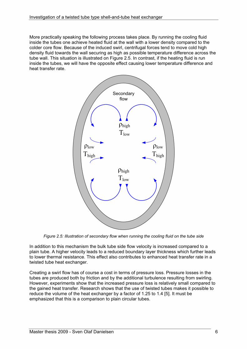
More practically speaking the following process takes place. By running the cooling fluid inside the tubes one achieve heated fluid at the wall with a lower density compared to the colder core flow. Because of the induced swirl, centrifugal forces tend to move cold high density fluid towards the wall securing as high as possible temperature difference across the tube wall. This situation is illustrated on Figure 2.5. In contrast, if the heating fluid is run inside the tubes, we will have the opposite effect causing lower temperature difference and heat transfer rate.
Secondaryflow
ρhigh
Tlow
ρlow
Thigh
ρhigh
Tlow
ρlow
Thigh
Figure 2.5: Illustration of secondary flow when running the cooling fluid on the tube side
In addition to this mechanism the bulk tube side flow velocity is increased compared to a plain tube. A higher velocity leads to a reduced boundary layer thickness which further leads to lower thermal resistance. This effect also contributes to enhanced heat transfer rate in a twisted tube heat exchanger. Creating a swirl flow has of course a cost in terms of pressure loss. Pressure losses in the tubes are produced both by friction and by the additional turbulence resulting from swirling. However, experiments show that the increased pressure loss is relatively small compared to the gained heat transfer. Research shows that the use of twisted tubes makes it possible to reduce the volume of the heat exchanger by a factor of 1.25 to 1.4 [5]. It must be emphasized that this is a comparison to plain circular tubes.
Investigation of a twisted tube type shell-and-tube heat exchanger
Master thesis 2009 - Sven Olaf Danielsen 7
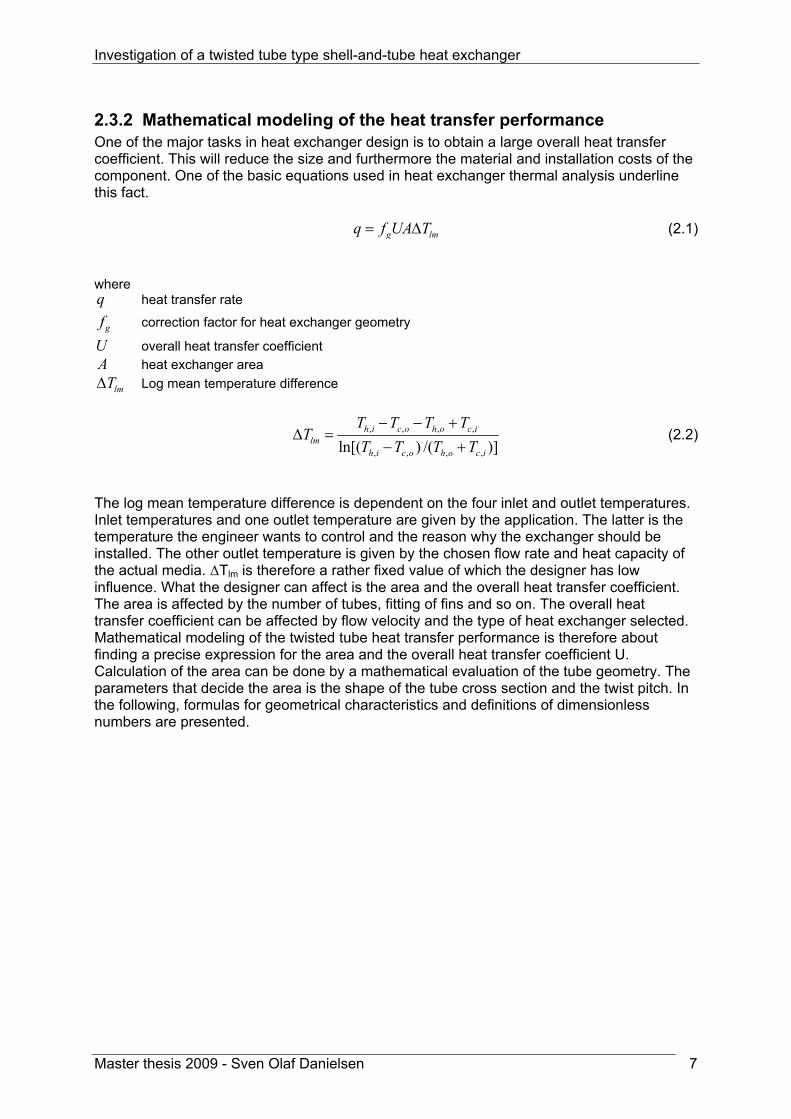
2.3.2 Mathematical modeling of the heat transfer performance One of the major tasks in heat exchanger design is to obtain a large overall heat transfer coefficient. This will reduce the size and furthermore the material and installation costs of the component. One of the basic equations used in heat exchanger thermal analysis underline this fact. g lmq f UA T= Δ (2.1) where q heat transfer rate
gf correction factor for heat exchanger geometry
U overall heat transfer coefficient A heat exchanger area
lmTΔ Log mean temperature difference
, , , ,
, , , ,ln[( ) /( )]h i c o h o c i
lmh i c o h o c i
T T T TT
T T T T− − +
Δ =− +
(2.2)
The log mean temperature difference is dependent on the four inlet and outlet temperatures. Inlet temperatures and one outlet temperature are given by the application. The latter is the temperature the engineer wants to control and the reason why the exchanger should be installed. The other outlet temperature is given by the chosen flow rate and heat capacity of the actual media. ΔTlm is therefore a rather fixed value of which the designer has low influence. What the designer can affect is the area and the overall heat transfer coefficient. The area is affected by the number of tubes, fitting of fins and so on. The overall heat transfer coefficient can be affected by flow velocity and the type of heat exchanger selected. Mathematical modeling of the twisted tube heat transfer performance is therefore about finding a precise expression for the area and the overall heat transfer coefficient U. Calculation of the area can be done by a mathematical evaluation of the tube geometry. The parameters that decide the area is the shape of the tube cross section and the twist pitch. In the following, formulas for geometrical characteristics and definitions of dimensionless numbers are presented.

Investigation of a twisted tube type shell-and-tube heat exchanger
Master thesis 2009 - Sven Olaf Danielsen 8
Geometrical formulas for twisted tube Flow area of a twisted tube can be calculated by use of the formula for the area of an ellipse. With our terminology the formula for flow area becomes following.
,max ,min4flow in inA d dπ= (2.3)
The perimeter of an ellipse can only be represented exact by a mathematical series. However, the Indian mathematician S. Ramanujan has developed a very accurate formula for determination of perimeter length [7]. ,max ,min ,max ,min ,max ,min[3( ) (3 )( 3 )]in in in in in inP d d d d d dπ= + − + + (2.4)
By use of the general formula for hydraulic diameter 4 /hD A P= [8], equation (2.3) and (2.4) one arrives at the following expression for the twisted tube hydraulic diameter
,max ,min
,max ,min ,max ,min ,max ,min3( ) (3 )( 3 )in in
hin in in in in in
d dd
d d d d d d=
+ − + + (2.5)
Correlations for thermal-hydraulic characteristics are found by the performed literature study. In the correlations an efficient diameter de is used. None of the sources give a clear definition of this parameter. Some sources [9], which not give the correlations, claim that the hydraulic and the efficient diameter are two different parameters. By investigating known formulas in the sources were the efficient diameter is used, it is concluded that this parameter is equal to the hydraulic diameter.

Investigation of a twisted tube type shell-and-tube heat exchanger
Master thesis 2009 - Sven Olaf Danielsen 9
Dimensionless numbers used in the correlations Correlations for thermal-hydraulic characteristics are often given as a function of dimensionless numbers. These numbers are presented here starting with the Nusselt number.
h
c
hdNuk
= (2.6)
The correlations for Nusselt number are valid for a certain range of Reynolds number defined by
Re hvdρμ
= (2.7)
and a function of the Prandtl number
Prc
Cpkμ
= (2.8)
and the dimensionless swirl number
2
max h
sFrd d
= (2.9)
The dimensionless swirl number is a clever way to represent swirl which contain dmax and dh. By involving both dmax and dh the dimensionless swirl number not only gives information on degree of twisting, but also the shape of oval cross section. As the difference between dmax and dh get smaller, the oval cross section will approach a circular shape. The structure of the number also implies that for the same twist pitch s, one can have different values of the dimensionless swirl.

Investigation of a twisted tube type shell-and-tube heat exchanger
Master thesis 2009 - Sven Olaf Danielsen 10
Determination of the heat transfer coefficient U Here an expression for the local heat transfer coefficient is developed. The case considered below is simplified due to the assumption of equal surface area on shell side and tube side. However, the derivation below shows the idea of the overall heat transfer coefficient. In thermal analysis an analogy to electricity is often used. The temperature difference has the role as voltage, which is the driving force for exchanging heat. Thus heat has taken the role as current flowing form high temperature (potential) to low temperature (potential). Fluids and materials reduce the heat transfer rate by acting as thermal resistances. The equation and illustration below explains the idea.
totT R qΔ = (2.10)
Figure 2.6: Thermal resistance The illustration below shows the three thermal layers where the heat transfer occurs in the heat exchanger. By use of the figure an expression for the local heat transfer coefficient can be determined.
Figure 2.7: Illustration of heat transfer in a heat exchanger
Rtot
TH
TL
q

Investigation of a twisted tube type shell-and-tube heat exchanger
Master thesis 2009 - Sven Olaf Danielsen 11
The derivation starts with the following equation describing the total temperature difference over the thermal layers. The temperatures are a function of x along the axial axis of the heat exchanger.
''( )
, ( ) , ( )( )
xb s x b t x
x
qT T
U− = (2.11)
Each layer can be described mathematically by the individual temperature difference. The shell-side convection is modeled by ''
( ) , ( ) , ( )( )x s b s x w s xq h T T= − (2.12) The conduction through the tube
''( ) , ( ) , ( )( )cx w s x w t x
kq T TL
= − (2.13)
And the tube-side convection ''
( ) , ( ) , ( )( )x t w t x b t xq h T T= − (2.14)
Reorganizing equation (2.12), (2.13) and (2.14) with respect to temperature difference and summing up the left and right hand side give
'', ( ) , ( ) ( )
1 1( )tb s x b t x x
s c t
LT T qh k h
− = + + (2.15)
When one compare equation (2.11) to (2.15) it is clear that
1( )
1 1( )tx
s c t
LUh k h
−= + + (2.16)
The result above is applicable for a clean heat exchanger. In addition one has to take account for fouling on the tube inner and outer surface. This layer will act as a thermal resistant and is accounted for in one parameter Rf despite the fact that fouling may occur on both shell side and tube side. If this parameter is included the following expression for local heat transfer coefficient can be written valid for equal heat transfer area on shell and tube side.
1( )
1 1( )tx f
s c t
LU Rh k h
−= + + + (2.17)

Investigation of a twisted tube type shell-and-tube heat exchanger
Master thesis 2009 - Sven Olaf Danielsen 12
Figure 2.8 shows how U(x) can be represented by a thermal circuit with resistances.
Figure 2.8: Heat transfer between the two fluids represented by thermal resistances.
In the application of heat exchangers the overall heat transfer coefficient U, must be derived on the basis of either the tube side or the shell side surface area. The determination of the twisted tube area is very complex to solve analytically because the perimeter length of an ellipse can only be calculated by mathematical series. Calculation of the area is not performed here. However the area can be determined numerically by a computer program. Computer software for heat exchanger design determines both the area and the overall heat transfer coefficient. In order to achieve accurate heat transfer calculations the software need to use correlations for the convective heat transfer coefficients. Correlations for the shell side and tube side convection coefficients in twisted tube heat exchangers are presented in the following introduced by a section about temperature influence on fluid properties.
Investigation of a twisted tube type shell-and-tube heat exchanger
Master thesis 2009 - Sven Olaf Danielsen 13
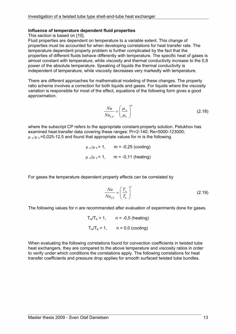
Influence of temperature dependent fluid properties This section is based on [10]. Fluid properties are dependent on temperature to a variable extent. This change of properties must be accounted for when developing correlations for heat transfer rate. The temperature dependent property problem is further complicated by the fact that the properties of different fluids behave differently with temperature. The specific heat of gases is almost constant with temperature, while viscosity and thermal conductivity increase to the 0,8 power of the absolute temperature. Speaking of liquids the thermal conductivity is independent of temperature, while viscosity decreases very markedly with temperature. There are different approaches for mathematical modeling of these changes. The property ratio scheme involves a correction for both liquids and gases. For liquids where the viscosity variation is responsible for most of the effect, equations of the following form gives a good approximation.
m
w
CP b
NuNu
μμ
⎛ ⎞= ⎜ ⎟⎝ ⎠
(2.18)
where the subscript CP refers to the appropriate constant-property solution. Petukhov has examined heat-transfer data covering these ranges: Pr=2-140; Re=5000-123000; μ w/μ b =0,025-12,5 and found that appropriate values for m is the following.
μ w/μ b > 1, m = -0,25 (cooling)
μ w/μ b < 1, m = -0,11 (heating) For gases the temperature dependent property effects can be correlated by
n
w
CP b
TNuNu T
⎛ ⎞= ⎜ ⎟⎝ ⎠
(2.19)
The following values for n are recommended after evaluation of experiments done for gases.
Tw/Tb > 1, n = -0,5 (heating)
Tw/Tb < 1, n = 0,0 (cooling) When evaluating the following correlations found for convection coefficients in twisted tube heat exchangers, they are compared to the above temperature and viscosity ratios in order to verify under which conditions the correlations apply. The following correlations for heat transfer coefficients and pressure drop applies for smooth surfaced twisted tube bundles.

Investigation of a twisted tube type shell-and-tube heat exchanger
Master thesis 2009 - Sven Olaf Danielsen 14
Shell side convection coefficient Correlations for shell side convection coefficient is based on [4]. The following correlations for convection coefficients are found experimentally by the russian researcher B.V Dzyubenko. He used electricity to heat the twisted tubes. The heated fluid was air flowing on the shell side of the test unit. The following correlations are therefore valid for heating of the shell side fluid. For developed turbulent flow (x/dh > 14) experiments resulted in the following expressions for the shell side convection coefficient.
,0,8 0,4 0,357 0,55( ),
,
0,0023Re Pr [1 3,6 ]( )w sx s
b s
TNu Fr
T− −= + (2.20)
For Fr = 232 – 2440
,0,8 0,4 0,55( ),
,
0,0521Re Pr ( )w sx s
b s
TNu
T−= (2.21)
For Fr = 64 For developing turbulent flow (x/dh < 14) Dzyubenko came to the following result for shell side convection
,1,2 0,4 0,55( ), 0,357
3,683,5 Re Pr ( ) [1 ]w snx s
b
TNu Fr
T Fr− −= + (2.22)
where the exponent n for FrM < 924 0,1940, 212n Fr=
FrM > 924 0,8n = It is observed that the temperature ratio exponents in (2.20), (2.21) and (2.22) are in agreement with the value -0,5 recommended for n in equation (2.19). In the scientific article ”Testing of Twisted-Tube Exchangers in Transition Flow Regime” by Blazo Ljubicic it is described how experiments are done at the Heat Transfer Research Incorporated testing facility. The experimental set up, a closed loop system, included three twisted-tube exchangers in series. One exchanger operated as a heater, the second as a cooler while the third exchanger operated as an inter-changer. The test fluid circulated on the shell-side in all exchangers, and the service fluids, condensing steam and cooling water, circulated through the tubes. The experiments resulted in the following general correlation for the shell side convective heat transfer coefficient [3].
31 0,4 0,14( ), / Re Pr ( )mm bx s h c
w
Nu C μμ
= ⋅ ⋅ Φ ⋅ (2.23)
where Ch/c Two different constants depending if the shell side fluid is heated or cooled Φ Swirl flow parameter
/b wμ Viscosity in the bulk flow and at the wall respectively

Investigation of a twisted tube type shell-and-tube heat exchanger
Master thesis 2009 - Sven Olaf Danielsen 15
The Reynolds number and swirl flow exponents are unfortunately not given in the article. While Dzyubenko states that his correlation apply for heating of gases, Ljubicic does not specify the application of correlation (2.23). By comparing this equation to the temperature and viscosity ratios in (2.18) and (2.19) it is concluded that the Ljubicic equation applies for heating of liquids on the shell side of twisted tube heat exchangers. Tube side convection coefficient The article “Coefficients of Heat Transfer and Hydraulic Drag of a Twisted Oval Tube” by L. A. Asmantas investigates both tube side heat transfer and pressure drop. By analyzing data from tests done on tubes with a twist pitch of 6,2 and 12,2 the researchers ended up with the following tube side heat transfer correlation
,0,8 0,4 1( ), max
,
0,021Re Pr [1 3,74( / ) ]( )w t nx t
b t
TNu s d
T−= ⋅ + (2.24)
where
5 1,37 2,10,17 0,27 10 ( / ) [( / ) 109,6]n x d s d−= − − ⋅ − and x denotes the distance from the tube entrance. Since the temperature ratio is present in (2.24) it applies for gases and not for liquids. It is not specified in the article whether the correlation holds for heating or cooling. Equation (2.20), (2.21), (2.22), (2.23) and (2.24) are correlations for the local Nusselt number being a function of x. In order to find the average Nusselt number one must both integrate the equation over the tube length L and divide the result with the same parameter. The conversion from local to average Nusselt number can be done by solving the following integral.
( )0
1 L
av xx
Nu Nu dxL =
= ∫ (2.25)
For comparison tube side Nusselt number for a circular tube is also presented here. The following equation is developed by Sieder and Tate for turbulent tube flow[11].
0,14
4/5 1/3( ), 0,027 Re Pr bx t
w
Nu μμ
⎛ ⎞= ⋅ ⎜ ⎟
⎝ ⎠ (2.26)
valid for 0,7 < Pr <16000 ReD > 10000 L/D > 10

Investigation of a twisted tube type shell-and-tube heat exchanger
Master thesis 2009 - Sven Olaf Danielsen 16
2.3.3 Mathematical modeling of the pressure drop The pressure drop in a heat exchanger is an important concern. In heat exchanger design a high pressure drop result in a higher required pump power leading to increased operation costs. In addition the heat transfer rate can be influenced significantly by the saturation temperature change for a condensing/evaporating fluid if there is a large pressure drop associated with the flow. This is due to the fact that saturation temperature changes with differences in saturation pressure and in turn affects the temperature potential for heat transfer. There are two main contributions to the pressure drop: pressure drop associated with the core and pressure drop associated with fluid distribution devices such as inlet/outlet headers, manifolders, tanks, nozzles, ducting and so on. The task of the heat exchanger is to transfer heat from one fluid to another. It must be a certain pressure drop present in order to force the fluid past the heat exchanging surface. Therefore most of the pressure drop available should be utilized in the heat exchanger core. The total heat exchanger pressure drop can be described as follows. total entrance core exitp p p pΔ = Δ + Δ + Δ (2.27) The calculation of entrance and exit pressure drop can be done in the same manner as for a conventional shell and tube heat exchanger. Since this report investigates twisted tube bundles in particular only the core pressure drop will be considered here. The pressure loss in a pipe/duct can be generally described in terms of Darcys friction factor [8].
2
2core Dh
Lp f vd
ρΔ = (2.28)
where fD Darcy friction factor L tube length dh hydraulic diameter ρ fluid density v bulk velocity The challenge when performing pressure drop predictions is to develop an accurate expression for the friction factor. For circular tubes one can extract fD from the famous Moody chart when the wall roughness is known. This chart does not apply to the twisted tube or the complex shaped ducts formed in the inter-tubular space. The correlation for the friction factor must therefore be developed on the basis of experiments done on twisted tube bundles.

Investigation of a twisted tube type shell-and-tube heat exchanger
Master thesis 2009 - Sven Olaf Danielsen 17
Shell side friction coefficient The hydraulic characteristics of twisted tube bundles have been investigated by the researcher B.V. Dzyubenko. Analysis of experimental data show that
0,25 0,357
0,3164 3,6[1 ]ReDf Fr
= + (2.29)
For Fr > 100 0,25 6 0,380,3164Re (1 3,1 10 )Df Fr− −= + ⋅ (2.30) For Fr < 100 Correlation (2.29) and (2.30) are based on experiments that was performed on bundles with 9 and 37 tubes respectively. Therefore a significant contribution to the friction loss is associated with friction against the shell wall. Of this reason these two correlations apply best to bundles with few tubes were shell wall friction make a considerable contribution to the pressure drop. Based on the same experiments a third expression is developed. This correlation applies for the friction factor in larger bundles containing more tubes. One ends up with the following correlation for the shell wall friction. 1,6181 0,263log10,5 Fr
Df Fr− += (2.31)
For 64 < Fr < 1052 Tube side friction coefficient Tube side pressure loss is investigated by L.A. Asmantas in an article “Coefficients of Heat Transfer and Hydraulic Drag of a Twisted Oval Tube” [5]. By use of his own experiments and analyzing the data a correlation for the tube side pressure loss was found. 0,55 0,180,92( / ) ReD hf s d − −= (2.32)
It is emphasized in the article that this friction factor not only includes pressure drop in the heat exchanger core flow, but also pressure losses at the inlet and exit from the twisted oval tube. This loss contribution is estimated to be from 10 to 16 percent. In other words the pressure loss is claimed to be somewhat lower in the heat exchanger core than actually predicted with this correlation. The swirl is here represented by the ratio s/dh. For comparison a correlation for turbulent flow in plain circular tubes are also presented here. In 1939 Colebrook combined two pipe flow correlations for smooth and rough wall. This clever combination resulted in an implicit formula that the Moody chart is based on [8].
1/ 2 1/ 2
1 / 2,512,0 log3,7 ReD d
df f
ε⎛ ⎞= − +⎜ ⎟
⎝ ⎠ (2.33)

Investigation of a twisted tube type shell-and-tube heat exchanger
Master thesis 2009 - Sven Olaf Danielsen 18
2.4 Fouling and determination of fouling resistance Rf This section is based on [12].
2.4.1 Fouling in general Fouling is accumulation of unfavorable material on the heat exchanging surface. The layer can consist of crystals, sediments, rust or other substances. Fouling has two effects on the heat exchanger performance. Because the fouling layer acts as a thermal resistant, overall heat transfer coefficient will be reduced. The second effect arise from changes on the heat exchanging surface and the reduced flow area which translate into increased pressure loss. Fouling is also costly. Because it is unpredictable heat exchangers are often oversized in the design process. This means that more material and space is used in the design than necessary. In addition, fouling generates cost from cleaning and the associated loss in production. The most important parameters that affect fouling are
• The nature of the flowing fluid, clean or dirty • Flow velocity • Flow temperature • Material of construction and surface finish
The nature of the flowing fluid has large influence on an eventual development of a fouling layer. Typically a pollution free, clean fluid like steam will not form a fouling layer while heavy hydrocarbon streams foul readily and affect the thermal hydraulic performance. The choice of fluids is often given by the application and therefore in most cases the designer cannot influence this parameter. Flow velocity has an important impact on fouling. When the flow velocity is increased the viscous sub layer close to the wall gets thinner resulting in lower resistance to diffusion from the bulk to the wall. This effect of increased velocity will tend to promote fouling. At the same time higher velocity increases the shearing forces that remove the fouled deposit. The net rate of fouling will therefore be a sum of these two opposing effects. Because the shear forces tend to increase more than the diffusion from the bulk to the wall, higher flow velocity invariably result in less fouling. The rates of chemical reaction are a strong function of temperature. Therefore, for fouling processes caused by chemical reactions, temperature will have an important impact on the extent of fouling. Corrosion is a typical example of a chemical reaction that will be affected by temperature. Bio-fouling is also dependent on the temperature. At higher temperatures, the rates of chemical and enzyme reactions increase due to increased cell growth rate. However, there will be an upper and lower temperature limit in which a specific organism can survive. The roughness, size, and density of cavities affect crystalline nucleation, sedimentation and the sticking tendency of deposits. Smooth surfaces have properties that make the surface less likely to receive and retain dirt than rough surfaces. Practical experience shows that smooth surfaces tend to foul less.

Investigation of a twisted tube type shell-and-tube heat exchanger
Master thesis 2009 - Sven Olaf Danielsen 19
2.4.2 Fouling in twisted tube heat exchangers In a conventional shell and tube heat exchanger the fluid is directed perpendicular to the tubes by baffles. The shell side fluid has to make turns around each baffle which is illustrated below. Due to the turning, flow velocity is lower at the outer curve than at the inner curve resulting in an uneven flow distribution. Uneven flow distribution is unfavourable because such flow may contain dead spots were the velocity is very low. As mentioned in the previous section the risk of fouling is increased at locations were the velocity is low and where extreme temperatures arise.
Figure 2.9: Shell side flow pattern in a conventional shell and tube
The illustration below shows the shell side flow pattern on a twisted tube heat exchanger. Because the flow is evenly distributed on the cross section and not forced to do turns, one achieve a uniform flow without dead spots. The twisted tube also has and advantage on tube side fouling. Increased turbulence and absolute velocity result in less risk of fouling inside the twisted tubes compared to plain tubes.
Figure 2.10: Shell side flow pattern in a twisted tube
2.4.3 Fouling resistance Rf Prediction of the fouling factor Rf is a part of the calculation process for the overall heat transfer coefficient. The thermal resistance caused by fouling can be determined either by mathematical models or empirical data. The vendor use the discussion presented in section 2.4.2 to explain how the twisted tube is less exposed to fouling compared to the conventional alternative. How a twisted tube heat exchanger performs in terms of fouling can be evaluated by investigation of the overall heat transfer coefficient. In Chapter 5 the fouling tendency is investigated by analyzing measurements performed on a twisted tube heat exchanger in operation. How the twisted tube performs compared to other heat exchanger designs is discussed in Chapter 6.

Investigation of a twisted tube type shell-and-tube heat exchanger
Master thesis 2009 - Sven Olaf Danielsen 20
2.5 Flow induced vibration
2.5.1 Flow induced vibration in heat exchangers This section is based on [12]. Consideration of tube vibration is an important concern when designing a shell-and-tube heat exchanger. Many exchangers have failed as a result of flow induced vibrations. A good example is the vibration problems that StatoilHydro face on their LNG production facility at Hammerfest, Norway. Heat exchanger tubes often vibrate, but at such low frequencies that there is no damage. The lowest frequency at which tubes vibrate is the natural frequency. Higher natural frequencies are known as the second mode, third mode, and so on. The natural frequency depends on a number of factors.
• the way they are fixed • the nature of the intermediate supports • the length of the unsupported span • number of spans • tube material and thickness
The following formula for prediction of the natural frequency is developed by MacDuff and Felgar.
40,04944n ne un
EIgf CW L
= (2.34)
where fn natural frequency of straight tubes Cn frequency constant E modulus of elasticity I sectional moment of inertia g gravitational constant We effective weight per unit tube length including the weight of the fluid inside tubes Lun tube unsupported span Investigating the above equation one observe that some parameters have more influence on the tube natural frequency than others. While the frequency depends on the unsupported span in the power of two, the other equation parameters influence the natural frequency in the power of 0,5. It means that the only parameter left than can be controlled and affect the natural frequency is the unsupported span. The tube vibration phenomena are vortex shedding, turbulent buffeting, and fluidelastic whirling. These phenomena have in common that they generate pressure variations at certain frequencies. The frequencies depend on parameters such as cross flow velocity and tube diameter. If one of these frequencies is equal to the tube natural frequency there is a high probability for resonance, leading to severe tube vibration. Such vibration will with time lead to a failure in one or several tubes. The most common reasons are rupture caused by interaction between tubes and baffles, but fatigue and tube joint leakage is also frequently experienced. By prediction of the natural frequency and the vibration frequencies one can prevent failure caused by flow induced vibration. If the vibration frequencies are close to the natural

Investigation of a twisted tube type shell-and-tube heat exchanger
Master thesis 2009 - Sven Olaf Danielsen 21
frequency it is necessary to reduce the unsupported span of the tubes. This will solve the problem because the natural frequency increases more than the vibration frequencies.
2.5.2 Reduced risk for flow induced vibration in twisted tube bundles Based on the theory for flow induced vibration presented in the previous section, one can qualitatively compare the twisted tube heat exchanger to baffle based designs. The most important point is that the twisted tube bundle is a very rigid construction. Each tube is supported by the adjacent tubes six times per 360 degree twist. Consideration of a twisted tube with a twist pitch to diameter ratio equal to 6 and an outer diameter of 24mm will give an unsupported span of 24mm. A conventional shell and tube exchanger will typically have a baffle spacing of 500mm. By strengthening the bundle with 4 support baffles per baffle set and choosing a no tubes in window configuration result in an unsupported tube span of 100mm. Even by using such design tools to prevent vibration in the conventional design the span is larger than for the twisted tube by a factor of four. Using equation (2.34) this translates into a difference in natural frequency by a factor sixteen in favour of the twisted tube. This example illustrates the stiffness of a twisted tube bundle. In addition to the reduced unsupported span, the twisted tube design has one more feature that is advantageous with respect to vibrations. All the flow induced vibration phenomena is dependent on a flow velocity perpendicular to the tubes. Since the shell side flow is in the axial direction of the twisted tubes there is no basis for these phenomena to grow in strength and to increase frequency. Summarized the twisted tube is less subject to vibration problems because of the stiffness of the bundle and the flow direction on the shell side. Therefore the vendors of these heat exchangers can claim that the design is vibration free.

Investigation of a twisted tube type shell-and-tube heat exchanger
Master thesis 2009 - Sven Olaf Danielsen 22
2.6 Applications The twisted-tube exchanger meets the requirements of the design codes TEMA and API 660. It can therefore in most cases be used as a replacement for the conventional shell-and-tube exchanger. In addition the twisted-tube has features this far only found in plate exchangers, and can therefore to some extent replace this type of heat exchangers. Several hundred twisted-tube exchangers have been manufactured since 1984 for various applications. The table below show which industries that have been provided with twisted tube solutions.
Industry ApplicationChemical Sulphuric acid cooling
Ammonia preheatingHydrogen peroxide cooling/heating
Petroleum High pressure gas heating/coolingOil heatingBitumen heatingLNG heating
Pulp & paper Black liquor heating/coolingWhit water coolingOil heating/coolingEffluent cooling
Power Turbine steam condensingBoiler feedwater heatingLube oil cooling
Steel Quench oil coolingLube oil coolingCompressed gas cooling
Mining & mineral processing Liquor coolingEffluent cooling
District heating Closed loop water heatingSteam heaters
Table 2.1: List of twisted tube deliveries [13]

Investigation of a twisted tube type shell-and-tube heat exchanger
Master thesis 2009 - Sven Olaf Danielsen 23
2.7 Industrial experience, operation and maintenance This section is based on reference [14] and [1]. The information is found on Siljan Allards and Koch Heat Transfer web sites respectively. When reading the following one must keep in mind that the text is based on information provided by the vendors of the twisted tube heat exchanger. The statements may be coloured by their incentives to sell this type of equipment.
2.7.1 Industrial experience The Swedish company Siljan Allards AB has produced twisted tube heat exchangers since the beginning of 1980’s. Siljan Allards name their concept Alfatwist. In total 700 exchangers of this type has been delivered to the power, paper, chemical, pharmaceutical and food manufacturing industry. Siljan Allards claim a very high customer satisfactory due to reduction of fouling and elimination of vibration problems. As an example the Swedes mention a delivery to a large vehicle plant. They had substantial problems with fouling on the tube side of heat exchangers with plain tubes. After installation of twisted tube heat exchangers, the fouling problem was reduced due to intensification of the tube side turbulence. In the same reference list it is mentioned a twisted tube exchanger that replaced a shell and tube heat exchanger in 1983 due to vibration problems. The twisted tube exchanger still operates 24 years later when the reference list was written in December 2007. Siljan Allards has many of these success stories to tell about their Alfatwist concept. In addition to a vibration free concept the vendors claim that the heat exchanger has higher heat transfer performance and lower pressure drop than a conventional shell and tube. These statements will be investigated by use of measured data and the computer program HTRI in Chapter 6, page 56.
2.7.2 Cleaning Cleaning may be performed on the heat exchanger in place. Chemical cleaning in place is claimed to be more effective in twisted tube heat exchangers than in conventional shell and tube due to uniform flow distribution and swirl flow. Another way of doing maintenance is by removing the twisted tube bundle from the outer shell. Lanes formed by the tubes allow complete mechanical cleaning by hydro blasting on the shell side. This may be more difficult for a conventional shell and tube because the tubes will form a wall such that the core tubes are not cleaned. The tube side in a twisted tube can also be cleaned effectively by hydro blasting due to the induced swirl flow and high turbulence.
Investigation of a twisted tube type shell-and-tube heat exchanger
Master thesis 2009 - Sven Olaf Danielsen 24
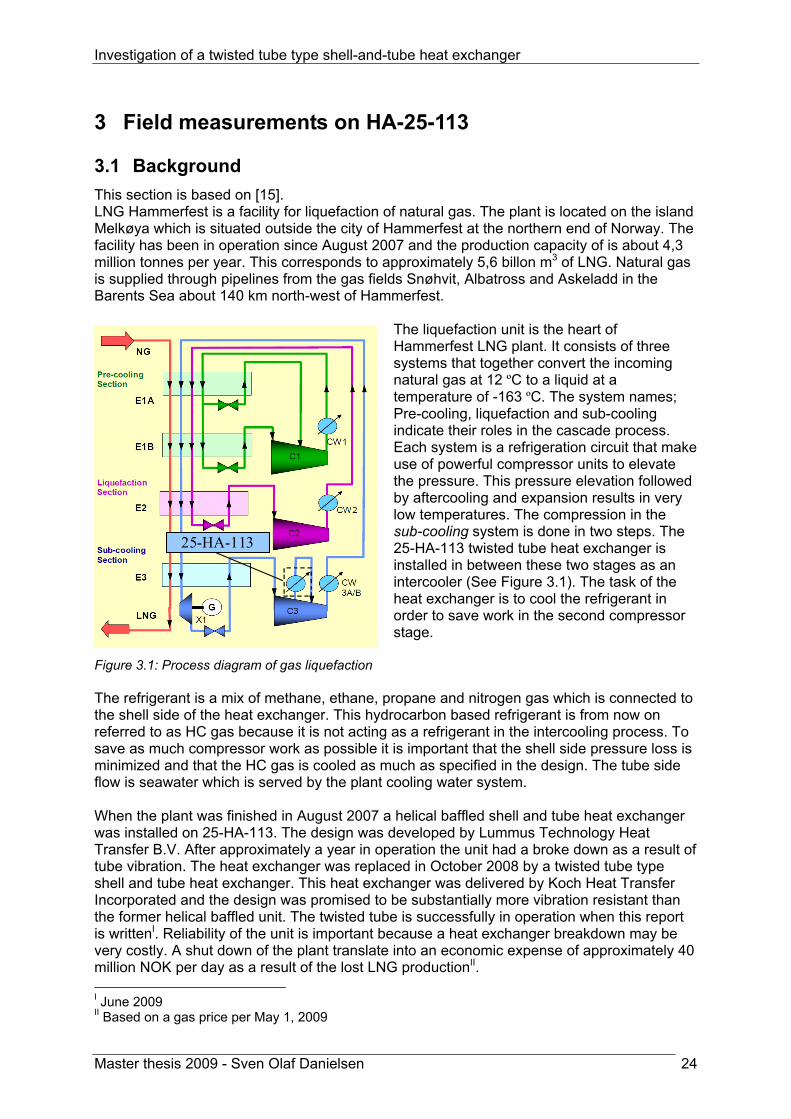
3 Field measurements on HA-25-113 3.1 Background This section is based on [15]. LNG Hammerfest is a facility for liquefaction of natural gas. The plant is located on the island Melkøya which is situated outside the city of Hammerfest at the northern end of Norway. The facility has been in operation since August 2007 and the production capacity of is about 4,3 million tonnes per year. This corresponds to approximately 5,6 billon m3 of LNG. Natural gas is supplied through pipelines from the gas fields Snøhvit, Albatross and Askeladd in the Barents Sea about 140 km north-west of Hammerfest.
The liquefaction unit is the heart of Hammerfest LNG plant. It consists of three systems that together convert the incoming natural gas at 12 ºC to a liquid at a temperature of -163 ºC. The system names; Pre-cooling, liquefaction and sub-cooling indicate their roles in the cascade process. Each system is a refrigeration circuit that make use of powerful compressor units to elevate the pressure. This pressure elevation followed by aftercooling and expansion results in very low temperatures. The compression in the sub-cooling system is done in two steps. The 25-HA-113 twisted tube heat exchanger is installed in between these two stages as an intercooler (See Figure 3.1). The task of the heat exchanger is to cool the refrigerant in order to save work in the second compressor stage.
Figure 3.1: Process diagram of gas liquefaction The refrigerant is a mix of methane, ethane, propane and nitrogen gas which is connected to the shell side of the heat exchanger. This hydrocarbon based refrigerant is from now on referred to as HC gas because it is not acting as a refrigerant in the intercooling process. To save as much compressor work as possible it is important that the shell side pressure loss is minimized and that the HC gas is cooled as much as specified in the design. The tube side flow is seawater which is served by the plant cooling water system. When the plant was finished in August 2007 a helical baffled shell and tube heat exchanger was installed on 25-HA-113. The design was developed by Lummus Technology Heat Transfer B.V. After approximately a year in operation the unit had a broke down as a result of tube vibration. The heat exchanger was replaced in October 2008 by a twisted tube type shell and tube heat exchanger. This heat exchanger was delivered by Koch Heat Transfer Incorporated and the design was promised to be substantially more vibration resistant than the former helical baffled unit. The twisted tube is successfully in operation when this report is writtenI. Reliability of the unit is important because a heat exchanger breakdown may be very costly. A shut down of the plant translate into an economic expense of approximately 40 million NOK per day as a result of the lost LNG productionII. I June 2009 II Based on a gas price per May 1, 2009
25-HA-113

Investigation of a twisted tube type shell-and-tube heat exchanger
Master thesis 2009 - Sven Olaf Danielsen 25
3.2 Koch twisted tube solution Koch Heat Transfer Inc. has supplied the twisted tube heat exchanger solution. A design basis was handed over to their engineers so they could develop the design. This design basis can be found in PIMIII on document number E066-AB-P-DP-2546 [16] and technical drawings of the twisted tube solution can be found in Appendix E. The result of the design process was the heat exchanger described below. Baffle type: none Tube type: twisted Twist pitch: unknown dmax/dmin: unknown Bundle material: titanium
III See Abbreviations p.xviii

Investigation of a twisted tube type shell-and-tube heat exchanger
Master thesis 2009 - Sven Olaf Danielsen 26
Figure 3.2: TEMA specification sheet for Koch twisted tube design printed from HTRI

Investigation of a twisted tube type shell-and-tube heat exchanger
Master thesis 2009 - Sven Olaf Danielsen 27
3.3 Automatically logged measurements on 25-HA-113 The LNG Hammerfest plant is monitored continuously from the control room at the site. Hundreds of installed thermometers, pressure transducers and flow meters make sure that the operators are well informed about the state in the process at all times. Each unit perform measurements at a certain frequency that is saved electronically in a database. In this way the entire plant process history is available for evaluation and analysis. On 25-HA-113 there are several thermometers installed at the HC gas inlet and outlet. Pressure of the HC gas is measured by two pressure transducers on the inlet and outlet respectively while HC gas flow is measured by a flow meter based on the venturi principle. In order to determine the heat exchanger duty it is also necessary to know the gas composition. This is measured by gas chromatography. Physical properties of the HC gas are then calculated by use of the GERG08 which is a highly accurate equation of state. Heat exchanger duty can then be determined by the calculated enthalpy and the measured flow. The seawater temperatures are also logged, but no flow meter is installed on this side. However, seawater flow can be determined by the other measured quantities. This is simply done by a heat balance calculation dividing the duty by seawater temperature difference and specific heat capacity. It is important to keep in mind that the seawater flow is only a result of GERG08 property calculations and is not measured directly. Measurements used for the analysis of 25-HA-113 are performed from 26.october 2008 to 2.february 2009 and can be found in Appendix B. The table below show the installed equipment that collected data for the analysis performed in this master thesis.
Tag number Property Manufacturer Position25-TI-1799A Temperature ABB HC gas inlet25-TI-1799B Temperature ABB HC gas inlet25-TI-1799C Temperature ABB HC gas inlet25-TI-1573 Temperature ABB HC gas inlet25-TI-1330 Temperature ABB HC gas outlet25-TI-1431 Temperature ABB HC gas outlet25-TI-1039 Temperature ABB HC gas outlet55-TI-1049A Temperature ABB Seawater inlet85-TI-2011 Temperature ABB Seawater outlet85-PI-2013 Pressure ABB HC gas inlet85-PI-2014 Pressure ABB HC gas outlet25-FI-1416 Flow Dosch HC gas outlet25-FI-1308 Flow Dosch HC gas outlet25-AI-1387A1 CH4 content ABB HC gas closed loop25-AI-1387B1 C2H6 content ABB HC gas closed loop25-AI-1387C1 C3H8 content ABB HC gas closed loop25-AI-1387D1 N2 content ABB HC gas closed loop25-AI-1868A1 CH4 content ABB HC gas closed loop25-AI-1868B1 C2H6 content ABB HC gas closed loop25-AI-1868C1 C3H8 content ABB HC gas closed loop25-AI-1868D1 N2 content ABB HC gas closed loop
Table 3.1: List of sensors that collect measurement data used in this report

Investigation of a twisted tube type shell-and-tube heat exchanger
Master thesis 2009 - Sven Olaf Danielsen 28
Figure 3.3: Process arrangement around 25-HA-113
The illustration above shows the process arrangement around the twisted tube heat exchanger 25-HA-113. Flow measurements are performed at 25FI1416 down stream of compressor stage two. In some operation modes valve 25ZI1308 is open. The flow through 25-HA-113 is then equal to the sum of measured flows in both 25FI1416 and 25FI1308. StatoilHydro has performed an analysis on the energy balance by use of the computer program Hysys. It turns out that there is a deviation between the delivered compressor work from 25-KA-103 calculated by Hysys and the compressor work measured on the site. The flow measurement of HC gas is as already mentioned performed downstream of compressor stage two. StatoilHydro believe that a possible leakage in the closed valve 25ZI1308 may be the reason why the calculated work is not in agreement with measurements. A leakage here means that the flow of HC gas is actually larger through the first compressor stage and heat exchanger 25-HA-113 than measured by the flow meter. If such leakage flow is discovered it

Investigation of a twisted tube type shell-and-tube heat exchanger
Master thesis 2009 - Sven Olaf Danielsen 29
means that the heat exchanger duty is larger in reality than indicated by measured data. This is an additional uncertainty to the measurements. Analysis performed by Tor Erling Sandvik at StatoilHydro show that the leakage is 5-15 tonnes/hr. Considering an average flow measured through 25FI1416 of 524 tonnes/hr this leakage will result in a increased real flow and duty by maximum 2,9%. 3.4 Measurement uncertainty This section is based on [17] and [18]. Measurement of a physical quantity involves consideration of the associated uncertainty. Prediction of the uncertainty requires that a certain confidence interval is specified. The confidence interval depicts the probability of a measured value to be within an upper and a lower limit. Normally a confidence level of 95% is used in uncertainty analysis. Therefore this level of confidence is also chosen in the following evaluation.
3.4.1 The root sum square formula (RSS) A formula that is very often used in uncertainty analysis is the Root-Sum-Square (RSS). The derivation of this formula will be shortly presented here. We initiate the derivation by defining a general known mathematical function 1 2( , ,... )nF f x x x= (3.1) F is a function of the independent variables x1, x2, x3,….xn. These variables are the measured values. Because of uncertainties associated with the measurements there will be a deviation between the real value and the measured value denoted by Δx. These deviations will lead to a change in F denoted by ΔF. This can be mathematically described by 1 1 2 2( , ,... )n nF F f x x x x x x+ Δ = ± Δ ± Δ ± Δ (3.2) The right hand expression above can be developed by a Taylor series. Terms of higher order than one are neglected. Equation (3.2) can therefore be written as
1 2 1 21 2
( , ,... ) ......n nn
f f fF F f x x x x x xx x x∂ ∂ ∂
+ Δ = + ⋅Δ + ⋅Δ + + ⋅Δ∂ ∂ ∂
(3.3)
By subtraction of (3.3) by (3.1) one obtain
1 21 2
..... nn
f f fF x x xx x x∂ ∂ ∂
Δ = ⋅Δ + ⋅Δ + + ⋅Δ∂ ∂ ∂
(3.4)
The above expression will calculate the largest possible ΔF for the given measured parameters x1, x2, x3,….xn. This expression anticipates that all the measured values will contribute to either an increase or a decrease of ΔF. In reality the measurements will both give a positive and a negative contribution and thereby to some extent cancel each other. It has been shown that the right way to express ΔF as a function of Δx is the following.
22 2
1 21 2
..... nn
f f fF x x xx x x
⎛ ⎞⎛ ⎞ ⎛ ⎞∂ ∂ ∂Δ = ± ⋅Δ + ⋅Δ + + ⋅Δ⎜ ⎟⎜ ⎟ ⎜ ⎟∂ ∂ ∂⎝ ⎠ ⎝ ⎠ ⎝ ⎠
(3.5)
This is called the Root-Sum-Square formula and is a widely used in error analysis.

Investigation of a twisted tube type shell-and-tube heat exchanger
Master thesis 2009 - Sven Olaf Danielsen 30
3.4.2 Absolute error In measurement theory it is common to divide the measurement error into systematic and random error. The systematic error is the constant deviation from the true value for a repeated measurement done by the same operator under the same environmental conditions. The random error is by nature random and unpredictable. Typically random errors are round-off errors, operator errors and errors caused by small changes in environmental conditions. While determination of the systematic error requires analysis of the calibration procedure and equipment, calculation of the random error is a matter of statistical analysis. Absolute error is the true error that depends on both systematic and random error. Mathematically the relation between absolute, systematic and random error can be presented in the following way.
2 2x x xw B P= + (3.6)
where Wx absolute uncertainty Bx systematic uncertainty Px random uncertainty
3.4.3 Random error The random uncertainty is dependent on the standard deviation of the measurements, number of readings in the sample and the statistical Student`s t-distribution. Compared to the Normal distribution the Student’s t is a wide probability function that includes the uncertainty associated with small sample sizes. Because the sample sizes considered here are less than 30 the Student’s t is an appropriate probability distribution. The random error can be calculated with the following equation.
xx
SP tn
= ± (3.7)
where t value of Student’s t for 95% confidence interval and a certain sample size n sample size Sx standard deviation of the sample
1/ 22
1
( )( 1)
ni
xi
x xSn=
⎛ ⎞−= ⎜ ⎟−⎝ ⎠∑ (3.8)

Investigation of a twisted tube type shell-and-tube heat exchanger
Master thesis 2009 - Sven Olaf Danielsen 31
3.4.4 Systematic error The systematic uncertainty remains constant if the test is repeated under the same conditions. From a statistical point of view the systematic error is the constant deviation between the true value and the population mean. The population mean is the mean of an infinite sample size from the actual measurement set up. Systematic uncertainties include errors which are known or can be estimated but have not been eliminated through calibration or the measurement process itself. The most practical method of systematic error determination is by combining elemental uncertainties. Different types of elemental errors can be generated in each component in a measurement system. ASMEIV suggests grouping the elemental errors into five categories: calibration uncertainties, data-acquisition uncertainties, data-reduction uncertainties, uncertainties due to methods, and other uncertainties. Data-acquisition uncertainties need further explanation. This kind of uncertainty arises when a specific measurement is made. Among the errors produced is random variation of the measurand, installation effects such as meaurand loading, analog-to-digital converter uncertainties and uncertainties in recording or indicating devices. By using the elemental error approach the systematic error can be estimated by the following formula.
2 2 2 2 2x c da dr m oB B B B B B= + + + + (3.9)
where Bc calibration uncertainty Bda data-acquisition uncertainty Bdr data reduction uncertainty Bm method uncertainty Bo other uncertainties Manufacturers of the measuring equipment often provide information on the uncertainty, but not always in the desired form. It is common for manufacturers to supply the uncertainty descriptor called accuracy. This parameter normally includes error due to hysteresis, linearity and repeatability in addition to the assumption that the calibration is still valid. When this parameter is given it can be considered the systematic accuracy. This approach is conservative for two reasons. The accuracy is often based on a confidence higher than 95% and the repeatability error is included twice in the calculation. In the following analysis accuracy informed by the manufacturer is considered as the systematic accuracy.
IV See Abbreviation page xviii

Investigation of a twisted tube type shell-and-tube heat exchanger
Master thesis 2009 - Sven Olaf Danielsen 32
3.4.5 Temperature measurement uncertainty The systematic uncertainty associated with the temperature measurements can be found by use of the information provided in PIMV. According to document E066-AB-J-DT-0001 all temperature sensors have an accuracy which agrees with IEC 751 class A. This standard specifies a tolerance for absolute deviation depending on the measured temperature. Figure 3.4 show how the tolerance is determined.
Figure 3.4: Uncertainty classes for temperature measurement, IEC 75 [19]
Using the diagram one can see that the tolerance is low for class A. One has to distinguish between the HC gas outlet/seawater temperature (10 ºC ) and the HC gas inlet temperature (60 ºC ) measurement. The diagram gives the following values for the systematic uncertainty.
Bx(Th,o/Tc) = +/-0,20 ºC Bx(Th,i) = +/-0,30 ºC
The random uncertainty must also be determined in order to predict an absolute uncertainty value for temperature measurements. This is done by using equation (3.7) which includes the determination of standard deviation and student’s t distribution value. The measurand, in this case the temperature, will vary with time because the operation point is not completely stable. However, a reasonable assumption is that the operation point does not change within one minute. The standard deviation is calculated based on this assumption. Some sensors transmit measurements at a higher rate than others to the electronic database. Therefore the standard deviation will also vary among the temperature sensors. Investigation of the standard deviation to three different temperature sensors resulted in the following conservative value.
Sx= 0,30 ºC
V See Abbreviations p.xviii

Investigation of a twisted tube type shell-and-tube heat exchanger
Master thesis 2009 - Sven Olaf Danielsen 33
The sensors register at least six temperature readings per minute. These registrations result in five degrees of freedom. For a 95% confidence interval this translates into a specific value from the student’s t distribution[18].
t = 2,571 Using (3.7) one arrives at the following value for temperature random uncertainty.
Px= +/-0,31 ºC Now one can determine the absolute uncertainty Wx by putting the values for systematic and random uncertainty into equation (3.6). Two different values are calculated as the systematic uncertainty varies with the measured temperature. The calculated absolute uncertainties and other key parameters are presented in Table 3.2 below.
Parameter ValueSx 0,30 ºC
n 6t 2,57Bx 10ºC 0,20 ºCBx 60ºC 0,30 ºCPx 0,31 ºCWx 10ºC (+/-) 0,37 ºCWx 60ºC (+/-) 0,43 ºC
Table 3.2: Temperature measurement uncertainty
As indicated in Table 3.1 there are several sensors that measure the HC gas inlet/outlet temperatures. An average of these values is used. This will lower the systematic uncertainty from the values presented here. Because it is desirable to calculate the uncertainty in a conservative way it is decided to keep the numbers presented above.
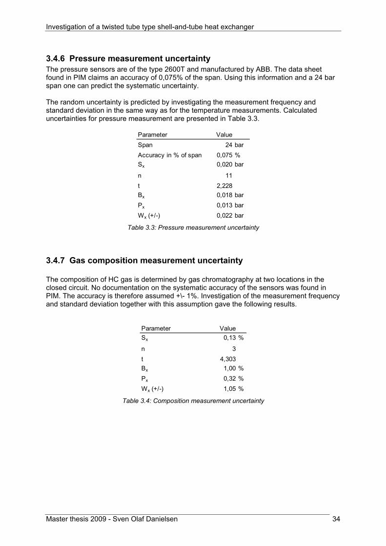
Investigation of a twisted tube type shell-and-tube heat exchanger
Master thesis 2009 - Sven Olaf Danielsen 34
3.4.6 Pressure measurement uncertainty The pressure sensors are of the type 2600T and manufactured by ABB. The data sheet found in PIM claims an accuracy of 0,075% of the span. Using this information and a 24 bar span one can predict the systematic uncertainty. The random uncertainty is predicted by investigating the measurement frequency and standard deviation in the same way as for the temperature measurements. Calculated uncertainties for pressure measurement are presented in Table 3.3.
Parameter ValueSpan 24 barAccuracy in % of span 0,075 %Sx 0,020 bar
n 11t 2,228Bx 0,018 barPx 0,013 barWx (+/-) 0,022 bar
Table 3.3: Pressure measurement uncertainty
3.4.7 Gas composition measurement uncertainty The composition of HC gas is determined by gas chromatography at two locations in the closed circuit. No documentation on the systematic accuracy of the sensors was found in PIM. The accuracy is therefore assumed +\- 1%. Investigation of the measurement frequency and standard deviation together with this assumption gave the following results.
Parameter ValueSx 0,13 %
n 3t 4,303Bx 1,00 %Px 0,32 %Wx (+/-) 1,05 %
Table 3.4: Composition measurement uncertainty
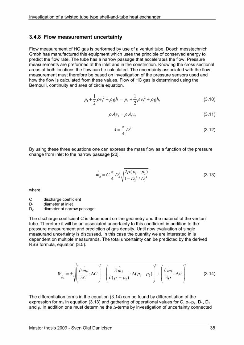
Investigation of a twisted tube type shell-and-tube heat exchanger
Master thesis 2009 - Sven Olaf Danielsen 35
3.4.8 Flow measurement uncertainty Flow measurement of HC gas is performed by use of a venturi tube. Dosch messtechnich Gmbh has manufactured this equipment which uses the principle of conserved energy to predict the flow rate. The tube has a narrow passage that accelerates the flow. Pressure measurements are preformed at the inlet and in the constriction. Knowing the cross sectional areas at both locations the flow can be calculated. The uncertainty associated with the flow measurement must therefore be based on investigation of the pressure sensors used and how the flow is calculated from these values. Flow of HC gas is determined using the Bernoulli, continuity and area of circle equation.
2 21 1 1 2 2 2
1 12 2
p v gh p v ghρ ρ ρ ρ+ + = + + (3.10)
1 1 2 2A v A vρ ρ= (3.11)
2
4A Dπ= (3.12)
By using these three equations one can express the mass flow as a function of the pressure change from inlet to the narrow passage [20].
2 1 22 4 4
2 1
2 ( )4 1 /h
p pm C DD D
ρπ −=
−
i (3.13)
where C discharge coefficient D1 diameter at inlet D2 diameter at narrow passage The discharge coefficient C is dependent on the geometry and the material of the venturi tube. Therefore it will be an associated uncertainty to this coefficient in addition to the pressure measurement and prediction of gas density. Until now evaluation of single measurand uncertainty is discussed. In this case the quantity we are interested in is dependent on multiple measurands. The total uncertainty can be predicted by the derived RSS formula, equation (3.5).
2 2 2
1 21 2
( )( )h
h h h
m
m m mW C p pC p p
ρρ
⎛ ⎞ ⎛ ⎞ ⎛ ⎞∂ ∂ ∂⎜ ⎟ ⎜ ⎟ ⎜ ⎟= ± ⋅Δ + ⋅Δ − + ⋅Δ⎜ ⎟ ⎜ ⎟ ⎜ ⎟∂ ∂ − ∂⎝ ⎠ ⎝ ⎠ ⎝ ⎠
i
i i i
(3.14)
The differentiation terms in the equation (3.14) can be found by differentiation of the expression for mh in equation (3.13) and gathering of operational values for C, p1-p2, D1, D2 and ρ. In addition one must determine the Δ-terms by investigation of uncertainty connected

Investigation of a twisted tube type shell-and-tube heat exchanger
Master thesis 2009 - Sven Olaf Danielsen 36
to C, ρ and p1-p2 to find the systematic uncertainty of the flow measurement. By using PIM and information on the operation point of the heat exchanger all necessary input were found. The results are presented in the table below.
Parameter ValueAccuracy C 0,05Accuracy p 375 PaAccuracy ρ 0,22 kg/m3
Differential C 145,60 kg/sDifferential p 0,00054 kg/sPaDifferential ρ 3,80 m3/sWx (+/-) 7,33 kg/s
Table 3.5: Flow measurement uncertainty
3.4.9 Duty measurement uncertainty The duty of the heat exchanger is not measured directly. It is determined by the mass flow rate of HC gas and the enthalpy which is calculated by GERG08 equation of state. , ,( )h h h i h oq m h h= − (3.15) The enthalpy is a function of temperature, pressure and gas composition. Using this information one can write the total uncertainty for the duty in the same manner as in equation (3.14)
2 22 2
h
h h h hhq h omp
h h omph
q q q qW m p T Cp T Cm
⎛ ⎞ ⎛ ⎞⎛ ⎞ ⎛ ⎞∂ ∂ ∂ ∂⎜ ⎟= ± ⋅Δ + ⋅Δ + ⋅Δ + ⋅Δ⎜ ⎟⎜ ⎟ ⎜ ⎟ ⎜ ⎟⎜ ⎟ ∂ ∂ ∂⎝ ⎠ ⎝ ⎠ ⎝ ⎠∂⎝ ⎠
i
i (3.16)
By using the thermodynamic properties in Appendix G one can calculate how enthalpy is affected by a change of pressure, temperature and composition. The term for HC gas mass flow rate can be determined by differentiating the duty with respect to mass flow rate.
Parameter ValueAccuracy 7,33 kg/sAccuracy p 2246 PaAccuracy T 0,43 ºCDifferential 110,09 kJ/kgDifferential p 0,01283 J/kgPaDifferential Th 1948,92 J/kgKWx (+/-) 807,04 kW
hm
hm
Table 3.6: Duty measurement uncertainty

Investigation of a twisted tube type shell-and-tube heat exchanger
Master thesis 2009 - Sven Olaf Danielsen 37
3.4.10 Overall heat transfer coefficient uncertainty The overall heat transfer coefficient is calculated by the duty, the heat transfer area and the log mean temperature difference. The geometry factor fg is assumed 1 for all calculations performed in this report. This may lead to a marginal error especially in Chapter 6, but the assumption is still used due to simplicity and to keep consistency in the calculations. The overall heat transfer coefficient is calculated by the following formula.
g lm
qUf A T
=Δ
(3.17)
Using (3.5) one arrives at the below expression for absolute uncertainty.
22 2 2
U lmlm
U U U UW q f A Tq f A T
⎛ ⎞⎛ ⎞ ⎛ ⎞∂ ∂ ∂ ∂⎛ ⎞= ± ⋅Δ + ⋅Δ + ⋅Δ + ⋅Δ⎜ ⎟⎜ ⎟ ⎜ ⎟ ⎜ ⎟∂ ∂ ∂ ∂Δ⎝ ⎠⎝ ⎠ ⎝ ⎠ ⎝ ⎠ (3.18)
By using this formula one arrive at the uncertainty presented in the table below.
Parameter ValueAccuracy q 817,44 kWAccuracy f 0,05Accuracy A 10,00 m2
Accuracy ΔTlm 1,00 ºC
Differential q 0,00 1/m2KDifferential f -741,27 W/m2KDifferential A -0,69 W/m4KDifferential ΔTlm -36,68 W/m2K2
Wx (+/-) 64,50 W/m2K
Table 3.7: Overall heat transfer coefficient measurement uncertainty

Investigation of a twisted tube type shell-and-tube heat exchanger
Master thesis 2009 - Sven Olaf Danielsen 38
4 Evaluation of the HTRI Xchanger Suite accuracy 4.1 Introduction to Xchanger Suite Heat Transfer Research Incorporated is a company that do research on heat transfer equipment. They also develop methods and software for the thermal design and analysis of heat exchangers. HTRI Xchanger Suite v5.00 SP2 is a heat exchanger simulation program provided by Heat Transfer Research Incorporated. From now on this software will be referred to as HTRI. The program is very useful in the design process of a heat exchanger system but also for investigating and post processing of existing designs. HTRI supports all types of conventional heat exchangers. The user simply specifies the heat exchanger geometry and working fluids that will be used. When the program has received all the necessary input data a calculation can be run. The program then predicts heat transfer coefficients, pressure loss and other useful parameters for the specified heat exchanger system. The twisted tube is not considered as a conventional type of heat exchanger. Heat Transfer Research Incorporated has this far not implemented the twisted tube in HTRI. A vendor of such type of heat exchangers, Koch Heat Transfer Incorporated, has therefore developed their own twisted tube add-on module to the simulation program. By using this module it is possible to do simulations of twisted tube heat exchanger in HTRI. When using HTRI one has to choose among three different calculation modes: rating, simulation or design. As the names indicate rating and simulation are suitable modes for investigating an existing design, while design mode is suitable for design development. The only difference between rating and simulation is that in rating mode the user can only leave one process parameter unknown among the six temperatures and flow rates. This means that the duty of the heat exchanger is specified by the user before the calculations are run. In simulation mode it is possible to leave two parameters unknown. The program then uses the geometry input to predict the heat transfer coefficients, duty and the other parameters on the heat exchanger. The HTRI interface is shown in Figure 4.1 on the next page. The Koch twisted tube add-on has been used in this master thesis to compare its output with field measurements done on a twisted tube heat exchanger in operation. By doing such comparison it is possible to estimate the calculation accuracy and reliability of the computer program. HTRI has also been used to quantitatively compare the twisted tube concept to other relevant heat exchanger concepts for compressor intercooling (25-HA-113) application. The results from this analysis are presented in chapter 6.

Investigation of a twisted tube type shell-and-tube heat exchanger
Master thesis 2009 - Sven Olaf Danielsen 39
Figure 4.1: The HTRI Xchanger Suite interface
Simulation mode 4 parameters required Rating/Design mode 5 parameters required

Investigation of a twisted tube type shell-and-tube heat exchanger
Master thesis 2009 - Sven Olaf Danielsen 40
4.2 Method used to predict the HTRI accuracy for twisted tube For the future use of twisted tube module in HTRI it is very useful to know the strengths and weaknesses of the program. Therefore is it here performed an analysis of the calculation accuracy using the twisted tube add-on provided by Koch. Measured data on 25-HA-113 described in Chapter 3 are compared to calculated values by HTRI. It must be emphasized that this analysis is comparing HTRI calculations to measurements from one specific twisted tube heat exchanger. These results can therefore be used only as an indication on the calculation accuracy. The method used to predict HTRI calculation accuracy can be described by the following five steps
• Establishment of the 25-HA-113 geometry in twenty five HTRI files • Reading of twenty five measured operation points into the HTRI files • HTRI calculations in rating mode – one parameter calculated • HTRI calculations in simulation mode – two parameters calculated • Comparison of HTRI calculated parameters to measured values
The procedure starts with establishment of a geometry in HTRI that is identical to the 25-HA-113 twisted tube heat exchanger installed at LNG Hammerfest. The vendor Koch Heat Transfer Incorperated has provided an “as built” HTRI file which is the file their design is based on. This file is used as a basis for the HTRI analysis. It is very important that the geometry in HTRI is exactly the same as the heat exchanger that are subject to measurements. Therefore the “as built” HTRI file was checked by comparing the geometry with technical drawings of the design. The drawings can be found in Appendix E. When the geometry input in HTRI was identical to the real twisted tube heat exchanger, the procedure could move on to the next step. The HTRI accuracy is checked against twenty five field measurements performed on 25-HA-113 from October 26, 2008 to February 2, 2009. Each of the twenty five measurements is done at a certain point in time and therefore represents a unique operation point. The pressures, temperatures, flow rates and gas compositions for each operation point were read into a HTRI file. This procedure resulted in twenty five HTRI files representing the measurements. All files were saved with the verified twisted tube geometry. Now we have twenty five HTRI files with all process input. The accuracy in rating mode was first tested. In rating mode only one process parameter is allowed to be unknown. Each file was run with outlet temperatures and mass flow rates open. It means that four rating simulations per HTRI file were run. The output parameter from HTRI was then compared to the measured value. This information is presented graphically in the next section. The accuracy in simulation mode was then checked. This mode allows two process parameters to remain unknown. Four simulations were run on each HTRI-file; the mass flow rates were both left open, the outlet temperatures and the two combinations of one outlet temperature and one mass flow rate. The results are presented in the diagram in section 4.4.

Investigation of a twisted tube type shell-and-tube heat exchanger
Master thesis 2009 - Sven Olaf Danielsen 41
4.3 HTRI calculation error in rating mode
4.3.1 Temperature, mass flow rate and duty Figure 4.2 and Table 4.1 show the calculation accuracy in rating mode. The bar diagram present the deviation between the measured and calculated values while the table give additional information on standard deviation and uncertainty. Note that all numbers are given in percent with the measured value as reference. The temperature deviation has measured ΔT from outlet to inlet as reference. In rating mode only one of the temperatures or mass flow rates can be left unknown. This means that the duty is specified by the user through the heat capacity values generated by the program. When a data parameter is unknown on the HC gas side, the duty is specified by the water flow, inlet/outlet temperatures and the heat capacity of the water. When a parameter is left unknown on the water side, in the same way the duty is specified by the heat capacity of the HC gas. One cannot measure duty directly. The measured duty is determined by the flow and temperature measurements done on the HC gas and by use of GERG08, while HTRI use Peng-Robinson equation of state. The duty calculated in HTRI is, as explained above, dependent on which process parameter that is left unknown. To indicate this, two bars for the duty are presented in the chart below. The duty calculated when Th,o was unknown is slightly overestimated while duty calculated by HTRI when Tc,o was unknown is underestimated. In the first case the duty is given by the heat capacity of the sea water. The Peng-Robinson equation of state slightly overestimates the heat capacity of water compared to GERG08. In the second case HTRI underestimates the heat capacity of HC gas when one compare to the GERG08 equation. This analysis can be used to explain why the deviation on temperatures and mass flow rates are as shown in Figure 4.2.
Rating mode - temperature, mass flow and duty
Th,o Tc,o mh mc Duty Th,o
unknown
Duty Tc,o
unknown
-10
-8
-6
-4
-2
0
2
4
6
8
1
Devi
atio
n fro
m m
easu
rem
ents
[%]
Figure 4.2: HTRI calculation error in rating mode for temperatures, flow rates and duty
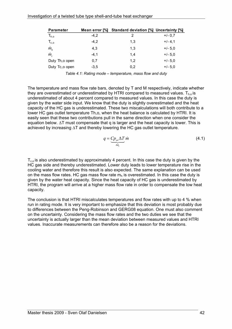
Investigation of a twisted tube type shell-and-tube heat exchanger
Master thesis 2009 - Sven Olaf Danielsen 42
Parameter Mean error [%] Standard deviation [%] Uncertainty [%]Th,o -4,2 2 +/- 0,7Tc,o -4,2 1,3 +/- 4,1
4,3 1,3 +/- 5,0-4,1 1,4 +/- 5,0
Duty Th,o open 0,7 1,2 +/- 5,0Duty Tc,o open -3,5 0,2 +/- 5,0
hmcm
Table 4.1: Rating mode – temperature, mass flow and duty
The temperature and mass flow rate bars, denoted by T and M respectively, indicate whether they are overestimated or underestimated by HTRI compared to measured values. Th,o is underestimated of about 4 percent compared to measured values. In this case the duty is given by the water side input. We know that the duty is slightly overestimated and the heat capacity of the HC gas is underestimated. These two miscalculations will both contribute to a lower HC gas outlet temperature Th,o, when the heat balance is calculated by HTRI. It is easily seen that these two contributions pull in the same direction when one consider the equation below. ΔT must compensate that q is larger and the heat capacity is lower. This is achieved by increasing ΔT and thereby lowering the HC gas outlet temperature.
e
av
h
q Cp T mΔ
= Δ (4.1)
Tc,o is also underestimated by approximately 4 percent. In this case the duty is given by the HC gas side and thereby underestimated. Lower duty leads to lower temperature rise in the cooling water and therefore this result is also expected. The same explanation can be used on the mass flow rates. HC gas mass flow rate mh is overestimated. In this case the duty is given by the water heat capacity. Since the heat capacity of HC gas is underestimated by HTRI, the program will arrive at a higher mass flow rate in order to compensate the low heat capacity. The conclusion is that HTRI miscalculates temperatures and flow rates with up to 4 % when run in rating mode. It is very important to emphasize that this deviation is most probably due to differences between the Peng-Robinson and GERG08 equation. One must also comment on the uncertainty. Considering the mass flow rates and the two duties we see that the uncertainty is actually larger than the mean deviation between measured values and HTRI values. Inaccurate measurements can therefore also be a reason for the deviations.

Investigation of a twisted tube type shell-and-tube heat exchanger
Master thesis 2009 - Sven Olaf Danielsen 43
4.3.2 Heat transfer and shell side pressure loss Figure 4.3 shows how accurate the shell side pressure loss is calculated in rating mode. The presentation of the pressure drop accuracy is based on rating simulations performed with Tc,o unknown. In these simulations the shell side mass flow rate is given. This is case is chosen because the pressure drop depends very much on the HC gas mass flow rate. Compared to the measured pressure loss, HTRI overestimate this parameter with a mean of approximately 40%. In other words HTRI calculate the pressure drop in a very conservative way. The graph below also shows how accurate the overall heat transfer coefficient is predicted in rating mode. The heat transfer coefficient U has an average error of +50%. It means that HTRI overestimates the twisted tube capability of transferring heat by a factor of 1,5 in this particular application and operation point. The heat transfer correlations that HTRI uses for determination of U are in general not conservative, but the other way around.
Rating mode - heat transfer and pressure loss
shell delta P U-10
0
10
20
30
40
50
60
70
80
1
Dev
iatio
n fr
om m
easu
rem
ents
[%]
Figure 4.3: HTRI calculation error in rating mode for pressure loss and heat transfer coefficient
Parameter Mean error [%] Standard deviation [%] Uncertainty [%]Delta P 41,7 3,5 +/- 3,2U 49,5 3,1 +/- 8,6
Table 4.2: Rating mode – shell side pressure loss and heat transfer coefficient
Since mass flow rates have an impact on U, the mean value from HTRI is found by using the rating runs were both mass flow rates were given from measurements. The rating simulations used is therefore when Th,o was kept unknown. In addition, the duty is most accurate in this case. One must also comment on how the measured U value has been predicted. Obviously this parameter can not be measured directly. However, it can be determined from measurements of other physical parameters. Measured U is found by dividing the duty on shell side (HC gas) by heat transfer area and log mean temperature difference. It means that measured U is a result of GERG08 prediction of the heat capacity of HC gas. If the measured U had been calculated by use of Peng-Robinson it had been reduced by 3,5%VI and thereby the calculation accuracy would have looked slightly better.
VI See Table 4.1

Investigation of a twisted tube type shell-and-tube heat exchanger
Master thesis 2009 - Sven Olaf Danielsen 44
4.4 HTRI calculation error in simulation mode
4.4.1 Temperature and mass flow rate In simulation mode HTRI has the capability to calculate with two process parameters unknown. When running in simulation mode the duty of the heat exchanger is not given by the user but calculated by HTRI. Four different combinations of unknowns were tested; both outlet temperatures, both mass flow rates and the two combinations of one temperature and one flow rate. Examining Figure 4.4 below one can observe that there is a huge difference in calculation accuracy depending on which parameters that are unknown. Keeping both outlet temperatures unknown give a relatively low deviation compared to measurements, while keeping both mass flow rates unknown result in a deviation reaching almost 200%. Without investigation of the HTRI programme code it is difficult to point out what makes the error huge in some specific cases. One explanation could be the following.
Simulation mode - temperature and mass flow
Tc,o Th,o
unknownTc,o mh
unknownTh,o mc
unknownmh mc
unknown
-200
20406080
100120140160180200
1
Dev
iatio
n fr
om m
easu
rem
ents
[%]
Figure 4.4: HTRI calculation error in simulation mode for temperature and mass flow rate
Parameter Mean error [%] Standard deviaton [%] Uncertainty [%]Tc,o 1,9 1,4 +/- 4,1Th,o -6,6 0,6 +/- 0,7
Tc,o 100,9 3,7 +/- 4,1
112,4 5,5 +/- 5,0
Th,o -6,7 0,6 +/- 0,7
2 1,4 +/- 5,0
176,6 10,1 +/- 5,0166,4 10,8 +/- 5,0
hm
cm
hmcm
Table 4.3: Rating mode – temperatures and flow rates
It is known from Chapter 2 that the overall heat transfer coefficient has a strong dependency on the flow rates, expressed in Reynolds number. The iteration process in HTRI uses the

Investigation of a twisted tube type shell-and-tube heat exchanger
Master thesis 2009 - Sven Olaf Danielsen 45
local heat transfer coefficient to predict how much heat is transferred between the two fluids. It is also known from the tests in rating mode that HTRI overestimates heat transfer coefficient by a factor of 1,5. When both flow rates are unknown HTRI will start to iterate with low flow rates. Because the heat transfer coefficient is too high, the heat exchanger appears to be more efficient than in reality, and the outlet temperature will be too low for HC gas and too high for seawater respectively. In order to get the specified outlet temperatures HTRI must increase both flow rates. When the flow rate increase, the heat transfer coefficient will also increase in the power of 0,8VII. These two mechanisms will pull the temperatures in opposite directions. Therefore the program must increase the flow rate substantially in order to get the right outlet temperatures. One can illustrate the mechanism by investigating the following equations.
, ,( ) ( ) hlm h h o c iUA T Cp T T mΔ = −i
(4.2)
, , ( )h ch o h i
hh
UAT T T TCp m
= − −i (4.3)
Investigating equation (4.3) one observe that increasing the shell side mass flow rate will at first sight lead to an increased Th,o. But as mentioned the overall heat transfer coefficient increase at almost the same rate and therefore HTRI end up with a way too high mass flow rate. This explanation can also be used in the case were Tc,o and mh are unknown. The cases with both Tc/Th and Th,o/mc unknown are much more accurate. These cases have in common that mh is known. Because mh is known the heat transfer coefficient will approach a constant behaviour. Despite the fact that the heat transfer coefficient is too high, the program will reach a solution earlier at a value closer to the reality. One can conclude that the twisted tube add on in HTRI is unpredictable in simulation mode. Use of simulation mode should be done with caution and both mass flow rates should be input.
VII See section 2.3 p.5

Investigation of a twisted tube type shell-and-tube heat exchanger
Master thesis 2009 - Sven Olaf Danielsen 46
4.4.2 Shell side pressure loss, heat transfer coefficient and duty In the previous section accuracy for temperature and flow rate values were tested. The HTRI calculations appeared to be very unpredictable. In order to show the best side of HTRI the pressure loss, heat transfer and duty values are in this section based on simulation performed with Tc,o/Th,o unknown. The results are presented in Figure 4.5 below.
Simulation mode - pressure loss, heat transfer and duty
shell delta P U Duty-10
0
10
20
30
40
50
60
70
80
1
Dev
iatio
n fr
om m
easu
rem
ents
[%]
Figure 4.5: HTRI calculation error in simulation mode for duty, pressure loss and heat transfer
Parameter Mean error [%] Standard deviation [%] Uncertainty [%]Delta P 38,4 3,4 +/- 3,2U 48,6 2,6 +/- 8,6Duty 2,4 0,6 +/- 5,0
Table 4.4: Rating mode – duty, pressure loss and heat transfer
Here one should expect deviations that are about the same as in rating mode. Comparison of the pressure loss and heat transfer coefficient to the values calculated in rating mode show that the calculations are in agreement. Rating mode and simulation mode overestimate the pressure loss of about 40%. This means that the twisted tube heat exchanger perform better in reality than calculated in HTRI. The overall heat transfer coefficient is overestimated by approximately 50%. In this case the heat exchanger performs worse than predicted by HTRI. When it comes to temperatures and flow rates, rating mode calculates these values by an accuracy of +/-4%. The main reason for the deviation is the use of Peng-Robinson equation of state which is not in agreement with GERG08 equation. In simulation mode the calculation accuracy depends very much on the input. If both mass flow rates were left unknown the error is up to 200% compared to measured values. The reason for this is probably a combination of the overestimation of U and the fact that U is dependent on both flow rates. It is therefore preferable to do simulations were both flow rates are known. The accuracy on temperatures and flow rates are then at +/- 7%.

Investigation of a twisted tube type shell-and-tube heat exchanger
Master thesis 2009 - Sven Olaf Danielsen 47
5 Evaluation of the twisted tube design for 25-HA-113 In this chapter the twisted tube heat exchanger installed on tag number 25-HA-113, LNG Hammerfest is investigated with respect to thermal-hydraulic performance. The design is developed by the company Koch Heat Transfer Incorporated. Calculations done in the design process were based on the design basis E066-AB-P-DP-2546. In this document information about the operational gas physical properties, inlet temperatures and mass flow rates are given. The performance of the heat exchanger is therefore designed to be in agreement with these input values. 25-HA-113 is run at a different operation point than specified in the design basis. In order to compare the performance expected by Koch with measured performance data, one must take into account that there is a deviation between given operation point in the design basis and the real operation point.
5.1 Overdesign and fouling resistance included in design Overdesign is the extra margin incorporated in a design. It is important to do so in order to cover uncertainties in flow rates, temperatures, physical properties and the software used in the design process. In this case the overdesign is set to 5%. The overdesign is included in the HTRI model by adding 5 percent to the HC gas mass flow rate. The increased mass flow rate results in a heat exchanger design that is able to handle a 5% higher duty than the design operation point. In addition to the input uncertainties one has taken fouling into account. Fouling will increase the thermal resistance at the wall and thereby lower the overall heat transfer coefficient over time. StatoilHydro has requested a fouling resistance of 1,8 E-4 m2K/W to be included in the design. 5.2 Heat transfer performance The thermal performance of the twisted tube design will be investigated in this section. A convenient parameter to examine for this matter is the overall heat transfer coefficient, U. In the following different variations of U will be explained and derived. At the section end, these parameters are plotted in a diagram showing the thermal performance of the heat exchanger. The first explained parameter is the measured heat transfer coefficient Umeasured.
5.2.1 Measured heat transfer coefficient Measured heat transfer coefficient are predicted by using the duty of the heat exchanger. The duty is calculated by a GERG08 equation of state which returns the enthalpy for a known pressure and temperature. The enthalpy difference of the refrigerant from inlet to outlet is then multiplied by the measured mass flow rate. fg is assumed equal to 1 and the shell side area, As is extracted from TEMA specification sheet in Appendix I.
_ _, ,( )hh e h i e h oQ m h h= −i
(4.4) /( )h g lm sU Q f T A= ⋅Δ ⋅ (4.5)
Investigation of a twisted tube type shell-and-tube heat exchanger
Master thesis 2009 - Sven Olaf Danielsen 48
5.2.2 Design heat transfer coefficient The design U is here defined as the overall heat transfer coefficient required to cool the gas as specified in the design basis, operating at design point in fouled condition. The heat transfer area must be specified to determine this parameter. Here the calculated efficient area from HTRI is used.
,
designd
lm design HTRI
QU
T A=Δ
(4.6)
5.2.3 Clean heat transfer coefficient Clean U is found by subtracting the expected fouling resistance Rf from the design U. This parameter represents the expected heat transfer coefficient when the exchanger is new and clean
1
1clean f
design
U RU
−⎛ ⎞
= −⎜ ⎟⎜ ⎟⎝ ⎠
(4.7)
5.2.4 Corrected heat transfer coefficient for off design operation It is interesting to compare design U with U measured. However, the heat exchanger was operating away from design point when the measurements were performed. It is therefore not fair to compare these two values directly. Operation away from design point will affect U measured which makes a comparison less valuable. A technique is developed to make U measured and design U comparable. This is done by normalizing U measured with the heat correlations presented in section 2.3.2. By mathematical manipulation it is possible to obtain a corrected heat transfer coefficient. U corrected is the thermal performance one would expect if the heat exchanger was run at design conditions. In order to predict U corrected the following mathematical method has been used. The heat transfer coefficient must always be evaluated for a certain area. For simplicity U corrected is developed for a circular tube area, not for the twisted tube. A circular tube that has the same cross sectional flow area as the twisted tube is chosen in the mathematical analysis. By using this assumption one can calculated a circular equivalent diameter dce. This is the diameter that corresponds to a circular tube with the same cross sectional area as the twisted tube. The circular equivalent dce can be calculated by use of equation (2.3) for twisted tube cross sectional area, assumption of dt,max/dt,min (tube side diameters) = 2 and the area formula for a circular cross section. Combination of these three equations result in the following expression for the circular equivalent tube side diameter dt,ce for the circular tube.
,max, 2
tt ce
dd = (4.8)
By using the wall thickness Lt = 1,734mm and ds,max = 22,225 mm (see Appendix I for design specification), one can calculate the corresponding circle diameters dt,ce and ds,ce. The following correlation for U is expressed based on the shell side area considering a clean unit without fouling layer [11].
Investigation of a twisted tube type shell-and-tube heat exchanger
Master thesis 2009 - Sven Olaf Danielsen 49
,, , , ,
, , ,
1ln( / )1
2
t correcteds ce t ce s ce s ce
s corrected c t ce t corrected
U d d d dh k d h
=+ +
(4.9)
By simplification of equation (2.20) and considering that the application is cooling on the shell side where the temperature ratio exponent n=0, hs,corrected can be written 0,8 0,4
, Re Prs corrected design designh K= (4.10) Here K is unknown. In order to get an expression for hs,corrected that can be calculated, the above equation is expanded in the following way
0,8 0,4
0,8 0,4, 0,8 0,4
_,
Re PrRe Pr
Re Prdesign design
s corrected
hs measuredcorrection terms
h K⎛ ⎞ ⎛ ⎞
= ⎜ ⎟ ⎜ ⎟⎝ ⎠ ⎝ ⎠
(4.11)
Observed from HTRI calculations it turns out that the thermal resistance distribution is 75% for shell side convection, 15% for tube side convection and 10% for tube conduction for a clean unit. All terms in equation (4.11) can be determined by use of measured data, design specifications and the information on thermal resistance. To find hs,measured the following relation is used.
, 0,75measured
s measuredUh = (4.12)
The correction terms are calculated by using the below formulas for Reynolds number and Prandtl number
0,80,8
0,8
0,8
, ,
c
_
_ _ _ _os
ReRe
[1 0,00186( )]
design flow
design flowdesign
design designh i h i design
change in vis ity from designdesign
A mAm
m m T Tm m
μμ
μ
μ
⎧ ⎫⎛ ⎞⎛ ⎞⎛ ⎞⎛ ⎞ ⎪ ⎪⎜ ⎟= =⎜ ⎟⎜ ⎟⎨ ⎬⎜ ⎟ ⎜ ⎟⎜ ⎟⎜ ⎟⎝ ⎠ ⎪ ⎪⎝ ⎠⎝ ⎠⎝ ⎠⎩ ⎭
⎛ ⎞⎜ ⎟ = + −⎜ ⎟⎜ ⎟⎝ ⎠
i
i
i i
i i
0,8⎛ ⎞⎜ ⎟⎜ ⎟⎝ ⎠
(4.13)
The change in viscosity term is found by use of the Peng-Robinson equation of state in HTRI. Small pressure differences have negligible influence on the viscosity while variations in temperature are correlated linearly as showed in the above equation. See Appendix H for details. In the following formula for Prandtl number, Peng-Robinson has been used additionally to correlate the heat capacity with pressure and temperature. The conduction terms will cancel each other.

Investigation of a twisted tube type shell-and-tube heat exchanger
Master thesis 2009 - Sven Olaf Danielsen 50
_
0,40,4,
0,4,
0,4
, , _, ,
PrPr
1[1 0,00186( )] [1 0,0035( )]
design p design design c
c design p
h i h i design h i h i design
c kk c
T T p p
μμ
⎛ ⎞⎛ ⎞= =⎜ ⎟⎜ ⎟ ⎜ ⎟⎝ ⎠ ⎝ ⎠
⎛ ⎞⎜ ⎟⎜ ⎟+ − + + −⎝ ⎠
(4.14)
Now hs,corrected can be determined knowing all the terms in (4.11). A similar approach as the one presented above is used to find the corrected tube side convection coefficient ht,corrected by using equation (2.24). Since the application is heating of liquid the temperature ratio is replaced by the viscosity ratio with an exponent m=-0,11.
0,8 0,4 0,11, Re Pr ( )w
t correctedb
h K μμ
−= ⋅ (4.15)
The procedure from here is exactly the same expanding (4.15) with correction terms.
0,11 0,11 0,110,8 0,4
0,8 0,4, 0,8 0 4
_
,
,
Re PrRe Pr
Re Prdesign designw w b
t correctedb b wdesign
h correction termst measured
h K μ μ μμ μ μ
− − −⎛ ⎞ ⎛ ⎞ ⎛ ⎞⎛ ⎞ ⎛ ⎞
= ⎜ ⎟ ⎜ ⎟ ⎜ ⎟⎜ ⎟ ⎜ ⎟⎝ ⎠ ⎝ ⎠⎝ ⎠ ⎝ ⎠ ⎝ ⎠
(4.16)
The viscosity and Prandtl number ratios is assumed one since these properties have negligible variations for the actual pressure and temperature deviations. Correction terms for Reynolds number is presented below. In prediction of ht,measured one must also correct for the area that U is based on by using dce.
,,
, 0,15s ce measured
t measuredt ce
d Uh
d= (4.17)
0,80,8
, ,0,8
cos
_
_ _ _ _
Re(1 0,0478( ))
Redesigndesign
c i design c i
change in vis ity from design
m T Tm
⎛ ⎞⎛ ⎞ ⎜ ⎟= + −⎜ ⎟ ⎜ ⎟⎝ ⎠ ⎝ ⎠
i
i (4.18)
Now we have all the terms required to calculated ht,corrected. By use of the information on thermal resistance distribution it is also possible to calculate the conduction term in (4.9). This term will not change with operation and can therefore be calculated from Umeasured.
, , ,ln( / ) 0,10s ce s ce t ce
c measured
d d dk U
= (4.19)
All terms in equation (4.16) are now determined and the corrected heat transfer coefficient Ucorrected can be calculated. In the next section the results from this analysis are presented.

Investigation of a twisted tube type shell-and-tube heat exchanger
Master thesis 2009 - Sven Olaf Danielsen 51
5.2.5 Presentation of 25-HA-113 thermal performance
Thermal performance
400
500
600
700
800
900
1000
november 2008 desember 2008 januar 2009
Time [months]
Ove
rall
heat
tran
sfer
coe
ffici
ent U
[W/m
2 K]
Clean U
Design U
Measured U
Corrected U
Flow HC
Figure 5.1: Thermal performance of 25-HA-113
Parameter Mean Standard deviation Uncertainty UnitClean U 929,6 - - W/m2KDesign U 796,4 - - W/m2KMeasured 744,0 23,3 +/- 64 W/m2KCorrected U 725,7 7,2 +/- 64 W/m2K
Table 5.1: Thermal performance in numbers
Figure 5.1 presents the thermal performance of the twisted tube heat exchanger. The diagram is based on 25 measurements performed on 25-HA-113 from 26.october 2008 to 2.february 2009. In other words the heat exchanger is expected to be in new and clean condition. It is observed that the measured U is lower than both design U and clean U in the actual time period. One explanation could be that the heat exchanger is run at off design conditions. If these conditions are unfavourable for the heat transfer coefficient the measured value will be lower than the actual value at design point. However, when one corrects the measured U for the operation point (indicated by Corrected U) it is seen that the true thermal performance is even lower than measured. The heat exchanger is operated with higher flow rates than specified in the design. Higher flow rates contribute to better thermal performance. This is emphasized by also showing flow rate of HC gas in the same diagram indicated by a brown curve. One can clearly observe that the measured U follows the same pattern as the shell side mass flow rate. Because the heat exchanger is run at a favourable operation point in terms of heat transfer coefficient, the corrected U will be lower than the measured U. Corrected U has an average value of 726 W/m2K while measured U has an average value of 744 W/m2K.

Investigation of a twisted tube type shell-and-tube heat exchanger
Master thesis 2009 - Sven Olaf Danielsen 52
The expected heat transfer coefficient by the vendor, design U, has an average of 796 W/m2K. This is considerably higher than the mean measured value, 744 W/m2K. If one compare with the corrected U, which reflects the true performance at design operation point, the gap between design and measured values are even larger. This underlines the fact that the heat exchanger is not able to transfer the amount of heat that was specified in the design. In other words the vendor has overestimated its thermal performance. It was shown in Chapter 4 that the software HTRI Xchanger Suite predicts the heat transfer 50% higher than the real value in the case of 25-HA-113. When Koch Heat Transfer Incorporated uses this software as a design tool it may result in an insufficient thermal designs.

Investigation of a twisted tube type shell-and-tube heat exchanger
Master thesis 2009 - Sven Olaf Danielsen 53
5.3 Shell side pressure drop The hydraulic performance of the twisted tube design will be investigated in this section. In the intercooling application of 25-HA-113 the pressure drop of HC gas on shell side is the concern. Therefore only the shell side pressure drop is investigated here. A convenient parameter to examine for this matter is obviously the pressure drop Δp from shell inlet to shell outlet. In the following Δp corrected will be explained and derived. At the section end, the parameter is plotted with measured Δp in a diagram showing the hydraulic performance of the heat exchanger.
5.3.1 Corrected pressure loss for off design operation In the same manner as for the overall heat transfer coefficient it is interesting to determine a corrected Δp in order to compare the result with the design pressure drop. By using correlations from section 2.3.3 one can correct the measured values. The method is initiated by inserting equation (2.29) for fD in equation (2.28).
20,25 0,357
0,3164 3,6[1 ]Re 2 h
LP vFr d
ρΔ = + (4.20)
By including constant parameters into K one can simplify to 0,25 2ReP K vρ−Δ = (4.21) Expanding the above equation with correction terms for off design operation one obtain the corrected pressure loss, Δpcorrected
0,25 20,25 2
20,25
,0,25 2
__
ReRe
Re
ReRe
Re
design design designcorrected
h designdesign
designh
measured pressurelosscorrection terms
vp K v
v
mK vm
ρρ
ρ
ρρρ
−
−
−
−
⎛ ⎞ ⎛ ⎞⎛ ⎞Δ = =⎜ ⎟ ⎜ ⎟⎜ ⎟
⎝ ⎠⎝ ⎠⎝ ⎠
⎛ ⎞ ⎛ ⎞⎛ ⎞ ⎜ ⎟ ⎜ ⎟⎜ ⎟ ⎜ ⎟⎜ ⎟⎝ ⎠ ⎝ ⎠⎝ ⎠
i
i
(4.22)
The first correction term can be calculated directly from measurements and design specifications. A correlation for the last term is developed by using Peng-Robinson property generator in HTRI.
, _,[1 0,0566( )h i h i designdesign
p pρρ
= + − (4.23)
Using the above correlations it is possible to calculate a corrected pressure drop, Δpcorrected. This parameter reflects the pressure drop one would expect if 25-HA-113 were run at design operation point. In addition, it is interesting to investigate the measured pressure loss Δpmeasured in comparison to the design value ΔPdesign. Measured pressure loss is extracted directly from the measurement data while design pressure loss is the pressure loss predicted by Koch when they developed the design. The results on hydraulic performance are presented in the following.
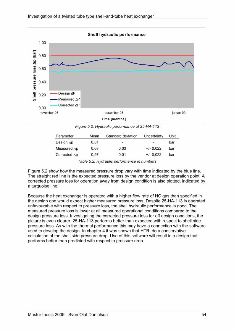
Investigation of a twisted tube type shell-and-tube heat exchanger
Master thesis 2009 - Sven Olaf Danielsen 54
Shell hydraulic performance
0,00
0,20
0,40
0,60
0,80
1,00
november 08 desember 08 januar 09
Time [months]
Shel
l pre
ssur
e lo
ss Δ
p [b
ar]
Design ΔP
Measured ΔP
Corrected ΔP
Figure 5.2: Hydraulic performance of 25-HA-113
Parameter Mean Standard deviation Uncertainty UnitDesign Δp 0,81 - - barMeasured Δp 0,68 0,03 +/- 0,022 barCorrected Δp 0,57 0,01 +/- 0,022 bar
Table 5.2: Hydraulic performance in numbers
Figure 5.2 show how the measured pressure drop vary with time indicated by the blue line. The straight red line is the expected pressure loss by the vendor at design operation point. A corrected pressure loss for operation away from design condition is also plotted, indicated by a turquoise line. Because the heat exchanger is operated with a higher flow rate of HC gas than specified in the design one would expect higher measured pressure loss. Despite 25-HA-113 is operated unfavourable with respect to pressure loss, the shell hydraulic performance is good. The measured pressure loss is lower at all measured operational conditions compared to the design pressure loss. Investigating the corrected pressure loss for off design conditions, the picture is even clearer. 25-HA-113 performs better than expected with respect to shell side pressure loss. As with the thermal performance this may have a connection with the software used to develop the design. In chapter 4 it was shown that HTRI do a conservative calculation of the shell side pressure drop. Use of this software will result in a design that performs better than predicted with respect to pressure drop.

Investigation of a twisted tube type shell-and-tube heat exchanger
Master thesis 2009 - Sven Olaf Danielsen 55
5.4 Consideration of fouling on 25-HA-113
Fouling
600
620
640
660
680
700
720
740
760
780
800
26. nov. 6. des. 16. des. 26. des. 5. jan. 15. jan. 25. jan.
Time [days]
Ove
rall
heat
tran
sfer
coe
ffici
ent U
[W/m
2 K]
Measured U
Corrected U
Linear (Measured U)
Linear (Corrected U)
Figure 5.3: Developement of fouling layer on 25-HA-113
The diagram above shows the development of the heat transfer coefficient with time. Both measured U and corrected U are plotted. In addition each curve has a linear regression line that visualizes the trend with respect to time. As the heat exchanger was recently installed 26.november 2008 one can consider the unit in clean condition. One would expect the overall heat transfer coefficient to decrease with time as a result of a growing fouling layer. Both linear trend lines show the opposite effect by a minimal increase of heat transfer coefficient with time. The increasing measured U could be explained by a change to more favourable operation conditions with respect to heat transfer, but the linear regression of the corrected U also shows an increasing trend. This line is not affected by changing operation conditions. The increasing trends are therefore most probably due to uncertainty in measurement and the correlations used for calculating the corrected U. Investigation of Figure 5.3 shows that the corrected U has a clear decreasing trend from 26.november to approximately 1.december. The corrected U is then increasing until 6.december. When the heat exchanger was installed there may have been a process where a fouling layer first developed and then has fallen off as result of shear forces exerted by the seawater flow. By observing the development of the measured and corrected heat transfer coefficient one can conclude that the thermal performance is unaffected in the time period considered. Therefore the development of a fouling layer is most probably minimal on 25-HA-113.

Investigation of a twisted tube type shell-and-tube heat exchanger
Master thesis 2009 - Sven Olaf Danielsen 56
6 Comparison of the twisted tube solution to other heat exchanger concepts
As a part of the comparison between twisted tube heat exchangers and competing heat exchanger solutions the simulation program HTRI has been used. By using this software and specifying a certain application it is possible to compare the heat exchanger types not only qualitatively but also quantitatively. The application investigated in this analysis is the seawater cooled intercooler 25-HA-113 described in section 3.1 p.24. The design basis for this application can be found in StatoilHydro’s PIM system at document number E066-AB-P-DP-2546 [16]. Chosen heat exchanger concepts evaluated for this application are a twisted tube, a helix baffled and a single segmental baffled heat exchanger. The twisted tube is the present installed unit on 25-HA-113VIII, while the helix heat exchanger is the previously installed unit at the same tag number. Measurement data form both units are available. The conventional shell and tube solution has been designed in HTRI for the application 25-HA-113 corresponding to the design basis. This heat exchanger is only a HTRI design performed for this investigation and has never been in operation. In addition HTRI files for both the twisted tube and the helix configuration is used in some parts of the analysis. The helix baffled heat exchanger has been reconstructed in HTRI by using technical drawings (can be found in Appendix F), while the twisted tube design was reconstructed by using the “as built” HTRI file provided by Koch Heat Transfer Inc. By using HTRI the conventional design is compared to the former installed helix baffled and the present twisted tube heat exchanger. It must be emphasized that the comparison of thermal hydraulic performance is based on field measurements from the twisted tube and helical baffled heat exchangers, while the conventional thermal-hydraulic performance is extracted from HTRI calculations. This is done in order to increase the reliability of the analysis. Other parameters such as size and weight will also be presented. In addition, their properties in terms of fouling and vibration will be discussed qualitatively. 6.1 Descriptions of the designs for 25-HA-113
6.1.1 Low finned tubes with single segmental baffles It was decided to develop a standard shell and tube heat exchanger design with single segmental baffles. The application is cooling of gas by seawater. Gases exhibit low heat transfer coefficients due to their low thermal conductivity and low density, while liquids in general exhibit high heat transfer coefficients [12]. To compensate for this property it is advantageous to increase the gas side heat transfer area. In order to be competitive compared to the other more sophisticated designs, the tubes are therefore chosen to be low finned on the shell side. Normally low finned tubes give a relatively high heat transfer to pressure drop ratio. In addition, designing the heat exchanger with low finned tubes result in a compact unit due to the high heat transfer surface achieved. This is the simplest design among the three alternatives. In the design process some parameters have been fixed such that the solution is a true alternative to the two other designs. The parameters that are fixed include the following.
VIII June 2009
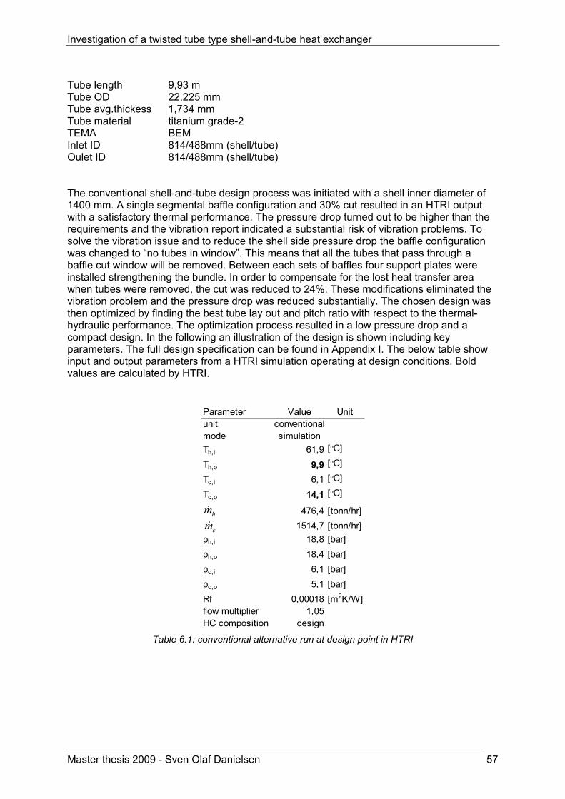
Investigation of a twisted tube type shell-and-tube heat exchanger
Master thesis 2009 - Sven Olaf Danielsen 57
Tube length 9,93 m Tube OD 22,225 mm Tube avg.thickess 1,734 mm Tube material titanium grade-2 TEMA BEM Inlet ID 814/488mm (shell/tube) Oulet ID 814/488mm (shell/tube) The conventional shell-and-tube design process was initiated with a shell inner diameter of 1400 mm. A single segmental baffle configuration and 30% cut resulted in an HTRI output with a satisfactory thermal performance. The pressure drop turned out to be higher than the requirements and the vibration report indicated a substantial risk of vibration problems. To solve the vibration issue and to reduce the shell side pressure drop the baffle configuration was changed to “no tubes in window”. This means that all the tubes that pass through a baffle cut window will be removed. Between each sets of baffles four support plates were installed strengthening the bundle. In order to compensate for the lost heat transfer area when tubes were removed, the cut was reduced to 24%. These modifications eliminated the vibration problem and the pressure drop was reduced substantially. The chosen design was then optimized by finding the best tube lay out and pitch ratio with respect to the thermal-hydraulic performance. The optimization process resulted in a low pressure drop and a compact design. In the following an illustration of the design is shown including key parameters. The full design specification can be found in Appendix I. The below table show input and output parameters from a HTRI simulation operating at design conditions. Bold values are calculated by HTRI.
Parameter Value Unitunit conventionalmode simulationTh,i 61,9 [ºC]
Th,o 9,9 [ºC]
Tc,i 6,1 [ºC]
Tc,o 14,1 [ºC]
476,4 [tonn/hr]1514,7 [tonn/hr]
ph,i 18,8 [bar]ph,o 18,4 [bar]pc,i 6,1 [bar]pc,o 5,1 [bar]Rf 0,00018 [m2K/W]flow multiplier 1,05HC composition design
cmhm
Table 6.1: conventional alternative run at design point in HTRI

Investigation of a twisted tube type shell-and-tube heat exchanger
Master thesis 2009 - Sven Olaf Danielsen 58
Baffle type: single segmental, no tubes in window Support baffles: 4 per baffle set Tube type: low finned Bundle material: titanium

Investigation of a twisted tube type shell-and-tube heat exchanger
Master thesis 2009 - Sven Olaf Danielsen 59
6.1.2 Low finned tubes with helical baffles When Hammerfest LNG plant was built a helical baffled heat exchanger was chosen for 25-HA-113. The design was developed by Lummus Technology Heat Transfer B.V. Autumn 2008 the equipment had a break down and was replaced by a twisted tube heat exchanger. The design of the former helix exchanger is reproduced in HTRI by using data from technical drawings found in StatoilHydros electronic document storage system PIM. The drawings can be found in Appendix F. Geometrical data presented in this chapter such as size and weight is extracted from the HTRI model, while thermal-hydraulic characteristics are based on field measurements. Key parameters and an illustration of the heat exchanger are given below. See Appendix G for complete design description. Baffle type: Double helix Helix angle: 30 degrees Tube type: low finned Bundle material: Titanium

Investigation of a twisted tube type shell-and-tube heat exchanger
Master thesis 2009 - Sven Olaf Danielsen 60
6.1.3 Twisted tube The twisted tube design developed by Koch Heat Transfer Inc. for 25-HA-113 is described in section 3.2 p25.
6.1.4 Used technique to perform an accurate comparison A goal of the presented analysis is to compare the thermal-hydraulic performance of the conventional, helix and twisted tube heat exchanger. The determined thermal-hydraulic performance for twisted tube and helix heat exchanger is based on measurements while for the conventional shell and tube alternative HTRI output is used. By using measurement data for helix and twisted tube the uncertainty in the analysis is reduced considerably. When one investigates the heat exchanger designs it is important that their performance can be compared on the same premises. The twisted tube and the helix units were run at various operation conditions when the used measurements were preformed. In order to get a comparable output from HTRI, the conventional shell and tube heat exchanger is run at an average of these different operation conditions. At this averaged operation point HTRI will calculate one specific value for overall heat transfer and pressure drop while there are many measured values for helix and twisted tube. In order to get one comparable number from the measurements, they are averaged. By using this method the three alternatives are operated virtually at the same conditions. The size, weight and the thermal resistance distribution of the heat exchangers are also compared. In this case values from all heat exchangers are calculated by HTRI. All three HTRI files have been run at an averaged operation point specified in Table 6.2 while Table 6.3 gives an overview of the origin to the different calculated parameters.
Parameter Value Unitunit conventionalmode simulationTh,i 65,6 [ºC]
Th,o 10,5 [ºC]
Tc,i calculatedTc,o calculated
535,9 [tonn/hr]1620,8 [tonn/hr]
ph,i 17,1 [bar]ph,o 15,9 [bar]pc,i 6,1 [bar]pc,o 5,1 [bar]CH4 57,5 %C2H6 28,0 %C3H8 0,2 %N2 14,2 %Rf 0,00018 m2K/Wflow multiplier 1,0
cmhm
Table 6.2: HTRI simulation on averaged operation point for the conventional HE

Investigation of a twisted tube type shell-and-tube heat exchanger
Master thesis 2009 - Sven Olaf Danielsen 61
Parameter Conventional Helix Twisted tubeSize and weight HTRI HTRI HTRIUA HTRI measurement measurementU HTRI combination combinationUA/body volume HTRI combination combinationResistance distribution HTRI HTRI HTRIShell ΔP HTRI measurement measurementUA/shell ΔP HTRI combination combination
Table 6.3: The origin of performance parameters

Investigation of a twisted tube type shell-and-tube heat exchanger
Master thesis 2009 - Sven Olaf Danielsen 62
6.2 Results
6.2.1 Size and weight The diagram below are based on values from HTRI calculations
Size and weigth
Conventional Helix Tw isted tube Conventional Helix Tw isted tube10
12
14
16
18
20
22
24
26
28
30
1
Weight [tonnes] Body size [m^3]
Figure 6.1: Size and weight to the three heat exchanger designs Size and weight are important aspects of heat exchanger design. Both these parameters translate into costs and should therefore be minimized. Especially for off shore applications the volume displaced by the unit will have a substantial influence on the associated investment cost. The weight reflects the material use in the heat exchanger. In this case it is directly comparable because all three bundles are made in Titanium. Increased weight will also require additional foundation which also generates costs. The diagram above show the three alternatives compared to each other. Their size is identical, while the weight differs. One may conclude that the use of material is more efficient in both the helix and the conventional alternative compared to twisted tube.
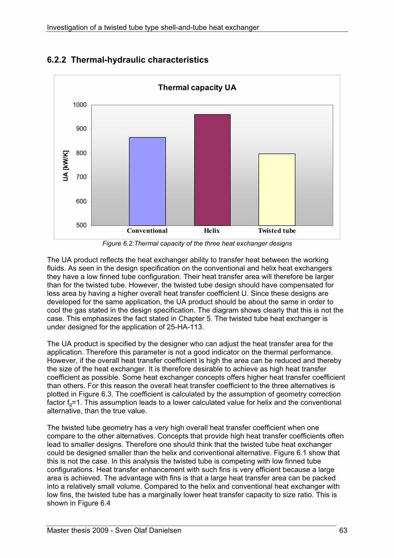
Investigation of a twisted tube type shell-and-tube heat exchanger
Master thesis 2009 - Sven Olaf Danielsen 63
6.2.2 Thermal-hydraulic characteristics
Thermal capacity UA
Conventional Helix Twisted tube500
600
700
800
900
1000
1
UA
[kW
/K]
Figure 6.2:Thermal capacity of the three heat exchanger designs
The UA product reflects the heat exchanger ability to transfer heat between the working fluids. As seen in the design specification on the conventional and helix heat exchangers they have a low finned tube configuration. Their heat transfer area will therefore be larger than for the twisted tube. However, the twisted tube design should have compensated for less area by having a higher overall heat transfer coefficient U. Since these designs are developed for the same application, the UA product should be about the same in order to cool the gas stated in the design specification. The diagram shows clearly that this is not the case. This emphasizes the fact stated in Chapter 5. The twisted tube heat exchanger is under designed for the application of 25-HA-113. The UA product is specified by the designer who can adjust the heat transfer area for the application. Therefore this parameter is not a good indicator on the thermal performance. However, if the overall heat transfer coefficient is high the area can be reduced and thereby the size of the heat exchanger. It is therefore desirable to achieve as high heat transfer coefficient as possible. Some heat exchanger concepts offers higher heat transfer coefficient than others. For this reason the overall heat transfer coefficient to the three alternatives is plotted in Figure 6.3. The coefficient is calculated by the assumption of geometry correction factor fg=1. This assumption leads to a lower calculated value for helix and the conventional alternative, than the true value. The twisted tube geometry has a very high overall heat transfer coefficient when one compare to the other alternatives. Concepts that provide high heat transfer coefficients often lead to smaller designs. Therefore one should think that the twisted tube heat exchanger could be designed smaller than the helix and conventional alternative. Figure 6.1 show that this is not the case. In this analysis the twisted tube is competing with low finned tube configurations. Heat transfer enhancement with such fins is very efficient because a large area is achieved. The advantage with fins is that a large heat transfer area can be packed into a relatively small volume. Compared to the helix and conventional heat exchanger with low fins, the twisted tube has a marginally lower heat transfer capacity to size ratio. This is shown in Figure 6.4

Investigation of a twisted tube type shell-and-tube heat exchanger
Master thesis 2009 - Sven Olaf Danielsen 64
Overall heat transfer coefficient, U
Conventional Helix Twisted tube0
100
200
300
400
500
600
700
800
1
UA [W
/m2 K]
Figure 6.3: The thermal performance of the three alternatives
UA/Body volume
Conventional Helix Twisted tube0
20
40
60
80
100
1
UA/V
[W/m
5 K]
Figure 6.4: Heat transfer capacity to volume ratio

Investigation of a twisted tube type shell-and-tube heat exchanger
Master thesis 2009 - Sven Olaf Danielsen 65
6.2.3 Thermal resistance distribution
Conventional
metal 6 %
tube 23 %
fouling 22 %
shell 49 %
Helix
shell 61 %
metal 5 %
tube 15 %
fouling 19 %
Twisted tube
shell 59 %
metal 8 %
tube 13 %
fouling 20 %
Figure 6.5: The distribution of thermal resistance for the three concepts
Investigation of a twisted tube type shell-and-tube heat exchanger
Master thesis 2009 - Sven Olaf Danielsen 66
Figure 6.5 shows the distribution of the thermal resistance on tube side, shell side and through the metal for the three heat exchanger concepts. The numbers are based on HTRI simulations at the averaged operation point. In the application of 25-HA-113 the shell side fluid is a hydrocarbon based gas. Gases exhibit extremely low heat transfer coefficients due to their low thermal conductivity and low density. The tube side fluid is seawater which provides higher heat transfer coefficients. Therefore it is favourable to enhance the heat transfer capacity on the shell side. This is done by using low finned tubes in the conventional and helix concept. The twisted tube has no expanded area on the shell side that will increase the heat transfer capacity. One should therefore expect that the thermal resistance on the shell side is high for twisted tube compared to the two other alternatives. The sector diagram show that this is the case to some extent, but it is not a clear pattern. The twisted tube has a shell side heat transfer area of 1071m2, while helix and the conventional heat exchanger have 2109m2 and 1619m2 respectively. It appears that the twisted tube to some extent compensate the small area by having a higher convective heat transfer coefficient on shell side relative to the other concepts. Consideration of the tube side thermal resistance for the twisted tube show that it is very low compared to the shell side. This has obviously to do with the fact that seawater exhibits a high convective heat transfer coefficient. When one compare with the other alternatives the thermal resistance show the same tendency on the tube side. But the tube side resistance is of higher importance for helix and the conventional concepts. In these two configurations the tube side flow is inside a plain tube, in contrast to the twisted tube. As explained in section 2.3.1 the twisted shape will enhance the tube side heat transfer compared to a plain tube. This may be the reason why the thermal resistance distribution looks the way Figure 6.5 illustrates.

Investigation of a twisted tube type shell-and-tube heat exchanger
Master thesis 2009 - Sven Olaf Danielsen 67
6.2.4 Shell side pressure drop
Shell side pressure drop
Conventional Helix Twisted tube0
0,4
0,8
1,2
1,6
2
1
Δp [b
ar]
Figure 6.6: Shell side pressure drop predicted for the three concepts
The diagram above shows the shell side pressure drop for the three competing concepts. The helical baffled configuration contributes to a pressure drop on the hydrocarbon gas by almost 200 kPa. Considering that 70 kPa is specified in the design basis, this is a very high value. The twisted tube and the conventional heat exchanger perform much better with respect to pressure drop. Both designs are within the limits specified in the design basis. When designing a heat exchanger a trade off between heat transfer and pressure loss must be considered. The ratio of these two parameters gives a good indication on the thermal-hydraulic performance of the different concepts. This ratio is presented in Figure 6.7
Heat transfer capacity to shell side pressure drop ratio
Conventional Helix Twisted tube0
200
400
600
800
1000
1200
1400
1
UA/Δ
p [k
W/b
arK
]
Figure 6.7: Heat transfer capacity to pressure drop ratio for the three concepts

Investigation of a twisted tube type shell-and-tube heat exchanger
Master thesis 2009 - Sven Olaf Danielsen 68
The conventional heat exchanger achieves the highest heat transfer capacity to pressure drop ratio followed by the twisted tube. As a result of the substantial shell side pressure loss in the helix concept this unit has a low thermal-hydraulic performance. All the results presented in this chapter are summed up in the table below.
Conventional Helix Twisted tubeID 1400 1400 1390 mmTube Length 9,93 9,994 9,926 mTube OD 22,225 19,05 22,225 mmTube thickness 1,734 1,25 1,734 mmNumber of tubes 1435 1078 1591Pitch 26,78 32 27,781Lay out 30 45 60 degreesEffective area 2109,03 1618,85 1070,87 m2
Weigth dry 25,648 23,797 26,878 kgU fouled 410 593 744 W/m2KShell Δp 0,60692 1,84 0,68 barBody volume 15,29 15,38 15,06 m3
Area/volume 137,97 105,23 71,10 1/mUA 865,38 959,98 796,73 W/KUA/volume 56,61 62,40 52,90 W/m3KUA/Δp shellside 1425,85 521,73 1171,66 kW/barKU/Δp shellside 676,07 322,28 1094,12 W/m2barK
Table 6.4: Summery of the numbers given in chapter 6
6.2.5 Fouling Dead spot is a location in the heat exchanger where the flow has low velocity relative to the bulk velocity. This may result in extreme temperatures in the actual regions. At such locations the risk for development of a fouling layer is increased. The twisted tube geometry provoke circulation and mixing on both tube and shell side. This not only improves the heat transfer coefficient but also avoid the risk for dead spots in the heat exchanger. How the 25-HA-113 twisted tube unit performs with respect to fouling is presented in section 5.4. The helical baffled exchanger has the same properties on this issue. Such baffle configuration ensures a smooth flow path lowering the risk for dead spots. In the segmental baffled heat exchanger the flow is turned vertically by the baffles. Such flow pattern will have an uneven velocity distribution in the turns. At these locations the flow has low velocity close to the shell wall. This makes the segmental baffled design most exposed to fouling.

Investigation of a twisted tube type shell-and-tube heat exchanger
Master thesis 2009 - Sven Olaf Danielsen 69
6.2.6 Vibration Vibration has been the cause of many heat exchanger break downs. These vibrations arise when fluid is passing the tubes on the shell side. There are two ways to overcome the vibration problem. One can strengthen the bundle construction by installing more baffles. The other solution is to change the flow direction to a more favourable one such that the flow induced vibration is reduced. The twisted tube uses both solutions. This is done by directing the flow along the tubes and by supporting each tube six times to the adjacent tubes per 360 degree twist. Such design gives a very rigid construction that is so to speak vibration free. Why the twisted tube is not exposed to flow induced vibration is discussed in more detail in section 2.5. In contrast the segmental baffled heat exchanger has two unfavourable design properties that make it vulnerable to vibrations. The flow is passing perpendicular to the tubes inducing severe vibration. In addition there is a large distance (relative to the twisted tube) between each location where the tube is supported by the baffle. The tubes will therefore have a relatively low eigen frequency making them more exposed to flow induced vibration. The helical baffled heat exchanger is also vunerable to vibration in the same way as the segmental baffled configuration. This can be solved to some extent by installing two helix baffles and thereby give additional support to the tubes. However it must be emphasized that the helical baffled design presented in this analysis had a broke down due to vibrations. This underlines the fact that the double helix can be exposed to a vibration problem if the design is unfavourable.
6.2.7 Qualitative summery of the differences in performance The twisted tube design is an alternative to more traditional designs like a conventional shell and tube exchanger with single segmental baffles or helical baffles. In the present analysis the twisted tube is compared to these two designs equipped with low finned tubes. Only one application where gas is cooled by seawater is considered here. A comparison may be different for other applications. The thermal performance of the twisted tube is very good compared to the two alternatives. On the other hand the heat transfer area on the shell side is small on shell side were the heat transfer coefficient is limited. The twisted tube is not able to fully compensate the small area with higher overall heat transfer coefficient. This problem could be solved by designing the heat exchanger with more tubes providing a larger area. But then the concept is no longer competitive in terms of size and weight. The hydraulic performance of the twisted tube is good, but the conventional alternative perform even better for this application. The double helix baffled heat exchanger has a poor hydraulic performance. It may be a design error rather than a general pattern for this type of units that cause the high pressure drop. Fouling is an unpredictable phenomenon. Investigation of the development of the overall heat transfer coefficient for 25-HA-113 in section 5.4 shows that the fouling tendency is minimal or may even be negligible. In addition to this analysis the flow pattern in the twisted tube is most probably uniform and free of dead spots due to the geometry. A helical baffled unit will also have a continuous flow pattern which prevents fouling. The conventional unit with single segmental baffles will have a higher risk of developing a fouling layer. This is due to its baffle geometry and the resulting uneven velocity distribution.

Investigation of a twisted tube type shell-and-tube heat exchanger
Master thesis 2009 - Sven Olaf Danielsen 70
The twisted tube concept is a practically speaking vibration free concept as a result of how the bundle is designed. Both the helix alternative and conventional alternative will be more exposed to vibration problems even if the bundles are strengthen with shorter baffle spacing. The twisted tube alternative will be recommended for the application of 25-HA-113. Considering that the application has shown potential for vibration issues, the selection of this unit is rational. In addition to superior vibration properties this type has show acceptable thermal performance and good hydraulic performance. Also with respect to fouling the twisted tube shows very promising characteristics.

Investigation of a twisted tube type shell-and-tube heat exchanger
Master thesis 2009 - Sven Olaf Danielsen 71
7 Conclusion This thesis investigates twisted tube type shell-and-tube heat exchangers in general. It is emphasized on the thermal-hydraulic characteristics, fouling and vibration properties. In order to gather information on performed research on this type of heat exchangers an extensive literature study has been carried out. In addition, measurements done by StatoilHydro on a twisted tube unit installed at LNG Hammerfest, have been analysed and discussed. The heat exchanger design software HTRI Xist Xchanger has been used as a tool for the analysis and the accuracy of the program is evaluated. The performed literature study returned a limited amount of information on the twisted tube heat exchanger. It appears that research work performed on heat transfer enhancement by inducing swirl flow is mainly directed towards the application of twisted tape inserts in plain tubes. However, useful information and mathematical correlations for heat transfer and pressure loss were collected. The literature study forms the basis for the heat transfer correlations presented in this report. It is a challenging task due to the varieties of correlations for heating, cooling, gas and liquid applications. By extracting correlations from multiple sources it was possible to present reliable formulas for heat transfer in twisted tubes. Koch Heat Transfer Incorporated has developed a special program module that can be added to the ordinary HTRI Xchanger Suite software. The reliability of this program module has been investigated by comparison with field measurements performed on a twisted tube heat exchanger in operation. Xist Xchanger Suite can evaluate heat exchanger designs in two different modes: rating and simulation mode. In rating mode Xist Xchanger Suite calculate only one output parameter. Since the duty is specified by the user calculation accuracy is very high for temperatures and mass flow rates. However, the overall heat transfer coefficient is overestimated by a factor of 1,5, while the shell side pressure loss is overestimated by a factor of 1,4. In simulation mode the user is allowed to calculate two output parameters with the program. This implies that the duty of the specified unit is not given. The program uses heat transfer correlations and the geometry to calculate the output values. It appears that the accuracy of these calculations depends very much on which two parameters that is determined by the software. Calculation of both mass flow rates resulted in a calculation error reaching almost +200% while calculation of both outlet temperatures had an accuracy of +/- 7%. The same tendency was found in simulation mode as for rating mode with respect to thermal-hydraulic calculations. Overall heat transfer coefficient is overestimated by approximately 1,5 and the pressure drop is overestimated by a factor of 1,4. It means that Xist Xchanger Suite calculates the shell side pressure drop conservatively, but the heat transfer coefficient is overestimated. An evaluation of StatoilHydro 25-HA-113 twisted tube heat exchanger design has been carried out. Analysis of measurement data performed on the unit show that the thermal performance is too low compared to the specifications in design basis E066-AB-P-DP-2546. However, the shell side pressure loss is lower than specified in the design. Fouling has been investigated by considering the overall heat transfer coefficient over time. The analysis shows that the fouling effect is minimal. The twisted tube concept has been compared quantitatively with a conventional and a helix baffled shell-and-tube heat exchanger. The specified application was LNG Hammerfest 25-HA-113 intercooler. With respect to thermal characteristic the twisted tube has the highest

Investigation of a twisted tube type shell-and-tube heat exchanger
Master thesis 2009 - Sven Olaf Danielsen 72
overall heat transfer coefficient. However, the two other alternatives have higher thermal capacity for the same unit size. This is due to the low finned tubes in the conventional and helix unit that provide large heat transfer area per volume unit. The conventional alternative has a somewhat lower shell side pressure loss than twisted tube, but both units are within the design specification. The helix heat exchanger has a very poor hydraulic performance. This may be a result of a design error on the specific unit that is considered. Twisted tube has an advantage with respect to fouling and vibration issues. Fouling is low due to the flow pattern in this type of unit. The helix alternative is also expected to have small risk of fouling. The conventional concept is more exposed to fouling due to flow pattern and the resulting uneven velocity distributions. Twisted tube has superior properties with respect to the vibration issue due to a very rigid bundle construction. Process history has show that both competing alternatives may be subject to a vibration problem. Considering the bundle rigidness, fouling characteristics and good thermal-hydraulic properties, the twisted tube heat exchanger was recommended for the application of 25-HA-113.

Investigation of a twisted tube type shell-and-tube heat exchanger
Master thesis 2009 - Sven Olaf Danielsen 73
8 Proposal for further work The topic in this thesis has been investigation of a twisted tube type shell-and-tube heat exchanger, with the following focus.
1. Presenting reliable correlations for convective heat transfer coefficients 2. Consideration of the calculation accuracy for twisted tube in HTRI Xchanger Suite
v5.00 3. Investigation of a particular twisted tube design for a gas to liquid application by
use of measurement data. 4. Benchmarking of a twisted tube, a helix baffled and a conventional baffled unit for
the same gas to liquid application by use of HTRI Xchanger Suite and measurement data.
The correlations found for heat transfer coefficients and pressure loss are only presented and used to investigate a particular twisted tube design. It would have been interesting to plot these correlations and compared them to traditional correlations for conventional shell-and-tube heat exchangers. Such plots would more clearly show the strengths and weaknesses of the twisted tube concept. Heat transfer correlations vary for different applications. Therefore one should have heat transfer correlations available for shell side, tube side, heating, cooling, gas and liquid applications. Correlations for all this applications were not found in the literature study. In order to verify the found correlations and to complete the set of equations it would have been desirable to put up a complete twisted tube test rig in the laboratory. It was stated in this thesis that the calculation accuracy for twisted tube in HTRI Xchanger Suite is low for pressure drop and heat transfer coefficient calculations. These accuracy predictions rely on measurement from one single unit. To verify this statement it is recommended to collect measurement data from more twisted tube units and to compare them with HTRI output. It had also been very interesting to determine what kind of correlations this software rely on. This can either be done by a communication with Koch Heat Transfer who has developed the program or by running numerous simulations were the right parameters are varied. With right parameters is meant the parameters that pressure loss and heat transfer depend on. On this basis one can come up with suggestions on how the program correlations can be changed and thereby increase the calculation accuracy. In this thesis only a gas to liquid application is investigated for the twisted tube concept. It is desirable to examine how the twisted tube design performs in other applications including liquid to liquid, gas to gas and applications were the fluid is changing phase. The proposal for further work can be summed up in the following points.
1. Evaluation of present heat transfer correlations for twisted tube compared to correlations for a conventional shell and tube heat exchanger
2. Establishment of a complete test rig for verification of existing heat and pressure correlations and for completion of the set of equations.
3. Collection of measurement data from more twisted tube units and verification of the calculation accuracy in HTRI for more applications. In addition, it is interesting to determine the pressure and heat correlations that are implemented in the program. On this basis one can suggest how the accuracy can be improved.
4. Evaluation of the twisted tube performance for liquid to liquid, gas to gas and applications were the fluid is changing phase.
Investigation of a twisted tube type shell-and-tube heat exchanger
Master thesis 2009 - Sven Olaf Danielsen 74
References 1. Koch, H.t.c., Twisted tube heat exchangers.
2. Morgan, R.D., Twisted tube heat exchanger technology.
3. Ljubicic, B., Testing of Twisted-Tube Exchangers in Transition Flow Regime.
4. Dzyubenko, B.V., Modeling and Design of Twisted Tube Heat Exchangers. 2000: Begell House Inc. Publishers. 203.
5. Asmantas, L.A., Coefficients of Heat Transfer and Hydraulic Drag of a Twisted Oval Tube. HEAT TRANSFER-Soviet Research, 1985. 17.
6. Ljubicic, B., Twisted Tube Heat Exchangers: Technology and Application.
7. Numericana. Perimeter of an Ellipse. [Web page] 2009; Available from: www.numericana.com/answer/ellipse.htm.
8. White, F.M., Fluid mechanics. 2003, Boston, Mass.: McGraw-Hill. XIII, 866 s.
9. Engineeringtoolbox. Equivalent diameter. [Web page] 2005; Available from: http://www.engineeringtoolbox.com/.
10. Kays, W.M., M.E. Crawford, and B. Weigand, Convective heat and mass transfer. 2005, Boston: McGraw-Hill. XXX, 546 s.
11. Incropera, F.P. and D.P. DeWitt, Fundamentals of heat and mass transfer. 2002, New York: Wiley. XIX, 981 s.
12. Mukherjee, R., Practical thermal design of shell-and-tube heat exchangers. 2004, New York: Begell House. XI, 228 s.
13. D. Butterworth, A.R.G., J. J. Welkey, Design and application of twisted-tube exchangers.
14. Allards, S., The Twisted Tube Heat Exchanger AlfaTwist. 2007.
15. Hydrocarbons-technology.com. Snohvit LNG Export Terminal, Melkoya Island, Hammerfest, Norway. 2009; Available from: http://www.hydrocarbons-technology.com.
16. Gwinner, M., 25-HA-113 Process data sheet. 2002.
17. Gertsbakh, I., Measurement theory for engineers. 2003, Berlin: Springer. XIII, 150 s.
18. Wheeler, A.J. and A.R. Ganji, Introduction to engineering experimentation. 2004, Upper Saddle River, N.J.: Pearson/Prentice Hall. XI, 452 s.
19. Cryotronics, L. DIN IEC 751 Temperature/Resistance Table for Platinum Sensors 2007; Available from: http://www.lakeshore.com/.
20. LMNO Engineering, R.a.S.L. Venturi flowmeter calulation of liquid flow. 2005; Available from: http://www.lmnoeng.com.

Appendix A Description of the performed literature study

Search terms “Twisted tube heat exchanger” “Twisted tube” + “heat exchanger” “Heat exchanger with twisted tube” Search tools used Science Direct (Elsevier) Science Direct is an information source for scientific, technical, and medical research. It is searched using the Scirus search engine. Scirus is one of the most comprehensive science-specific search engine available on the Internet. Driven by the latest search engine technology, it enables scientists, students and anyone searching for scientific information to chart and pinpoint data, locate university sites and find reports and articles quickly and easily. It was launched by Elsevier Science, the leading international publisher of scientific information. Adress: http://www.sciencedirect.com/ Compendex (Engineering Village 2) Compendex is on of the most comprehensive interdisciplinary engineering database in the world with over 9 million records referencing 5,000 engineering journals and conference materials dating from 1884. Adress: http://www.engineeringvillage2.org Google scholar Google Scholar is a freely-accessible web search engine that indexes the full text of scholarly literature across an array of publishing formats and disciplines. Released in November 2004, the Google Scholar index includes most peer-reviewed online journals of the world's largest scholarly publishers. It is similar in function to the freely-available Scirus from Elsevier, CiteSeer, and getCITED. It is also similar to the subscription-based tools, Elsevier's Scopus and Thomson ISI's Web of Science. Adress: http://scholar.google.com/ Google As of August 2007, Google is the most used search engine on the web with a 53.6% market share, ahead of Yahoo (19.9%) and Live Search (12.9%). Google indexes billions of Web pages, so that users can search for the information they desire, through the use of keywords and operators, although at any given time it will only return a maximum of 1,000 results for any specific search query. Adress: http://www.google.com

Appendix B Measurement data 25-HA-113 twisted tube

Date
Tin HCTout H
CFlow
HC
Tin WTout W
Flow W
P in
Pout
DPD
utyC
1C
2C
3N2
ULM
TDF faktor
A[º C
][º C
][º C]
[º C]
[º C]
[t/hr][bar]
[bar][bar]
[kW]
[%]
[%]
[%]
[%]
[W/m
2K][º C
][m
2]26.11.08 23:00
69,1211,83
524,175,93
16,111339,40
17,6116,95
0,6615907,86
53,5057828,66585
0,57657617,25179
692,721,46405
1,0001070
28.11.08 0:0069,24
11,84519,92
6,9516,17
1469,6617,42
16,770,65
15815,4353,318
29,061560,578248
17,04219731,4
20,207871,000
107028.11.08 5:30
69,1511,75
518,866,83
16,101459,20
17,3716,72
0,6515781,50
53,2529,14
0,5817,03
729,120,23034
1,0001070
29.11.08 0:0069,50
11,77518,32
6,8616,08
1474,0716,92
16,250,67
15840,9153,14
29,370,58
16,90728,9
20,311211,000
107029.11.08 6:30
69,8511,79
518,296,81
16,161461,73
16,9016,23
0,6715935,00
53,0529,50
0,5816,87
727,220,47847
1,0001070
29.11.08 17:0071,42
11,93522,73
6,8316,41
1468,3017,12
16,440,68
16403,6352,53
29,250,57
17,66730,8
20,97691,000
107001.12.08 0:00
71,8511,52
520,796,37
16,041465,95
16,9416,27
0,6716539,50
51,9729,66
0,5617,80
727,121,25998
1,0001070
01.12.08 20:0067,57
11,27511,69
6,5315,45
1451,3416,48
15,820,66
15103,5751,89
29,810,55
17,74714,1
19,766811,000
107003.12.08 6:00
72,3411,89
521,206,69
16,501450,76
17,0116,30
0,7016591,66
51,5230,18
0,5517,75
727,021,32783
1,0001070
03.12.08 3:0072,24
11,79521,25
6,6016,38
1454,8017,01
16,340,68
16590,7351,53
30,130,55
17,79727,0
21,327811,000
107006.12.08 12:00
67,7310,69
542,556,38
13,991848,51
19,0018,35
0,6516409,17
56,7224,95
0,0018,33
783,019,58468
1,0001070
06.12.08 14:0066,24
10,63542,72
6,4313,85
1849,0319,04
18,390,65
16005,9256,48
25,390,01
18,13783,8
19,08591,000
107007.12.08 18:00
71,3210,68
524,056,20
14,061841,94
18,0717,42
0,6516879,18
53,2229,54
0,0217,22
761,820,7063
1,0001070
24.12.08 3:0061,18
9,57548,91
5,8512,49
1915,4216,74
15,980,76
14851,1252,78
29,990,05
17,19793,5
17,492241,000
107031.12.08 3:00
61,569,71
551,975,95
12,631927,87
17,2116,45
0,7615025,78
52,5630,16
0,0317,25
797,917,59976
1,0001070
03.01.09 3:0065,51
10,22540,33
5,7314,39
1539,7817,24
16,520,71
15560,4550,87
30,340,04
18,75758,9
19,162141,000
107006.01.09 3:00
65,9110,14
515,865,68
14,321500,79
16,9216,23
0,6815132,19
53,9128,21
0,2217,66
734,419,25728
1,0001070
17.01.09 3:0070,48
9,95500,40
5,2714,52
1497,0016,92
16,280,64
16155,5259,41
22,900,60
17,09730,4
20,672361,000
107019.01.09 3:00
65,209,83
531,925,12
14,361445,34
17,7017,00
0,7015578,73
52,5730,10
0,5216,81
751,319,37897
1,0001070
21.01.09 12:0068,08
9,21524,58
4,2813,94
1451,9617,78
17,110,68
16372,5052,91
29,730,51
16,86744,8
20,543931,000
107026.01.09 3:00
72,299,54
521,094,34
14,581441,89
17,0416,34
0,7017219,34
51,6030,31
0,4517,64
737,421,82318
1,0001070
28.01.09 13:0071,94
9,56492,43
4,6514,32
1443,6016,90
16,280,63
16282,5652,33
30,440,46
16,76711,0
21,4041,000
107029.01.09 3:00
72,919,68
519,004,43
14,741442,27
17,3316,65
0,6817357,33
52,1630,07
0,4617,31
737,322,00106
1,0001070
31.01.09 3:0069,45
9,82530,40
4,7414,71
1452,8917,46
16,750,72
16895,6654,01
29,790,44
15,76756,2
20,882231,000
107002.02.09 0:00
61,889,32
520,264,97
13,491458,30
18,6218,00
0,6214498,33
53,7629,06
0,1017,07
741,218,28089
1,0001070
Average
68,5610,64
524,155,86
14,871542,07
17,3916,71
0,6816029,34
53,2429,03
0,3817,35
742,320,21
1,001070,00

Appendix C Measurement data 25-HA-113 double helix

Date
Tin HCTout H
CFlow
HC
Tin WTout W
Flow W
P in
Pout
DPD
utyC
1C
2C3
N2U
LMTD
F faktorA
[º C]
[º C]
[º C][º C
][º C
][t/hr]
[bar][bar]
[bar][kW
][%
][%
][%
][%
][W
/m2K]
[º C]
[m2]
15.08.08 6:0058,01
9,82546,13
6,7414,10
1677,940,00
0,000,00
14402,0761,40
27,820,20
10,58596,6
15,357261,000
1571,920.08.08 12:00
57,559,96
552,036,94
14,101726,28
0,000,00
0,0014411,09
63,0126,33
0,1110,55
604,715,16131
1,0001571,9
26.08.08 0:0057,49
10,52564,04
7,3514,72
1695,300,00
16,93-16,93
14582,0163,20
26,460,04
10,30609,1
15,229831,000
1571,926.08.08 6:00
58,159,97
536,866,93
14,191673,10
0,0016,54
-16,5414172,79
62,3226,76
0,0810,84
588,215,32797
1,0001571,9
27.08.08 7:0059,37
9,75533,17
6,8613,71
1812,390,00
16,27-16,27
14498,1562,12
27,020,09
10,77594,8
15,506121,000
1571,927.08.08 12:00
59,739,89
532,487,01
13,851824,29
0,0016,25
-16,2514562,98
62,0627,28
0,0910,57
596,315,53781
1,0001571,9
28.08.08 18:0059,92
10,04532,76
6,8814,37
1668,1317,71
16,071,64
14563,6361,81
27,510,09
10,59583,5
15,877981,000
1571,930.08.08 18:00
54,279,61
524,726,99
13,441693,40
16,7715,11
1,6612746,76
62,4427,02
0,0110,53
582,213,92829
1,0001571,9
01.09.08 1:0064,03
9,90499,68
6,9114,32
1745,7817,34
15,881,45
15106,6067,28
22,680,22
9,81578,0
16,628121,000
1571,901.09.08 21:00
65,0910,50
529,337,13
15,141717,22
17,7616,14
1,6216033,74
66,3722,75
0,2110,67
590,517,27295
1,0001571,9
05.09.08 12:0065,80
10,70550,92
7,0215,50
1675,2917,58
15,811,77
16585,9762,29
25,750,20
11,76591,6
17,836641,000
1571,906.09.08 9:00
56,609,97
529,247,11
13,991714,70
16,7114,98
1,7213762,25
69,0022,36
0,018,63
595,314,70621
1,0001571,9
07.09.08 3:0065,07
10,53541,20
7,0415,23
1695,3016,87
15,081,79
16191,6764,17
24,670,03
11,12591,0
17,429941,000
1571,907.09.08 18:00
64,7110,48
530,827,15
15,071705,24
16,6414,90
1,7415748,51
63,8424,73
0,0411,40
584,817,13231
1,0001571,9
08.09.08 21:0071,06
11,76573,77
7,5516,99
1699,1917,49
15,531,95
18708,1163,16
25,470,04
11,33609,3
19,534671,000
1571,909.09.08 13:00
69,8011,26
556,367,29
16,361688,88
16,9215,02
1,9017875,71
63,0325,71
0,0411,22
597,519,03418
1,0001571,9
10.09.08 3:0070,48
11,17562,62
7,0616,36
1687,3216,96
15,021,94
18307,2362,83
25,890,04
11,24600,2
19,404531,000
1571,910.09.08 20:00
67,1110,97
583,356,84
15,951673,85
17,0514,98
2,0617785,27
59,1329,67
0,0411,16
605,418,68815
1,0001571,9
11.09.08 6:0065,83
10,90577,49
6,9315,77
1668,5516,83
14,792,04
17211,9659,14
29,810,04
11,01602,0
18,190191,000
1571,914.09.08 0:00
64,4810,62
574,286,85
15,321670,76
16,3714,29
2,0816514,23
56,2431,33
0,0512,39
594,517,67304
1,0001571,9
16.09.08 6:0065,35
10,90563,61
7,2115,62
1657,2216,09
14,082,02
16257,5654,42
32,190,05
13,34584,0
17,71061,000
1571,917.09.08 21:00
59,3210,31
536,337,26
14,491641,02
15,3213,40
1,9213836,93
54,1832,73
0,0513,04
566,515,53761
1,0001571,9
19.09.08 12:0063,12
10,71563,87
7,1215,21
1675,9916,42
14,451,98
15829,7058,76
28,460,17
12,61588,7
17,106611,000
1571,9
Average
62,7110,45
547,617,05
14,951699,44
16,8715,03
1,8415638,91
61,8326,97
0,0811,11
592,816,77
1,001571,90

Appendix D Data sheets for measurement sensors

HC GAS PRESSURE MEASUREMENTS


HC GAS FLOW MEASUREMENTS BY VENTURI TUBE

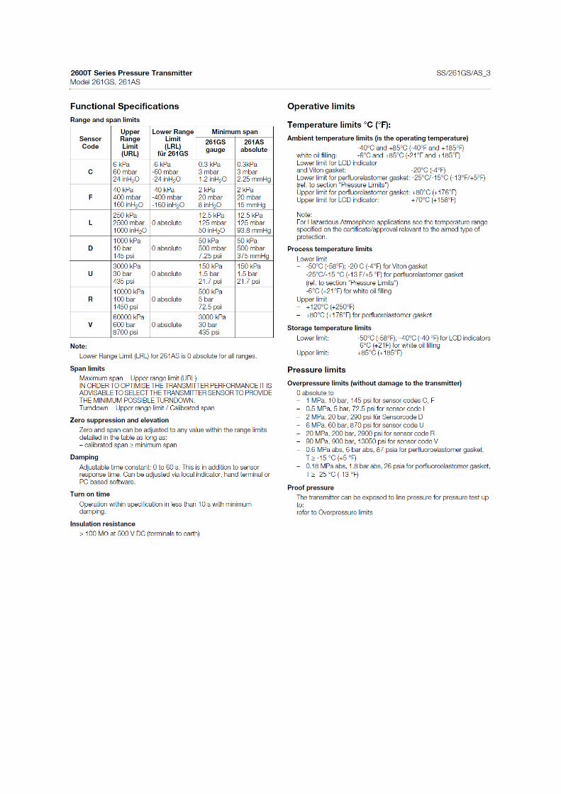

Appendix E Technical drawings of 25-HA-113 twisted tube


Appendix F Technical drawings of 25-HA-113 double helix

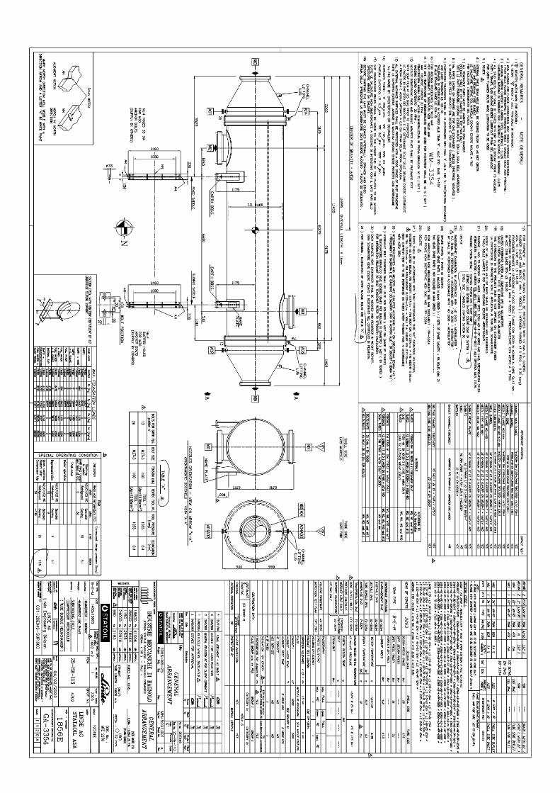

Appendix G Thermodynamic properties of HC gas

The properties are evaluated at for the following HC gas composition CH4 53,2% C2H6 29,0% C3H8 0,4% N2 17,4%


Appendix H Correction of thermodynamic properties
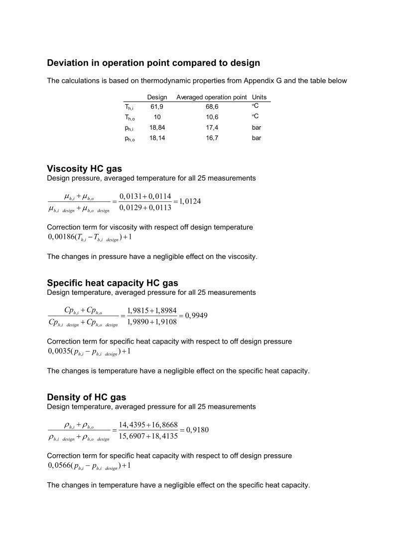
Deviation in operation point compared to design The calculations is based on thermodynamic properties from Appendix G and the table below
Design Averaged operation point UnitsTh,i 61,9 68,6 ºC
Th,o 10 10,6 ºC
ph,i 18,84 17,4 barph,o 18,14 16,7 bar
Viscosity HC gas Design pressure, averaged temperature for all 25 measurements
,
_
,
,_,
0,0131 0,0114 1,01240,0129 0,0113
h i h o
h i design h o design
μ μμ μ
+ += =
+ +
Correction term for viscosity with respect off design temperature
, , _0,00186( ) 1h i h i designT T− + The changes in pressure have a negligible effect on the viscosity. Specific heat capacity HC gas Design temperature, averaged pressure for all 25 measurements
, ,
, ,_ _
1,9815 1,8984 0,99491,9890 1,9108
h i h o
h i design h o design
Cp CpCp Cp
+ += =
+ +
Correction term for specific heat capacity with respect to off design pressure
, , _0,0035( ) 1h i h i designp p− + The changes is temperature have a negligible effect on the specific heat capacity. Density of HC gas Design temperature, averaged pressure for all 25 measurements
, ,
, _ _,
14,4395 16,8668 0,918015,6907 18,4135
h i h o
h i design h o design
ρ ρρ ρ
+ += =
+ +
Correction term for specific heat capacity with respect to off design pressure
, , _0,0566( ) 1h i h i designp p− + The changes in temperature have a negligible effect on the specific heat capacity.

Appendix I TEMA specification sheets printed from HTRI

CHAPTER 3: SPECIFICATION SHEET FOR TWISTED TUBE HEAT EXCHANGER

CHAPTER 6: SPECIFICATION SHEET FOR CONVENTIONAL HEAT EXCHANGER

CHAPTER 6: SPECIFICATION SHEET FOR DOUBLE HELIX HEAT EXCHANGER