investigation report s i
TRANSCRIPT

U.S. Chemical Safety and Hazard Investigation Board
Hydrogen Sulfide Release at Aghorn Operating Waterflood Station
Odessa, Texas | Incident Date: October 26, 2019 | No. 2020-01-I-TX
Investigation Report Published: May 2021
SAFETY ISSUES: • Nonuse of Personal H2S Detector • Nonperformance of Lockout /
Tagout • Confinement of H2S Inside Pump
House • Lack of Safety Management
Program • Nonfunctioning H2S Detection
and Alarm System • Deficient Site Security

1
Investigation Report
U.S. Chemical Safety and
Hazard Investigation Board
The mission of the U.S. Chemical Safety and Hazard Investigation Board (CSB) is to drive chemical safety change through independent investigations
to protect people and the environment.
The CSB is an independent federal agency charged with investigating, determining, and reporting to the public in writing the facts, conditions, and circumstances and the cause or probable cause of any accidental chemical release resulting in a fatality, serious injury, or substantial property damages.
The CSB issues safety recommendations based on data and analysis from investigations and safety studies. The CSB advocates for these changes to prevent the likelihood or minimize the consequences of accidental chemical releases.
More information about the CSB and CSB products can be accessed at www.csb.gov or obtained by contacting:
U.S. Chemical Safety and Hazard Investigation Board 1750 Pennsylvania Ave. NW, Suite 910 Washington, DC 20006 (202) 261-7600
The CSB was created by the Clean Air Act Amendments of 1990, and the CSB was first funded and commenced operations in 1998. The CSB is not an enforcement or regulatory body. No part of the conclusions, findings, or recommendations of the Board relating to any accidental release or the investigation thereof shall be admitted as evidence or used in any action or suit for damages arising out of any matter mentioned in such report. 42 U.S.C. § 7412(r)(6)(G).

2
Investigation Report
Contents
FIGURES ............................................................................................................................................... 4
ABBREVIATIONS ................................................................................................................................... 6
EXECUTIVE SUMMARY ......................................................................................................................... 7
1 FACTUAL INFORMATION ............................................................................................................. 10
1.1 The Aghorn Facility ................................................................................................................... 10 1.1.1 Incident Location ............................................................................................................... 10 1.1.2 The Waterflooding Process ............................................................................................... 10 1.1.3 Foster D Waterflood Station Process Flow ........................................................................ 11 1.1.4 Pump House ...................................................................................................................... 12 1.1.5 Pump Equipment ............................................................................................................... 15 1.1.6 Lockout / Tagout ............................................................................................................... 17 1.1.7 Site Security ....................................................................................................................... 18
1.2 Aghorn Personnel ..................................................................................................................... 20 1.2.1 Pumper A and Pumper B ................................................................................................... 20 1.2.2 Pumper Responsibilities ..................................................................................................... 21
1.3 H2S Hazard and Detection ........................................................................................................ 21 1.3.1 H2S Characteristics and Toxicity ........................................................................................ 21 1.3.2 Toxic Gas Detection Systems at the Foster D Waterflood Station ..................................... 21
1.4 Incident Scene .......................................................................................................................... 23
1.5 Weather at Time of Incident .................................................................................................... 26
1.6 H2S and Water Injection Wells in the United States ................................................................. 26
2 INCIDENT DESCRIPTION .............................................................................................................. 29
2.1 Initial Alarm Notification........................................................................................................... 29
2.2 Pumper Response ..................................................................................................................... 29
2.3 Arrival of Pumper’s Spouse ...................................................................................................... 30
2.4 Emergency Response ............................................................................................................... 30
3 INCIDENT ANALYSIS .................................................................................................................... 34
3.1 Nonuse of Personal H2S Detector ............................................................................................. 34
3.2 Nonperformance of Lockout / Tagout ...................................................................................... 35
3.3 Confinement of H2S Inside Pump House .................................................................................. 35
3.4 Lack of Safety Management Program ...................................................................................... 37
3
Investigation Report
3.4.1 Opportunity for Improved Hazard Communication by Regulators .................................... 37
3.5 Nonfunctioning H2S Detection and Alarm System .................................................................... 38 3.5.1 Aghorn H2S Detection and Alarm System .......................................................................... 38 3.5.2 Improved System Design ................................................................................................... 39
3.6 Deficient Site Security............................................................................................................... 40
4 CONCLUSIONS ............................................................................................................................ 43
4.1 Findings .................................................................................................................................... 43
4.2 Probable Cause ......................................................................................................................... 45
5 RECOMMENDATIONS.................................................................................................................. 46
5.1 Aghorn Operating Inc. .............................................................................................................. 46
5.2 Occupational Safety and Health Administration (OSHA) .......................................................... 47
5.3 Railroad Commission of Texas .................................................................................................. 47
6 KEY LESSONS FOR THE INDUSTRY ................................................................................................ 48
7 REFERENCES ............................................................................................................................... 49
APPENDIX A—CAUSAL ANALYSIS (ACCIMAP) ...................................................................................... 51

4
Investigation Report
Figures Figure 1. Aghorn Foster D waterflood station in Odessa, Texas. ........................................................................ 10
Figure 2. Simplified illustration of the Aghorn waterflooding process ................................................................ 11
Figure 3. Illustration of the Foster D waterflood station ...................................................................................... 12
Figure 4. Depiction of pump house ...................................................................................................................... 13
Figure 5. Control room layout .............................................................................................................................. 14
Figure 6. Video still showing bay door positions and released produced water .................................................. 14
Figure 7. Major components of a plunger pump .................................................................................................. 15
Figure 8. A spare ceramic plunger ....................................................................................................................... 16
Figure 9. View of a plunger pump’s main components ....................................................................................... 16
Figure 10. Photos of Pump #1 cradle and visible broken plunger pieces ............................................................. 17
Figure 11. Aghorn waterflood station security ..................................................................................................... 19
Figure 12. Warning signs to the left of the gate to the facility from the public road ........................................... 19
Figure 13. Warning signs and interior fence surrounding the waterflood station ................................................ 20
Figure 14. Locations of the eight H2S point detectors at the waterflood station .................................................. 22
Figure 15. Image of an H2S point detector ........................................................................................................... 23
Figure 16. Light designed to illuminate when a dangerous concentration of H2S is detected ............................. 23
Figure 17. Image of Pump #1 taken on Saturday, October 27, 2019 ................................................................... 25
Figure 18. Suction and discharge valve positions of Pump #1, and approximate location where Pumper A and his spouse were found ........................................................................................................................................... 25
Figure 19. Position of the discharge (left) and suction (right) valves on Pump #1 .............................................. 26
Figure 20. Prominent U.S. oil and gas regions ..................................................................................................... 27
Figure 21. Oil and gas production in the United States ........................................................................................ 27
Figure 22. PLC screen displaying Pump #1 crankcase oil level alarm ................................................................ 30
Figure 23. Location of the incident command post (red star) and incident location (gold star) .......................... 31

5
Investigation Report
Figure 24. Images of Pump #1 ............................................................................................................................. 32
Figure 25. Location of final valve closure that stopped the release of water from the failed Pump #1 ............... 33
Figure 26. Photos showing bay door positions ..................................................................................................... 36
Figure 27. An alternative detection system design ............................................................................................... 39

6
Investigation Report
Abbreviations CFR Code of Federal Regulations
CSB U.S. Chemical Safety and Hazard Investigation Board
EIA U.S. Energy Information Administration
H2S hydrogen sulfide
IDLH immediately dangerous to life or health
mph miles per hour
NIOSH National Institute for Occupational Safety and Health
OSHA Occupational Safety and Health Administration
PLC programmable logic controller
PPE personal protective equipment
ppm parts per million
psig pounds per square inch gauge
SCBA self-contained breathing apparatus
SSW south south west
SW south west

7
Investigation Report
Executive Summary On October 26, 2019, an Aghorn Operating Inc. (Aghorn) employee, Pumper A, responded to a pump oil level alarm at Aghorn’s Foster D waterflood station in Odessa, Texas. The pump (called Pump #1) was located in a building called a pump house. In response to the alarm, Pumper A worked to isolate the pump from the process by closing the pump’s discharge valve and partially closing the pump’s suction valve. Pumper A did not first perform Lockout / Tagout to isolate Pump #1 from energy sources before performing work on the pump. At some point on the night of the incident, the pump automatically turned on, and water containing hydrogen sulfide (H2S), a toxic gas, released from the pump. The CSB found post-incident that the pump had a broken plunger from which the water and H2S released. Due to the limitations of the available evidence, the CSB was unable to determine whether the pump failure and loss of containment of the produced water (1) occurred before Pumper A arrived at the facility, or (2) occurred when the pump energized while Pumper A was closing valves to isolate the pump.
Pumper A was fatally injured from his exposure to the released H2S.
Subsequently, the spouse of Pumper A gained access to the waterflood station and searched for Pumper A. During her search efforts, she also was exposed to the released H2S and was fatally injured.
Odessa Fire Rescue and the Ector County Sheriff’s Office responded to the incident. Federal agencies that investigated the incident include the Occupational Safety and Health Administration (OSHA) and the U.S. Chemical Safety and Hazard Investigation Board (CSB).
The CSB’s investigation identified the safety issues below.
Safety Issues
The investigation evaluated the following safety issues:
• Nonuse of Personal H2S Detector. Pumper A was not wearing his personal H2S detection device upon entering the waterflood station on the night of the incident, and there is no evidence that Aghorn management required the use of these devices. (Section 3.1)
• Nonperformance of Lockout / Tagout. At the time of the incident, Aghorn did not have any written Lockout / Tagout policies or procedures. Pumper A did not perform Lockout / Tagout to deenergize Pump #1 before performing work on it. The automatic activation of the pump allowed water containing H2S to release from the pump. (Section 3.2)
• Confinement of H2S Inside Pump House. The pump house could be ventilated by two bay doors on the east side of the pump house, exhaust fans on the west wall opposite of the bay doors, and natural vents on each of the four outside walls. Due to the limitations of the available evidence, the CSB was unable to confirm whether the exhaust fans were operational at the time of the incident. On the night of the incident, the bay doors were approximately 60% open. The available ventilation methods did not adequately ventilate toxic H2S gas from the building during the incident, contributing to the high H2S levels to which Pumper A and his spouse were exposed. (Section 3.3)
8
Investigation Report
• Lack of Safety Management Program. The CSB requested from Aghorn “all written policies and procedures used by Aghorn Operating.” Aghorn’s response included: 1) a cell phone use policy, 2) an alarm call out procedure, 3) a Lockout / Tagout policy and procedure that was created post-incident, and 4) a pamphlet on H2S hazards. Aghorn had no additional formal company safety or operational policies or procedures. (Section 3.4)
• Nonfunctioning H2S Detection and Alarm System. The pump house was equipped with an H2S detection and alarm system. However, the H2S control panel did not receive signals from the internal and external detection sensors at the facility, and, therefore, did not trigger either of the two H2S alarms on the night of the incident. (Section 3.5)
• Deficient Site Security. As per Aghorn’s informal policy, when an Aghorn employee is working at the facility, the access gates are normally left unlocked. The unlocked gates allowed Pumper A’s spouse to drive directly to the waterflood station and enter the pump house, where she was exposed to toxic H2S gas. (Section 3.6)
Probable Cause
The CSB determined that the probable cause of the incident was Aghorn’s failure to enforce operator use of personal H2S detectors when in the vicinity of equipment or facilities with the potential to release H2S, and Aghorn’s failure to develop, train on, and enforce Lockout / Tagout procedures that led to Pumper A performing work on a pump while it was still energized. Contributing to the incident was Aghorn’s facility physical and operational design, which did not allow for adequate ventilation of the toxic H2S gas inside the pump house, and Aghorn’s deficient safety management program. Likely also contributing to the incident was Aghorn’s failure to maintain and properly configure the site H2S detection and alarm system. Contributing to the severity of the incident was Aghorn’s poor site security that allowed Pumper A’s spouse to gain access to the facility.
Recommendations
To Aghorn Operating Inc.
For all waterflood stations where the potential exists to expose workers or non-employees to H2S concentrations at or above 10 ppm, mandate the use of personal H2S detection devices as an integral part of every employee or visitor personal protective equipment (PPE) kit prior to entering the vicinity of the facility. Ensure detector use is in accordance with manufacturer specifications.
For all Aghorn facilities, develop a site-specific, formalized and comprehensive Lockout / Tagout program, to include policies, procedures, and training, to protect workers from energized equipment hazards, such as exposure to H2S. Ensure the program meets the requirements outlined in 29 CFR 1910.147 and includes energy control procedures, training, and periodic inspections.
For all waterflood stations where the potential exists to expose workers to H2S concentrations at or above 10 ppm, commission an independent and comprehensive analysis of each facility design vis-à-vis ventilation and mitigation systems to ensure that, in the event of an accidental release, workers are protected from exposure to toxic gas levels.
For all waterflood stations where the potential exists to expose workers or non-employees to H2S concentrations at or above 10 ppm, develop and demonstrate the use of a safety management program that includes a focus on

9
Investigation Report
protecting workers and non-employees from H2S. This program should include risk identification, assessment, mitigation, and monitoring of design, procedures, maintenance and training related to H2S. This program must be in compliance with 29 CFR 1910.1000 – Air Contaminants and 29 CFR 1910.147 – The Control of Hazardous Energy (Lockout / Tagout).
For all waterflood stations where the potential exists to expose workers to H2S concentrations at or above 10 ppm, ensure the H2S detection and alarm systems are properly maintained and configured, and develop site-specific detection and alarm programs and associated procedures based on manufacturer specifications, current codes, standards, and industry good practice guidance. The program must address installation, calibration, inspection, maintenance, training and routine operations.
For all waterflood stations where the potential exists to expose workers or non-employees within the perimeter of the facility to H2S concentrations at or above 10 ppm, ensure that the H2S detection and alarm system designs employ multiple layers of alerts unique to H2S, such as with the use of both audible and visual mediums, so that workers and non-employees within the perimeter of the facility would be alerted to a significant release. The system design must meet manufacturer specifications, current codes, standards, and industry good practice guidance.
For all waterflood stations where the potential exists to expose non-employees to H2S concentrations at or above 10 ppm, develop and implement a formal, written, site-specific security program to prevent unknown and unplanned entrance of those not employed by Aghorn, starting with a requirement for employees to lock access gates upon entering and departing the facility.
Occupational Safety and Health Administration (OSHA)
Issue a safety information product (such as a safety bulletin or safety alert) that addresses the requirements for protecting workers from hazardous air contaminants and from hazardous energy.
Railroad Commission of Texas
Develop and send a Notice to Operators to all oil and gas operators that fall under the jurisdiction of the Railroad Commission of Texas that describes the safety issues described in this report, including:
1. Nonuse of Personal H2S Detector
2. Nonperformance of Lockout / Tagout
3. Confinement of H2S Inside Pump House
4. Lack of Safety Management Program
5. Nonfunctioning H2S Detection and Alarm System
6. Deficient Site Security
10
Investigation Report
1 Factual Information This section details the facts gathered by the CSB investigation team.
1.1 The Aghorn Facility
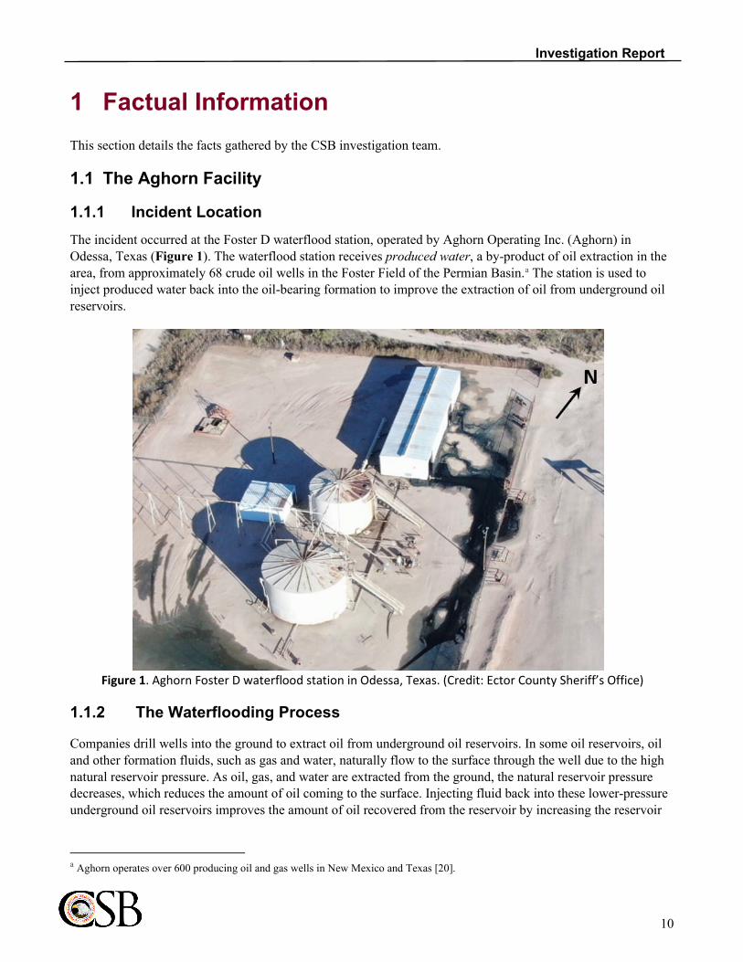
1.1.1 Incident Location The incident occurred at the Foster D waterflood station, operated by Aghorn Operating Inc. (Aghorn) in Odessa, Texas (Figure 1). The waterflood station receives produced water, a by-product of oil extraction in the area, from approximately 68 crude oil wells in the Foster Field of the Permian Basin.a The station is used to inject produced water back into the oil-bearing formation to improve the extraction of oil from underground oil reservoirs.
Figure 1. Aghorn Foster D waterflood station in Odessa, Texas. (Credit: Ector County Sheriff’s Office)
1.1.2 The Waterflooding Process
Companies drill wells into the ground to extract oil from underground oil reservoirs. In some oil reservoirs, oil and other formation fluids, such as gas and water, naturally flow to the surface through the well due to the high natural reservoir pressure. As oil, gas, and water are extracted from the ground, the natural reservoir pressure decreases, which reduces the amount of oil coming to the surface. Injecting fluid back into these lower-pressure underground oil reservoirs improves the amount of oil recovered from the reservoir by increasing the reservoir
a Aghorn operates over 600 producing oil and gas wells in New Mexico and Texas [20].

11
Investigation Report
pressure. Aghorn uses a technique called waterflooding, which is performed by pumping pressurized produced water to increase the pressure in underground oil reservoirs [1] [2].
Figure 2 illustrates the Aghorn oil extraction and waterflooding processes. Large pumps, called pump jacks, extract oil from underground oil reservoirs and transfer the oil to a tank batterya through pipes. At the tank battery, the oil is stored in large tanks, where produced water separates from the oil.b Produced water typically contains other components, including hydrogen sulfide (H2S), a toxic gas known to be present in oil and gas reservoirs in the area.c After it is separated from the oil, other pipes transfer the produced water from several tank batteries to a waterflood station. The waterflood station pumps the produced water back into the oil reservoir.
1.1.3 Foster D Waterflood Station Process Flow Figure 3 illustrates the process and directional flow (dark blue arrows) at the Foster D waterflood station, which comprises an inlet building, a suction tank, a pump house, and a reserve tank.
a A tank battery is a “group of tanks that are connected to receive crude oil production from a well or a producing lease” [19]. b The density difference between water (more dense) and oil (less dense) causes water to separate from the mixture and settle at the
bottom of the storage tanks, while the oil floats on top of the water layer. c Tests of produced water from one of the wells that feeds produced water to the waterflood station showed the water contained dissolved
H2S gas.
Figure 2. Simplified illustration of the Aghorn waterflooding process. (Credit: CSB)

12
Investigation Report
The produced water from several tank batteries first enters the waterflood station at the inlet building. The produced water is then routed to a temporary storage tank called the suction tank. From there, the water flows through a pipe to the pump house, where positive displacement pumps pressurize the water to approximately 900 pounds per square inch gauge (psig). The produced water then exits the facility through a series of pipes and is injected back into the oil reservoir. The reserve tank is typically used as an overflow during maintenance and is not part of the normal process flow.
Figure 3. Illustration of the Foster D waterflood station. (Credit: CSB)
1.1.4 Pump House There are three positive displacement pumps inside the pump house, numbered 1 through 3. Aghorn runs up to two pumps simultaneously. The third pump is used as a spare. At the time of the incident, only two pumps were installed (Pump #1 and Pump #3); the third pump (Pump #2) was removed for maintenance. Figure 4 shows the pump house layout and the directional flow of the produced water (dark blue arrows).
The waterflood station's control room is in the northeast corner of the pump house (Figure 4). A programmable logic controller (PLC) monitors all process equipment on a control board inside the control room (Figure 5) and automatically operates pumps based on the liquid level in the suction tank. The power switch on the control board has three positions: “hand,” meaning the pump is turned on manually by a person; “off,” which turns the pump off; and “automatic,” which causes the pumps to be controlled by the PLC. Aghorn communicated to the CSB that at the time of the incident, the PLC was programmed to turn on Pump #1 and Pump #3 when the liquid level in the suction tank reached a preset level. According to Aghorn, when the liquid reached the preset level, Pump #1 would automatically turn on and, approximately 15 seconds later, Pump #3 would automatically turn on.
Employees use a touch pad on the PLC to adjust operational parameters and alarm set points. In the event operating conditions deviate from the normal range and reach an alarm set point, the PLC system activates an alarm. An automatic phone notification system then calls the pumper on duty to alert them of the deviation.

13
Investigation Report
The waterflood station is also equipped with an H2S detection and alarm system. If activated, a red, rotating beacon light will illuminate on top of the pump house, and an automatic phone notification system will engage and notify the pumper on duty of the H2S release.
The pump house is equipped with large bay doors, exhaust fans on the west wall opposite of the bay doors, and natural vents on each of the four outside walls. The bay doors and exhaust fans were the primary means of ventilating the pump house. Aghorn did not have an associated procedure to ensure ventilation of the pump house. Via an interview with an Aghorn employee and written communication with the company, CSB investigators were informed that these overhead doors were typically kept between 50 percent and 75 percent open (Figure 6). Due to the limitations of the available evidence, the CSB was unable to confirm whether the exhaust fans were operational at the time of the incident.
Aghorn communicated to the CSB that it operates four waterflood stations using positive displacement pumps. In three of the stations, the pumps are installed in a building and in one of the stations the pumps are installed outdoors. Aghorn communicated to the CSB that it acquired the three waterflood stations with pumps installed inside of a pump building from major oil companies including Kerr-McGee, Conoco Phillips, and Chevron.
Figure 4. Depiction of pump house. (Credit: CSB)

14
Investigation Report
Figure 5. Control room layout. (Credit: CSB)
Figure 6. Video still showing bay door positions and released produced water. (Credit: Ector County Sheriff’s Office)

15
Investigation Report
1.1.5 Pump Equipment
1.1.5.1 Plunger Pump Pump #1 is a National-Oilwell type J-275 quintaplex plunger pump. The pump is a positive displacement pump. Shown in Figure 7, the primary components of plunger pumps are
- the motor, which provides the driving force for the pump;
- the gear end, which converts the rotational motion of the motor to the horizontal motion of the pump;
- the cradle, an open section in the pump between the fluid end and the gear end; and
- the fluid end, which contains valving and seals required for the pump to pressurize water.
Between the gear end and the fluid end, inside the cradle, five ceramic plungers (Figure 8) pressurize the produced water. The gear end pulls the plungers into and out of the fluid end, which draws water from the suction tank and pressurizes the water into the discharge piping [3, p. 3]. The stuffing box is designed to seal around the plunger and prevent the produced water from leaking out of the fluid end. Shown in Figure 9, the stuffing box contains the components required to seal around the plunger to prevent any leaks. Valves inside the fluid end (orange highlight) open to allow water in from the suction line (light blue arrows), the plunger presses on the water, and another valve opens to allow the pressurized water to flow into the discharge line (dark blue arrows). Pump #1 had a maximum discharge pressure of 1,020 psig and was usually run at around 900 psig.
Figure 7. Major components of a plunger pump. (Credit: CSB)

16
Investigation Report
Figure 8. A spare ceramic plunger. (Credit: CSB)
Figure 9. View of a plunger pump’s main components. (Credit: CSB)
1.1.5.2 Pump #1 Maintenance Maintenance was last performed on Pump #1 on October 4, 2019 to troubleshoot a packing leak. On that occasion, the entire fluid end of the pump was assessed including pulling all plungers, replacement of all suction and discharge valves, replacement of all wiper boxes, seals and gaskets and repacking and re-installation of all five ceramic plungers.

17
Investigation Report
1.1.5.3 Pump #1 Inspection The CSB inspected Pump #1 after the incident. The inspection found that one of the pump's plungers had backed off its threaded connection to the gear end, and the ceramic was shattered. The fragments of the plunger could be seen in the bottom of the cradle (Figure 10). The inspection also revealed that the discharge valve handle for Pump #1 was in a position indicating approximately 95 percent closed and the position indicator on the suction valve for Pump #1 was about 50 percent closed (Figure 18 and Figure 19).
Figure 10. Photos of Pump #1 cradle and visible broken plunger pieces. (Credit: CSB)
1.1.6 Lockout / Tagout At the time of the incident, Aghorn did not have any written Lockout / Tagout policies or procedures. In interviews, three Aghorn employees—including the vice president and two production foremen, one of whom had previously been a pumper—explained that the Aghorn Lockout / Tagout practice was communicated on-the-job only. One Aghorn employee described to the CSB the following Aghorn Lockout / Tagout practice to isolate electricity from the pump:
1) Turn power switch on control panel to “off”
2) Turn off switch at main electric service disconnect
3) Place orange flag on main electric service disconnect switch
4) Turn power switch on control panel to “hand”
5) Check to ensure pump does not turn on
6) If pump does not turn on, turn power switch on control panel back to “off”
Neither the switch on the control panel nor the main electric service disconnect was in the “off” position for Pump #1 on the night of the incident.

18
Investigation Report
Aghorn did not provide the CSB with sufficient records for CSB investigators to determine to what extent Pumper A was trained on the verbal Lockout / Tagout practice, however notes filled out by Pumper A for a pump isolation as recent as September 2019 indicate that he had previously performed the Lockout / Tagout practice described above. Pumper A did not Lockout / Tagout Pump #1 before closing the pump’s discharge valve and partially closing the suction valve on the night of the incident.
1.1.7 Site Security Site security at the facility consists of a gate at the entrance from the public road, a barbed wire fence around the perimeter, and a chain link fence topped with barbed wire around the waterflood station (Figure 11). Immediately to the left of the gate to the facility near the public road, signs list several warnings, including warnings about the potential for H2S gas to be present (Figure 12). Additional signs, installed to the left the gate of the interior chain link fence topped with barbed wire, also warn of the potential presence of H2S (Figure 13). Many of the H2S warning signs were corroded. The signs were likely not non-corrosive, were not reflective, were not lit, and were likely difficult to read under low light conditions. Further, vehicles passing through these two open gates in night conditions may not have seen the signs at all, as they would not have been in the direct line of sight. For the internal fence, when the gates were open, a vehicle’s headlights would not have been facing the signs upon entry. For the external fence, the vehicle’s headlights would have only faced the signs if they arrived from the east.
Aghorn told the CSB they expect the waterflood station access gates to be locked each day after employees complete their tasks. While employees are present at facilities, the gates are typically left open and unlocked. On the night of the incident, both the gate and the chain link fence were left open since Pumper A was working in the pump house.

19
Investigation Report
Figure 11. Aghorn waterflood station security. (Credit: CSB)
Figure 12. Warning signs to the left of the gate to the facility from the public road. (Credit: CSB)

20
Investigation Report
1.2 Aghorn Personnel
The following section provides roles and responsibilities of Aghorn personnel directly involved in the events leading up to the incident, but excluding the response.
1.2.1 Pumper A and Pumper B Personnel who work regularly at the waterflood station are called pumpers. This report refers to Pumper A and Pumper B. Pumper B was the lead pumper, and Pumper A was the relief pumper for the waterflood station. On October 26, 2019, Pumper B was on vacation, and therefore Pumper A was working in his role as the relief pumper on the day of the incident. Pumper A had been employed by Aghorn for over 11 years.
Aghorn communicated the following to the CSB:
Pumper B trained Pumper A at the waterflood station for approximately 4 months on a full-time basis in 2008. Then, for a period of fourteen (14) months beginning in 2009, Pumper A served as the lead pumper for the waterflood station. […] As the relief pumper, Pumper A would have been at the waterflood station two to three days every week[.]
Figure 13. Warning signs and interior fence surrounding the waterflood station. (Credit: CSB)

21
Investigation Report
1.2.2 Pumper Responsibilities The pumper visits the waterflood station twice per day. During the first visit, the pumper records water flow meter readings, tank levels, and pump status. Aghorn informed the CSB that the pumper is also expected to check on the facility's equipment, inspect fluid levels, and observe for any abnormal noises, vibrations, or other malfunctions. The pumper then inspects the facility's perimeter before continuing his or her rounds at other locations. The pumper returns to the waterflood station at the end of the day—the pumper’s second visit—and conducts a short final inspection before locking the facility down for the night. As per routine, Pumper A performed both the first and second visit to the waterflood station on October 26, 2019.
When a deviation from normal operation at the waterflood station triggers an alarm, the phone system automatically calls the pumper’s phone, alerting him or her to the anomalous event. When this occurs, Aghorn expects the pumper to acknowledge the alarm and immediately go to the facility to assess the situation. The pumper is then responsible for making any simple repairs or securing the site and coordinating larger repairs by a third party.
1.3 H2S Hazard and Detection
1.3.1 H2S Characteristics and Toxicity H2S is a colorless, flammable gas that has an odor similar to rotten eggs [4]. H2S gas is heavier than air and will collect along the ground or in low-lying areas. People exposed to H2S for an extended period or at high concentrations can lose their ability to smell the gas, a condition called olfactory fatigue. For this reason, the Occupational Safety and Health Administration (OSHA) warns that the sense of smell should not be used as a detection method. According to the National Institute for Occupational Safety and Health (NIOSH), a level of 100 parts per million (ppm) is immediately dangerous to life or health (IDLH) [5].a H2S levels greater than 500 ppm can cause a person to collapse within five minutes. When levels exceed 700 ppm, collapse can occur within one or two breaths [6]. The NIOSH H2S recommended exposure limit is 10 ppm.
Autopsy reports indicate that both Pumper A and his spouse were fatally injured by acute H2S inhalation.
1.3.2 Toxic Gas Detection Systems at the Foster D Waterflood Station
1.3.2.1 Fixed H2S Gas Detection and Alarm System The waterflood station was equipped with an H2S detection and alarm system, which Aghorn stated to the CSB was designed to initiate an alarm when the system detected H2S above a specific concentration. To detect the gas, the waterflood station used eight point detectors: six around the perimeter of the tanks and buildings, and two inside the pump house (Figure 14, Figure 15).b When any one or more detectors sensed a concentration of H2S gas above a specified level, the system was designed to send a signal to the H2S control panel in the control room. The control panel would then activate two separate alarms: (1) an alarm connected to the phone system, which would call the pumper on duty and alert him or her to the dangerous atmosphere at the facility, and (2) a
a NIOSH chooses IDLH values (1) to ensure that a worker can escape from a given contaminated environment in the event of failure of
respiratory protection equipment and (2) to indicate a maximum level above which only a highly reliable breathing apparatus, providing maximum worker protection, is permitted.
b These sensors are normally installed in locations that could have a hazardous vapor present [18].

22
Investigation Report
rotating red beacon light at the top of the pump house to provide a visual cue that there was a dangerous atmosphere at the facility (Figure 16). The alarm system did not incorporate an auditory alert.
CSB investigators asked emergency responders and Aghorn personnel who responded to the incident if they heard or saw any alarms, such as an illuminated light on top of the pump house. None of the emergency responders or Aghorn personnel told the CSB that they saw the light illuminated during the emergency response. When activated, the beacon light is designed to continuously rotate 360 degrees and display an unblinking red light.
The CSB tested the H2S alarm system after the incident. Results showed that none of the working detectors communicated with the alarm’s control panel located in the control room. Some of the facility’s detectors were set to a testing mode, which prevented them from sending an alarm signal. For the other sensors that were set to the correct mode, no signal was received by the control panel. Results also indicated that, with a properly configured H2S detection and alarm system, a test signal from the control panel was successful in illuminating the beacon light on the top of the building. Had the sensors and sensor element of the system been operational, the alarm element of the system would have been successful. The CSB requested from Aghorn all maintenance and calibration records for the H2S detection and alarm system. Aghorn responded to the CSB stating that it did not locate any responsive documents.
Figure 14. Locations of the eight H2S point detectors at the waterflood station. (Credit: CSB)

23
Investigation Report
1.3.2.2 H2S Personal Gas Detector Aghorn supplied its employees with personal H2S gas detectors to be worn on their person. No personal H2S gas detector was found on Pumper A after the incident. Emergency responders found a personal H2S detector in Pumper A’s work truck. When they removed it from the vehicle, the device was emitting an audible alarm, meaning the detector had been exposed to elevated levels of H2S.
Aghorn provided H2S training to its employees on February 13, 2019. Aghorn communicated to the CSB that the employees “had been trained not only on the properties of H2S gas, including odor, but also in the dangers of working in and around H2S and the importance of wearing a personal H2S monitor.” The employees also performed a written test on H2S hazards, which covered topics including the concentrations and duration that H2S can be detected by sense of smell, symptoms of H2S exposure, and use of personal H2S monitors and respiratory protection.
At the time of the incident, Aghorn did not have a formal policy requiring employees to wear personal H2S detectors while at waterflood stations.
1.4 Incident Scene
Post-incident, the scene was found with the following conditions:
1. Emergency responders began to smell H2S after they entered the gate from the public road, about half way between the public road and the pump house. When emergency responders neared the pump house, there was an “overwhelmingly strong smell” of H2S;
2. Both the road access gate and the gate of the interior chain link fence topped with barbed wire were open;
Figure 15. Image of an H2S point detector. (Credit: CSB)
Figure 16. Light designed to illuminate when a dangerous concentration of H2S is detected. (Credit: CSB)

24
Investigation Report
3. The H2S warning signs to the left of the gate entrance at the public road were corroded;
4. Produced water was observed spilling out of Pump #1 (Figure 17). Water was also present exterior to the pump house (Figure 6). Such water presence is abnormal at the facility and indicative of an equipment malfunction;
5. Pump #1 was running when emergency responders arrived at the scene;
6. A high concentration of H2S gas was inside and near the pump house;
7. The red, rotating beacon light on top of the pump house that is designed to activate when H2S is detected was not activated or illuminated;
8. The bay doors were approximately 60% open;
9. The control system power switch for Pump #1 was in the “automatic” position, meaning it was configured to be controlled by the PLC;
10. The main power electric service disconnect switch for Pump #1 was in the “on” position;
11. The discharge valve handle for Pump #1 was in a position indicating approximately 95 percent closed (Figure 18 and Figure 19). Aghorn communicated to the CSB that “the discharge valve is a quarter turn ball valve and, at 95 percent closed, the valve would have effectively been 100 percent closed;”a
12. The position indicator on the suction valve for Pump #1 was about 50 percent closed (Figure 18 and Figure 19);
13. Pumper A’s personal H2S detector was found in his work truck. It was in an alarm state, meaning it had detected dangerous levels of H2S;
14. Pumper A was found deceased near the suction valve of Pump #1 (Figure 18); and
15. Pumper A’s spouse was found deceased next to the body of Pumper A.
a From an Aghorn communication to the CSB dated April 21, 2021.

25
Investigation Report
Figure 17. Image of Pump #1 taken on Saturday, October 27, 2019. (Credit: Ector County Sheriff)
Figure 18. Suction and discharge valve positions of Pump #1, and approximate location where Pumper A and his spouse were found. (Credit: CSB)

26
Investigation Report
Figure 19. Position of the discharge (left) and suction (right) valves on Pump #1. (Credit: CSB)
1.5 Weather at Time of Incident
Data from the Odessa-Schlemeyer Field Station indicates that on October 26, 2019 at 6:53 p.m., the temperature was 71°F, and a 12 mile per hour (mph) wind was blowing from the southwest (SW) direction. When emergency responders arrived at approximately 10:00 p.m., the temperature was about 56°F, and a 6 mph wind was blowing from the south south west (SSW) direction [7].
1.6 H2S and Water Injection Wells in the United States
H2S forms naturally in some geologic formations from decomposing underground organic matter, such as decaying plant matter [8, p. 17]. H2S is found in underground formations throughout the United States, and is prevalent in the Permian Basin, an oil and gas basin located in west Texas and southeast New Mexico (Figure 20). A 2017 study found that over 85% of the natural gas produced from the Permian Basin contains greater than 100 ppm H2S [9]. The U.S. Energy Information Administration (EIA) March 2021 Drilling Productivity Report indicates that U.S. oil production is highest from the Permian Basin—at over 4,000 barrels per day—and natural gas production is second highest from the Permian Basin—at almost 18,000 million cubic feet per day (Figure 21).

27
Investigation Report
Figure 20. Prominent U.S. oil and gas regions. (Credit: EIA [10])
Figure 21. Oil and gas production in the United States. (Credit: EIA [10])
Nationwide, there are about 115,000 injection wells used for enhanced oil recovery. Most of these wells are water injection wells that re-inject produced water back into the formation [11, p. 30]. H2S is prevalent throughout oil and gas formations in the United States, and the waterflood stations that pump high-pressure water into these thousands of injection wells have the potential to release toxic H2S in the event of equipment failure.

28
Investigation Report
According to a database managed by the Railroad Commission of Texas, a search conducted in March 2021 by the Commission showed that, in Texas alone, there are 4,886 enhanced oil recovery injection wells that are authorized to inject H2S.

29
Investigation Report
2 Incident Description 2.1 Initial Alarm Notification
During the evening of October 26, 2019 after Pumper A’s second visit to the waterflood station, at 6:38 p.m., the PLC triggered a Pump #1 crankcase oil level alarm on the control board. Five minutes later, at 6:43 p.m., the phone system sent an automated audio message to Pumper A, which stated, “Alarm Alert Condition 3. Please acknowledge.” Alarm Alert Condition 3 indicates a pump malfunction of some kind. To determine the precise alarm, Pumper A was then required to go to the waterflood station and access the PLC in the control room to obtain more detailed information about the alarm. Pumper A then acknowledged the alarm on his phone by pressing “555.”
2.2 Pumper Response
Based on the incident scene described in Section 1.4, the CSB determined that the following events likely occurred.
After acknowledging the alarm, Pumper A drove to the waterflood station. When he arrived, Pumper A got out of his truck, without bringing his personal H2S detector, and entered the pump house. Inside the control room, the PLC displayed a crankcase oil level alarm for Pump #1 (Figure 22). Pumper A then attempted to close process valves to isolate Pump #1 from the system. At some point on the night of the incident, the pump automatically turned on, and water containing H2S released from the pump. Due to the limitations of the available evidence, the CSB was unable to determine whether the pump failure and loss of containment of the produced water (1) occurred before Pumper A arrived at the facility, or (2) occurred when the pump energized while Pumper A was closing valves to isolate the pump.

30
Investigation Report
Figure 22. PLC screen displaying Pump #1 crankcase oil level alarm. (Credit: CSB)
2.3 Arrival of Pumper’s Spouse
Worried that she had not heard back from her husband after several hours, the spouse of Pumper A drove to the facility in her personal vehicle, along with their two children.a While driving to the waterflood station, she called Pumper B. When Pumper A’s spouse arrived at the facility, Pumper B told her to check the inlet building (Figure 3), but she did not see Pumper A. Pumper B then told her to check in the pump house. As she went into the pump house, Pumper B lost contact with her.
After losing contact with Pumper A’s spouse, Pumper B called another Aghorn employee, a foreman, and asked him to call 911,b which he did at 9:58 p.m.
2.4 Emergency Response
Emergency responders received the foreman’s 911 call at 9:58 p.m. and dispatched an ambulance from Odessa Fire Rescuec to the facility; it arrived at 10:04 p.m. The responding paramedics began to smell H2S after they entered the gate from the public road, about half way between the public road and the pump house. When they
a The two children were ages 6 and 9. b Since Pumper B was not in Texas at the time of the incident, he was unable to call the appropriate emergency line to get help in Odessa. c Paramedics at Odessa Fire Rescue are also fully trained firefighters.

31
Investigation Report
neared the pump house, there was an “overwhelmingly strong smell” of H2S, and they decided to back out of the area. As they turned around, the ambulance's headlights illuminated the spouse’s car, and they saw the two children conscious in the back seat. Since the smell of H2S was extremely strong, they drove the ambulance back to the main road, with the plan to immediately return to the vehicle. One paramedic set up an incident command post at the main road (Figure 23, red star), and the other put on a self-contained breathing apparatus (SCBA) and walked back to the vehicle (Figure 23, gold star). When the paramedic reached the car, he opened the door and found the two children still conscious in the car. After conducting a quick check around the area and not seeing anyone else, the paramedic drove the vehicle to Incident Command to get the children to a safe location.a Between 10:09 p.m. and 10:24 p.m., several other emergency response units arrived and met at the incident command post along the main road. During several entries to the pump house, the fire department carried gas detectors. At one point as they approached the pump house, a detector showed concentrations of H2S near the waterflood station at 150 ppm, and other H2S measurements exceeded what the detector could measure.b
Aghorn employees started to arrive at the scene. One employee could see that Pump #1 was still running and water was pouring out of the pump’s cradle (Figure 24). Via phone, the Aghorn vice president directed the employees to close valves to isolate all the wells connected to the waterflood station. After arriving at the site
a Both vehicles, Pumper A’s truck and his spouse’s car, were still running when the paramedics arrived. b When a sensor is maxed out, the concentration of H2S gas in the air is over the maximum limit of the sensor.
Figure 23. Location of the incident command post (red star) and incident location (gold star). (Credit: Ector County Sheriff’s Office)

32
Investigation Report
shortly after 11:00 p.m., the Aghorn vice president then directed employees to shut down the pumps. To shut down Pump #1, an Aghorn employee wearing SCBA walked into the control room of the pump house and turned the power switch for Pump #1 to “off.” Additionally, the main electric service disconnect switch for Pump #1 was still on, so the employee shut off the main electric service disconnect to Pump #1.a The employees left the site later that night.
Figure 24. Images of Pump #1. (Left Credit: CSB; Right Credit: Ector County Sheriff)
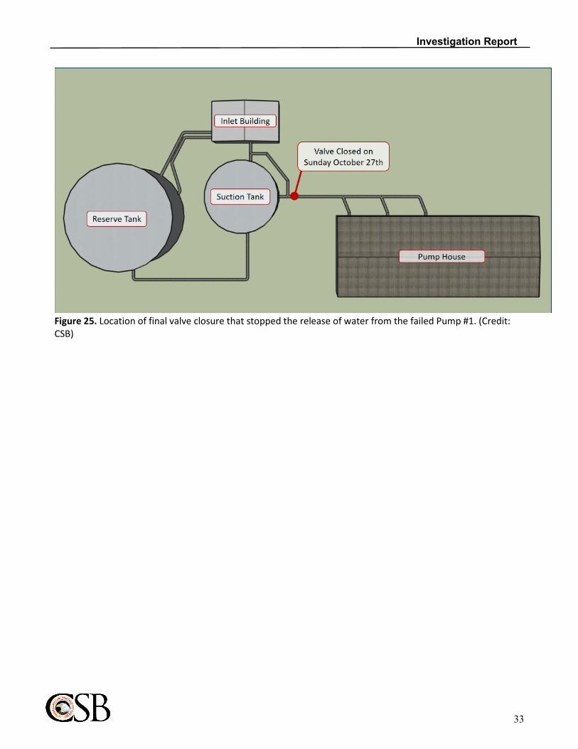
At approximately 9:00 a.m. on Sunday, October 27, 2019, the Aghorn vice president then met with Odessa Fire Rescue at the gate to the waterflood station. Several firefighters donned SCBA and walked to the waterflood station. They reported that they could still see water coming out of the pump and were measuring high H2S gas levels. To stop the water flow, the vice president directed the fire department to close the valve at the bottom of the suction tank (Figure 25). The firefighters closed the valve, and the water stopped spilling from the pump.
a At the time of the incident, pump #2 had been removed from the facility to be serviced by a third party and already had the main electric
service disconnect switch turned off.
33
Investigation Report
Figure 25. Location of final valve closure that stopped the release of water from the failed Pump #1. (Credit: CSB)

34
Investigation Report
3 Incident Analysis The CSB determined that weather was not a significant factor in the outcome of this incident. In addition, due to the limitations of the available evidence, the CSB was unable to determine whether the pump failure and loss of containment of the produced water (1) occurred before Pumper A arrived at the facility, or (2) occurred when the pump energized while Pumper A was closing valves to isolate the pump. Also due to the limitations of the available evidence, the CSB was unable to confirm whether the pump house exhaust fans were operational at the time of the incident.
This section discusses the following safety issues the CSB identified in its investigation:
• Nonuse of Personal H2S Detector
• Nonperformance of Lockout / Tagout
• Confinement of H2S Inside Pump House
• Lack of Safety Management Program
• Nonfunctioning H2S Detection and Alarm System
• Deficient Site Security
3.1 Nonuse of Personal H2S Detector
The CSB found that Pumper A was not wearing his personal H2S detector when he was working in the pump house. After the incident, the detector was found in his work truck. It was in an alarm state, meaning it had detected dangerous levels of H2S.
The CSB concludes that:
• Since the waterflood station equipment contained deadly H2S, Aghorn should have trained its employees, which should have led to Pumper A being aware, that an equipment malfunction could indicate an H2S release;
• Pumper A was not wearing his personal H2S detection device upon entering the facility, and there is no evidence that Aghorn management required the use of these devices;
• Regardless of when the pump failed, had Pumper A been wearing his personal H2S detection device, he could have been alerted of the H2S danger and potentially been able to escape prior to succumbing to the toxic gas; and
• All Aghorn facilities where the potential exists to expose workers or non-employees to H2S concentrations at or above 10 ppm would benefit from the mandatory use of personal H2S detection devices as an integral part of every employee or visitor personal protective equipment (PPE) kit prior to entering the vicinity of the facility.

35
Investigation Report
The CSB recommends to Aghorn that for all waterflood stations where the potential exists to expose workers or non-employees to H2S concentrations at or above 10 ppm, Aghorn mandate the use of personal H2S detection devices as an integral part of every employee or visitor personal protective equipment (PPE) kit prior to entering the vicinity of the facility. Ensure detector use is in accordance with manufacturer specifications.
3.2 Nonperformance of Lockout / Tagout
Pumper A did not perform Lockout / Tagout to deenergize Pump #1 before performing work on it. He closed Pump #1’s discharge valve and partially closed Pump #1’s suction valve while the pump was still configured to be automatically operated by the PLC. The PLC’s automatic activation of Pump #1 allowed water containing H2S to release from the pump.
OSHA 29 CFR 1910.147 – The Control of Hazardous Energy (Lockout / Tagout) covers “practices and procedures necessary to disable machinery or equipment, thereby preventing the release of hazardous energy while employees perform servicing and maintenance activities” [12]. In this standard, employers are required to develop, document, implement, and enforce energy control procedures. Aghorn did not have a written Lockout / Tagout program at the time of the incident, and the nonperformance of Lockout / Tagout contributed to both fatal injuries during the incident. Aghorn did not provide the CSB with sufficient records for CSB investigators to determine to what extent Pumper A was trained on the verbal Lockout / Tagout practice.
The CSB concludes that:
• Aghorn did not comply with OSHA regulation 29 CFR 1910.147 – The Control of Hazardous Energy (Lockout / Tagout) to ensure equipment was isolated from energy sources prior to performing work on it;
• Aghorn’s lack of a formalized and comprehensive Lockout / Tagout program contributed to Pumper A’s failure to deenergize Pump #1 before performing work on it;
• Had Pumper A locked out and tagged out Pump #1 before performing work on it, the significant H2S release and fatal outcome of the incident may not have occurred; and
• All Aghorn facilities should have a formalized and comprehensive Lockout / Tagout program, to include policies, procedures, and training, to protect workers from energized equipment hazards, such as exposure to H2S.
The CSB recommends to Aghorn for all Aghorn facilities, develop a site-specific, formalized and comprehensive Lockout / Tagout program, to include policies, procedures, and training, to protect workers from energized equipment hazards, such as exposure to H2S. Ensure the program meets the requirements outlined in 29 CFR 1910.147 and includes energy control procedures, training, and periodic inspections.
3.3 Confinement of H2S Inside Pump House
The pump house was ventilated by the two bay doors on the east side of the pump house (Figure 26). On the night of the incident, these doors were approximately 60% open. These open bay doors and any other available ventilation methods, however, did not adequately ventilate toxic H2S gas from the building during the incident, contributing to the high H2S levels to which Pumper A and his spouse were exposed. Due to the limitations of

36
Investigation Report
the available evidence, the CSB was unable to confirm whether the pump house exhaust fans were operational at the time of the incident.
Figure 26. Photos showing bay door positions. (Credit: CSB)
In 2014 there was an incident at a DuPont chemical facility in La Porte, Texas, in which a toxic gas, methyl mercaptan, was released inside a production building. The release resulted in the deaths of four employees. The CSB’s investigation of that incident found that the building trapped and concentrated leaks inside, increased risk to workers, and “exposed personnel to highly toxic chemical exposure and asphyxiation hazards” [13]. In other areas of the plant, the company had moved other processes that used highly toxic chemicals out of an enclosed building into an open structure.
The CSB concludes that:
• Aghorn’s pump system could operate outdoors, and at the time of the incident, confinement and inadequate ventilation allowed H2S to accumulate to deadly levels inside the pump house;
• Aghorn did not have sufficient fixtures or facilities to ventilate the pump house, and there is no evidence of Aghorn’s assessment of the facility design to ensure proper ventilation; and
• All facilities where the potential exists to expose workers to H2S concentrations at or above 10 ppm would benefit from a comprehensive analysis of the facility design vis-à-vis ventilation and mitigation systems to ensure that workers are not exposed to toxic gas levels.
The CSB recommends to Aghorn for all waterflood stations where the potential exists to expose workers to H2S concentrations at or above 10 ppm, commission an independent and comprehensive analysis of each facility design vis-à-vis ventilation and mitigation systems to ensure that, in the event of an accidental release, workers are protected from exposure to toxic gas levels.

37
Investigation Report
3.4 Lack of Safety Management Program
The CSB requested from Aghorn “all written policies and procedures used by Aghorn Operating.” Aghorn’s response included: 1) a cell phone use policy, 2) an alarm call out procedure, 3) a Lockout / Tagout policy and procedure that was created post-incident, and 4) a pamphlet on H2S hazards. Aghorn had no additional formal company safety or operational policies or procedures.
Section 3.2 of this report describes that Aghorn did not comply with OSHA regulation 29 CFR 1910.147 – The Control of Hazardous Energy (Lockout / Tagout) to ensure equipment was isolated from energy sources prior to performing work on it. In addition, Aghorn also did not comply 29 CFR 1910.1000 – Air Contaminants, which requires employers to implement administrative or engineering controls to minimize or eliminate the risk of employees being exposed to air contaminants. Aghorn failed on many levels to comply with this requirement, from the assessment of the building design and ventilation to maintenance of critical detection and alarm infrastructure, to operational procedures to assess, prioritize, and mitigate risks of exposure to H2S. The CSB concludes that Aghorn did not adhere to the OSHA regulatory requirement 29 CFR 1910.1000 – Air Contaminants to implement administrative or engineering controls to minimize or eliminate the risk of employees being exposed to air contaminants. Aghorn was cited by OSHA after the incident for not implementing controls to reduce exposure to H2S [14]. The failure to adhere to regulatory requirements and the lack of written policies and procedures indicates that Aghorn did not have a robust safety management program to protect its workers.
The CSB concludes that:
• Aghorn did not employ sound safety management principles in addressing the risks associated with H2S at the Foster D waterflood station facility;
• Aghorn lacked operational, training, testing, and maintenance procedures and records;
• Comprehensive safety management practices include risk identification, assessment, mitigation and monitoring of design, procedures, maintenance and training, and are an essential element of protecting workers and non-employees from toxic gases at chemical plants; and
• All facilities where the potential exists to expose workers or non-employees to H2S concentrations at or above 10 ppm should be governed by a safety management program that includes a focus on protecting workers and non-employees from toxic H2S gas.
The CSB recommends to Aghorn for all waterflood stations where the potential exists to expose workers or non-employees to H2S concentrations at or above 10 ppm, develop and demonstrate the use of a safety management program that includes a focus on protecting workers and non-employees from H2S. This program should include risk identification, assessment, mitigation, and monitoring of design, procedures, maintenance and training related to H2S. This program must be in compliance with 29 CFR 1910.1000 – Air Contaminants and 29 CFR 1910.147 – The Control of Hazardous Energy (Lockout / Tagout).
3.4.1 Opportunity for Improved Hazard Communication by Regulators OSHA requires employers to develop, document, implement, and enforce energy control procedures in 29 CFR 1910.147 – The Control of Hazardous Energy (Lockout / Tagout) and requires employers to implement administrative or engineering controls to minimize or eliminate the risk of employees being exposed to air contaminants in 29 CFR 1910.1000 – Air Contaminants. Aghorn not adhering to these regulatory requirements

38
Investigation Report
contributed to the incident. The CSB concludes that improved communication of the hazards that contributed to this incident, as well as the regulatory requirements to control those hazards, could help prevent future similar incidents.
The CSB recommends to OSHA to issue a safety information product (such as a safety bulletin or safety alert) that addresses the requirements for protecting workers from hazardous air contaminants and from hazardous energy.
The CSB also recommends to the Railroad Commission of Texas to develop and send a Notice to Operators to all oil and gas operators that fall under the jurisdiction of the Railroad Commission of Texas that describes the safety issues described in this report, including:
1. Nonuse of Personal H2S Detector
2. Nonperformance of Lockout / Tagout
3. Confinement of H2S Inside Pump House
4. Lack of Safety Management Program
5. Nonfunctioning H2S Detection and Alarm System
6. Deficient Site Security
3.5 Nonfunctioning H2S Detection and Alarm System
3.5.1 Aghorn H2S Detection and Alarm System The CSB tested the H2S detection system and found that none of the working detectors communicated with the alarm’s control panel located in the control room. Some of the facility’s detectors were set to a testing mode, which prevented them from sending an alarm signal. Other sensors that were correctly set up were unable to send a signal to the control room. Therefore, the control panel did not trigger an H2S alarm on the night of the incident.
The CSB also requested from Aghorn all maintenance and calibration records for the H2S detection and alarm system. Aghorn responded to the CSB stating that it did not locate any responsive documents.
The CSB concludes that:
• Aghorn did not maintain or properly configure its Foster D waterflood station facility H2S detection and alarm system;
• Without the alarm panel receiving any signals from the detectors, neither the beacon light nor the phone system alerted Pumper A to the dangerous atmosphere;
• Had Aghorn properly maintained and configured the H2S detection and alarm system, and if produced water and H2S released prior to his arrival, Pumper A would have been notified of the presence of toxic levels of H2S in and around the pump house; and

39
Investigation Report
• At all facilities where the potential exists to expose workers to H2S concentrations at or above 10 ppm, the H2S detection and alarm system should be properly maintained and configured, and companies should have a program and process that addresses installation, calibration, inspection, maintenance, training, and routine operations.
The CSB recommends to Aghorn for all waterflood stations where the potential exists to expose workers to H2S concentrations at or above 10 ppm, ensure the H2S detection and alarm systems are properly maintained and configured, and develop site-specific detection and alarm programs and associated procedures based on manufacturer specifications, current codes, standards, and industry good practice guidance. The program must address installation, calibration, inspection, maintenance, training and routine operations.
3.5.2 Improved System Design
3.5.2.1 Alternative Design A fully functional alarm system should alert employees arriving to the facility of any potential H2S danger. The visual component of the Aghorn system relied on a light to turn on when sensors detected an H2S release. However, a weakness of this design is that a component failure, such as a burned-out lightbulb, could falsely indicate that a structure is safe to enter during a toxic gas release. Other designs avoid this problem; for example, CSB’s DuPont Interim Recommendations Report describes a structure which uses a detection system that does not rely on a light to turn on. Detection systems inside DuPont’s structure continuously monitor the atmosphere. If a leak occurs and the atmosphere inside is unsafe for people, an alarm sounds and a green light outside the door, which is normally continuously lit, turns off to indicate it is not safe to enter (Figure 27) [13]. A sign on the door states, “Do not enter if green light is off.” When the light is off, employees must assume the environment inside the building is not safe.
Facilities that are not continuously occupied, such as the Foster D waterflood station, can implement a system similar to this DuPont design. If employees arrive at the facility and the light is off, they would be required to
Figure 27. An alternative detection system design. (Credit: CSB)
40
Investigation Report
treat entering the structure as if the hazard, such as H2S, exists at dangerous levels on the other side of the door. Installation of this type of design would significantly increase safety at facilities where equipment processes toxic fluids.
3.5.2.2 Multiple Layers of Alerts Field alarm systems employing both visual and audible mediums can more effectively alert site personnel of a hazardous condition. The CSB concludes that:
• Aghorn’s H2S detection and field alarm system was not designed with multiple layers of alerts, leading to the opportunity for a single-point failure. Had the H2S release occurred after Pumper A arrived on-scene, the one alerting device remaining would only have been evidenced from outside the pump house;
• Regardless of when produced water and H2S released, had there been multiple layers of alerts in the H2S detection and alarm system design at the facility, such as through both visual and audible alerts both internal and external to the pump house, Pumper A would have been warned of pending danger;
• Even if the field H2S alert system had been tested and operational, as designed, it was highly unlikely to have deterred the spouse from entering the facility or provided her with warning of released hazardous chemicals that might threaten her life or those of her children;
• Audible alarms provide additional warning of toxic gas hazards; and
• All facilities where the potential exists to expose workers or non-employees within the perimeter of the facility to H2S concentrations at or above 10 ppm would benefit from H2S detection and alarm system designs that employ multiple layers of alerts unique to H2S, such as with the use of both audible and visual mediums, so that workers and non-employees in all locations would be alerted to a significant release.
The CSB recommends to Aghorn for all waterflood stations where the potential exists to expose workers or non-employees within the perimeter of the facility to H2S concentrations at or above 10 ppm, ensure that the H2S detection and alarm system designs employ multiple layers of alerts unique to H2S, such as with the use of both audible and visual mediums, so that workers and non-employees within the perimeter of the facility would be alerted to a significant release. The system design must meet manufacturer specifications, current codes, standards, and industry good practice guidance.
3.6 Deficient Site Security
When an Aghorn employee is working at the facility, the access gates are normally left unlocked. Aghorn stated that the gates were normally locked after employees left the facility. Both access gates were open and unlocked on the night of the incident while Pumper A was at the facility. Because the gates were open, the spouse would have been especially unlikely to see the H2S warning signs because they were corroded, and she arrived during night conditions. The last line of defense would have been securing the perimeter. The unlocked gates allowed Pumper A’s spouse to drive up to the waterflood station and enter the pump house, where she was exposed to toxic H2S gas.
Several industry standards issue guidance and requirements for site security at petroleum and petrochemical facilities, two of which include ANSI/API Standard 780—Security Risk Assessment Methodology for the

41
Investigation Report
Petroleum and Petrochemical Industries and API RP 781—Facility Security Plan Methodology for the Oil and Natural Gas Industries. Relevant content of these two standards is below.
ANSI/API Standard 780—Security Risk Assessment Methodology for the Petroleum and Petrochemical Industries
The premise of this Standard is that security risks should be managed in a risk-based, performance-oriented management process to ensure the security of assets and the protection of the public, the environment, workers, and the continuity of the business. A [security risk assessment] is a management tool that should be used to assist in accomplishing this ask and to help the owner/operator in making decisions on the need for and value of security enhancements. […]
The user defines a certain number of credible scenarios to produce a representative risk estimate. Then the user shall consider the following five basic strategies when conducting the analysis and assessing the adequacy of countermeasures.
1) Deter—A countermeasures strategy that is intended to prevent or discourage the occurrence of a breach of security by means of fear or doubt. Physical security elements such as warning signs, lights, uniformed guards, cameras, and fences are examples of visible countermeasures that provide deterrence in addition to their primary security purpose.
2) Detect—A countermeasures strategy that is intended to identify a threat attempting to commit a security event in order to provide real-time observation as well as post-incident analysis of the activities and identity of the threat. Examples are patrols, alarm systems, and closed circuit television (CCTV) cameras.
3) Delay—A countermeasures strategy that is intended to provide various barriers to slow the progress of a threat in penetrating a site to prevent an attack or theft, or in leaving a restricted area to assist in interdiction. Examples include access control checkpoints, door locks, and bars on windows.
4) Respond—The act of reacting to detected malevolent activity. This may include activities to interdict, prevent damage or future loss, or control the incident. Protective forces, response plans, and emergency shutdown systems are typical examples.
5) Recover—Means such as redundance or resiliency to mitigate the effects of the security event and to continue or return operations expeditiously with minimum collateral damages, downtime, and other impacts. Backup servers, spare long-lead equipment, or extra capacity are examples of recovery capability [16, pp. 10-11].

42
Investigation Report
API RP 781—Facility Security Plan Methodology for the Oil and Natural Gas Industries
The facility shall employ multiple security systems working together to form a layered approach to security that may include countermeasures, such as perimeter fencing, designated restricted areas, barriers, closed-circuit television (CCTV), intrusion detection sensors, and controlled access points, The above list is not all inclusive.
[…]
Fencing, clear zones, and visual observations are the first layers of defense for the facility by marking the boundaries of the facility, providing a psychological deterrent discouraging unauthorized persons from entering the facility, and providing a temporary delay for those that try.
[…]
Properly designed gates, in conjunction with the perimeter fence, channel both vehicles and pedestrians to a limited number of access control points where their identity can be verified before they are granted access to the facility. All gates should be secured or monitored utilizing manpower or CCTV. The facility shall limit the number of gates to the number necessary to safely operate the facility. Any unnecessary gates should be removed and replaced with the perimeter fence [17, pp. 20-21]. (emphasis added)
The CSB concludes that:
• Pumper A’s spouse likely did not see the H2S warning signs because they were corroded, and she arrived during night conditions. If she did see the H2S warning signs, she may not have known that she could have been in danger;
• Aghorn’s site security did not meet industry guidance and standards, to include ANSI/API Standard 780 – Security Risk Assessment Methodology for the Petroleum and Petrochemical Industries, and API RP 781 – Facility Security Plan Methodology for the Oil and Natural Gas Industries;
• Had Aghorn designed the facility according to these guidelines, the gates would have been secured, preventing Pumper A’s spouse from entering the facility; and
• All facilities where the potential exists to expose workers or non-employees to H2S concentrations at or above 10 ppm would benefit from formal, written, site-specific security programs that require employees to lock access gates upon entering and departing the facility.
The CSB recommends to Aghorn for all waterflood stations where the potential exists to expose non-employees to H2S concentrations at or above 10 ppm, develop and implement a formal, written, site-specific security program to prevent unknown and unplanned entrance of those not employed by Aghorn, starting with a requirement for employees to lock access gates upon entering and departing the facility.

43
Investigation Report
4 Conclusions 4.1 Findings
1. Weather was not a significant factor in the outcome of this incident.
2. Due to the limitations of the available evidence, the CSB was unable to determine whether the pump failure and loss of containment of the produced water (1) occurred before Pumper A arrived at the facility, or (2) occurred when the pump energized while Pumper A was closing valves to isolate the pump.
3. Due to the limitations of the available evidence, the CSB was unable to confirm whether the pump house exhaust fans were operational at the time of the incident.
4. Since the waterflood station equipment contained deadly H2S, Aghorn should have trained its employees, which should have led to Pumper A being aware, that an equipment malfunction could indicate an H2S release.
5. Pumper A was not wearing his personal H2S detection device upon entering the facility, and there is no evidence that Aghorn management required the use of these devices.
6. Regardless of when the pump failed, had Pumper A been wearing his personal H2S detection device, he could have been alerted of the H2S danger and potentially been able to escape prior to succumbing to the toxic gas.
7. All Aghorn facilities where the potential exists to expose workers or non-employees to H2S concentrations at or above 10 ppm would benefit from the mandatory use of personal H2S detection devices as an integral part of every employee or visitor personal protective equipment (PPE) kit prior to entering the vicinity of the facility.
8. Aghorn did not comply with OSHA regulation 29 CFR 1910.147 – The Control of Hazardous Energy (Lockout / Tagout) to ensure equipment was isolated from energy sources prior to performing work on it.
9. Aghorn’s lack of a formalized and comprehensive Lockout / Tagout program contributed to Pumper A’s failure to deenergize Pump #1 before performing work on it.
10. Had Pumper A locked out and tagged out Pump #1 before performing work on it, the significant H2S release and fatal outcome of the incident may not have occurred.
11. All Aghorn facilities should have a formalized and comprehensive Lockout / Tagout program, to include policies, procedures, and training, to protect workers from energized equipment hazards, such as exposure to H2S.
12. Aghorn’s pump system could operate outdoors, and at the time of the incident, confinement and inadequate ventilation allowed H2S to accumulate to deadly levels inside the pump house.
13. Aghorn did not have sufficient fixtures or facilities to ventilate the pump house, and there is no evidence of Aghorn’s assessment of the facility design to ensure proper ventilation.

44
Investigation Report
14. All facilities where the potential exists to expose workers to H2S concentrations at or above 10 ppm would benefit from a comprehensive analysis of the facility design vis-à-vis ventilation and mitigation systems to ensure that workers are not exposed to toxic gas levels.
15. Aghorn did not adhere to the OSHA regulatory requirement 29 CFR 1910.1000 – Air Contaminants to implement administrative or engineering controls to minimize or eliminate the risk of employees being exposed to air contaminants.
16. Aghorn did not employ sound safety management principles in addressing the risks associated with H2S at the Foster D waterflood station facility.
17. Aghorn lacked operational, training, testing, and maintenance procedures and records.
18. Comprehensive safety management practices include risk identification, assessment, mitigation and monitoring of design, procedures, maintenance and training, and are an essential element of protecting workers and non-employees from toxic gases at chemical plants.
19. All facilities where the potential exists to expose workers or non-employees to H2S concentrations at or above 10 ppm should be governed by a safety management program that includes a focus on protecting workers and non-employees from toxic H2S gas.
20. Improved communication of the hazards that contributed to this incident, as well as the regulatory requirements to control those hazards, could help prevent future similar incidents.
21. Aghorn did not maintain or properly configure its Foster D waterflood station facility H2S detection and alarm system.
22. Without the alarm panel receiving any signals from the detectors, neither the beacon light nor the phone system alerted Pumper A to the dangerous atmosphere.
23. Had Aghorn properly maintained and configured the H2S detection and alarm system, and if produced water and H2S released prior to his arrival, Pumper A would have been notified of the presence of toxic levels of H2S in and around the pump house.
24. At all facilities where the potential exists to expose workers to H2S concentrations at or above 10 ppm, the H2S detection and alarm system should be properly maintained and configured, and companies should have a program and process that addresses installation, calibration, inspection, maintenance, training, and routine operations.
25. Aghorn’s H2S detection and field alarm system was not designed with multiple layers of alerts, leading to the opportunity for a single-point failure. Had the chemical release occurred after Pumper A arrived on-scene, the one alerting device remaining would only have been evidenced from outside the pump house.
26. Regardless of when produced water and H2S released, had there been multiple layers of alerts in the H2S detection and alarm system design at the facility, such as through both visual and audible alerts both internal and external to the pump house, Pumper A would have been warned of pending danger.
27. Even if the field H2S alert system had been tested and operational, as designed, it was highly unlikely to have deterred the spouse from entering the facility or provided her with warning of released hazardous chemicals that might threaten her life or those of her children.

45
Investigation Report
28. Audible alarms provide additional warning of toxic gas hazards.
29. All facilities where the potential exists to expose workers or non-employees within the perimeter of the facility to H2S concentrations at or above 10 ppm would benefit from H2S detection and alarm system designs that employ multiple layers of alerts unique to H2S, such as with the use of both audible and visual mediums, so that workers and non-employees in all locations would be alerted to a significant release.
30. Pumper A’s spouse likely did not see the H2S warning signs because they were corroded, and she arrived during night conditions. If she did see the H2S warning signs, she may not have known that she could have been in danger.
31. Aghorn’s site security did not meet industry guidance and standards, to include ANSI/API Standard 780 – Security Risk Assessment Methodology for the Petroleum and Petrochemical Industries, and API RP 781 – Facility Security Plan Methodology for the Oil and Natural Gas Industries.
32. Had Aghorn designed the facility according to these guidelines, the gates would have been secured, preventing Pumper A’s spouse from entering the facility.
33. All facilities where the potential exists to expose workers or non-employees to H2S concentrations at or above 10 ppm would benefit from formal, written, site-specific security programs that require employees to lock access gates upon entering and departing the facility.
4.2 Probable Cause
The CSB determined that the probable cause of the incident was Aghorn’s failure to enforce operator use of personal H2S detectors when in the vicinity of equipment or facilities with the potential to release H2S, and Aghorn’s failure to develop, train on, and enforce Lockout / Tagout procedures that led to Pumper A performing work on a pump while it was still energized. Contributing to the incident was Aghorn’s facility physical and operational design, which did not allow for adequate ventilation of the toxic H2S gas inside the pump house, and Aghorn’s deficient safety management program. Likely also contributing to the incident was Aghorn’s failure to maintain and properly configure the site H2S detection and alarm system. Contributing to the severity of the incident was Aghorn’s poor site security that allowed Pumper A’s spouse to gain access to the facility.

46
Investigation Report
5 Recommendations To prevent future chemical incidents, and in the interest of driving chemical safety change to protect people and the environment, the CSB makes the following safety recommendations:
5.1 Aghorn Operating Inc.
2020-01-I-TX-R1
For all waterflood stations where the potential exists to expose workers or non-employees to H2S concentrations at or above 10 ppm, mandate the use of personal H2S detection devices as an integral part of every employee or visitor personal protective equipment (PPE) kit prior to entering the vicinity of the facility. Ensure detector use is in accordance with manufacturer specifications.
2020-01-I-TX-R2
For all Aghorn facilities, develop a site-specific, formalized and comprehensive Lockout / Tagout program, to include policies, procedures, and training, to protect workers from energized equipment hazards, such as exposure to H2S. Ensure the program meets the requirements outlined in 29 CFR 1910.147 and includes energy control procedures, training, and periodic inspections.
2020-01-I-TX-R3
For all waterflood stations where the potential exists to expose workers to H2S concentrations at or above 10 ppm, commission an independent and comprehensive analysis of each facility design vis-à-vis ventilation and mitigation systems to ensure that, in the event of an accidental release, workers are protected from exposure to toxic gas levels.
2020-01-I-TX-R4
For all waterflood stations where the potential exists to expose workers or non-employees to H2S concentrations at or above 10 ppm, develop and demonstrate the use of a safety management program that includes a focus on protecting workers and non-employees from H2S. This program should include risk identification, assessment, mitigation, and monitoring of design, procedures, maintenance and training related to H2S. This program must be in compliance with 29 CFR 1910.1000 – Air Contaminants and 29 CFR 1910.147 – The Control of Hazardous Energy (Lockout / Tagout).
2020-01-I-TX-R5
For all waterflood stations where the potential exists to expose workers to H2S concentrations at or above 10 ppm, ensure the H2S detection and alarm systems are properly maintained and configured, and develop site-specific detection and alarm programs and associated procedures based on manufacturer specifications, current codes, standards, and industry good practice guidance. The program must address installation, calibration, inspection, maintenance, training and routine operations.

47
Investigation Report
2020-01-I-TX-R6
For all waterflood stations where the potential exists to expose workers or non-employees within the perimeter of the facility to H2S concentrations at or above 10 ppm, ensure that the H2S detection and alarm system designs employ multiple layers of alerts unique to H2S, such as with the use of both audible and visual mediums, so that workers and non-employees within the perimeter of the facility would be alerted to a significant release. The system design must meet manufacturer specifications, current codes, standards, and industry good practice guidance.
2020-01-I-TX-R7
For all waterflood stations where the potential exists to expose non-employees to H2S concentrations at or above 10 ppm, develop and implement a formal, written, site-specific security program to prevent unknown and unplanned entrance of those not employed by Aghorn, starting with a requirement for employees to lock access gates upon entering and departing the facility.
5.2 Occupational Safety and Health Administration (OSHA)
2020-01-I-TX-R8
Issue a safety information product (such as a safety bulletin or safety alert) that addresses the requirements for protecting workers from hazardous air contaminants and from hazardous energy.
5.3 Railroad Commission of Texas
2020-01-I-TX-R9
Develop and send a Notice to Operators to all oil and gas operators that fall under the jurisdiction of the Railroad Commission of Texas that describes the safety issues described in this report, including:
1. Nonuse of Personal H2S Detector
2. Nonperformance of Lockout / Tagout
3. Confinement of H2S Inside Pump House
4. Lack of Safety Management Program
5. Nonfunctioning H2S Detection and Alarm System
6. Deficient Site Security

48
Investigation Report
6 Key Lessons for the Industry To prevent future chemical incidents, and in the interest of driving chemical safety change to protect people and the environment, the CSB urges companies operating facilities that handle toxic chemicals to review these key lessons:
1. Employers should take action to ensure workers always use the required safety equipment, such as personal detectors, when entering an area where there is the potential for a hazardous atmosphere. Companies should conduct regular training to reinforce this priority, and post signs to help remind employees to use the detectors. Ensure detector use is in accordance with manufacturer specifications.
2. Per OSHA 29 CFR 1910.147, facilities must have written Lockout / Tagout policies and procedures that provide instruction on isolating all possible sources of energy before employees perform work on equipment. Sources of energy may include chemical, electrical, kinetic, potential, hydraulic, or temperature. Companies also need to routinely train employees on the proper Lockout / Tagout practices in the areas in which they may work.
3. At facilities where equipment that handles toxic gas is contained within a building, the building may confine toxic gas during a release, exacerbating the hazard for workers. Companies should evaluate any structure that contains equipment handling toxic gases and determine if the building is necessary. If it is determined that the building is necessary, companies should (a) ensure the building is equipped with a functioning toxic gas detection and alarm system and (b) ensure the building is equipped with a ventilation system designed for the release of toxic gases. Both systems require regular preventive maintenance. If the building is not necessary for the operation, a safety assessment should be conducted to determine if removal of the building or relocation of the equipment processing toxic gas can safely prevent confinement of toxic gas releases.
4. Comprehensive safety management practices include risk identification, assessment, mitigation and monitoring of design, procedures, maintenance and training, and are an essential element of protecting workers and non-employees from toxic gases at chemical plants.
5. At facilities that handle toxic gases, gas detection and alarm systems must be adequately designed, maintained and tested. Test frequency must be established to ensure the system provides adequate warning of the presence of toxic chemicals. Alarms should clearly alert to the hazard through visual and audible indications. Visual indications always need to be visible during any time of day. Signs should also be posted, alerting that the facility handles toxic gas. Facilities should design toxic gas detection and alarm systems such that a component failure—such as a burned-out light bulb—does not lead to the system providing a false indication that an area is safe to enter.
6. Industrial facilities should ensure effective site security is in place to prevent non-employees from accessing hazardous areas, for example through usage of fencing, signage, closed and locked gates, security cameras, and security guards. Industry standards and recommended practices, including ANSI/API Standard 780—Security Risk Assessment Methodology for the Petroleum and Petrochemical Industries and API RP 781—Facility Security Plan Methodology for the Oil and Natural Gas Industries, provide site security requirements and best practices.

49
Investigation Report
7 References
[1] V. S. Vishnyakov, B. Salmanov and E. Ahmad Zeynalov, "Oil recovery stages and methods," in Primer on Enhanced Oil Recovery, Gulf Professional Publishing, 2020, pp. 53 - 56.
[2] Office of Fossil Energy, "Enhanced Oil Recovery," [Online]. Available: https://www.energy.gov/fe/science-innovation/oil-gas-research/enhanced-oil-recovery. [Accessed 04 2020].
[3] P. Chhabra and V. Shankar, Coulson and Richardson's Chemical Engineering, Volume 1A, Fluid Flow: Fundamentals and Applications 7th, Cambridge, MA: Elsevier, 2018.
[4] Occupational Safety and Health Administration, "OSHA Fact Sheet - Hydrogen Sulfide," [Online]. Available: https://www.osha.gov/OshDoc/data_Hurricane_Facts/hydrogen_sulfide_fact.pdf. [Accessed April 2020].
[5] National Institute for Occupational Safety and Health, "Table of IDLH Values - Hyrdogen Sulfide," May 1994. [Online]. Available: https://www.cdc.gov/niosh/idlh/7783064.HTML. [Accessed 30 January 2020].
[6] U.S. Department of Labor, Occupational Safety and Health Administration, "Safety and Health Topics: Hydrogen Sulfide," [Online]. Available: https://www.osha.gov/SLTC/hydrogensulfide/hazards.html. [Accessed 30 January 2020].
[7] Weather Underground, "Odessa, TX Weather History," 26 October 2019. [Online]. Available: https://www.wunderground.com/history/daily/us/tx/odessa/KODO/date/2019-10-26.
[8] L. Sumi, "Shale Gas: Focus on the Marcellus Shale," May 2008. [Online]. Available: https://www.nrc.gov/docs/ML1430/ML14308A229.pdf.
[9] D. Xia and Z. He, "Hydrogen Sulfide (H2S) in the Permian Basin," Adapted from oral presentation given at AAPG 2017 Annual Convention and Exhibition, Houton, Texas, 12 June 2017. [Online]. Available: http://www.searchanddiscovery.com/documents/2017/10950xia/ndx_xia.pdf. [Accessed 18 March 2021].
[10] US. Energy Information Administration, "Drilling Productivity Report for Key Tight Oil and Shale Gas Regions," March 2021. [Online]. Available: https://www.eia.gov/petroleum/drilling/pdf/dpr-full.pdf. [Accessed 18 March 2021].
[11] R. McCurdy, "Underground Injection Wells for Produced Water Disposal," Chesapeake Energy Corporation, [Online]. Available: https://www.epa.gov/sites/production/files/documents/21_McCurdy_-_UIC_Disposal_508.pdf. [Accessed 18 March 2021].

50
Investigation Report
[12] Occupational Safety and Health Administration, "OSHA Fact Sheet," 2002. [Online]. Available: https://www.osha.gov/OshDoc/data_General_Facts/factsheet-lockout-tagout.pdf. [Accessed 10 September 2020].
[13] U.S. Chemical Safety Board, "DuPont La Porte Interim Recommendations, Texas Chemical Facility Toxic Chemical Release," 2015. [Online]. Available: https://www.csb.gov/assets/1/20/dupont_la_porte_interim_recommendations_2015-09-30_final1.pdf?15526. [Accessed June 2020].
[14] Occupational Safety and Health Administration, "Inspection Detail," [Online]. Available: https://www.osha.gov/pls/imis/establishment.inspection_detail?id=1440890.015. [Accessed 21 January 2021].
[15] U.S. Department of Labor Occupational Safety and Health Administration (OSHA), "OSHA Regional Instruction, Directive Number CPL 2 02-00-013A," 01 October 2019. [Online]. Available: https://www.osha.gov/sites/default/files/enforcement/directives/CPL_2_02-00-013A.pdf. [Accessed 13 April 2021].
[16] American Petroleum Institute, ANSI/API Standard 780 - Security Risk Assessment Methodology for the Petroleum and Petrochemical Industries, 1st ed., 2013.
[17] American Petroleum Institute, API RP 781 - Facility Security Plan Methodology for the Oil and Natural Gas Industries, 1st ed., 2016.
[18] I. Sutton, Process Risk and Reliability Management 2nd ed., Oxford, UK: Elsevier, 2015.
[19] Schlumberger, "Tank Battery," [Online]. Available: https://www.glossary.oilfield.slb.com/en/Terms/t/tank_battery.aspx. [Accessed 27 August 2020].
[20] Shale XP, "Company Directory - Aghorn Operating, Inc.," [Online]. Available: https://www.shalexp.com/aghorn-operating-inc. [Accessed 20 01 2020].

51
Investigation Report
Appendix A—Causal Analysis (AcciMap)
52
Investigation Report
U.S. Chemical Safety
and Hazard Investigation Board
Members of the U.S. Chemical Safety and Hazard Investigation Board:
Katherine A. Lemos, PhD Chairman and CEO