investigation report volume 2 - csb · investigation report volume 2 . e. xplosion and . f. ......
TRANSCRIPT
U.S. CHEMICAL SAFETY AND HAZARD INVESTIGATION BOARD
INVESTIGATION REPORT VOLUME 2
EXPLOSION AND FIRE AT THE MACONDO WELL (11 Fatalities, 17 Injured, and Serious Environmental Damage)
DEEPWATER HORIZON RIG
MISSISSIPPI CANYON BLOCK #252, GULF OF MEXICO
KEY ISSUES IN VOLUME 2 APRIL 20, 2010
• BOP TECHNICAL FAILURE ANALYSIS • BARRIER MANAGEMENT AT MACONDO • SAFETY CRITICAL ELEMENTS
REPORT NO. 2010-10-I-OS 6/5/2014

Macondo Investigation Report Volume 2 June 5, 2014
[This page left intentionally blank.]
2

Macondo Investigation Report Volume 2 June 5, 2014
Volume 2
Technical findings on the Deepwater Horizon blowout preventer (BOP) with an emphasis on the effective management of safety critical elements
3

Macondo Investigation Report Volume 2 June 5, 2014
[This page left intentionally blank.]
4
Macondo Investigation Report Volume 2 June 5, 2014
Contents VOLUME 2 .................................................................................................................................................. 3
ACRONYMS AND ABBREVIATIONS ................................................................................................... 10
1.1 Volume 2 Synopsis ........................................................................................................................ 13
1.2 Key Findings .................................................................................................................................. 14
2.0 CONTROLLING FORMATION PRESSURES WITH THE DEEPWATER HORIZON BLOWOUT PREVENTER ........................................................................................................... 17
2.1 BOP Sealing Elements ................................................................................................................... 19
2.2 The BOP as a Physical Barrier ....................................................................................................... 21
2.3 Functioning the Deepwater Horizon BOP ..................................................................................... 23
2.3.1 BOP Control System ......................................................................................................... 23
2.3.1.1 Functioning Solenoid Operated Valves ......................................................... 25
2.3.2 BOP: Closing the Blind Shear Ram .................................................................................. 27
2.3.3 Initiating the AMF/Deadman Sequence ............................................................................ 27
2.4 Condition of the Well on April 20, 2010—Data Used to Recreate the Incident Events ................ 28
2.5 The Macondo Well Kicks—Incident Analysis of Well Control Response .................................... 28
3.0 THE BLOWOUT PREVENTER – FAILURE OF A BARRIER .................................................. 31
3.1 Correlating Physical Evidence from Macondo with the Events of April 20, 2010 ........................ 32
3.2 Failure Analysis of the Deepwater Horizon BOP .......................................................................... 34
3.2.1.1 Blue Pod: Disconnected Wires and the Drained Battery ............................... 36
3.2.1.2 Yellow Pod: Miswired High-Pressure Shear Closes Solenoid ...................... 37
3.2.1.3 Successful AMF/Deadman Tests on the Yellow Pod .................................... 38
3.2.1.4 Independent CSB Exemplar Solenoid Testing .............................................. 38
3.2.2 The AMF/deadman Successfully Fires on April 20, 2010 ................................................ 39
3.2.3 The AMF/deadman Fails to Seal the Well: Buckled Drillpipe ......................................... 43
3.3 Conclusion ..................................................................................................................................... 45
4.0 ESTABLISHING AND MAINTAINING EFFECTIVE BARRIERS .......................................... 47
4.1 Defining the Role of a Barrier: Major Accident Events ................................................................ 47
4.2 Barriers to Prevent or Mitigate MAEs ........................................................................................... 49
4.2.1 Visualizing Barriers using a Bowtie Diagram .................................................................. 52
4.2.2 Determining the Type and Number of Barriers to Reduce Risk ....................................... 55
5

Macondo Investigation Report Volume 2 June 5, 2014
4.2.3 Maintaining Effective Barriers ......................................................................................... 57
4.2.3.1 Barriers as Safety Critical Elements (SCEs) ................................................. 58
4.3 Conclusion ..................................................................................................................................... 61
5.0 DEEPWATER HORIZON BOP NOT TREATED AS A SAFETY CRITICAL ELEMENT ...... 62
5.1 Identification of a SCE................................................................................................................... 64
5.1.1 BOP Component Failure Identified in DWH Hazard Analysis ........................................ 64
5.1.2 DWH Hazard Analysis Did Not Address BOP Design Capabilities ................................ 65
5.2 Defining Performance Requirements of a SCE ............................................................................. 66
5.2.1 Drillpipe Exceeded Shearing Capabilities of DWH Blowout Preventer .......................... 66
5.2.2 Prescribing Minimum Reliability Requirements of a BOP .............................................. 68
5.3 Performance Assurance of an SCE ................................................................................................ 70
5.3.1 No Assurance Activities for the Critical AMF/Deadman Solenoid Valve ....................... 71
5.3.2 Current Deadman System Function Tests Are Inadequate ............................................... 72
5.3.3 Assurance Activities of Human Actions ........................................................................... 76
5.4 Gap Closure ................................................................................................................................... 77
5.5 Verification Activities—The Independent Competent Person ...................................................... 78
5.6 Conclusion ..................................................................................................................................... 79
6.0 ANALYSIS OF RECOMMENDED PRACTICES AND REGULATIONS REGARDING THE BOP AND OTHER SAFETY CRITICAL DEVICES .................................................................. 81
6.1 Lifecycle of SCEs under BSEE ..................................................................................................... 82
6.1.1 Hazard Analysis not Focused on Targeted Risk Reduction of Major Accident Events ... 82
6.1.1.1 Lack of Targeted Risk Reduction Requirements: Parallel Findings between the CSB Investigations ...................................................................................................... 84
6.1.2 Lack of Defined Performance Standards for all SCEs ...................................................... 85
6.1.3 Performance Assurance and Verification Needed for all SCEs ........................................ 86
6.1.4 Gap Closure Important for Continuous Improvement of SCE Effectiveness ................... 87
6.2 Regulatory Responses Post-Macondo: Prescriptive Change versus Continuous Improvement .... 88
6.2.1 BOP Shearing Capability—An Illustrative Example of Diverse Regulatory Responses . 89
6.2.2 Proposed Regulatory Changes Suggest US Recognition of the Importance of Lifecycle Management of Safety Critical Equipment ......................................................................................... 92
7.0 VOLUME 2 CONCLUSIONS: TECHNICAL SAFETY FAILURES REVEAL BROADER REGULATORY GAPS ................................................................................................................. 93
6

Macondo Investigation Report Volume 2 June 5, 2014
8.0 RECOMMENDATIONS ............................................................................................................... 95
APPENDIX 2-A: DEEPWATER HORIZON BLOWOUT PREVENTER FAILURE ANALYSIS ......... 98
APPENDIX 2-B: DEEPWATER HORIZON RBS 8D BOP MUX CONTROL SYSTEM REPORT ...... 99
APPENDIX 2-C: SCENARIOS WHEN TWO BSRS WOULD NOT BE OPTIMAL ............................ 100
REFERENCES ......................................................................................................................................... 101
7

Macondo Investigation Report Volume 2 June 5, 2014
Figures and Tables
Figures Figure 2-1. The DWH BOP stack ............................................................................................................... 18
Figure 2-2. An annular preventer can seal the annular space around a drillpipe or an open hole. Pistons press up on the rubber component which pushes it inward to seal around the pipe or open hole. ......................................................................................................................................... 19
Figure 2-3. A pipe ram can seal the annular space around a drillpipe, but not an open hole without drillpipe present. ...................................................................................................................... 20
Figure 2-4.Control panel (left) and partial closeup of control panel on the Deepwater Horizon found in the driller’s cabin and on the bridge of the rig. These controls are used to activate the BOP. ...... 23
Figure 2-5. Pressing a pushbutton on a BOP control panel sent an electronic signal through the MUX cable down to the yellow and blue BOP control pods located in the LMRP. Accumulators on the BOP stack supplied hydraulic power to the control pods during emergencies. ................ 24
Figure 2-6. The top image depicts a solenoid with no current running through it. The plunger is down, and no fluid can flow through the solenoid. When actuated, current running through the solenoid produces a magnetic field which creates a force that pulls the plunger up, allowing fluid to flow. ......................................................................................................................................... 25
Figure 2-7. Simplified schematic of the control pod battery arrangement. ................................................. 26
Figure 2-8. Key operation events after reservoir flow began. ..................................................................... 29
Figure 3-1. (Left) Photograph of Y103 wire arrangement from Phase II testing with pins 1 and 4 connected to white wires and 2 and 3 connected to black wires. (Right) Schematic of correct arrangement of wires, with pins 1 and 3 connected to white wires and 2 and 4 connected to black wires. .............................................................................................................................. 37
Figure 3-2. Miswiring in the blue pod caused the critical 27-volt battery to drain, rendering the pod inoperable during the incident. A drained 9-volt battery in the yellow pod left one of the coils in the miswired Y103 solenoid valve inoperable, allowing the other coil to activate unopposed and initiate closure of the blind shear ram. ........................................................... 40
Figure 3-3. The events that led to the likely partial closure of the BSR after the emergency AMF/deadman system activated on April 20. .................................................................................................. 42
Figure 3-4. The Deepwater Horizon BOP was designed to shear centered drillpipe (left) in the BSR and then seal the well. During the Phase I examination of the BOP, the drillpipe was found off-center (right), causing the BSR to close only partially, leaving the well unsealed. ................ 43
Figure 3-5: Theoretically straight pipe with equal inside and outside pressure (left); real pipe with a curve imperfection with equal internal and external pressure (center); pipe buckling as a result of increased internal pressure (right). The black wedges show the relative change in length and area of the two sides of the pipe. ............................................................................................. 45
8

Macondo Investigation Report Volume 2 June 5, 2014
Figure 4-1. Hierarchy of Controls. .............................................................................................................. 51
Figure 4-2. Bowtie diagram depicting the relationships between hazards, barriers, and the major accident events they are intended to prevent. ........................................................................................ 53
Figure 4-3. Bowtie diagram showing potential decay mechanisms of the technical barriers intended to prevent a fault during temporary abandonment activities. ...................................................... 54
Figure 5-1. Simplified representation of the management system for the lifecycle of a safety critical element .................................................................................................................................... 63
Figure 5-2. Simplified schematic of the Cameron FAT procedure to test the AMF/deadman. .................. 75
Tables Table 2-1. Various components of a BOP and their uses, (See Appendix 2-A for model numbers and
capabilities of the DWH BOP elements) .................................................................................. 21
Table 3-1. In addition to the three phases of DWH BOP testing from May 2010 to April 2011, the CSB completed independent exemplar solenoid valve testing in September 2012. .......................... 35
Table 4-1. Excerpts from offshore regulations from the UK, Norway, and Australia that specifically require Major Accident Events be addressed; they are juxtaposed with US regulations that promote safety and environmental protection, but without a focus on MAEs. ......................... 49
Table 4-2. Recreated excerpts of Transocean's Risk Assessment for the DWH ......................................... 50
Table 5-1. Recreated excerpt of Transocean's MAHRA for the Deepwater Horizon ................................. 65
Table 5-2. Summary of emails sent between Transocean personnel regarding BSR shearing capability. . 68
Table 6-1. Excerpts from offshore regulations from the UK, Norway, and Australia concerning a required analysis., .................................................................................................................................... 83
9
Macondo Investigation Report Volume 2 June 5, 2014
Acronyms and Abbreviations
ALARP As Low As Reasonably Practicable
AMF Automatic Mode Function
API American Petroleum Institute
BOEM Bureau of Ocean Energy Management (United States)
BOEMRE Bureau of Ocean Energy Management, Regulation, and Enforcement (United States); the US offshore safety regulator between June 18 and October 1, 2011a
BOP Blowout Preventer
BSEE Bureau of Safety and Environmental Enforcement (United States); US offshore safety regulator since October 1, 2011b
BSR Blind Shear Ram
CCPS Center for Chemical Process Safety
CSB U.S. Chemical Safety Board
CSR Casing Shear Ram
DNV Det Norske Veritas
DOI Department of Interior (United States)
DOSH Division of Occupational Safety and Health
DWH Deepwater Horizon
EDS Emergency Disconnect System
GoM Gulf of Mexico
HSE Health Safety Executive (United Kingdom)
LCM Loss Circulation Material
LMRP Lower Marine Riser Package
LOWC Loss of Well Containment
MAHRA Major Accident Hazard Risk Assessment
a Department of Interior, Order No. 3302, Change of the Name of the Minerals Management Service to the Bureau of Ocean Energy Management, Regulation, and Enforcement (June 18, 2011), http://www.doi.gov/deepwaterhorizon/loader.cfm?csModule=security/getfile&PageID=35872. Accessed February 19, 2014.
b The Reorganization of the former MMS, http://www.bsee.gov/About-BSEE/BSEE-History/Reorganization/Reorganization/. Accessed February 19, 2014.
10

Macondo Investigation Report Volume 2 June 5, 2014
MGS Mud-Gas Separator
MAE Major Accident Event
MMS Minerals Management Service (United States); US offshore safety regulator at the time of the Macondo accident until June 18, 2011a
MODU Mobile Offshore Drilling Unit
NOPSA National Offshore Petroleum Safety Authority (Australia)
NOPSEMA National Offshore Petroleum Safety and Environmental Management Authority (Australia, successor to NOPSA)
NTL Notice to Lessee
OCS Outer Continental Shelf
POSC Presidential Oil Spill Commission
PSM Process Safety Management
PETU portable electronic test unit
PLC programmable logic controllers
ppg pounds per gallon
PSA Petroleum Safety Authority (Norway)
psi pounds per square inch
SCE safety critical element
SEM subsea electronic module
SEMS Safety and Environmental Management System
SPPE Safety and Pollution Protection Equipment
UK United Kingdom
US United States
USCG United States Coast Guard
VBR Variable Bore Ram
a Department of Interior, Order No. 3302, Change of the Name of the Minerals Management Service to the Bureau of Ocean Energy Management, Regulation, and Enforcement (June 18, 2011), http://www.doi.gov/deepwaterhorizon/loader.cfm?csModule=security/getfile&PageID=35872. Accessed February 19, 2014.
11
Macondo Investigation Report Volume 2 June 5, 2014
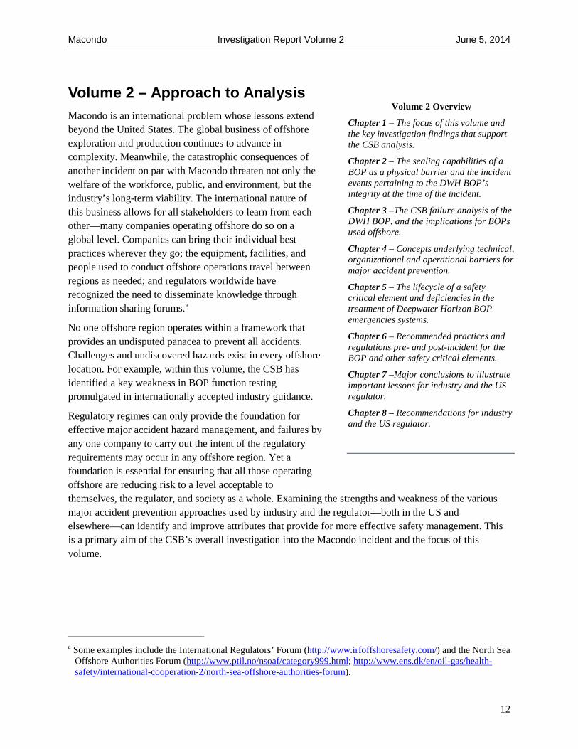
Volume 2 – Approach to Analysis Macondo is an international problem whose lessons extend beyond the United States. The global business of offshore exploration and production continues to advance in complexity. Meanwhile, the catastrophic consequences of another incident on par with Macondo threaten not only the welfare of the workforce, public, and environment, but the industry’s long-term viability. The international nature of this business allows for all stakeholders to learn from each other—many companies operating offshore do so on a global level. Companies can bring their individual best practices wherever they go; the equipment, facilities, and people used to conduct offshore operations travel between regions as needed; and regulators worldwide have recognized the need to disseminate knowledge through information sharing forums.a
No one offshore region operates within a framework that provides an undisputed panacea to prevent all accidents. Challenges and undiscovered hazards exist in every offshore location. For example, within this volume, the CSB has identified a key weakness in BOP function testing promulgated in internationally accepted industry guidance.
Regulatory regimes can only provide the foundation for effective major accident hazard management, and failures by any one company to carry out the intent of the regulatory requirements may occur in any offshore region. Yet a foundation is essential for ensuring that all those operating offshore are reducing risk to a level acceptable to themselves, the regulator, and society as a whole. Examining the strengths and weakness of the various major accident prevention approaches used by industry and the regulator—both in the US and elsewhere—can identify and improve attributes that provide for more effective safety management. This is a primary aim of the CSB’s overall investigation into the Macondo incident and the focus of this volume.
a Some examples include the International Regulators’ Forum (http://www.irfoffshoresafety.com/) and the North Sea Offshore Authorities Forum (http://www.ptil.no/nsoaf/category999.html; http://www.ens.dk/en/oil-gas/health-safety/international-cooperation-2/north-sea-offshore-authorities-forum).
Volume 2 Overview
Chapter 1 – The focus of this volume and the key investigation findings that support the CSB analysis.
Chapter 2 – The sealing capabilities of a BOP as a physical barrier and the incident events pertaining to the DWH BOP’s integrity at the time of the incident.
Chapter 3 –The CSB failure analysis of the DWH BOP, and the implications for BOPs used offshore.
Chapter 4 – Concepts underlying technical, organizational and operational barriers for major accident prevention.
Chapter 5 – The lifecycle of a safety critical element and deficiencies in the treatment of Deepwater Horizon BOP emergencies systems.
Chapter 6 – Recommended practices and regulations pre- and post-incident for the BOP and other safety critical elements.
Chapter 7 –Major conclusions to illustrate important lessons for industry and the US regulator.
Chapter 8 – Recommendations for industry and the US regulator.
12

Macondo Investigation Report Volume 2 June 5, 2014
The CSB provides its failure analysis of the BOP to spark a global reexamination of how industry is managing safety critical elementsa as well as regulatory requirements and approaches used to ensure that these management practices are effective.
1.1 Volume 2 Synopsisb
The Macondo well blowout began when the Deepwater Horizon (DWH) crew was in the final stages of temporarily abandoning the well so that a production facility could return later to extract oil and gas. BP’s temporary abandonment planc called for removing the upper portion of the drilling mud in the well before installing a surface cement plug.d The decision proved fateful because both BP and Transocean personnel on the DWH rig had misinterpreted test results e concerning the cement integrity at the bottom of the well. This error led the personnel to believe that the hydrocarbon bearing zone at the bottom of the well had been sealed when it was not. Ultimately, the blowout preventer (BOP) was the only physical barrier that could have potentially contained well fluids, but only if the crew or emergency systems could have successfully engaged it. f As the events of April 20, 2010 indicate, the BOP did not seal the well.
In analyzing the BOP failure to seal the well during the incident, Volume 2 of the CSB Macondo Incident Investigation report has five objectives:
1. To discuss key preventable hardware shortcomings affecting the reliability of the Deepwater Horizon BOP throughout the drilling activities at Macondo.
2. To account for all conditions that can cause drillpipe to buckle in a well, leaving it off-center in a BOP and potentially interfering with the BOP’s ability to seal a well. These conditions include having buckled drillpipe even when a rig crew has successfully shut in a well.
3. To explore safeguards, or barriers, that help prevent major accidents, recognizing they extend beyond physical equipment into operational and organizational elements.
4. To describe the necessity for effective identification and management of safety critical elements—technical, organizational, and operational—for preventing Macondo-like events.
a Safety critical elements are controls (hardware, people systems, or software) or tasks whose failure could cause or contribute to a major accident event or whose purpose is to prevent or limit the effects of a major accident event. (See Section 4.2.3.1)
b See Volume 1 for a basic introduction to deepwater drilling and physical barriers that can prevent a blowout. c A well may be sealed temporarily with cement or mechanical plugs to allow removal of the blowout preventer and
departure from the drilling rig. d Cement plugs are portions of cement put into a wellbore to seal it. “Surface” is typically used to refer to the most
shallow cement plug used in a well. e A number of human and organizational factors contributed to how the events unfolded leading to accepting the test
results. The CSB plans to address these factors in Volume 4 of the CSB’s Macondo Investigation Report. f Well integrity also includes the casing lining the wellbore, float valves (check valves) placed at the bottom of the
casing, and crossovers where casing of different sizes are connected to one another. Analysis in Appendix 2-A indicates the major source of hydrocarbons during the incident did not come from casing or crossover failures. While check valves can act as a physical barrier, they are unreliable and cannot be independently tested. For the analysis in this report, they are not considered a barrier because at Macondo they were either not converted or had to have failed.
13

Macondo Investigation Report Volume 2 June 5, 2014
5. To identify additional opportunities for improvement in the US offshore safety regulations that do not include clear and systematic requirements to ensure the successful performance of all safety critical elements (SCE) for reducing major accident events.
1.2 Key Findings
The redundant controls of Deepwater Horizon BOP should have increased the reliability of the BOP to seal the Macondo well during normal drilling operations and emergency situations. Two rounds of post-incident testing, including one non-public, court-ordered round and additional CSB testing, reveal new failure mechanisms in which these redundant controls can be compromised and go on undetected. From this analysis and an examination of how the BOP, was managed and regulated as a safety critical element, the following key findings demonstrate the need for further offshore safety improvements:
BOP Failure in Loss of Well Control
1. The BOP is subject to design capability limitations. A BOP can act as a barrier only if it is closed manually by the drilling crew or automatically as a result of a catastrophic event, such as a fire and explosion, which can trigger emergency backup systems. In manual operations, successful closure of the BOP depends on several human decisions that must be made before a well kick can develop into a blowout. Otherwise, well pressures and well flow can exceed the design capabilities of the BOP elements, leaving them unable to prevent or stop an active blowout (Sections 2.1 and 2.3).
2. No effective testing or monitoring was in place to verify the availability of the redundant systems in the emergency Automatic Mode Function (AMF)/deadman system.a (Sections 2.3.1, 5.3.1, and 5.4). This emergency system was programmed to activate a blind shear ram (BSR) within the BOP to shear drillpipe and seal the well (Sections 2.3.3).
The AMF/deadman uses two redundant control systems, the yellow pod and the blue pod, to initiate closure of the blind shear ram. This redundancy is intended to increase the AMF/deadman reliability, but on the day of the incident only one of the two pods was functioning:
a. The blue pod was miswired, causing a critical battery to drain and rendering the pod inoperable on the day of the incident (Section 3.2.1.1).
b. A critical solenoidb valve in the yellow pod had also been miswired. Redundant coils were designed to work in parallel to open the solenoid valve, but the miswiring caused them to oppose one another. Had both coils been successfully energized during the incident, the solenoid valve would have remained closed and unable to initiate closure of
a “Deadman” is defined by API Specification 16D 2nd Ed, Specification for Control Systems for Drilling Well Control Equipment and Control Systems for Diverter Equipment 2nd Edition: a blowout preventer safety system “designed to automatically close [and seal] the wellbore in the event of a simultaneous absence of hydraulic supply and signal transmission capacity in both subsea control pods.” Activation can occur as the result of a catastrophic event such as a fire and explosion on the rig. AMF (Automatic Mode Function) is Cameron’s version of a deadman system.
b Solenoid valve: A valve that opens and closes as the result of an electrically initiated magnetic switching device to control the flow of liquid or gas.
14

Macondo Investigation Report Volume 2 June 5, 2014
the BSR. However, a drained battery likely rendered one of these coils inoperable. This would have allowed the other coil to activate alone and initiate closure of the BSR, but buckled off-center drillpipe in the BOP prohibited the BSR from fully closing and sealing the well. (Section 3.2.1.2, 3.2.1.3, and 3.2.2).
3. Large pressure differences were established between the inside and outside of the drillpipe when well control actions by the crew sealed the well shortly after oil and gas were released onto the rig. This likely caused drillpipe in the BOP to buckle due to a phenomenon known as “effective compression”a (Section 3.2.3).
BOP Safety Management Deficiencies
4. The BOP systems responsible for shearing drillpipe in emergency situations are vulnerable to failures in rarely or inadequately tested equipment. Transocean and BP conducted routine inspection and weekly function testing of operational BOP components necessary for daily drilling operations, but these were insufficient to identify latent failures of the emergency systems that existed in the Deepwater Horizon BOP; thus, the safety critical systems responsible for shearing drillpipe in emergency situations had performance deficiencies even before the BOP was deployed to the Macondo wellhead. (Chapter 5.0).
5. The blind shear ramb in the Deepwater Horizon BOP did not meet the manufacturer’s published design shearing capabilities for the diameter of drillpipe used during all of the DWH drilling operations except on April 20; thus, for an extended time during the drilling process, the DWH BOP could not have reliably sheared the drillpipe during an emergency situation. (Section 5.2.1).
6. The miswired solenoid valve in the yellow pod and the deficient wiring in the blue pod could not have passed the manufacturer’s factory acceptance testing procedures (Sections 5.3.1and 5.3.2).
Regulatory Gaps
7. While US offshore regulations have undergone important changes since Macondo, more can be done to ensure a focus on preventing major accident events and to drive continuous safety improvement. The primary US offshore safety management regulation, Safety and Environmental Management Systems,
a. Is not risk-based nor does it have an explicit focus on major accident events (Chapter 4.0);
b. does not require demonstration by industry that process safety concepts for hazard assessment and management, such as layers of protectionc and hierarchy of controls, have been used in managing major accident hazardsa (Chapter 4.0);
a Effective compression: Pipe buckling resulting from the combined effect of 1) large pressure differences inside and outside of a drillpipe and 2) axial forces. Even in the absence of axial forces, pipe can buckle as a result of the pressure differences alone.
b Blind shear rams are a part of the BOP that can shear drillpipe and seal a wellbore. c Layers of protection are preventions, safeguard, barriers, or lines of defense that are designed to eliminate, prevent,
reduce, or mitigate a hazardous scenario.
15

Macondo Investigation Report Volume 2 June 5, 2014
c. does not require demonstration that barriers to prevent major accidents are effectively implemented to a targeted risk reduction level (Section 4.1).
d. does not require industry to identify and manage all safety critical elements and tasks through defined performance standards,b nor does it require assurance and verification activities to ensure a safety critical element is appropriate, available, and effective throughout its life cycle. (Chapter 5.0).
8. At the time of the incident, neither recommended industry practices nor US regulations required testing of the AMF/deadman system. Despite post-incident changes that call for function testing the AMF/deadman, deficiencies identified during the failure analysis of the Deepwater Horizon BOP could still remain undetected in BOPs currently being deployed to wellheads (Section 5.3.2).
a Hierarchy of controls is an effectiveness ranking used to mitigate hazards and risks. The higher up the hierarchy, the more effective the control is in reducing risk.
b A defined performance standard is a qualitative or quantitative statement that describes the required performance of a safety critical element or task. (See Section 5.2.)
16
Macondo Investigation Report Volume 2 June 5, 2014
2.0 Controlling Formation Pressures with the Deepwater Horizon Blowout Preventer
Drilling crews depend on blowout prevention equipment to confine kicks, circulate or inject well kill materials,a and allow for safe removal of hydrocarbons from the wellbore.b Activating a subsea blowout preventer (BOP) creates a barrier designed to protect against blowouts by sealing the well at the seafloor, preventing hydrocarbons from entering and traveling up the riserc to the rig.
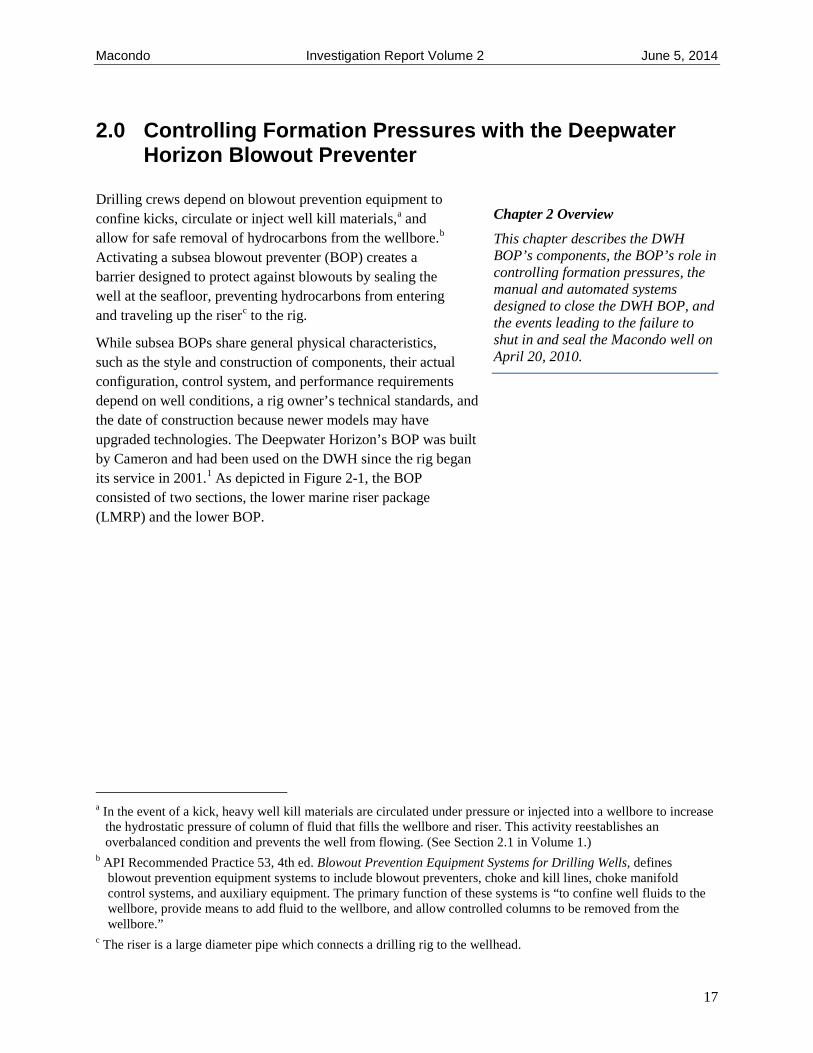
While subsea BOPs share general physical characteristics, such as the style and construction of components, their actual configuration, control system, and performance requirements depend on well conditions, a rig owner’s technical standards, and the date of construction because newer models may have upgraded technologies. The Deepwater Horizon’s BOP was built by Cameron and had been used on the DWH since the rig began its service in 2001.1 As depicted in Figure 2-1, the BOP consisted of two sections, the lower marine riser package (LMRP) and the lower BOP.
a In the event of a kick, heavy well kill materials are circulated under pressure or injected into a wellbore to increase the hydrostatic pressure of column of fluid that fills the wellbore and riser. This activity reestablishes an overbalanced condition and prevents the well from flowing. (See Section 2.1 in Volume 1.)
b API Recommended Practice 53, 4th ed. Blowout Prevention Equipment Systems for Drilling Wells, defines blowout prevention equipment systems to include blowout preventers, choke and kill lines, choke manifold control systems, and auxiliary equipment. The primary function of these systems is “to confine well fluids to the wellbore, provide means to add fluid to the wellbore, and allow controlled columns to be removed from the wellbore.”
c The riser is a large diameter pipe which connects a drilling rig to the wellhead.
Chapter 2 Overview
This chapter describes the DWH BOP’s components, the BOP’s role in controlling formation pressures, the manual and automated systems designed to close the DWH BOP, and the events leading to the failure to shut in and seal the Macondo well on April 20, 2010.
17

Macondo Investigation Report Volume 2 June 5, 2014
Figure 2-1. The DWH BOP stack
18
Macondo Investigation Report Volume 2 June 5, 2014
2.1 BOP Sealing Elements
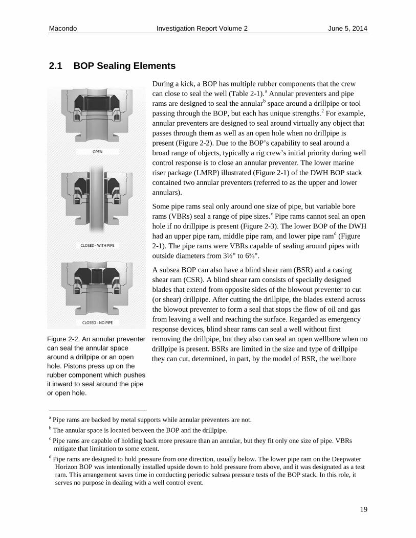
During a kick, a BOP has multiple rubber components that the crew can close to seal the well (Table 2-1).a Annular preventers and pipe rams are designed to seal the annularb space around a drillpipe or tool passing through the BOP, but each has unique strengths.2 For example, annular preventers are designed to seal around virtually any object that passes through them as well as an open hole when no drillpipe is present (Figure 2-2). Due to the BOP’s capability to seal around a broad range of objects, typically a rig crew’s initial priority during well control response is to close an annular preventer. The lower marine riser package (LMRP) illustrated (Figure 2-1) of the DWH BOP stack contained two annular preventers (referred to as the upper and lower annulars).
Some pipe rams seal only around one size of pipe, but variable bore rams (VBRs) seal a range of pipe sizes.c Pipe rams cannot seal an open hole if no drillpipe is present (Figure 2-3). The lower BOP of the DWH had an upper pipe ram, middle pipe ram, and lower pipe ramd (Figure 2-1). The pipe rams were VBRs capable of sealing around pipes with outside diameters from 3½" to 6⅝".
A subsea BOP can also have a blind shear ram (BSR) and a casing shear ram (CSR). A blind shear ram consists of specially designed blades that extend from opposite sides of the blowout preventer to cut (or shear) drillpipe. After cutting the drillpipe, the blades extend across the blowout preventer to form a seal that stops the flow of oil and gas from leaving a well and reaching the surface. Regarded as emergency response devices, blind shear rams can seal a well without first removing the drillpipe, but they also can seal an open wellbore when no drillpipe is present. BSRs are limited in the size and type of drillpipe they can cut, determined, in part, by the model of BSR, the wellbore
a Pipe rams are backed by metal supports while annular preventers are not. b The annular space is located between the BOP and the drillpipe. c Pipe rams are capable of holding back more pressure than an annular, but they fit only one size of pipe. VBRs
mitigate that limitation to some extent. d Pipe rams are designed to hold pressure from one direction, usually below. The lower pipe ram on the Deepwater
Horizon BOP was intentionally installed upside down to hold pressure from above, and it was designated as a test ram. This arrangement saves time in conducting periodic subsea pressure tests of the BOP stack. In this role, it serves no purpose in dealing with a well control event.
Figure 2-2. An annular preventer can seal the annular space around a drillpipe or an open hole. Pistons press up on the rubber component which pushes it inward to seal around the pipe or open hole.
19

Macondo Investigation Report Volume 2 June 5, 2014
pressure, and the hydraulic control systema used to power the BSR closure.b CSRs, which are stronger than BSRs, do not seal but can cut thicker drillpipe and even more difficult-to-cut casing. Subsequent sealing of a well after using a CSR would occur by allowing any remaining pipe or casing to drop into the well or to be lifted and clear the BSR before closing the BSR. The Deepwater Horizon BOP had both a BSR and a CSR located above the pipe rams in the lower BOP (Figure 2-1).
Figure 2-3. A pipe ram can seal the annular space around a drillpipe, but not an open hole without drillpipe present.
a A hydraulic control system uses pressurized fluid to open or close mechanical devices. b BOP manufacturers specify the shearing capabilities of their BSRs. See Oil & Gas UK, Guidelines on the subsea
BOP systems, Issue 1 (July 2012), p. 74.
20

Macondo Investigation Report Volume 2 June 5, 2014
In general, blind shear rams are not designed to cut threaded, thick-walled ends of drillpipe, called tool joints, though casing shear rams sometimes can. To minimize the risk of this situation, well control procedures involve clearly defined steps for spacing the drillpipe in the BOP stack to ensure tool joints are clear of the BSR.3 Table 2-1 summarizes the various BOP components.
Table 2-1. Various components of a BOP and their usesa, b (See Appendix 2-A for model numbers and capabilities of the DWH BOP elements)
2.2 The BOP as a Physical Barrier
At the time of the Macondo incident, US regulations did not address the number or effectiveness of physical barriers required to prevent the flow of hydrocarbons during drilling and abandonment operations. Current regulations require a description of the number and types of independent barriers used during drillingc,4 and a minimum of two independent barriers during completion or abandonment activities.5
a Oil & Gas UK, Guidelines on the subsea BOP systems, Issue 1 (July 2012), p. 51; A recent BSR model can shear and seal on a tool joint (GE/Hydril http://www.genewscenter.com/Press-Releases/GE-Introduces-Deepwater-BOP-Blind-Shear-Rams-with-Advanced-Capabilities-3826.aspx. Retrieved March 7, 2014.
b Pipe rams are designed to hold pressure from one direction, usually below. The lower pipe ram on the Deepwater Horizon BOP was intentionally installed upside down to hold pressure from above, and it was designated as a test ram. This arrangement saves time in conducting periodic subsea pressure tests of the BOP stack. In this role, it serves no purpose in dealing with a well control event.
c Of the two barriers required during completion activities, one of them must be a mechanical barrier as defined in API RP 65–Part 2, Isolating Potential Flow Zones During Well Construction which has been incorporated by reference in 30 C.F.R. § 250.198.
21
Macondo Investigation Report Volume 2 June 5, 2014
Internal Transocean6 and BP7 standards in place at the time of the Macondo incident also required two barriers during various phases of drilling and completion activities. In terms of the two-barrier policy, an open BOP was perceived as an acceptable barrier because it was assumed the BOP could either be closed manually to control the well during an influx of formation fluids, or automatically by backup emergency systems in the event of loss of well control.
On detection of an influx, well control response by the crew should result in the manual activation of BOP annular preventers, pipe rams, or blind shear ram through push-button panels on the rig. (See Sections 2.3.1.) Manual or automated emergency systems to seal the well might be initiated if a well control situation were to progress. On the Deepwater Horizon, the following secondary intervention control systems were designed to ensure access to BOP functions as a last line of defense against a significant unplanned event, such as a fire, riser failure, explosion, or accidental detachment of the LMRP from the BOP stack:
• The Emergency Disconnect System (EDS), manually initiated by someone onboard the rig, activated the blind shear ram and then disconnected the LMRP and riser from the wellhead;
• The Automatic Mode Function (AMF)/deadman automatically activated the blind shear ram to cut drillpipe and then seal the well in the event of a riser failure or a major explosion or fire severed communications from the rig to the BOP (the AMF/deadman did not disconnect the LMRP and riser from the wellhead);
• The autoshear system automatically closed the blind shear ram if the LMRP accidentally detached from the lower stack;
• Remotely operated vehicles (ROVs) could have been deployed to seafloor and manual activation of certain BOP functions. For example, closing the blind shear ram could have been initiated robotically.8
A BOP can act as a barrier only if it can be closed, and manual closure of a BOP by a rig crew depends on additional human and process controls, sometimes referred to as operational barriers,9 which must:
• Detect an influx into the well;
• Recognize the need to respond;
• Respond appropriately (i.e., activate the various mechanisms of the BOP to successfully seal or shear the well quickly);
• Ensure proper design and functioning of the BOP components (i.e., ensure the sealing elements and valves function as designed).
These decisions must be made before a well kick develops into a blowout, as well flow may exceed the capabilities of the BOP elements, leaving them unable to close and stop an active blowout. The first two bullets identify the reliance on drilling crew vigilance and response, suggesting that human performance is both a necessity and a threat to the effectiveness of the BOP barrier as currently designed. Volume 4 of the CSB Macondo Investigation Report details the factors that affect human response and the tools people need to complete their critical tasks effectively.
22

Macondo Investigation Report Volume 2 June 5, 2014
2.3 Functioning the Deepwater Horizon BOP
2.3.1 BOP Control System
To operate the BOP, the Deepwater Horizon had a control system that included multiple, rig-mounted control panels and two redundant subsea control pods located on the LMRP (designated as blue and yellow). Each contained two computer systems sealed in a subsea electronics module (SEM) vessel that shielded the electronics from high subsea ambient pressures.10 The yellow and blue pods worked independently of each other and contained identical sets of solenoid valves. Manually activated push buttons on the control panels sent electronic signals from the rig through armored cablesa to the yellow and blue pods that the SEMs used to open and close the solenoid valves. (See Figure 2-4.) This process allowed hydraulic fluid11 to flow through the valve, triggering the BOP functions, such as opening or closing the various rams and annular preventers.
Figure 2-4.Control panel (left) and partial closeup of control panel on the Deepwater Horizon found in the driller’s cabin and on the bridge of the rig. These controls are used to activate the BOP.12
During normal operations, or if the Emergency Disconnect System were initiated, the rig supplied the solenoid valves with electrical power and hydraulic fluid. Loss of this power and hydraulic supplies would have triggered the emergency AMF/deadman. In that case, the yellow and blue control pods each had an emergency backup 27-volt battery to power their respective solenoid valves and hydraulic fluid from backup accumulators, pressurized storage bottles, on the BOP stack (Figure 2-5).
a Armored cables: Multiplexed (MUX) cables that could send multiple simultaneous signals over a single communications cable.
23

Macondo Investigation Report Volume 2 June 5, 2014
Figure 2-5. Pressing a pushbutton on a BOP control panel sent an electronic signal through the MUX cable down to the yellow and blue BOP control pods located in the LMRP. Accumulators on the BOP stack
supplied hydraulic power to the control pods during emergencies.
24

Macondo Investigation Report Volume 2 June 5, 2014
2.3.1.1 Functioning Solenoid Operated Valves
A critical solenoid valve in the yellow pod of the Deepwater Horizon BOP was miswired, which could have prevented it from opening during the AMF/deadman sequence. (See Section 3.2.1.2.) A solenoid-operated valve, such as the one that was miswired, opens and closes as the result of an electric/magnetic action (Figure 2-6). The solenoid valve has a spring which pushes a plunger down, blocking the flow of fluid through the valve. Surrounding the spring is a tightly wound wire coil that produces a magnetic field when current runs through it. To move the plunger, the coil is energized and a resulting magnetic field attracts the iron plunger, which then pulls it up, thus allowing fluid to pass through.a
The Cameron solenoid valves on the DWH contained two separate wire coils that could be energized independently to open the valve. The solenoid valves were designed to open from the magnetic field generated by just a single coil, so the design provided redundancy to the system in case one of the coils failed.
Each coil was controlled independently by one of the two digital computers (SEM A and SEM B) contained in the SEM enclosure. During activation of the emergency AMF/deadman system, SEM A and SEM B were powered by separate 9-volt backup batteries located in the SEM enclosure. SEM A and SEM B were designed to simultaneously initiate the command to power their respective coils. Once the command was sent, the solenoid valves drew power from the shared 27-volt battery to open (Figure 2-7). If
a The converse is true as well. When power to the solenoid valve is stopped, the magnetic field disappears, and the spring pushes the plunger back to its original, closed position.
Figure 2-6. The top image depicts a solenoid with no current running through it. The plunger is down, and no
fluid can flow through the solenoid. When actuated, current running through the solenoid produces a
magnetic field which creates a force that pulls the plunger up, allowing fluid to flow.
25

Macondo Investigation Report Volume 2 June 5, 2014
either the SEM A or SEM B 9-volt battery were to fail, the initiating command would not be sent; thus, the remaining SEM would send its command, and the solenoid valve would open from one coil. If both 9-volt batteries were operable but the shared 27-volt battery failed, neither coil would receive power, and the solenoid valve would remain closed. (See Appendix 2-B for more details.)
Figure 2-7. Simplified schematic of the control pod battery arrangement.
26

Macondo Investigation Report Volume 2 June 5, 2014
2.3.2 BOP: Closing the Blind Shear Ram
Closure of the blind shear ram in a BOP may be initiated both during normal drilling operations and in emergencies. When the blind shear ram is closed and no drillpipe is in the BOP, much less force is required than when the BSR is activated to shear drillpipe. Accordingly, the DWH’s BOP had two different functions to close the BSR: the low-pressure blind shear ram close function (LP) when the BOP was free of drillpipe, and the high-pressure shear close function (HP) when shearing drillpipe was anticipated. These LP and HP functions were controlled by different solenoid valves. The EDS and AMF/deadman systems both used the HP close function, as it was necessary to account for the possibility of drillpipe in the BOP during an emergency.
The distinction between the high- and low-pressure BSR functions is highlighted here because post-incident examination of the Deepwater Horizon BSR revealed latent defects in the yellow pod HP solenoid valve responsible for closing the BSR.
2.3.3 Initiating the AMF/Deadman Sequence
On the Deepwater Horizon, the AMF/deadman had to be manually armed from one of the two control panels on the rig. Once armed,a SEM A and SEM B in each of the two control pods monitored for three conditions:
1. loss of surface electrical power and communication coming from the rig; 2. loss of communication between the yellow and blue pods; 3. loss of hydraulic fluid pressure from the rig.13
If all three conditions were met, the AMF/deadman sequence initiated. A fire and explosion like the one on the DWH could damage power and communication cables and the conduit line carrying hydraulic fluid from the rig, thus establishing the conditions necessary to trigger the AMF/deadman sequence. Once this occurred, all four SEMs would power themselves by their internal batteries and initiate solenoid valves to execute BOP functions, including closing the blind shear ram by using hydraulic fluid from the subsea accumulators. All four AMF control systems—yellow SEM A, yellow SEM B, blue SEM A, or blue SEM B—would simultaneously respond, but by design any one of the SEMs should have been able to complete the AMF/deadman sequence independently.
a Screen shots of the computer used to first examine the blue pod upon its retrieval indicate the Deadman/AMF system was still active on SEM B (BP-HZN-BLY00061078). Transocean stated a photo taken during a rig assessment on April 10 (Appendix N) shows that the Deadman/AMF on the yellow pod was also active, but upon reviewing the rig assessment report referenced by Transocean, the CSB could not confirm the photograph Transocean referenced.
27

Macondo Investigation Report Volume 2 June 5, 2014
2.4 Condition of the Well on April 20, 2010—Data Used to Recreate the Incident Events
Drillpipe pressure on the Deepwater Horizon was measured at the rig’s surface, but it was also captured in data transmissions recorded onshore.14 This data has been correlated with witness accounts to determine the actions on the rig in the hours prior to the blowout.a The following chronology focuses on the period just after the final negative pressure test was declared a “pass,” and it proceeds to the explosion at the well. (See Volume 1 for the incident description and Appendix 2-A for details of the negative pressure tests.)
The CSB also generated a computer simulationb of the Macondo well flow for the time beginning with the displacement of the drilling mud, about 4 p.m., up to the blowout that occurred near 10 p.m. (See Appendix 2-A for details concerning the simulation.) The simulation provides the basis for statements made concerning the flow of hydrocarbons from the well and inferences about the BOP’s integrity during the incident.
2.5 The Macondo Well Kicks—Incident Analysis of Well Control Response
At 8:00 p.m., after the BP wellsite leadersc and Transocean personnel completing the negative pressure test declared the test successful, displacement of the remaining drill mud with seawater began. Soon, as planned, the well became underbalanced and the hydrostatic pressure exerted on the bottom of the well went below the formation pressure. The CSB computer simulation indicates this occurred around 8:51 p.m.d The failure of the bottom hole cement job to seal the well allowed the reservoir fluids to flow into the wellbore at this time (Figure 2-8).
a While various investigating parties have reported differences in the timestamps for certain activities, these are not materially significant to understanding the sequence of events. Notes from interviews conducted by BP, http://www.mdl2179trialdocs.com/releases/release201304110900026/TREX-37031.pdf, pp. BP-HZN-BLY00377487 - 489 (Accessed August 9, 2013), just following the incident and a written statement by BP wellsite leaders, http://www.mdl2179trialdocs.com/releases/release201304041200022/TREX-51133.pdf, have been correlated with the real-time data to generate the time stamps found in this section.
b The CSB contracted with Engineering Services to complete the simulation using proprietary software. BP and Transocean completed their own simulations as well.
c Wellsite leader: The drilling supervisor overseeing all activities including heath and safety, operations, and logistics at the well, http://www.bp.com/en/global/corporate/careers/career-areas/wells/wells-operations.html. Accessed May 16, 2014.
d Others have also generated the computer model to simulate when the influx of hydrocarbons from the well began. Transocean estimated the well became underbalanced between 8:38 p.m. and 8:52 p.m. (Transocean investigation report, Volume II, June 2011, Appendix G, p. 98).The BP account was 8:52 p.m. (BP plc, Deepwater Horizon accident investigation report, September 8, 2010, p. 25.)
28
Macondo Investigation Report Volume 2 June 5, 2014
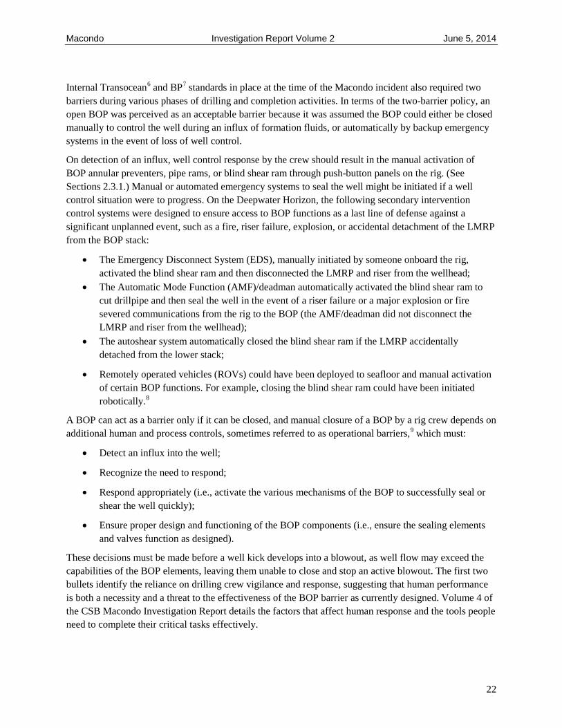
Figure 2-8. Key operation events after reservoir flow began.
Synthetic, hydrocarbon-based drilling mud is expensive, and regulations do not allow for its discharge into the Gulf;15 therefore, it is typically retained when displaced from a well and transferred to another vessel for transportation to another drilling rig, reprocessing, or proper disposal. The DWH rig had such a vessel, the Damon Bankston, available to offload the drilling mud used in the well. At 9:08 p.m., the crew believed it had finished displacing the drilling mud and prepared for a sheen testa by shutting down the pumps used to displace the drilling mud. The sheen test was used to verify that the fluids returning from the well onto the rig, referred to as “returns,” no longer contained the hydrocarbon-based mud and, thus, could be discharged overboard into the Gulf. This occurred at 9:09 p.m., when the crew declared the returns mud free and diverted their flow overboard, but the CSB computer simulation indicates that at this time the influx rate into the wellbore was sufficient to produce strong flow indicators.b
At 9:31 p.m., the driller investigated noticed an anomalous pressure difference.16 Shortly thereafter, oil and gas that had flowed into the wellbore from the reservoir pushed a mixture of seawater, drilling mud, and hydrocarbons onto the drilling rig.
In response, the drilling crew closed the upper annular (UA) at ~9:43 p.m., which should have sealed the space around the drillpipe and prevented further hydrocarbons from rising above the BOP into the riser.c
a Sheen test: A sample is added to water and a visual determination made if it causes a sheen, indicating unacceptable oil content for disposal into the sea.
b The computer simulation found in Appendix 2-A indicates about 9 bpm (barrels/minute) were flowing into the well, and the pit gain on the rig was about 60 barrels over 16 minutes.
c Witness statements said that the bridge remote control panel indicated that the lower annular was closed. Hearing before the Deepwater Horizon Joint Investigation, May 28, 2010, p. 145. However, upon recovery the lower
29

Macondo Investigation Report Volume 2 June 5, 2014
However, well data indicates that the UA failed to seal,a likely caused by erosion of the preventer rubber. Later a pipe ram with a similar rubber component and finger design successfully sealed the flow, but the pipe ram closes more rapidly than an annular, which reduces erosion potential.b As a result, not only did the riser fluids that already passed above the BOP continue to travel up the riser and release onto the drilling rig, but the riser was also being replenished by the flow of even more hydrocarbons through the leaking upper annular.
Immediately after shutting the annular, the rig crew also activated a diverter at the top of the riser to route the well fluids away from the rig floor.17 When the diverter shut, flow up the riser exiting onto the drilling rig was redirected to the diverter piping. The two potential piping destinations were overboard into Gulf waters or to a mud-gas separator (MGS).c On the day of the incident, when the crew activated the diverter, it had been preset to flow directly to the MGS.d Due to the magnitude of well fluids coming up the drillpipe, the MGS was overwhelmed moments after the diverter was activated, and hydrocarbons began blowing out of exit points onto the rig.
Pressure data indicates that at ~9:47 p.m., the crew most likely closed the middle pipe rams (MPR) and possibly the upper pipe rams (UPR), successfully shutting in the well but also causing the pressure in the drillpipe to build substantially. Riser fluids above the BOP continued to unload onto the drilling rig, but their replenishment was temporarily halted by the closed pipe ram. At ~9:49 p.m., the first explosions occurred on the rig, and data transmission from the rig to shore ceased.
Between 9:52 p.m. and 9:56 p.m., a crew member pressed the Emergency Disconnect System (EDS) button on the bridge BOP remote control panel.18 This maneuver should have closed the BOP blind shear ram and disconnected the rig and riser from the BOP, thus allowing the DWH to move away safely from the wellhead. However, there was no indication of EDS actuation. The explosion likely satisfied the criteria for automatic activation of the emergency AMF/deadman backup system by severing power, communication, and hydraulic lines to the BOP, which should have closed the blind shear ram (See Section 3.2.2), but as evident from the major oil spill that ensued, the well remained unsealed.
annular was found open [Bureau of Ocean Energy Management Regulation and Enforcement (BOEMRE), March 11, 2011. Forensic Examination of Deepwater Horizon Blowout Preventer, Report No. EP030842.] http://www.uscg.mil/hq/cg5/cg545/dw/exhib/DNV%20Report%20EP030842%20for%20BOEMRE%20Volume%20I.pdf, p. 27. Accessed August 14, 2013.
a If the annular had sealed, the drillpipe pressure at the surface would have rapidly increased to 5,000+ psig, as when the upper pipe ram sealed at 9:47 p.m. Rather, the drillpipe pressure fluctuated between 1,800 and 400 psig in this time period.
b See Appendix 2-A for more details. c When gas contamination of mud returning to the rig is suspected, well fluids can be routed to this mud-gas
separating system to safely separate and remove the flammable gas from the drilling mud. The MGS is limited in the amount of flow it can handle.
d The default lineup of the diverter was routed through the MGS for several potential reasons, including: 1) diverting through the MGS is a normal procedure while drilling; 2) discharging oil-based drilling mud overboard could be a violation of environmental regulations; and 3) diverting through the overboard lines is considered an emergency procedure, a last resort to a large influx of gas above the BOP.
30

Macondo Investigation Report Volume 2 June 5, 2014
3.0 The Blowout Preventer – Failure of a Barrier
On the day of the incident, the Deepwater Horizon BOP experienced failures that affected its ability to prevent and mitigate the Macondo blowout. The initial failure occurred approximately 6 minutes prior to the first explosion, when the drilling crew attempted to close the upper annular. If the upper annular had sealed, less gas and oil would have entered the riser and then exited onto the drilling rig, likely reducing the severity of the ensuing explosion and duration of the fire. The second failure occurred just after the explosion, when the automated emergency AMF/deadman system would have been triggered, but the blind shear ram did not close and seal the well as designed. Instead, the surviving crew had to evacuate amid an active blowout and major fire.
If either the bottom hole cement job had been successful or the BOP had functioned that day, the blowout could have been avoided. Chapter 4.3 of the Chief Counsel’s Report19 by the National Commission on the BP Deepwater Horizon Oil Spill and Offshore Drilling details the cementing process in deepwater drilling and specifically the procedures the Deepwater Horizon crew used at the Macondo well. The National Commission conducted stability studies on foamed cement20 similar to Macondo’s to further investigate a probable failure mechanism. While BP, Transocean, and Halliburton have speculated about why the cement failed, the Chief Counsel’s Report states that limitations in available data prevented determining a precise failure mechanism. Yet the report indentified several technical and management challenges that increased the risk for failure of the cement at the bottom of the Macondo well.a
Due to the National Commission’s thorough documentation of the cementing practices at Macondo in the Chief Counsel’s Report, the CSB chose to focus on the less understood failure of the BOP, which was retrieved from the wellhead and brought onshore for analysis that was not completed until after the Chief Counsel’s Report was published.
a The Chief Counsel’s Report reviewed the actions of the cement provider, Halliburton, and BP as part of its investigation. It asserts that some Halliburton personnel were aware of potential problems with the cement used at Macondo, but they did not inform BP of the issues. The National Commission attributes the lack of communication and other technical issues with the cement to management problems within the company. The National Commission was unable to specify the management problems because Halliburton did not provide any documents or testimony to indicate if the actions taken by Halliburton personnel were prohibited by the company. Beyond Halliburton, the National Commission asserts that BP’s management process did not require identifying and evaluating all the cementing risks at Macondo, which subsequently led to inadequate mitigation of them. This includes identifying risks inherent due to conditions of the Macondo well and others resulting from BP and Halliburton well design and cementing decisions.
Chapter 3 Overview
This chapter covers the CSB’s independent analysis of DWH BOP failure data, much of which was collected after other Macondo investigation reports were published, and the CSB’s additional testing. It describes latent failures found in the BOP and their effect on the emergency AMF/deadman system. The chapter also describes how large pressure differences in the Macondo well likely caused drillpipe to buckle within the BOP due to a phenomenon known as “effective compression.”
31

Macondo Investigation Report Volume 2 June 5, 2014
3.1 Correlating Physical Evidence from Macondo with the Events of April 20, 2010
Once the Deepwater Horizon blowout preventer was retrieved from the wellhead and examined, it was revealed that the drillpipe was not centered in the BOP when the BSR was activated. This off-center position of the drillpipe inhibited the BSR from fully closing and sealing the well.a Consequently, the CSB pursued three major lines of inquiry to determine the most likely cause of the bending, or buckling, of the drillpipe to its off-center position.
• Weight of equipment and drillpipe above the BOP pushing down after the support holding the top of the pipe at the Deepwater Horizon failed due to the explosion and fire;
• A combination of drag forces from high flow of well fluid up the drillpipe and from well pressure pushing up on the bottom of the drillpipe deep in the well;
• Bending forces created from the combined effects of 1) large pressure differences inside and outside of a drillpipe and 2) vertical forces applied to the face of a pipe end, a buckling mechanism referred to as effective compression, which has been previously identified in other contexts in the oil and gas industry.b
The CSB attempted to obtain BOP performance data from Cameron and BP to assess the viability of the weight theory, but neither company provided the needed information.c, d For reasons discussed in Appendix 2-A, the CSB finds the weight theory unlikelye but cannot definitively rule it out. CSB modeling indicates that if a sufficient well flow is assumed, the drillpipe may buckle, but the force from fluid flow alone is insufficient to buckle the drillpipe. Bending forces created by effective compression must be considered to calculate sufficient forces to buckle the drillpipe. The CSB concludes the most likely buckling scenario occurred just after the rig crew activated the pipe ram and temporarily sealed the
a The Deepwater Horizon BOP was not designed to cut off-center drillpipe. Post-incident modeling of the forces required to cut off-center drillpipe indicated that the DWH BOP was incapable of cutting the off-center drillpipe and subsequently sealing the well. See Appendix 2-A for details.
b See Section 3.2.3 for details. c To resolve this theory, it is necessary to quantify the force required to overcome the friction generated against drillpipe being held by closed VBRs under high well pressure. See Appendix 2-A for details. The information could be obtained from stripping performance tests or from an in-field test conducted on a drilling rig. d The CSB did not request this information from Transocean because it refused to acknowledge the Agency’s jurisdiction and failed to respond fully to subpoena requests for documents and interviews. The CSB has pursued enforcement actions in federal court. Ultimately, a federal district court ordered Transocean to comply with the CSB subpoenas. United States v. Transocean Deepwater Drilling, Inc., 2013 WL 1345246 (S.D. Tex. Mar. 30, 2013). Transocean has appealed this decision, and at the time of publication of this report, a court decision on the appeal is pending. e In summary, the closed VBRs would need to be able to support the net weight of the drill string, about 178,000 lbs. Undocumented anecdotal field experiences indicate this friction is low (10,000 to 30,000 lbs). If VBR friction were high (e.g., 100,000 to 200,000 lbs.), it could have an adverse implication for offshore drilling. An important situation occurs when deciding to hang-off drillpipe on a closed VBR. This is a well control procedure used by both BP and Transocean, and likely by other operators and contractors. If high VBR friction exceeds the weight of the drill string, lowering the drill pipe onto the rams would be impossible, potentially leaving the tool joint opposite a blind shear ram. See Appendix 2-A for more details.
32

Macondo Investigation Report Volume 2 June 5, 2014
well. This closure of the pipe ram created the pressure difference necessary for effective compression to buckle the drillpipe. (See Section 3.2.3 for details.)
Any drillpipe buckling scenario at Macondo has to be correlated with closure of the blind shear ram. Two clear opportunities arose for the BSR to have been activated:
• in the moments just after the first explosions on the DWH when the well was shut in and the AMF/deadman emergency system was likely triggered;
• on April 22 when the well was actively flowing and the emergency autoshear function was triggered by ROV intervention efforts.
Video evidence supports the activation of the autoshear function on April 22,21 but it does not preclude previous closure of the BSR as a result of AMF/deadman activation on April 20. BP, Transocean, the regulator,a the National Academy of Engineers, and the National Commission have speculated whether the AMF/deadman functioned on the day of the incident.22 The reports from these various authors were limited to the diagnostic information available on their publication date; besides the CSB, only Transocean released its report after of all phases of the Deepwater Horizon BOP failure analysis was completed.
Using the full set of BOP testing data and additional independent CSB testing, the CSB determined sufficient evidence supports closure of the BSR during the AMF/deadman activation as the most likely scenario. While this finding contradicts previously published theories, it does not negate the importance of those possible scenarios, in part because a lack of data and evidence prevents an outright rejection of some of them. Instead, in an accident as complex and devastating as Macondo, each scenario provides an important opportunity to explore previously unconsidered pipe buckling mechanisms, failures of the BOP to seal the well, and opportunities for regulations to improve safety in offshore drilling and production activities.
The CSB’s conclusion that the Macondo drillpipe likely buckled due to effective compression reveals an unrecognized potential for drillpipe to buckle even when timely well control actions initially shut in a well. Better understanding of this buckling phenomenon can lead to improvements in equipment design, well control procedures, training, and adoption of more rigorous management methods, each of which could ultimately lessen the likelihood of buckled drillpipe across the BSR of a BOP, as occurred at Macondo.
The complete set of Deepwater Horizon BOP data and additional CSB analysis extend beyond the actions on April 20 and provide new insight for safety improvements in deepwater drilling. This analysis has led to the key technical findings from the day of the incident (Chapters 3.0) and during previous drilling operations (Chapter 5.0) that address why the BOP failed to shear the drillpipe and seal the well during the incident and how post-incident regulatory and industry response has left gaps that could allow for a BOP with similar deficiencies found at Macondo to be put into service:
a At the time, the US offshore regulator was the Bureau of Ocean Energy Management Regulations and Enforcement (BOEMRE).
33

Macondo Investigation Report Volume 2 June 5, 2014
• The AMF/deadman uses two redundant control systems, the yellow pod and the blue pod, to initiate closure of the blind shear ram. This redundancy is intended to increase the AMF/deadman reliability, but on the day of the incident only one of the two pods was functioning.
o The blue pod was miswired, causing a critical battery to drain and rendering the pod inoperable (Section 3.2.1.1).
o A critical solenoid in the yellow pod had also been miswired. Redundant coils were designed to work in parallel to open the solenoid valve, but the miswiring caused them oppose one another. Had both coils been successfully energized on the day of the incident, the solenoid valve would have remained closed and unable to initiate closure of the BSR. However, a drained battery likely rendered one of these coils inoperable. This would have allowed the other coil to activate alone and initiate closure of the BSR, but drillpipe buckled off-center in the BOP prohibited the BSR from fully closing and sealing the well (Section 3.2.1.2, 3.2.1.3, and 3.2.2).
• The AMF/deadman system likely actuated, but buckled, off-center pipe in the BOP prohibited the blind shear ram from fully closing and sealing the well. The BSR punctured and partially severed the pressurized drillpipe, causing flow to resume rapidly. Flow had been temporarily stopped several minutes earlier by a successful sealing with a closed BOP pipe ram (Section 3.2.2).
• The drillpipe within the BOP buckled off-center due to effective compression, a buckling mechanism not yet identified by other investigative reports on the Macondo incidenta (Section 3.2.3).
• The BSR installed on the DWH was not suitable for the Macondo drilling operation, as it could not reliably shear the 6⅝" drillpipe used during all of the DWH drilling operations except on April 20 (See Section 5.2.1).
• The miswired solenoid valve in the yellow pod and the deficient wiring in the blue pod could not have passed the manufacturer’s factory acceptance testing procedures (Sections 5.3.1and 5.3.2).
• At the time of the incident, neither recommended industry practices nor US regulations required testing of the AMF/deadman system. Despite post-incident changes that call for function testing the AMF/deadman, deficiencies identified during the failure analysis of the Deepwater Horizon BOP could still remain undetected in BOPs currently being deployed to wellheads (Section 5.3.2).
3.2 Failure Analysis of the Deepwater Horizon BOP
a Stress Engineering Services (SES), serving under contract with Transocean, suggests effective compression to explain the pipe buckling. (Transocean, Macondo Well Incident - Transocean Investigation Report, Volume 1, 2011, Appendix M.) However, Transocean did not use the SES explanation in their investigation report. The National Academy of Engineering report notes the differences between the results of Transocean and its contractor SES, but NAE does not acknowledge that SES presents effective compression values, which include the effects of a pressure differential between the inside and outside of the pipe and account for the weight of the drill string and buoyancy forces. (National Academy of Engineering and National Research Council. Macondo Well Deepwater Horizon Blowout: Lessons for Improving Offshore Drilling Safety. Washington, DC: National Academies Press, 2011, p.50.)
34

Macondo Investigation Report Volume 2 June 5, 2014
The failure analysis of the Deepwater Horizon BOP was completed in a three-part process that began just weeks after the incident and concluded almost 14 months later (Table 3-1). The yellow and blue pods of the DWH were individually brought to the surface, and preliminary examinations were completed on May 4, 201023 and July 5, 2010,24 respectively. The solenoid valves of each pod were function tested, and the integrity of pipe, tubing, hoses, and hydraulic lines were verified.25 Additionally, execution of the AMF/deadman sequence was conducted.26
During this initial testing, neither the yellow pod nor the blue pod completed the AMF/deadman sequence correctly. The solenoid valve on the yellow pod (Y103) responsible for the high-pressure BSR shear close function would not open. All the solenoid valves on the blue pod functioned, but a critical 27-volt battery showed insufficient charge to power the solenoid valves during the AMF/deadman sequence.27 After repairs and modificationsa had been made to the pods, they were redeployed to the BOP subsea to aid intervention efforts to stop the continuing blowout using the BOP.28
Table 3-1. In addition to the three phases of DWH BOP testing from May 2010 to April 2011, the CSB completed independent exemplar solenoid valve testing in September 2012.
The Deepwater Horizon’s blowout preventer, including the yellow and blue pods, was recovered from the wellhead on September 4, 2010, and ultimately was transferred to the NASA-Michoud facility in New
a Repairs and modifications included removing the original Y103 and installing a replacement in the yellow pod. During the forensic testing of the BOP, the original Y103 was reinstalled on the yellow pod. The batteries in the blue pod were not modified during these repairs.
Results of Phase II testing are essential to understand that wiring problems in the blue pod likely caused a critical battery in AMF/deadman system to drain, which rendered it inoperable during the incident. Results also revealed that the yellow pod contained two miswired solenoid valves, one being responsible for closing the blind shear ram, which also could have rendered the AMF/deadman system in the yellow pod inoperable.
35

Macondo Investigation Report Volume 2 June 5, 2014
Orleans, Louisiana. The Joint Investigation Team (JIT) a awarded Det Norske Veritas (DNV) a contract to conduct a forensic investigation of the Deepwater Horizon BOP.29 The CSB was present for Phase I testing, and the results from this phase were made public.30
A Court Order on March 25, 2011 granted BP a motion for access to the Deepwater Horizon blowout preventer for further forensic inspection. The Court considered proposed protocols and hearings on the matter, which resulted in a Court-ordered Phase II testing protocol to be performed by DNVb under the Court’s auspices.31 The CSB was excluded from Phase II testing by the Court, but obtained the testing results and interviews to document the activities.
Complete results from Phase II testing have not previously been made public, but they are essential to understand that wiring problems in the blue pod caused a critical battery in AMF/deadman system to drain, rendering the blue pod AMF/deadman inoperable during the incident. Phase II results also revealed that the yellow pod contained two miswired solenoid valves,c one being Y103—the high-pressure shear close function solenoid—which also could have rendered inoperable the AMF/deadman system in the yellow pod.
To understand results from Phase I and II testing, the CSB also sponsored testing of an exemplar solenoid valve that determined the effect of a miswired solenoid valve. The CSB determined that despite the miswiring of Y103, a coincident failure of a battery in the yellow pod likely allowed Y103 to function on only one coil and actuate the AMF/deadman on the day of the Macondo incident. Nevertheless, the Macondo well remained unsealed because drillpipe buckled off-center in the BOP which impeded closure of the BSR. These findings are briefly summarized in this chapter with details of the full analysis provided in the supplemental technical reports on the BOP Failure Analysis in Appendices 2-A and 2-B.
3.2.1.1 Blue Pod: Disconnected Wires and the Drained Battery
Part of Phase II testing included tracing the circuitry within the SEMs to verify it matched the original Cameron drawings. The results indicate several wires from the blue pod SEM were missing, broken, disconnected, or miswired. No tests were completed to examine how, why, or when the wires came to
a The Bureau of Ocean Energy Management, Regulation and Enforcement (BOEMRE) and the United States Coast Guard (USCG) formed a joint investigation team (JIT) to investigate the Deepwater Horizon incident. BOEMRE contracted Det Norske Veritas (DNV) to conduct a physical examination of the BOP. At the request of the US House Committee on Energy and Commerce and in accordance with its statutes, the CSB initiated an independent investigation into the incident. The CSB, JIT, and other parties agreed to participate in the BOP examination. During the examination of the BOP, the CSB participated as part of the technical working group (TWG), which reviewed testing protocols and provided feedback during testing.
b During this phase of the testing, by Court order, DNV was to run the testing, produce the data, and disseminate the results to the various parties. DNV and its subcontractors were not allowed to interpret the results, provide an opinion on further testing, or write a report based on the results.
c A second solenoid, 3A in the yellow pod, was also found miswired similar to Y103. Since solenoid valve 3A controlled the upper annular regulator pressure, it was used during normal drilling operations to close off the annular space around the drillpipe. A review of the daily drilling reports from the Deepwater Horizon did not reveal any reported problems with closing pressure of the upper annular. An underlying question, then, is how could miswired solenoid 3A not have been discovered during normal drill operations when tests show neither Y103 nor 3A could have functioned normally? See How a Miswired Solenoid Valve Operates in Appendix 2-B for one possible explanation.
36

Macondo Investigation Report Volume 2 June 5, 2014
their deficient condition, but the discovery supports an alternative explanation of why a critical 27-volt battery in the blue pod was found drained. a
The CSB believes that once the AMF/deadman was armed from the rig, missing or disconnected wires in the blue pod erroneously indicated that power and communications from the rig to the pod had failed. This likelihood established one of the three conditions necessary to initiate the AMF/deadman (Section 2.3.3). As a result, the blue pod, powered by the 27-volt battery, began to monitor for loss of hydraulic pressure until the battery was drained before the day of the incident. Subsequently, the blue pod was incapable of initiating the AMF/deadman sequence during the incident due to the inability of 27-volt battery to power the opening of the solenoid valves. (See Appendix 2-B for more details.)
3.2.1.2 Yellow Pod: Miswired High-Pressure Shear Closes Solenoid
Phase II analysis of the Y103 solenoid valve from the yellow pod revealed that it had been miswired. Figure 3-1 shows where pins 1 and 3 should be attached to the white wires and pins 2 and 4 to black wires, which was not the case with Y103. As a result, when both solenoid coils were energized during bench testing, the miswiring produced opposing magnetic fields, which canceled out each other and caused the solenoid valve to remain closed.
Figure 3-1. (Left) Photograph of Y103 wire arrangement from Phase II testing with pins 1 and 4 connected to white wires and 2 and 3 connected to black wires. (Right) Schematic of correct arrangement
of wires, with pins 1 and 3 connected to white wires and 2 and 4 connected to black wires.
Previously published investigation reports assert that attempts to actuate the miswired Y103 solenoid were successful even when both coils were simultaneously energized,32 but Phase II testing revealed
a Transocean presented a theory (Transocean, Macondo Well Incident - Transocean Investigation Report, Volume 1, 2011, Appendix N, p. 6) asserting the 27-volt battery drained in the blue pod after the AMF/deadman had successfully fired on April 20, 2010. The CSB does not accept this theory, nor does it support that the blue pod successfully actuated the AMF/deadman system on the day of the incident.
37

Macondo Investigation Report Volume 2 June 5, 2014
incorrect assumptions made during Phase I. DNV believed switches on test equipment used during Phase I could control whether to energize one or two coils of a solenoid valve.33 Phase II characterization of the test equipment discovered that during an attempt to activate just one coil, both coils were energized, and vice versa. In light of Phase II information, Phase I test results needed reinterpretation. Ultimately, with just one exception, Y103 did not open when both coils were energized and always opened when just one coil was energized. (See Appendix 2-B for full details.)
3.2.1.3 Successful AMF/Deadman Tests on the Yellow Pod
The AMF/deadman was designed to simultaneously energize both coils of the solenoids it activated, yet—despite the miswiring of Y103 in the yellow pod—the system successfully completed the AMF/deadman sequence each of the three times it was initiated during Phase I testing. Although all three tests resulted in closure of the BSR, the closure was delayed during the first test.
SEM A and SEM B were powered by separate 9-volt batteries (Section 2.3.1.1). Failure of SEM A or SEM B due to a dying or dead battery would enable the miswired solenoid to function because it would prevent sending a command to the associated coil to energize. As a result, the remaining coil would function unopposed and open the solenoid valve.
Battery testing conducted during Phase II clearly shows that the SEM B yellow pod 9-volt battery failed.a Accordingly, the successful AMF/deadman test results on the yellow pod from Phase I indicate that during the first AMF/deadman test, the BSR initially failed to open until the SEM B battery died during testing operations, upon which Y103 opened. After this initial delayed response, the BSR opened without delay in all the subsequent AMF/deadman tests because the battery had been spent during the first test.
3.2.1.4 Independent CSB Exemplar Solenoid Testing
To further understand Phase I AMF/deadman results, the CSB obtained an exemplar solenoid valve and simulated the miswiring found in Y103. The CSB also simulated the effect of a battery dying while powering one of the SEMs during actuation of the AMF/deadman sequence. The CSB testing demonstrates that when both coils in a miswired solenoid are initially fired, the valve fails to open, but if the power source for one of the SEMs is cut off (i.e., a battery dies), the solenoid valve subsequently opens. (See Appendix 2-B for more details.)
For solenoid valve bench tests conducted in Phase I, a constant power source was utilized and each coil was energized separately.34 During a normal AMF/deadman sequence, both coils would be energized and the power would be pulsed to minimize heat buildup in the solenoid valve. CSB testing on the exemplar solenoid valve simulated the AMF/deadman power conditions. This testing indicates that a miswired solenoid valve could intermittently open if the two coils were activated with a small time lag to each
a The BOP battery has a very flat discharge curve over its lifecycle. The voltage will remain in operating range unless the battery is put under some type of demand (or load) by connecting it to a system that draws current from the battery. When not under load, the battery can recover some voltage after a load has been removed. No load was used during battery testing on the Q4000 and a non-representative load was used during the subsequent Phase I testing. During Phase II testing, a load that represented the normal operating condition of the 9-volt battery was used. This is when it was observed that the battery had failed. See Appendix 2-B for more details.
38

Macondo Investigation Report Volume 2 June 5, 2014
other, but this probably would only partially close the BSR.a Without evidence of intermittent opening behavior of Y103 on April 20, the CSB finds it unlikely that the miswired Y103 solenoid valve would have closed the blind shear ram during an actuation of the AMF/deadman system if both SEM A and SEM B were functioning. (See Appendix 2-B for more details.)
3.2.2 The AMF/deadman Successfully Fires on April 20, 2010
Because the miswiring in the blue pod would have caused the critical 27-volt battery to drain, rendering the pod inoperable during the incident (see Figure 3-2), the AMF/deadman sequence could actuate only if the yellow pod was able to function.
Temperature affects a battery’s performance.35 Consider a common problem automobile owners experience when they try to start a car during very cold weather. A battery does not produce as much power at lower temperatures; as a result, it can become incapable of starting a car engine. The batteries of a BOP are subject to the same limitations. Before the Macondo incident, Cameron, the manufacturer of the DWH BOP, completed AMF/deadman simulation tests that demonstrate the AMF/deadman batteries produce less completed sequences at colder temperatures.36
a The design of the BSR has a connecting rod exposed to the subsea pressure on one side and the well pressure on the other. After power to the BOP was lost due to the explosion, the pressure difference between the seawater and wellbore pressure above the closed pipe ram would have generated a closing force on the BSR. This would have pushed the BSR up to the drillpipe before the AMF/deadman sequence began. Once the AMF/deadman sequence began, further closure of the BSR to shear the drillpipe could have occurred if Y103 did open intermittently. The CSB has no evidence to support any intermittent opening behavior of Y103 on April 20, but at this time the CSB cannot definitively rule out the possibility either.
39

Macondo Investigation Report Volume 2 June 5, 2014
Figure 3-2. Miswiring in the blue pod caused the critical 27-volt battery to drain, rendering the pod inoperable during the incident. A drained 9-volt battery in the yellow pod left one of the coils in the miswired Y103 solenoid valve inoperable, allowing the other coil to activate unopposed and initiate
closure of the blind shear ram.
40

Macondo Investigation Report Volume 2 June 5, 2014
The failure of the SEM B battery during the yellow pod AMF/deadman tests in Phase I occurred when the SEM was operating in an ambient temperature near 21oC (70oF). Borrowing from the car analogy, an SEM battery that barely produced sufficient power when operating in ambient temperatures might not have functioned when operating in subsea temperatures near 2oC (36oF).a Therefore, on the day of the incident, SEM B in the yellow pod was likely not operational, allowing the SEM A coil of Y103 to function unopposed and successfully execute the AMF/deadman sequence. (See Figure 3-2 and Figure 3-3.)
The likely actuation of the AMF/deadman and closing of the BSR might have been successful during the incident had the drillpipe been centered in the BOP. However, post-incident examination of the drillpipe reveals this was not the case37 (Figure 3-4). Instead, a portion of the drillpipe was found outside of the blind shear ram blades, so it was not cut but rather squeezed between the non-blade segments of the BSR. As a result, the drillpipe was not completely severed, and the BSR did not fully close and seal the well. The partial closure of the blind shear rams punctured the drillpipe and caused flow from the well to the environment to reestablish. This reopening of the well took place minutes after closure of the pipe rams had actually sealed around the drillpipe.
a The actual temperature of the vessel containing the SEM would have been greater than the surrounding environment because of heat produced by all the electronics. Accordingly, the temperature of the SEM vessel was greater than 21oC (70oF) during Phase I and greater than 2oC (36oF) when operating subsea. Testimony given in the U.S. District Court for the Eastern District of Louisiana under the Multi-District Litigation docket MDL No. 2179, see Coronado Designations Vol. 1, p. 45, indicates the operating temperature subsea might be 16oC (60oF). Calculations in Appendix 2-B demonstrate this temperature is sufficient to affect AMF/deadman battery performance.
41

Macondo Investigation Report Volume 2 June 5, 2014
Figure 3-3. The events that led to the likely partial closure of the BSR after the emergency AMF/deadman system activated on April 20.
42

Macondo Investigation Report Volume 2 June 5, 2014
Figure 3-4. The Deepwater Horizon BOP was designed to shear centered drillpipe (left) in the BSR and then seal the well. During the Phase I examination of the BOP, the drillpipe was found off-center (right),
causing the BSR to close only partially, leaving the well unsealed.
3.2.3 The AMF/deadman Fails to Seal the Well: Buckled Drillpipe
Previous incident investigation reports have concluded that the drillpipe moved off-center as a result of forces acting to compress the pipe from the ends (axial compression) or forces created from high well flow.38 The reports did not recognize that buckling can also be caused by significant differences in pressure inside and outside of the drillpipe (differential pressure). The concept effective compression can be used to describe the combined effect of differential pressure and axial forces on pipe buckling. a
a The rigorous mathematical proofs involve either vector calculus or differential equations and may be found in one of several references: A. Lubinski, W.S. Althouse, and J.L. Logan, “Helical Buckling of Tubing Sealed in Packers,” Journal of Petroleum Technology, 14:6, (1962): pp. 655-670; S. A. Christman, “Casing Stresses Caused by Buckling of Concentric Pipes,” paper presented at Society of Petroleum Engineers Annual Fall Technical Conference and Exhibition: Paper Number SPE 6059, New Orleans, Louisiana, 1976; R.F.Mitchell, “Casing Design with Flowing Fluids, SPE Drilling and Completion, 26:3 (2011): pp. 432-435.
43

Macondo Investigation Report Volume 2 June 5, 2014
Effective compression has been well understood as a potential hazard in other oil and gas industry applications, including the design and operation of pipelines,39 well casing and well tubing,40 and of marine risers in deepwater drilling service such as those on the Deepwater Horizon.41 By incorporating effective compression, the CSB calculations show the DWH drillpipe could have been buckled at the time the AMF/deadman actuated. (See Appendix 2-A for more details on the concept presented in this section.)
Significant differential pressures leading to buckling were likely between the inside and outside of the drillpipe within the BOP. Real-time pressure data from the Deepwater Horizon indicates that the crew had successfully shut in the well just before the first explosion on the rig by closing a pipe ram. Pressure from the wellbore was contained below the pipe ram but also transmitted through the drillpipe extending through the closed ram. Above the pipe ram, the pressure outside the drillpipe was limited to just the hydrostatic pressure of the fluid in the space between the drillpipe and the riser. This pressure would have continued to drop as hydrocarbons, drilling mud, and seawater unloaded onto the rig.
Figure 3-5 illustrates conceptually the effect on a pipe when the inside pressure is much higher than outside, and how this differential pressure can cause buckling. On the left side of the figure is an ideally straight pipe. It is shown with equal pressure (represented by the arrows) acting on both the inside and outside walls. In reality, no pipe is perfectly straight, as shown in an exaggerated manner in the figure. The result of this minor inherent curvature is that the wall of the pipe on the right side is slightly longer than the left side.42 With the same pressure acting on the unequal areas of the walls, the right side of the pipe, having a larger area, actually experiences a greater net force.a If the pressure inside the pipe is increased further, the force imbalance (as a bending moment) also increases and eventually overcomes the bending resistance of the pipe, causing it to buckle.
Well pressures and forces on the drillpipe during most of the Macondo well-control event are not fully known due to the uncertainties of blowout flow rates and physical properties of the well fluids. However, a critical period occurred shortly before the initial explosion, when the well was essentially static with no new flow from the well into the riser. Computer modeling of this period presented in Appendix 2-A demonstrates that effective compression of drillpipe would have resulted in buckled, off-center drillpipe in the well as a pipe ram was closed. The subsequent explosions then likely triggered the AMF/deadman emergency system.
a Force = pressure × area
44

Macondo Investigation Report Volume 2 June 5, 2014
Figure 3-5: Theoretically straight pipe with equal inside and outside pressure (left); real pipe with a curve imperfection with equal internal and external pressure (center); pipe buckling as a result of increased
internal pressure (right). The black wedges show the relative change in length and area of the two sides of the pipe.
3.3 Conclusion
Both the manual intervention and emergency systems within the BOP were activated to shut in the Macondo well. The annular preventer activated by the crew failed to seal the well, but subsequent closure of a pipe ram did seal it. Yet, shortly thereafter an explosion on the rig likely triggered the AMF/deadman and led to the blind shear ram partially closing and puncturing the drillpipe, which reestablished flow from the well.
Both redundant control pods responsible for initiating the AMF/deadman had latent failures that could have inhibited closure of the blind shear ram. The blue pod was miswired, resulting in the draining of critical the 27-volt battery that was needed for powering the solenoid valves during the AMF/deadman sequence. A critical miswired solenoid valve in the yellow pod should have left the AMF/deadman
45

Macondo Investigation Report Volume 2 June 5, 2014
sequence unable to close the blind shear ram. The miswiring should have caused the redundant coils to oppose one another, but a drained 9-volt battery resulted in one of the coils not energizing. This left the remaining coil to activate unopposed and to initiate closure of the blind shear ram as part of the AMF/deadman sequence. Despite activation of the AMF/deadman sequence, effective compression of the drillpipe caused it to buckle off-center within the well. The blind shear ram within the BOP partially sheared this off-center pipe, but it did not seal the well. As a result, flow from the well was reestablished and the personnel on board had to evacuate amid an active blowout.
46

Macondo Investigation Report Volume 2 June 5, 2014
4.0 Establishing and Maintaining Effective Barriers
BSEE requires the management of offshore hazards,43 but it does not distinguish between hazards that could lead to a major accident like Macondo from hazards associated with day-to-day offshore operations. Barriers intended to prevent a Macondo-like accident require a different approach and go beyond the basic barrier definition, which covers a physical barrier to prevent the flow of hydrocarbons in a well. The Petroleum Safety Authority (PSA) of Norway describes barriers as “technical, operational and/or organizational elements which individually or collectively reduce opportunities for specific error, hazard or accident to occur, or which limits its harm/drawbacks.”44 This expanded definition is important because ensuring a physical barrier like a BOP can prevent or mitigate a Macondo-like accident requires additional organizational and operational elements to determine the barrier is appropriate and effective throughout its lifecycle. This concept is explored in the next two chapters.
This chapter compares the UK, Norwegian, and Australian definitions for major accidents as they relate to offshore activities and the management approaches these countries require for major accident hazards. This comparison highlights opportunities for BSEE to enhance offshore safety in US drilling operations if BSEE were to establish similar features within its safety regulations. Currently, BSEE requires an evaluation of the potential safety, health, and environmental effects that may occur if a technical barrier fails,45 but not an assessment of a barrier’s effectiveness before drilling operations begin. Furthermore, BSEE has not set forth minimum barrier performance expectations, nor does it address concepts like multiple layers of protection, the hierarchy of controls, or targeted risk reduction. As such, BSEE’s approach contrasts with international regulatory approaches to offshore safety and best practices identified for the onshore oil and gas processing facilities in the US.46
4.1 Defining the Role of a Barrier: Major Accident Events Major accidents, also referred to as major accident events (MAEs), have been defined for offshore drilling operations by governing regulations in the UK, Norway, and Australia. In the UK, offshore MAEs are defined as one of five general scenarios: 47
1. A fire, explosion or the release of a dangerous substance involving death or serious personal injury to persons on the Installation or engaged in an activity on or in connection with it;
2. Any event involving major damage to the structure at the Installation or plant affixed thereto or any loss in the stability of the Installation;
3. A collision of a helicopter with the Installation;
Chapter 4.0 Overview
This chapter examines barriers to prevent major accidents. It introduces differences between the US offshore regulatory regime and its international counterparts in how they define major accident events and safety critical elements. Also discussed are process safety concepts, including the hierarchy of controls, defense-in-depth, and Layers of Protection Analysis as tools to determine the type and number of barriers necessary to minimize the risk of a major accident event.
47

Macondo Investigation Report Volume 2 June 5, 2014
4. The failure of the life support systems for diving operations in connection with the Installation, the detachment of a diving bell used for such operations or the trapping of a diver in a diving bell or other subsea chamber used for such operations; or
5. Any other event arising from a work activity involving death or serious personal injury to five or more persons on the Installation or engaged in an activity in connection with it.a
Norway regulations have a definition that includes environmental and financial effects: “Major accident means an acute incident such as a major spill, fire or explosion that immediately or subsequently entails multiple serious personal injuries and/or loss of human lives, serious harm to the environment and/or loss of major financial assets.”48 Australia’s offshore petroleum safety regulations define an MAE as “an event connected with a facility, including a natural event, having the potential to cause multiple fatalities of persons at or near the facility.”49 BSEE offshore regulations in the US do not define major accident events.b
The risk associated with a major accident event is a combination of consequence and probability, but the rarity of MAEs can lend a perception of low risk. A Guidance Note provided by Australia’s National Offshore Petroleum Safety and Environmental Management Authority (NOPSEMA) highlights the neglect that high-consequence, low-probability events may receive: “The relative rarity of events with catastrophic consequences may give rise to the situation where potential MAEs receive little attention, as compared with day-to-day operational issues.”50 Regulations in the UK, Norway, and Australia focus on MAEs by requiring offshore oil and gas operations not only to manage high-probability personal health and safety issues, but specifically to require that MAEs be addressed. Consequently, companies operating in those offshore regions are required to establish safety management systems that explicitly address MAEs. Table 4-1 juxtaposes this approach against US regulations, which require operatorsc to have a safety management system with a goal to promote safety and environmental protection, but without a corresponding MAE requirement.d
a In this discussion references to MAE (given the jurisdiction of the CSB) concern chemical releases that could have catastrophic consequence, as opposed to ship collisions, major environmental oil spills, etc.
b US Coast Guard regulations also govern some offshore activities and do define serious marine incidents using several characteristics, including one or more deaths, injuries to crew members, and discharges of oil in excess of 10,000 gallons into navigable waters of the US, 46 C.F.R. § 4.03 (2) (2012).
c BSEE defines an operator as “the person the lessee(s) designate as having control of management of operations on the leased area or a portion thereof. An operator may be a lessee, the BSEE-approved or BOEM-approved designated agent of the lessee(s) or the holder of operating rights under a BOEM-approved operating rights assignment.” 30 C.F.R. § 250.105 (2012)
d BSEE requires the reporting of many incidents that would fall under the definition of an MAE to the District Manager immediately after their occurrence, but regulations do not require the driller or operator to take any action as a result of the incident [30 C.F.R. § 250.188 (2012)].
48

Macondo Investigation Report Volume 2 June 5, 2014
Table 4-1. Excerpts from offshore regulations from the UK, Norway, and Australia that specifically require Major Accident Events be addressed; they are juxtaposed with US regulations that promote safety and
environmental protection, but without a focus on MAEs.
4.2 Barriers to Prevent or Mitigate MAEs
In 2003, Transocean conducted a high-level generic risk assessment for the Deepwater Horizon to identify potential major accident events. The review was not well specific.a While not required for operation in the Gulf of Mexico, this assessment aimed to ensure barriers were in place to prevent MAEs or to mitigate the consequences if they did occur.51 Transocean identified and assessed several potential scenarios, two of which referenced Macondo-like events, “gas in the riser” and a “reservoir blowout.” The team completing the assessment created a table to compile the MAEs and their potential consequences as well as preventive and mitigating barriers. Table 4-2 is a sample of the one produced by Transocean.
a An analysis of Transocean’s risk assessment appears in a subsequent volume of the CSB Macondo Investigation Report.
49

Macondo Investigation Report Volume 2 June 5, 2014
Table 4-2. Recreated excerpts of Transocean's Risk Assessment for the DWH52
The “preventions” and “mitigations” listed in the table represent the safeguards designed to eliminate, prevent, reduce, or mitigate the scenario; they are also referred to as barriers, layers of protection, lines of defense, or control measures.53
BP’s Exploration and Production Operating Management System Manual identifies that barriers “are more than just mechanical or instrumented devices” but also include process and people.54, a These categories of barriers—technical, organizational, and operational—are all represented in Table 4-2.
a BP and Transocean’s implementation of risk and barrier management at Macondo is discussed in Volume 4.
50

Macondo Investigation Report Volume 2 June 5, 2014
Technical barriers include the redundant BOP controls, explosion-rated equipment, a and the hydrocarbon/combustible gas detection system. Pre-defined company routines that embrace “good drilling practices” and effective “maintenance and testing” procedures are examples of organizational barriers while “training of drill crew in well control” seeks to improve the operational barriers the crew provides when assessing and then initiating a response to a particular scenario on a drilling rig.
In its Exploration and Production Operating Management System Manual, BP warns that all barriers are prone to failure:
Even the best barrier will not achieve perfect reliability. It will have holes. The holes can be latent or actively opened or enlarged by the action or inaction of people. The robustness of the barriers changes with time, and depends on factors related to people, process and plant.55
The quote explains that barriers are vulnerable and their variable robustness affects risk by increasing the probability that a major accident event can happen. As a result, hazards should be controlled by multiple, independent layers of protection. BP indicates the best opportunity for reducing hazards is during the design stage, when inherently saferb design processes can be incorporated into the installation. The next best opportunity is in engineered safety in the form of passive or active controls,c and finally procedural safety. An effectiveness ranking of safeguards used to mitigate hazards and risks like those described by BP has also been called a hierarchy of controls. One example appears in Figure 4-1.56
Figure 4-1. Hierarchy of Controls.
Relying on multiple layers of protection to safeguard against major accident events has also been referred to as defense in depth.57 The key to defense in depth is “creating multiple independent and redundant layers of defense to compensate for potential human and mechanical failures so that no single layer, no matter how robust, is exclusively relied upon.”58 As both the concept of the hierarchy of controls and
a Explosion-rated equipment: Electrical equipment designed and constructed to be used in flammable atmospheres (e.g., flammable vapors or dusts).
b According to the Center for Chemical Process Safety (CCPS), “inherently safer design solutions eliminate or mitigate the hazard by using materials and process conditions that are less hazardous.” Center for Chemical Process Safety (CCPS), Inherently Safer Chemical Processes – A Life Cycle Approach. 2nd ed., Section 5.1.1 (2009).
c Passive controls do not require a person or system to detect an event or take action to provide protection. Active controls respond to a situation to activate devices or systems intended to interrupt a sequence of events or mitigate a consequence.
51

Macondo Investigation Report Volume 2 June 5, 2014
BP’s written programs highlight, for companies to achieve this goal,59 they must start with sound designs. If a hazard cannot be eliminated or substituted for a less hazardous one, then equipment should be built according to quality standards to avoid errors and malfunctions during operations. Equipment should have a high tolerance for malfunctions if they occur and should employ redundant systems to ensure reliability and availability. Since a defense-in-depth approach assumes mechanical and human failures will occur, layers of protection should include detection and protection systems to maintain safe operations or to shut down an operation safely when failures do occur. Finally, companies need to incorporate layers of protection that mitigate and minimize the effects of a major accident event. For example, they can plan to physically contain the release of toxic chemicals or rely on emergency response activities to minimize damage or loss of life.
4.2.1 Visualizing Barriers using a Bowtie Diagram Many plausible scenarios around a particular hazard could result in a major accident event.60 By using a visual tool known as a bowtie diagram, one can logically follow how a major accident event could evolve during these scenarios while contemplating a series of technical, organizational, and operational barrier failures.
As Macondo has demonstrated, the presence of hydrocarbons in the riser is a serious hazard. Once oil and gas pass above the BOP, no robust barrier exists to stop them from reaching the rig floor. The drilling crew must, after detection, try to divert them to a safer location, but the capabilities of the diversion equipment cannot handle a large volume of unloading riser gas. Ultimately, the hazard posed by expanding gas in the riser could progress to an ignited or unignited blowout if the release subsequently causes loss of drillpipe or BOP integrity.
A kick that results in hydrocarbons in the riser may be initiated by one of several threats, including the following examples:
• Fault during the temporary abandonment process (Volume 1, Chapter 2) • Insufficient drilling mud properties (Volume 1, Section 2.1) • Lost circulation event (Volume 1, Section 2.1) • Unexpected high pressure formation (Volume 1, Section 2.1)
These threats have been listed at the left hand side of the bowtie diagram in Figure 4-2.
52

Macondo Investigation Report Volume 2 June 5, 2014
Figure 4-2. Bowtie diagram depicting the relationships between hazards, barriers, and the major accident events they are intended to prevent.a
In this figure, technical barriers are represented along the lines connecting the threat and hazard, but only the barriers related to a “faulty temporary abandonment process” have been identified. Other circumstances could compromise the technical barriers, and, as indicated in Figure 4-3 organizational and operational barriers are in place to avoid these potential barrier decay mechanisms. b
Often different threats require different barriers. For example, the threat of “insufficient mud properties” is mitigated or avoided by having a robust well program (organizational barrier), whereas the threat of a “lost circulation” event is mitigated or prevented by the drilling crew monitoring and comparing the volume of mud leaving and returning to the rig (operational barrier). Once any of the threats in Figure 4-2
a This is not a comprehensive bowtie diagram but rather a sample of some threats, barriers, and consequences. b These are referred to as “barrier decay mechanisms” by DNV GL,
http://www.dnv.com/industry/oil_gas/publications/updates/oil_and_gas_update/2013/01_2013/more_control__better_safety_integrated_barrier_risk_management.asp ) or “escalation factors” by S. Lewis and K. Smith, Lessons Learned From Real World Application of the Bow-tie Method, presentation at the American Institute of Chemical Engineers 2010 Spring Meeting 6th Global Congress of Process Safety, San Antonio, TX, March 2010.
53

Macondo Investigation Report Volume 2 June 5, 2014
results in the presence of hydrocarbons in the riser, shared potential consequences arise. The bowtie lists several barriers intended to prevent the hazard from progressing to an ignited or unignited blowout.
Fault during temporary
abandonment
Kick resulting in
hydrocarbons in the riser
Ignited blowout:
Fires/explosions/loss of life
Unignited blowout:
hydrocarbon release into
Gulf
Bottom hole cement
Drilling fluid column
Drilling crew vigilance and
response
Emergency well control response
Diverter system
Ignition controls
Emergency BOP systems
Emergency well control response
Diverter system
Integrity tests Manual activation
of BOP
Emergency evacuation
Emergency BOP systems
Inspection and maintenance
Cement fails to seal
Correct mud density
Correct formulation
Well control procedures
BOP fails when needed
Inadequate fluid column
Design limitations identified in a
hazard analysis
Figure 4-3. Bowtie diagram showing potential decay mechanisms of the technical barriers intended to prevent a fault during temporary abandonment activities.
By tracing the lines leading from a threat to a consequence, and any barrier decay mechanisms listed, one can follow how the scenario would evolve. In the case of a fault during the temporary abandonment process, Figure 4-3 demonstrates that the following must occur:
• The bottom hole cement barrier has to fail as do the tests to detect that failure; • The drilling fluid column has to either be removed or inadequately formulated; • Well control actions by the crew have to result in failure to detect changes in density, volume,
and flow rate of the circulating (or displaced) drilling fluid column, which would indicate a kick has occurred;a
a The Transocean Well Control Handbook definition of well control principles includes “continuously monitor active pit volumes” and “immediately detecting changes in the density, volumes and flow rate of the drilling fluids from the wellbore and taking the appropriate action.” Transocean - Well Control Handbook - Level: L1B, Issue #3, Revision #1 - HQS-OPS-HP-01. Publicly accessed at
54
Macondo Investigation Report Volume 2 June 5, 2014
• The drilling crew has to then fail to activate the BOP, or the BOP fails to shut in the well upon manual activation due to inadequate design, inspection, or maintenance.
Once hydrocarbons have entered the riser, a blowout (ignited or unignited) can result if the diverter system is unsuccessful and/or ignition controls fail and an explosion occurs. The degree of fire and loss of life will escalate if the emergency well control response, BOP emergency systems, or abandonment activities do not successfully shut in the well or the crew cannot (or fails to) safely and efficiently evacuate the rig.
The BOP is the only barrier to appear on both sides of the bowtie diagram in Figure 4-2, because the BOP is a collection of well control devices and emergency systems. As described in Section 2.2, well control actions by the crew should result in manual activation of the BOP, but automated emergency shear functions may also be initiated.
4.2.2 Determining the Type and Number of Barriers to Reduce Risk
The process complexity and potential severity of an event will dictate the type and number of barriers needed to demonstrate that the risk of an MAE is reduced to a targeted level, such as “as low as reasonably practicableˮ (ALARP). Higher risk situations will require either more barriers or barriers with better reliability, and when striving for ALARP, efforts for risk reduction are instituted until the effort to
reduce risk further becomes grossly disproportionate to the level of actual risk reduction.61
In general, the UK and Australian offshore regulatory regimes accept proof of adherence to codes, standards and relevant good practice as ALARP for broadly recognized risks.62 For more complex situations, when an operator is proposing a new technology or where high-hazard scenarios affect a large population, there may not be good practice for the operator to follow or the regulator may decide industry standards are sufficient to constitute ALARP. In these situations, the regulator may consider risk assessment tools, possibly in conjunction with a cost-benefit analysis in determining if the risk of an operation has been reduced to an ALARP level. The CSB has explored concepts related to ALARP as a result of onshore investigations63 and returns to the offshore implications in Volume 3.
A company might use several tools to assess risk, including, but not limited to,
• Risk Matrix
http://www.mdl2179trialdocs.com/releases/release201303071500008/TREX-00596.pdf, Section 2 (Well Control Principles), Subsection 1 (Definition).
The Principle of ALARP
“As low as reasonably practicable” was first defined legally in English courts in 1949.a Lord Justice Asquith suggested that “physically possible” is distinct from “reasonably practicable.” “Reasonably” should be determined by comparing the time, money or effort necessary to reduce risk. If one can show that “the risk [is] insignificant in relation to the sacrifice,” then the onus of further expenditure is dismissed. This concept is explored more fully in the CSB’s Macondo Investigation Report, Volume 3.
55

Macondo Investigation Report Volume 2 June 5, 2014
• What-if Checklist • Hazard and Operability Study (HAZOP) • Facility Siting study • Qualitative Risk Assessment (QRA) • Layers of Protection Analysis (LOPA).64
As part of LOPA, independent layers of protection (IPLs) are analyzed for their effectiveness, and their combined protection is measured against risk tolerance acceptance criteria.a,65 This approach is explored in depth here more than the others because, as discussed in Section 5.2.2, a movement is afoot toward using the technique to define BOP performance requirements.
IPLs are devices, systems, or actions capable of preventing an initiating event from progressing to an undesired consequence. The LOPA method uses event severity, initiating event frequency, and likelihood of failure of the IPLs to calculate a level of risk. If the calculated risk level as determined by LOPA is not considered acceptable, then additional IPLs can be added to a scenario, and the analysis can be repeated. As a result, LOPA is used to evaluate the value of implementing additional protection layers with the goal of reducing risk to below a maximum acceptable threshold.
Applying LOPA requires clearly defining the initiating event, and each IPL must be: 1) independent of the initiating event and each other, 2) effective in preventing the consequence when it functions as designed, and 3) auditable so that its performance can be validated.66 These factors imply that not all barriers, or safeguards, can be IPLs for calculating a risk level during LOPA. For example, training and procedures are important safeguards for preventing an accident, but their failure may cause the initiating event, in which case they could not be considered independent layers of protection in the LOPA context.67
LOPA can be used to describe IPL performance by calculating the average probability the IPL will perform its required safety functions under stated conditions and within a stated time period.68 An industry benchmark contextualizes this performance for instruments or equipment by assigning them a discrete value called the safety integrity level (SIL).69 An SIL ranges from one, the lowest performance level to four, the highest. The higher the SIL, the greater the probability the instrument or equipment will function to successfully prevent an undesired consequence. Each integer
a BP has a group practice that describes the LOPA methodology, GP 48-03 Layers of Protection Analysis (LOPA): Groups Practice – BP Group Engineering Technical Practices (ETP), 5 June 2008 [BP-HZN-CSB00181723]. GP 48-03 also includes references to hazard and operability studies (HAZOP) and inherently safer design options. The ETP was expressly approved “for implementation across the BP Group,” which included drilling, but was acknowledged in BP Board records [BP-HZN-BLY00204248] not to have been applied to contractor MODUs in the Gulf of Mexico at the time of the Macondo incident. Volume 4 of the CSB Macondo investigation report analyzes risk assessment at Macondo in greater depth.
Defining the Initiating Event
Identifying all well control situations that could progress to a blowout is critical to avoid calculating an artificially low level of risk.
In 2009, Transocean reported six kicks that resulted in uncontrolled release of mud and gas onto a rig after well fluids passed above a BOP. Any kick has the potential to develop into a blowout. The number of well control incidents per rig increases from 0.05 to 0.6 when considering the total number of kicks (71).† †Transocean Annual Report 2009, Well Control Events & Statistics 2005 to 2009, TRN-INV-01143142.
56

Macondo Investigation Report Volume 2 June 5, 2014
increase in SIL corresponds to a ten-fold reduction in the risk frequency that an initiating event will result in the corresponding event consequence. Assigning an SIL to an instrument or piece of equipment accounts not just the initial design; it considers the complete lifecycle, including maintenance and testing. This judgment requires verification of the actual performance of the IPL throughout its lifetime to ensure the availability of the safety integrity action is maintained.70
4.2.3 Maintaining Effective Barriers
LOPA and SIL assignments offer one approach to help demonstrate ALARP, but characteristics of effective barriers also can be summarized more generally. NOPSEMA contends that clear linkages between the barriers and the specific hazards they are designed to prevent and mitigate will aid drilling operators in effectively determining if those barriers:
• have been selected in accordance with the hierarchy of controls (order of preference); • are distributed appropriately with representation of the types of control, namely, engineering,
procedural, and administrative; • have adequate layers of protection; • cover the full range of operating and emergency circumstances; • consider common mode failures; • are effective; • are reasonably practicable; • reduce the risk to a level that is ALARP.71
Continuously monitoring a barrier’s effectiveness throughout its lifecycle is a prominent requirement for international regulatory regimes governing offshore drilling operations.72 In Norway, regulations require performance standards to continuously monitor threats to barriers: “the operator or the party responsible for operation of an offshore or onshore facility, shall stipulate the strategies and principles that form the basis for design, use and maintenance of barriers, so that the barriers’ function is safeguarded throughout the offshore or onshore facility’s life.”73 These strategies and principles are often embedded within a company’s safety management systems (SMSs).
In part, a company’s SMSs ensure the barriers are available, reliable, independent, and effective. Success of an SMS program requires implementing several organizational process assurances, including a mechanical integrity program for the equipment functions as expected; a training program for the human control to have the skills and aptitude to handle the potential hazards/risks of the work, particularly for safety critical tasks, such as responding correctly to an emergency event; and a management of change program for not detrimentally affecting the barriers in place during changes to the drilling plan, equipment, crew, or management. The relationship among these barriers is interdependent. If a piece of equipment fails unexpectedly despite following the planned preventive maintenance inspection schedule, the reliability of the barrier should be reassessed and the mechanical integrity program adjusted to ensure that such a failure cannot recur. Otherwise, the reliability of the barrier does not match performance and the risk levels increase. Ideally, the company would not wait until a failure occurs to assess the health of a barrier, but rather incorporate indicators to measure the ongoing health of the barrier and communicate regularly to the regulators, workforce, and management.
57

Macondo Investigation Report Volume 2 June 5, 2014
4.2.3.1 Barriers as Safety Critical Elements (SCEs)
The role of SMS is particularly important when the barrier being monitored is equipment or a human action whose:
• failure could cause or contribute to a major accident event; • purpose is to prevent or limit the effects of a major accident event.
Offshore regulations in the UK refer to such barriers as safety critical elements (SCEs)74 or, in the case of human actions, safety critical tasks.a One author described SCEs in these simple terms: “These are the safety controls (hardware, people systems, or software) that deliver a disproportionate improvement in safety (and conversely, when not functional lead to a disproportionate increase in risk).”75
Companies operating offshore in UK,76 Norway,77 and Australia78 must identify safety critical elements and establish performance standards, which are qualitative or quantitative statements that describe the required performance of the SCE. Performance standards can be based on nationally and internationally recognized industry standards, but they may also comprise methods or technical solutions developed by the company.79
In 2005, the Energy Institute published revised guidanceb to provide good practice for offshore installations to follow in managing safety critical elements.
The guidance defines performance standards in terms of:
1. Functionality — What is it required to do? 2. Availability — What will be its performance duration? 3. Reliability — How likely is it to perform on demand? 4. Survivability — What post-event role must it survive to perform? 5. Interactions — What other systems must be functional for it to operate?
Compliance with an appropriate performance standard is the basis for assuring an SCE will act as a barrier to an MAE. In the UK, a written verification scheme, based on the SCE’s performance standard, is required to ensure every SCE is appropriate, available, and effective throughout its service.80
a UK Safety Case regulations do not specifically require naming safety critical tasks, but UK HSE Safety Case guidance states, “Human performance problems should be systematically evaluated. This should involve evaluating the feasibility of tasks, identifying control measures and providing an input to the design of procedures and personnel training, and of the interfaces between personnel and plant. The depth of analysis should be appropriate to the severity of the consequences of failure of the task.” UK HSE, Assessment Principles for Offshore Safety Cases, http://www.google.com/url?sa=t&rct=j&q=&esrc=s&source=web&cd=1&cad=rja&sqi=2&ved=0CDUQFjAA&url=http%3A%2F%2Fwww.hse.gov.uk%2Foffshore%2Faposc190306.pdf&ei=jg6OUuTzHaPhygHI7YE4&usg=AFQjCNG9jDdqxIdUGguRCSNxT6GUoIozCg&sig2=6n2lF5b6kPPIzyXlEZA0cA&bvm=bv.56988011,d.eW0. Retrieved November 21, 2013.
b After the UK Safety Case regulations were instituted in 1996, Oil and Gas UK (formally the UK Offshore Operators Association) created guidance for the management of safety critical elements. This original guidance was revised by the Energy Institute, Guidelines for the Management of Safety Critical Elements, 2nd ed.
58

Macondo Investigation Report Volume 2 June 5, 2014
While Norway and Australia do not cite verification schemes by name, each country has regulatory language or guidance that mirrors the verification scheme requirement in the UK.81
In the absence of a verification scheme, a risk assessment could result in an activity that identifies an MAE and then simply assigns what are assumed to be SCEs, but which do not actually reduce the probability or consequence of the MAE. As the UK Health Safety Executive (HSE) states, “Risk assessment alone does little or nothing to reduce risks, particularly if the risk assessment is seen as an end in itself. Rather, risks are reduced by employing the risk assessment process in an active and intelligent way, as a tool to help focus the process on continuous improvement within the safety management system.”82
In any regulatory regime, there is the potential for performance standards and verification schemes to be generated, but then put on a shelf and do little to actually increase the safety offshore operations. In this manner the regulatory requirements could become a documentation exercise rather than an integrated part of a normal work process. Continuous improvement to reduce the risk of a major accident event requires looking beyond current good practice and naturally implies that ALARP, or any risk reduction target, is a constantly evolving concept. In some instances companies will initiate the push for improvement and in other instances the regulator can lead the way, but only if the regulatory framework is in place to facilitate the process for all parties. The following callout box describes one such example.
The written verification scheme
Also called an assurance scheme, the written verification scheme should ensure the SCE performance is met by:
(1) Identifying those assurance activities, such as maintenance, inspection, and testing, which are required to sustain the SCE in a suitable condition;
(2) Ensuring that these activities are carried out at the appropriate time by competent people;
(3) Maintaining a record of these activities and any findings that arise; and
(4) Addressing any deficiencies arising from assurance activities as soon as possible and taking any temporary measure that may be necessary to maintain risk ALARP until deficiencies have been recertified. Any temporary measures should be subject to review and comment by an independent competent person. † † Guidelines for the Management of Safety Critical Elements, 2nd ed. published by the Energy Institute.
59

Macondo Investigation Report Volume 2 June 5, 2014
The Power of Risk Reduction Targets
Norway’s offshore safety regulator, the Petroleum Safety Authority (PSA), continuously drives improvements in safety by requiring responsible parties to ensure that risks are “reduced beyond the established minimum level … if this can take place without unreasonable cost or drawback.” For instance, in 1992 PSA sought to introduce regulations to require the use of remote-operated pipe handling technologies to reduce work-related injuries associated with handling heavy-duty piping. Numerous complaints were lodged against the regulations; however, PSA enacted the requirements because the social benefits outweighed the cost of compliance. Through a collaborative partnership, industry and regulator worked together to develop technologies capable of improving safety. The result has been a marked improvement in pipe handling safety. Furthermore, due to the global nature of the industry, pipe handling safety improvements have been adopted worldwide. Thus, regulatory initiatives to redefine what is “practicable” or “beyond the minimal level” can result in significant safety change.
Sources: Petroleum Safety Authority Norway, unless noted otherwise, from the following publications, last visited February 7, 2013:
• Guidelines Regarding the Framework Regulations, Re Section 11 Risk Reduction Principles, http://www.ptil.no/framework-hse/category408.html#p11;
• 081 – Norwegian Oil and Gas Recommended Guidelines for Remote Pipe Handling Operations, http://www.norskoljeoggass.no/Documents/Retningslinjer/081-100/081%20-%20Recommended%20guidelines%20for%20remote%20pipe%20handling%20operations%20rev.4,%2011.06.12.pdf?epslanguage=no;
• Regulations Relating to Health, Safety and the Environment in the Petroleum Activities and at Certain Onshore Facilities (The Framework Regulations), Section 11 Risk Reduction Principles. http://www.ptil.no/framework-hse/category403.html#_Toc282603288;
• Mechanical Pipe Handling: Reviled Requirements Paid Off (2011) , http://www.ptil.no/news/mechanical-pipe-handling-reviled-requirements-paid-off-article7666-79.html?lang=en_US
• Invented Safety, Reaped Values (2007), http://www.ptil.no/news/invented-safety-reaped-values-article3341-79.html;
• Kevin Roche, Noble Pipe Handling Incident Review – Gulf of Mexico, http://www.ptil.no/getfile.php/z%20Konvertert/Helse%2C%20milj%C3%B8%20og%20sikkerhet/Sikkerhet%20og%20arbeidsmilj%C3%B8/Dokumenter/presentation%2B%2528noble%2B-%2Bpipe%2Bhandling%2Bincident%2Brev.pdf.
60
Macondo Investigation Report Volume 2 June 5, 2014
4.3 Conclusion
A natural tendency is to focus on technical barriers because they are physical in nature, and in deepwater drilling they clearly show how they stop the flow of hydrocarbons from the well. Yet all barriers, whether technical, operational, or organizational, are prone to failure; therefore, multiple barriers of sufficient robustness are required to avoid a major accident event. The number of barriers needed to reduce the risk of an MAE may simply require following good guidance practices established by the industry, or they may require additional risk assessment tools to evaluate whether risk has been reduced to some targeted level, such as ALARP.
61

Macondo Investigation Report Volume 2 June 5, 2014
5.0 Deepwater Horizon BOP not Treated as a Safety Critical Element
A blowout preventer contains multiple well control devices, and it satisfies both definitions of a safety critical element given in Section 4.2.3.1: it is a device intended to prevent a kick from progressing to a blowout and to mitigate potential consequences of a blowout—fatalities, major oil spill, and loss of rig. While Transocean and BP conducted routine inspections and weekly functioning of various operational components necessary for daily drilling operations, they failed to implement inspection and testing activities that would have identified latent BOP failures of the emergency systems components of the Deepwater Horizon BOP. As a result, the safety critical BOP systems responsible for shearing drillpipe in emergency situations were compromised before the BOP was even deployed to the Macondo wellhead.
While this chapter uses the BOP as the vehicle to explore effective management of safety critical elements, the other barriers listed in the bowtie diagram from Section 4.2.1 could be subjected to the same analysis. The bowtie diagram demonstrates that failure of a technical barrier, such as the BOP, is rooted in inadequate operational and organizational barriers. The links between these barriers—technical, operational, and organizational—and major accident events provide a means to identify the systems that operators and regulators should monitor for opportunities to improve risk reduction.83
Organizations maintaining effective safety critical elements (SECs), such as the BOP, implement management activities to ensure they meet safety objectives throughout the lifetime of the SCE.84 These measures appear in the simplified representation of the management system for the lifecycle of an SCE in Figure 5-1.
Chapter 5.0 Overview
This chapter discusses the BOP as a safety critical element and provides evidence to support that BP and Transocean did not treat it as such. Also reviewed is the lifecycle of a safety critical element, which includes identification, development of performance standards, assurance and verification activities, and gap closure.
62

Macondo Investigation Report Volume 2 June 5, 2014
Figure 5-1. Simplified representation of the management system for the lifecycle of a safety critical
element
While Transocean identified the Deepwater Horizon BOP as safety critical in a hazard analysis, it operated the BOP beyond its design limits for reliable drillpipe shearing and did not track modifications to individual components that ultimately affected the reliability of the emergency systems. As required by regulations,85 regular testing of some BOP functions was performed, but this testing did not assess the emergency systems and were could not detect the latent failures presented in Chapter 3.0. The CSB concludes that post-incident testing changes now required in the United States are not sufficient to ensure industry will detect deficiencies like those found in the Deepwater Horizon BOP.
Using the Deepwater Horizon BOP as a model, this chapter highlights opportunities throughout the SCE lifecycle to use or improve effective identification, performance standards, and assurance and verification activities to guarantee a BOP is effective throughout its use. This information culminates with a discussion on gap closure intended not only to maintain the performance of a BOP and the operational and organizational barriers that support it, but to improve them over time.
The CSB concludes that post-incident BOP testing changes now required in the United States are not sufficient to ensure industry will detect deficiencies like those found in the Deepwater Horizon BOP
63

Macondo Investigation Report Volume 2 June 5, 2014
5.1 Identification of a SCE
Failure of safety critical elements and tasks could cause or contribute to major accident events. (See Section 4.1.)86 Operators and drilling contractors should clearly document SCEs to distinguish them from other equipment and tasks.a The first step in identifying them depends on determining potential major accident events through a hazard analysis (Figure 5-1),87 which should identify the sequence of events that could lead to a major accident and the factors that can contribute to it, including human errors.88 Companies will typically use internal equipment lists as a starting point for identifying safety critical elements, but the depth to which they should define the SCEs depends on their direct link to the major accident event.89 For example, while a BOP as a whole is safety critical, not every component of a BOP necessarily is.
5.1.1 BOP Component Failure Identified in DWH Hazard Analysis In the 2003 Major Accident Hazard Risk Assessment conducted by Transocean,90 a Statement of Approval that accompanied the MAHRA reads:91
The [MAHRA] performed for the Deepwater Horizon identified reasonably foreseeable hazards that might lead to a major accident. It has been demonstrated that adequate controls are in place so that HSE [health, safety, and environmental] risks on the Deepwater Horizon can be considered both tolerable and ALARP (As Low As Reasonably Practicable). This assessment has been reviewed and recommendations which were developed have been followed up.
The MAHRA identified the BOP system as “critical” and recorded hazards specific to the BOP system that could lead to a major accident. The MAHRA also documented the preventions and mitigations related to the BOP system. One of the hazards listed for the BOP system was “a component failure,” which, in light of the evidence presented in Section 3.0, is appropriate since the failure of a solenoid or battery in a BOP could be sufficient to inhibit the emergency AMF/deadman system. The accompanying consequences, preventions, and mitigations associated with a component failure, as identified by Transocean, are listed in Table 5-1.
a The term “safety critical element” is akin to American National Standards Institute’s use of “process safety safeguardˮ when addressing risk management in the process industry in the ANSI/ISA-84.91.03-2012, Identification and Mechanical Integrity of Safety Controls, Alarms, and Interlocks in the Process Industry, September 20, 2012, p. 12.
64
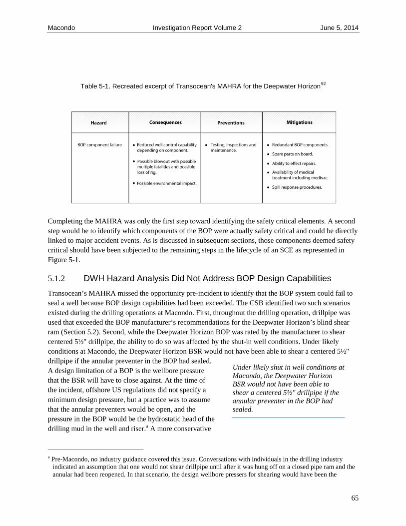
Macondo Investigation Report Volume 2 June 5, 2014
Table 5-1. Recreated excerpt of Transocean's MAHRA for the Deepwater Horizon92
Completing the MAHRA was only the first step toward identifying the safety critical elements. A second step would be to identify which components of the BOP were actually safety critical and could be directly linked to major accident events. As is discussed in subsequent sections, those components deemed safety critical should have been subjected to the remaining steps in the lifecycle of an SCE as represented in Figure 5-1.
5.1.2 DWH Hazard Analysis Did Not Address BOP Design Capabilities Transocean’s MAHRA missed the opportunity pre-incident to identify that the BOP system could fail to seal a well because BOP design capabilities had been exceeded. The CSB identified two such scenarios existed during the drilling operations at Macondo. First, throughout the drilling operation, drillpipe was used that exceeded the BOP manufacturer’s recommendations for the Deepwater Horizon’s blind shear ram (Section 5.2). Second, while the Deepwater Horizon BOP was rated by the manufacturer to shear centered 5½" drillpipe, the ability to do so was affected by the shut-in well conditions. Under likely conditions at Macondo, the Deepwater Horizon BSR would not have been able to shear a centered 5½" drillpipe if the annular preventer in the BOP had sealed. A design limitation of a BOP is the wellbore pressure that the BSR will have to close against. At the time of the incident, offshore US regulations did not specify a minimum design pressure, but a practice was to assume that the annular preventers would be open, and the pressure in the BOP would be the hydrostatic head of the drilling mud in the well and riser.a A more conservative
a Pre-Macondo, no industry guidance covered this issue. Conversations with individuals in the drilling industry indicated an assumption that one would not shear drillpipe until after it was hung off on a closed pipe ram and the annular had been reopened. In that scenario, the design wellbore pressers for shearing would have been the
Under likely shut in well conditions at Macondo, the Deepwater Horizon BSR would not have been able to shear a centered 5½" drillpipe if the annular preventer in the BOP had sealed.
65

Macondo Investigation Report Volume 2 June 5, 2014
approach would have been to assume that an annular preventer was closed and the BSR would have to close against the maximum anticipated surface pressure (MASP)a for the well. (See Appendix 2-A for more details.) The Deepwater Horizon accumulator system was not designed to overcome the increased wellbore pressure that would have occurred at Macondo if the DWH annular preventer had been closed. BSEE regulations now require that the blind shear ram be able to shear against maximum anticipated surface pressure (MASP).93
5.2 Defining Performance Requirements of a SCE Ultimately, the performance standard is the basis for how an SCE will reduce the risk of a major accident event.b, 94 Operators and drilling contractors can use a performance standard to define the safety critical element’s requirements during all phases of an operation and to address the hazards or potential MAEs that could occur during operational activities.95
The performance requirements for an SCE should include all the aspects described in Section 4.2.3.1—the functionality, availability, reliability, survivability, and interactions with other systems that may affect its ability to function properly. The performance requirements should also be verifiable to ensure the SCEs are suitable for the hazards identified in the hazard analysis. Verification may include clarifying the relationship between the hazard analysis and the role of the SCE. For example, a BOP is not designed to stop an active blowout, so ideally it will be activated before oil and gas pass above the BOP.96 The performance standard may identify safe operating limits, setpoints, or criteria for action to place an operation in a safe state.97 By implication, the performance standard will include measures to compensate for out-of-service periods.98 Performance requirements should cover both normal and abnormal situations, including when to respond manually, what actions to take, and in what state to leave the process. Determining the reliability of an SCE will require an accurate estimate of the demand rate on the equipment, as an increased rate could affect reliability predictions.99 Equipment should meet these requirements, and its approval might be based upon manufacturer’s information and historical in-house performance within the organization.100
5.2.1 Drillpipe Exceeded Shearing Capabilities of DWH Blowout Preventer The Transocean well control manual, in effect at the time of the incident, states minimum acceptable requirements for BOPs on all company installations. It does not address all of the performance requirements listed in the preceding paragraph, but the manual does include the following performance statements:
• There must be at least one set of blind/shear type rams; • The blind/shear rams must be capable of shearing the highest grade and heaviest drillpipe used on
the rig … and sealing the well in one operation.101
hydrostatic pressure of the mud column. The Macondo incident demonstrated that this assumption was not adequate. The BP and Transocean well control manuals state that the blind shear rams should be capable of sealing the well in one operation [BP-HZN-2179MDL00327390], that the limitation of the shear capacity should be understood, and that plans should be in place to address any limitations [BP-HZN-CSB00079397].
a MASP: Maximum anticipated surface pressure, the maximum pressure that may occur in a well. b Section 4.2.3.1 introduces performance requirements in the form of a performance standard.
66
Macondo Investigation Report Volume 2 June 5, 2014
The Deepwater Horizon’s BOP met the first performance requirement—but the blind shear ram did not meet the second requirement. At the time of the incident, the DWH had 5½" drillpipe in the BOP, but for most of the drilling at Macondo, 6⅝" drillpipe was used.102 The Deepwater Horizon BOP was not capable of reliably shearing 6⅝" drillpipe.
In 2007, Cameron published a product advisory “to assist Cameron equipment users in defining the shearing requirements for drilling operations.”103 Cameron provides a “method that can be used as a guide to predicting if a tubular [e.g., drillpipe] is shearable or not.” The formulas given in the method are based upon empirical data Cameron has collected over the years to validate the ability of a BOP to shear drillpipe. Calculated results based on the method provided in the product advisory demonstrate that the Deepwater Horizon’s BSRa did not meet the manufacturer’s most recent published design shearing capabilities for 6⅝" drillpipe.b
Emails exchanged (Table 5-2) indicate that at least one of the DWH senior subsea supervisors was aware the rig BSR was not rated to shear 6⅝" drillpipe.104 As a result, Transocean had a multistep workaround for the larger pipe,105 but the procedure contradicted the “one operation” performance requirement Transocean set in its well control manual. The workaround was to first shear the 6⅝" pipe with the casing shear rams, which can shear the heavier pipe but not seal the well, and then close the BSR with no pipe in it. This method could be accomplished manually by the driller or by setting the Emergency Disconnect System into a mode designed to complete this type of two-step operation.c However, the AMF/deadman system was not programmed to perform this two-step operation. This protocol increased the risk of a major accident event, because activating the AMF/deadman with the 6⅝" drillpipe would have exceeded the BOP design capabilities, immediately leading to a well blowout.d Best practice recommends identifying the interactions of an SCE with other systems because a change to a system may negatively affect the SCE. The two-step operation is an example of a negative impact to an SCE, highlighting the need for establishing management of change procedures for safety critical equipment.e (See Appendix 2-A for more details.)
a The Deepwater Horizon BSR was a Cameron model TL 18 3/4" (15,000 psi WP) with a type-SBR shear packer. b When the DWH was completed in 2001, its BOP manual (using then-current Cameron ratings) listed the BSR as
capable of shearing 6⅝" pipe (Deepwater Horizon TL BOP Stack Operation and Maintenance Manual; Cameron Engineering Bulletin 702D (August 1991, Rev. B1), p. 6; CAM-CSB 000005989). Also, a well control equipment commissioning report to BP stated the BSR was sufficient for 6⅝" pipe, apparently also based on the then-current Cameron bulletin (Report of Well Control Equipment Commissioning, by In-Spec Inc. (March 2001); BP-HZN-BLY00058800, BP-HZN-BLY00058786.
c The EDS can be set to operate in Mode 1 or Mode 2. Mode 1 just closes the BSR. Mode 2 was intended for use when casing was being transferred into the well. Mode 2 closed the CSR first and then the BSR.
d Another automated emergency system, the autoshear function, could not access the CSR either, so it would have had the same limitations as the AMF/deadman system in shearing 6⅝" drillpipe. The autoshear function is triggered from a valve sensor installed in the BOP to detect an accidental disconnect of the LMRP, at which time it initiates closure of the blind shear ram.
e As defined by the Center for Chemical Process Safety, “Management of change is the process for evaluating and controlling modifications to facility design, operation, organization, or activities—prior to implementation—to make certain that no new hazards are introduced and that the risk of existing hazard to employees, the public, or the environment is not unknowingly increased.” Guidelines for Management of Change for Process Safety. Center for Chemical Process safety/AIChE, 2008.
67

Macondo Investigation Report Volume 2 June 5, 2014
At the time of the incident, BP covered the treatment of the BOP in an engineering technical practice (ETP) for well control,106 which includes, “the essential systems, practices, and training requirements that comprise the BP well control standard.” The ETP lists several prescriptive requirements for the BOP, including the configuration of preventers (e.g., annular preventers, pipe rams, shear rams). The ETP states, “The limitations of its [the BSR’s] shearing capacity should be known and understood, and a documented risk assessment shall be in place to address any such limitation.” The CSB did not find any documented risk assessment by Transocean or BP to address operating the Deepwater Horizon BOP outside of the manufacturer’s recommended shearing capacity. The ETP also does not require users to operate within the shearing capacity of the BSR or to ensure temporary measures that maintain safety and/or reduce risk.
Table 5-2. Summary of emails sent between Transocean personnel regarding BSR shearing capability.
Contrary to Cameron’s advice in its shearing guide, the DWH BSR did successfully shear 6⅝" drillpipe when an EDS function was executed in June 2003.107 This experience shows that the BSR employed by the Deepwater Horizon could sometimes shear the larger sized drillpipe, but it does not establish that the action is reliable.
5.2.2 Prescribing Minimum Reliability Requirements of a BOP Safety Integrity Level is a discrete measurement that indicates the reliability of a barrier.a the greater the SIL, the greater the probability a barrier will perform its required function upon demand. Establishing an SIL involves making assumptions about the barrier’s availability. For example, shearing the 6⅝" drillpipe required a two-step process not available to the AMF/deadman sequence; thus, it would clearly affect the emergency system’s reliability even if all the individual components of the system (e.g., batteries, solenoid valves) were fully functioning. Some effort to define the SIL for BOP functions has intended to reduce risk to a targeted level, such as ALARP. But uncertainty remains about establishing an SIL for the BOP shearing function; as a result, a recommended practice is to rely upon the published BOP manufacturer’s guidance.
a Section 4.2.2 introduces the concept of Safety Integrity Level.
68

Macondo Investigation Report Volume 2 June 5, 2014
The BOP can be analyzed as a safety instrumented system that,a after being actuated manually or automatically, reestablishes a safe condition by sealing a well with annular preventers, pipe rams, or a blind shear ram. The international standard IEC 61511 has been accepted as the basis for specification, design, and operations of safety instrumented systems (SIS) in the process sector.108 The risk-based approach described in IEC 61511 would require employing one of several suggested methods to determine the SIL of a BOP. All of these methods would depend upon the user making assumptions about the reliability of various components of the BOP.109 Ultimately, the different methodologies and assumptions could lead companies to identify inconsistent SIL requirements for a BOP.110
In an effort to encourage standardization across the industry, Norwegian Oil and Gas Guideline 070 proposes the use of a predefined minimum SIL to ensure a minimum level of safety for the most common safety functions on petroleum installations.111 PSA management regulations in Norway specifically cite the Norwegian Oil and Gas Guideline 070 as the basis for barrier performance, meaning the guidance and the minimum SIL it contains are enforceable on the Norwegian Continental Shelf. b Guideline 070 addresses three standard BOP functions:
1. sealing around drillpipe; 2. sealing an open hole; 3. shearing drillpipe and sealing a well.112
After detection of a kick, one of these three BOP functions may require activation to prevent a blowout.c For functions one and two, Guideline 070 establishes a minimum required SIL of 2, which implies the probability of the BOP function failing when activated after kick detection is less than 1 in 100 actuations.d Ensuring an SIL of 2 is maintained for the BOP functions will require companies to validate the performance of the BOP actively. (See Section 5.3.)
For function three, Guideline 070 does not establish an SIL for shearing drillpipe and sealing a well. Instead, the guideline reports, data exists that may demonstrate that an SIL of 2 might be achieved for this
a As defined by IEC 61511, a safety instrumented system is used to implement one or more safety instrumented functions. An SIS is composed of any combination of sensor, logic-solver, and final elements.
b These regulations relate to management and the duty to provide information in the petroleum activities and at certain onshore facilities (the management regulations), Section 5: Barriers (http://www.ptil.no/management/category401.html). The regulations specify IEC 61508, which is a generic standard applicable to several industries, but the process industry created a sector-specific standard, IEC 61511. As defined in IEC 61511, “[IEC 61511] applies when equipment that meets the requirements of IEC 61508, or of 11.5 of IEC 61511-1, is integrated into an overall system that is to be used for a process sector application but does not apply to manufacturers wishing to claim that devices are suitable for use in safety instrumented systems for the process sector (see IEC 61508-2 and IEC 61508-3.”
c More generally, this concept is referred to as functional safety, and has been defined for the International Electrotechnical Commission (IEC) as “the detection of a potentially dangerous condition resulting in the activation of a protective or corrective device or mechanism to prevent hazardous events arising or providing mitigation to reduce the fight consequence of the hazardous event.” (http://www.iec.ch/functionalsafety/explained/)
d The function is described as follows: “operator pushes the button to close the well and ends when the BOP closes and seals off the well.” The approach in 070 is to assign SIL for given functions in a BOP rather than the entire safety loop, which would include the person pushing a button to initiate the BOP function. In practice, it is very difficult to ascribe a safety level to a human because he or she is can subjected to many changing demands.
69

Macondo Investigation Report Volume 2 June 5, 2014
function. But successful operation of the blind shear ram assumes that an unshearable tool joint is not positioned within the blind shear ram, which cannot be guaranteed, and that the blind shear ram is properly sized to cut the pipe in the well. While unshearable tool joints are not a hazard that can be mitigated by BOPs currently in use in the Gulf of Mexico, using properly sized drillpipe can be achieved by ensuring the safety critical blind shear ram is suitable and reliable for the entire drilling operation.
Guideline 070 highlights that it is not industry practice to regularly test a BOP’s ability to shear drillpipe because the act of shearing drillpipe can damage the blind shear rams113, a and one successful actuation of a blind shear ram does not establish reliability. Instead, factory acceptance testing and manufacturer recommendations are relied upon to assess a BOP’s ability to shear drillpipe.b Both factors should be considered during the next phase of a BOP’s safety critical element lifecycle—performance assurance and validation.
5.3 Performance Assurance of an SCE Ensuring an SCE meets its performance standard requires assurance activitiesc by the companies relying on the SCE throughout its design, procurement, construction, and performance lifecycle (e.g., startup, normal operating mode, emergency mode, shutdown mode).114 Additional verification activities by an independent third party may also ensure the SCE design is adequately specified, fit for the intended use, and maintained to meet the performance standard115 (Section 5.5).
Safety critical elements should be included in a company’s mechanical integrity program,116 which uses inspection, testing, preventive maintenance, and any other identified activities to ensure SCE integrity. Many offshore regimes require demonstration that SCE integrity reaches a targeted risk level, like ALARP. Assuring the continued reliability of a safety critical element may also include, but not be limited to, reviewing:
• original equipment manufacturer recommendations; • out-of-service time; • work orders; • audits; • process upsets; • human factors; • external events (e.g. extreme weather); • mechanical integrity failures; • near miss or incident investigation reports; • management of change;
a BSEE regulations require that if the blind shear rams are activated during a well control situation in which pipe is sheared, the BOP stack to be retrieved after the situation is fully controlled to physically inspect the BOP and to conduct a full pressure test of the stack. 30 CFR §250.451(i) (2012).
b The destructive effect that shearing drillpipe can have on blind shear rams is one reason functional testing of blind shear rams is performed on an open hole.
c Assurance activities are referred to as a validation plan in IEC 61511:2003 1st ed. Functional Safety – Safety Instrumented Systems for the Process Industry Sector.
70

Macondo Investigation Report Volume 2 June 5, 2014
• training.
This review will require a schedule for assurance activities and their documentation, which may include:117
• date of inspection or test; • name of person who performed the inspection or test; • serial number or other unique identifier of the equipment on which the inspection or test was
performed; • description of the inspection or test performance; • results of the inspection or test as compared to the user-defined acceptance criteria; • required actions to address the findings.
Actively monitoring assurance activities needs to be a part of managerial and supervisory duties from front line staff up through senior management. Ensuring that safety critical equipment, such as a BOP, will function effectively requires operational and organizational support.118 While a front line manager is responsible for ensuring that a BOP is properly maintained so it can respond when activated, as the bowtie diagram from Section 4.2.1 demonstrates, organizational and operational practices strongly influence the successful operation of a BOP.a Accordingly, all levels of management need to continuously monitor work activities, organizational and operational practices, and safety systems that impact safety critical elements. Monitoring is not auditing, which implies an activity that is carried out independent of line managers to verify their actions. Rather it is the formal and informal inquiries into the health of an organization’s technical, organization, and operational barriers against a major accident event.119 A health check like that described here can also provide insight into actual operational practices compared with organizational goals.
5.3.1 No Assurance Activities for the Critical AMF/Deadman Solenoid Valve The CSB was unable to identify any assurance documentation showing that testing of the miswired solenoid valves found on the Deepwater Horizon BOP ever occurred. Procedures published by both Cameron120 and Transocean121 describe tests to be completed on refurbished solenoid valves. The intent of the Cameron procedure is to “ensure they [the solenoid valves] are assembled properly and are free of manufacturing defects.” The procedure directs the user to function the solenoid by using each coil individually and then by activating both coils simultaneously.122 The miswired solenoid valves from the yellow pod would have opened when the individual coils were activated, but then remained closed with both coils were activated.
Internal Transocean emails indicate that Y103b was likely rebuilt on the Deepwater Horizon rather than by Cameron, but Transocean was unable to find assurance documentation to confirm this.c Transocean
a While the AMF/deadman emergency system is automated, the emergency disconnect systems is a manual emergency systems available to the rig crew.
b This also applies for the other miswired solenoid valve found in the yellow pod, 3A. c The sender of the email wrote, “We could not match the SIN’s to the D&D rebuilds. They must have come from
the Rig inventory of rebuilt solenoids.” TRN-INV-01300201.
71

Macondo Investigation Report Volume 2 June 5, 2014
had published a technical information bulletin in 2002, Instructions for Rebuilding Cameron Controls Solenoid Valve, to instruct employees rebuilding Cameron solenoids on the rig.123 Included in the instructions is a test that will indicate if a “[solenoid] coil is not correctly wired to the cable.”124 Similar to Cameron’s procedure, the Transocean test instructed the user to verify the solenoid valve shifted after simultaneously energizing both A and B coils. If the instructions had been followed, the miswired solenoids would have remained closed when both A and B coils were energized together.
Another missed opportunity occurred for catching the miswiring of Y103. For the BSR in Deepwater Horizon’s BOP to close during an AMF/deadman sequence, the high-pressure close function controlled by Y103 had to actuate. (See Section 2.3.2.) Current US regulations, and those in place at the time of the Macondo incident, do not require testing of the high-pressure BSR close function either before or while the BOP is in service. This safety limitation is in contrast to the weekly testing required for other BOP functions including the low-pressure BSR close function. US regulations reference the third edition of API RP 53,125 which states “All operational components of the BOP equipment systems should be functioned at least once a week to verify the component’s intended operations.” The definition of “component” is commonly taken to be the various preventers (annulars, pipe rams, blind shear ram, etc.).a Thus, a test using the low-pressure BSR close function would have been in compliance with the American Petroleum Institute (API) recommendation and the US regulatory requirements. While repeated testing of the high-pressure close function might cause excessive wear on the BSR, subsea testing of the HP close function from each pod at the appropriate frequency could ensure the reliability of the function.
5.3.2 Current Deadman System Function Tests Are Inadequate Prior to the Macondo incident, dynamically positioned (DP) rigs,b like the Deepwater Horizon, were not required to have a deadman system.c,d Regardless, the Minerals Management Service (MMS), the US
a See ANSI/API Specification 16A, 3rd ed. Specification for Drill-through Equipment, which refers to the blind shear ram, blind ram, pipe ram, and variable bore ram, as “components.” This specification also describes tests for the components but does not mention using the HP function to close the BSR.
b Dynamically positioned (DP) rigs use global satellite technology and thrusters to maintain position over the well rather than holding them in place using cables and anchors, such as for a moored rig.
c 30 CFR §250.442(b-d) (2010), the requirements for a BOP, included 1) remote controlled, hydraulically operated annular, rams, and blind-shear rams, 2) an accumulator closing system to provide fast closure of a BOP, and 3) a dual-pod control system. Notably, the regulations did not require an AMF/Deadman system. A 2003 report by West Engineering Services and commissioned by MMS, Evaluation of Secondary Intervention Methods in Well Control, recommends that a deadman system be the secondary intervention system for a DP rig with a multiplex BOP control system. In the report, West Engineering documents DP rigs with a multiplex BOP control system that did not have a deadman system. After the incident, regulations were changed to require a deadman system with the introduction of the Interim Final rule 30 CFR §250.442 (f) (2010, Interim Final Rule).
d Post-Macondo, BSEE required all DP rigs operating on the Outer Continental Shelf to have a deadman system and stated it believed all DP rigs were already equipped with a deadman system. 30 CFR §250.442(e) (2010, Interim Final Rule), also see BOEMRE comments at Oil and Gas and Sulphur Operations in the Outer Continental Shelf—Increased Safety Measures for Energy Development on the Outer Continental Shelf, Docket ID BOEM–2010–0034, 75 Federal Register 198 (14 October 2010), p. 63,348.
Current US regulations, and those in place at the time of the Macondo incident, do not require testing of the high-pressure BSR close function used during emergencies either before or while the BOP is in service.
72

Macondo Investigation Report Volume 2 June 5, 2014
offshore safety regulator at the time of the Macondo, commissioned a 2003 study to evaluate secondary intervention control systems for BOPs. The study identifies a major shortcoming of the AMF/deadman: “System diagnostics are essentially nonexistent. Deadman systems operate openloop. There are no means to verify functionality of the deadman system. If the sensors, batteries, or electronics fail, the only (and first) indication of unavailability is failure to operate when needed.”126 This was certainly true for the Deepwater Horizon BOP, where the blue pod SEM had been miswired, causing a critical battery required by the AMF/deadman system to drain (see Section 3.2.1.1).
Since the Macondo incident, US regulations require a deadman system on DP rigs.127 The deadman system is to be function tested on the rig and again after initial installation of the BOP on the wellhead.128 The procedure for testing the system is not prescribed, but BSEE has stated that may change.129 BSEE has further asserted it will review the latest edition of API’s Blowout Preventer Equipment System for Drilling Wells (API Standard-53, 4th edition) to determine whether to incorporate it into regulations, as the third edition had done previously.
The third edition of API RP 53 does not mention deadman systems, but the latest (fourth) edition states “a deadman system shall be installed on all subsea BOP stacks” and that it shall be function tested before the BOP is deployed to the wellhead.130 In contrast with BSEE regulations, the fourth edition recommends testing only subsea at commissioning or within five years of a previous test.131 To test the deadman system, API Std 53, fourth edition states the test should be completed by removing electrical power and hydraulic supply to the BOP,132 presumably to simulate the conditions necessary to trigger the deadman system. Post-incident, BP required rig and subsea testing of the deadman system on the Development Driller III (DDIII), a rig that aided intervention efforts at Macondo post-incident by drilling a relief well to intersect the Macondo well. The DDIII AMF/deadman procedure also required removal of the hydraulic supply and electrical power. a
The testing approach in API Std 53 or that used by BP for the DDIII presents a problem. If the blue pod batteries in the DWH blowout preventer were good prior to deployment, the AMF/deadman system could have passed such a test before it was deployed to the Macondo wellhead despite the miswiring problems in the blue SEM and solenoid valve Y103. Successful completion of the AMF/deadman sequence only required either the yellow or the blue pod to function. So, whether all the SEMs in the respective yellow and blue pods successfully actuated, or if only one SEM was functional, the crew would have observed the same successful result—the completion of the AMF/deadman sequence—with no indication of any deficiencies. Proving functionality of the AMF/deadman sequence from each SEM would require the crew to test the four SEMS independently. This requirement is not in API Std 53.
a Procedures were developed to test the AMF/deadman on the rig and then the Emergency Disconnect System with the BOP subsea. Development Drill III Dead man (Auto shear) Test Procedure, attached to Application for Permit to Drill a New Well Approval, Lease G32306, Area/Block MC 252, Well 0003. BP-HZN-BLY00074845 - BP-HZN- BLY00074846.
73

Macondo Investigation Report Volume 2 June 5, 2014
Determining the most effective means to verify a BOP’s performance may lie, in part, with factory acceptance testing developed by BOP manufacturers. The deficient wiring found in the blue pod and solenoid Y103 could not have passed Cameron factory acceptance testing (FAT) procedures. In contrast with the testing recommended by API Std 53 and BP, Cameron’s FAT procedure for the AMF/deadman system is completed through SEM A and SEM B of each control pod separately. Two tests are completed for each SEM (A and B) to verify that each can independently complete the AMF/deadman sequence (Figure 5-2):a
Test 1
a. Turn off power and communications via the PETU and confirm for 30 seconds that the AMF/deadman does not activate.
b. Turn off hydraulic pressure and confirm the AMF sequence activates within 15 seconds.
Test 2
a. Turn off hydraulic pressure and confirm for 30 seconds that the AMF/deadman does not activate.
b. Turn off power and communications via the PETU and confirm the AMF/deadman sequence activates within 15 seconds.
Important to highlight is that the user is instructed to switch the sequence in which the power and hydraulics are being disconnected from the SEM. By testing the SEMs in this way, if the wire deficiencies in the blue pod existed at the time of testing, the AMF/deadman system would have initiated after step (a) in Test 1, a result which should have indicated a problem to the user. (See Appendix 2-B.)
a Various versions of this test were identified, but the most current version and the one used for testing the Deepwater Horizon BOP post-incident was Factory Acceptance Test procedure for Subsea Electronic module (Horizon AMF/Deadman in Current Situation – Test Procedure, May 11, 2010, Rev. 2 Document No. X-065449-05-03, CAM-CSB-000008041/BP-HZN-BLY00090641.
Proving functionality of the AMF/deadman sequence from each subsystem requires the crew to test the subsystems independently. This requirement is not in API Std 53.
74

Macondo Investigation Report Volume 2 June 5, 2014
Figure 5-2. Simplified schematic of the Cameron FAT procedure to test the AMF/deadman.
75

Macondo Investigation Report Volume 2 June 5, 2014
5.3.3 Assurance Activities of Human Actions The miswiring of the solenoid valves found in the yellow pod highlights the need to consider human factors during the design phase of the valve, and then the importance of subsequent testing. The American Petroleum Institute has published a tool to help operating crews identify human tasks that can introduce latent conditions in equipment.133 The tool describes human factors as being “about making it easy for people to do things right and hard to do things wrong.” In the case of the Cameron solenoids used in the Deepwater Horizon BOP, simple color coding plugs and receptacles might have helped avoid the miswiring. An even more effective approach would be to design an inherently safer wiring system that would make it impossible to assemble the solenoid valves incorrectly. If potential human error cannot be engineered out of a task, then assurance activities must be completed to detect and respond to any mistakes.
Beyond the physical components of the BOP, one of the major challenges of BOP performance verification is the human action required for most of the BOP functions. Even though 070 has offered minimum SIL requirements for BOP functions (see Section 5.2.2), the SIL requirements do not take into account that the system still relies on manual initiation by the crew. In the critical early stages of loss of well control, the BOP has to be initiated by a person, making a human element part of the complete chain of responses required to have the BOP effectively act as a barrier. Having people part of the safety loop makes it very difficult to ascribe an SIL, because people are subjected to many real-time demands that can
Function Testing of Safety Critical Equipment: Parallel Findings between the CSB Investigations
Inadequate testing of safety critical equipment was also a finding of the CSB’s investigation of the 2005 BP Texas City refinery explosion. In this incident, a process unit and its relief system was overfilled with hydrocarbon during a startup. The relief system drum had a high level alarm that should have sounded to alert the board operator of the overfilled process unit, yet it did not sound on the day of the incident. Post-incident testing revealed a defect in the displacer float for the alarm that likely prevented proper alarm operation (p.139).
The high-level alarm was designated by the company as a critical alarm; thus, it was tested by instrument technicians every six months. However, the site did not have testing procedures for the blowdown drum high-level alarm (p.197). The technicians typically used a metal rod to push the float up to test the alarm (“rodding”). This testing method actually obscured the float defect. The technicians did not follow the verification method recommended by the alarm manufacturer and industry guidance to test the functionality of the float, which called for manually raising the chamber liquid level to check the alarm setpoint (pp. 324-325).
(CSB Investigation Report, BP Texas City, TX, Refinery Fire and Explosion, 2007, http://www.csb.gov/assets/1/19/CSBFinalReportBP.pdf)
76

Macondo Investigation Report Volume 2 June 5, 2014
affect their performances. In fact, achieving an SIL of 1 or 2 is a struggle if the required human response is considered, meaning it is difficult to expect a failure rate of less than 1 in 100 BOP actuations.134
Like every other safety critical element or task, the human component must ensure they will “do things right” when summoned. These could include robust well planning activities and effective bridging of company well control and safety management systems, processes, and policies, auditing to ensure accurate and timely well data interface displays and alarms, scenario training on abnormal and high-consequence situations, and use of automated systems as a backup to human actions, among others. The critical role of the human in offshore drilling operations makes the lack of human factors guidance for offshore drilling operations an area that needs to be addressed. The CSB revisits human factors related to offshore drilling in Volumes 3 and 4 of its Macondo Investigation Report.
5.4 Gap Closure Gap closure, the final component of the SCE lifecycle, is a necessary process for both maintaining and improving the SCE’s performance. Monitoring safety critical equipment through assurance and verification activities will generate opportunities to reduce gaps in desired performance by creating awareness of needed improvements. For example, requiring an SIL 2 for specific BOP functions does not mean a BOP can be designed with an SIL 2, deployed to a wellhead, and then assumed to maintain an SIL 2 rating for the duration of its use. To claim an SIL 2, the BOP’s reliability must be continuously verified and documented, as does its demand rate, which means it requires continuous evaluation.135 If and when the performance degrades below the desired level, improvements must be made to reestablish the target performance.a
Beyond specifying an SIL, knowledge gained during the post-incident assessment of the Deepwater Horizon BOP demonstrates that not monitoring a BOP’s reliability for both normal operations and emergency situations can result in preventable BOP failures. On the Deepwater Horizon, there were no means to monitor the state of AMF/deadman batteries, and no processes to verify the high-pressure shear close function was functioning or to prevent using improperly sized drillpipe for the BOP.
Real-time data monitoring, including reviewing lessons learned from a near miss or accident, can ensure safety critical elements are continuously maintained and improved. The Macondo incident illuminates several potential gap closure opportunities concerning how BOPs are tested
Another important opportunity for gap closure exists. Since the off-center drillpipe contributed to the failure of the Deepwater Horizon BOP from sealing the well, a rig crew must account for the complete set of conditions that can cause buckling. This includes having buckled drillpipe across the BSR even when a crew has successfully shut in a well if the pressure differential inside and outside of the pipe is great enough. If the crew does not recognize a buckling condition, they could continue operating under the false
a IEC 61508 describes steps necessary to ensure that once SIL requirements are established for a safety system, they are maintained for the complete lifecycle of the system; Guideline 070 simplifies the description of those steps.
The critical role of the human in offshore drilling operations demands that industry address the lack of human factors guidance.
77

Macondo Investigation Report Volume 2 June 5, 2014
assumption that the manual operation of the BSR and all the emergency backup systems (EDS and AMF/deadman) are not at risk of failing due to an off-center drillpipe.
Both BP and Transocean well control procedures recommended closing an annular preventer as an early step in response to a possible well control event. This procedure can result in a large pressure differential in the riser above the BOP, increasing the tendency for the drillpipe to buckle in the riser. However, if a rig crew were to switch from using an annular preventer to a pipe ram in response to the well control event, buckling could progress across the BSR, just as it did in the Macondo event.a Both the BP and Transocean well control manuals recommend switching from an annular to a pipe ram;136 thus, they encourage the crew take an action that may actually encourage the likelihood of pipe buckling.
Some of the failures that occurred in the BOP at Macondo were specific to the make and model of the Deepwater Horizon BOP. For example, not all BOPs use the same solenoid design, so not all BOPs are subject to the same miswiring mistake. Yet pipe buckling due to effective compression effects can happen at any well where large pressures inside the drillpipe can develop. Gap closure in BOP performance post-Macondo then will require all operators to assess BOP arrangements and well control procedures that can minimize the threat of pipe buckling due to effective compression in their wells.
5.5 Verification Activities—The Independent Competent Person The verification process provides additional confidence that the SCEs remain in compliance with the performance standards and the company’s assurance plan is satisfactorily implemented.137 In this way, verification is an additional layer of confirmation that the identified SCEs are managed effectively throughout their lifecycle.
Verification is typically conducted by an independent third party, appointed by the company. Offshore regulations in the UK,138 Norway,139 and Australia140 all require independent third-party verification to document that SCEs are appropriate and will protect against major accident events. These independent competent persons (ICPs) shall be sufficiently independent and impartial so that they can maintain objectivity, and thus 1) are likely required to be independent of the management system under which the SCE operates and 2) not be responsible for the performance standard or assurance plan governing the SCE they evaluate. In the UK, a written verification scheme defines the activities and frequencies in which verification will be performed and, as such, forms the basis for how the ICP determines and confirms that the SCEs and corresponding performance standards are appropriate throughout their lifecycle.141 The verification activities conducted by the ICP confirm that the important assurance activities have been taken and the SCEs are maintained in adequate condition to meet the specifications in
a As indicated in the Incident Description sections, the DWH crew initially chose to close the upper annular but, when that failed, activated a pipe ram. In the scenario described in this paragraph, the assumption is that closing the annular resulted in effectively shutting in the well and the crew choosing to switch to a pipe ram in a controlled, non-emergency manner.
Both the BP and Transocean well control manuals recommend switching from an annular to a pipe ram; thus, they encourage the crew take an action that may actually hasten the likelihood of pipe buckling.
78

Macondo Investigation Report Volume 2 June 5, 2014
the performance standards.142 The findings of the ICP are shared with the company and remedial actions are recommended.143The regulator typically documents ICP verification activities, including the scheme itself, any resulting ICP report of findings and recommendations, and the company responses/corrective actions.144
The CSB notes that while independent verification can be an important mechanism for achieving safety, it also has some challenges. There may be pressure felt by the company or ICP to accept SCEs performance rather than recommend changes to the SCEs or corresponding performance standards; this is particularly a problem for existing facilities and equipment as opposed to new designs.145 And, while the ICP plays a critical role in confirming effective management of the SCEs that the regulator often cannot perform due to limited resources, it cannot be a substitute for the role of the regulator to ensure companies are using adequate and appropriate safeguards to prevent MAEs. The role of the regulator in the verification process is important; otherwise, there is a risk the verification activities could devolve into a useless requirement where a company pays another company to tell them they are operating safely. The CSB addresses these issues more fully in Volume 3 of its Macondo Investigation Report.
A written verification scheme can clarify the role of an ICP and establish the activities that assure SCEs are being effectively monitored. Good practice guidance recommends a scheme describing:
• standards used to select the ICP to review to the plan; • the nature and frequency of the SCE examination; • record keeping for tests and their results including recommended actions based upon the findings; • communications between the company and the ICP; • arrangements for reviewing and revising the scheme.146
At the time of the Macondo incident, verification activities conducted by ICPs were not required by US regulations. Transocean did contract a one-time, third-party assessment of the Deepwater Horizon in the weeks leading up the incident focusing on the condition of the drilling equipment, mud system, well control equipment, marine equipment, hull, structure, power plan, electrical equipment and safety equipment.147 Resulting observations and recommendations from the assessment included the following tasks:
• Apply protective coating/paint; • Address corrosion; • Refit missing valve handles; • Recertify BOP annulars.
The rig condition assessment contracted by Transocean did not have the focus of the verification activities highlighted in a verification scheme description for SCEs. More importantly, it was a one-time activity. Continuous monitoring and verification of safety critical equipment are important roles in the lifecycle of an SCE.
5.6 Conclusion Latent equipment failures related to the Deepwater Horizon’s AMF/deadman system could have been detected before deploying the BOP. The miswring of a critical AMF/deadman system solenoid valve
79

Macondo Investigation Report Volume 2 June 5, 2014
demonstrates a lack of assurance or verification activities to monitor inspections and testing of BOP components. A detailed performance standard and verification scheme should have established testing of BOP components and not just a system integration test. Instead, miswiring in the solenoid valve and the blue pod implies an overreliance on the redundant design of a BOP. Rather than test each deadman control systems independently, current industry best practice is to perform an integrated system function test. Such a test can result in failures within individual controls systems being masked by the successful operation of the other control system. This finding requires a reexamination of current function testing of deadman emergency systems, because a BOP with the same latent failures as those on the Deepwater Horizon could conceivably pass new BSEE and API recommended deadman system testing procedures.
Reliability and availability requirements should be developed into a performance standard that becomes the basis for how an SCE like the BOP will be treated to reduce the risk of a major accident event. Reliance on a BOP to effectively function when activated requires monitoring of the BOP throughout its design, procurement, construction, and performance during normal operations, emergencies, and shut-ins. Such monitoring can identify degradation of performance, which could then be corrected immediately. While Transocean did state that blind shear rams must be capable of shearing drillpipe used on a rig, it did not define the reliability or availability requirements of the BSR. Much of the drillpipe used at Macondo could not be reliably sheared by the Deepwater Horizon’s BSR during an emergency situation; as a result, the risk of a major accident event was increased throughout the drilling operations. Crew members were aware of the limitations of the Deepwater Horizon blind shear ram, but they developed a manual operational workaround that was not available to automated emergency systems.
This action highlights the need to actively monitor not only the technical barrier but also the associated organizational and operational barriers, as their performance is also subject to failure, negatively affecting the technical barrier’s functionality, availability, and reliability. Furthermore, independent verification can also provide an additional layer of review and assurance that the SCEs are being effectively managed throughout their lifecycle. Finally, Macondo continues to present opportunities for industry-wide BOP performance gap closure as new lessons have emerged concerning the vulnerability of a BOP and conditions that can lead to buckled drillpipe.
80

Macondo Investigation Report Volume 2 June 5, 2014
6.0 Analysis of Industry Guidance and Regulations Regarding the BOP and Other Safety Critical Devices
At the time of the Macondo incident, US offshore safety regulations did not define “safety critical,” lacking specific language in regulations requiring additional safety management levels for safety critical elements. In the weeks following the Macondo incident, the President of the United States directed the Secretary of the Interior to report on “what, if any, additional precautions and technologies should be required to improve the safety of oil and gas exploration and production operations on the outer continental shelf.”148 Recommendations from the resulting report were used as a basis for new offshore regulations first promulgated in an Interim Final Rule149 and then in a final rule that became effective October 22, 2012.150
BSEE has enacted significant changes in regulations governing offshore operations, including requiring operators to implement a Safety and Environmental Management System (SEMS)151 that establishes a new Assurance of Quality and Mechanical Integrity of Critical Equipment152 requirement. New and revised standards and guidance documents have also been published.a Yet the changes to the offshore safety regulations and guidance post-Macondo have yet to address the broad issue of safety critical elements and their management for major accident prevention.
As Chapter 4.0 shows, SEMS lacks specific language focusing the responsible party on both major accident prevention (Table 4-1) as well as explicit requirements for the identification and effective management of all safety critical elements (technical, operational, or organizational) that could cause or contribute to a major accident if they fail or whose purpose is to prevent or limit the effects of a major accident (Sections 4.1 and 4.2.3.1). The lack of specific regulatory language requiring overall management of safety critical elements allows for those
a In the wake of Macondo, the American Petroleum Institute created and/or revised a number of their standards, recommended practices (RPs), and other guidance to advance offshore safety, including Bulletin 97, Well Construction Interface Document Guidelines; RP 96, Deepwater Well Design and Construction; RP 64, Diverter Systems Equipment and Operations; Q1 Specification for Quality Management System Requirements for Manufacturing Organizations for the Petroleum and Natural Gas Industry; Q2, Specification for Quality Management System Requirements for Service Supply Organizations for the Petroleum and Natural Gas industries;16D, Control Systems for Drilling Well Control Equipment and Control Systems for Diverter Equipment; Technical Report 1PER15K-1, Protocol for Verification and Validation of High-pressure High-temperature Equipment; and Standard 53, Blowout Prevention Equipment Systems for Drilling Wells.
Section 6.0 Overview
This chapter reviews applicable regulations and good practice guidance for the management of BOPs and other safety critical devices, particularly those regulations and guidance that have been updated or created in light of Macondo. The technical findings from the BOP failure analysis, in conjunction with this review, give support to the need for greater adaptability that drives continuous improvement through risk reduction targets, not just prescriptive improvements. All safety critical technical, organizational and operational elements require effective management, including defined performance standards and independent verification to ensure they will function when summoned to prevent a major accident.
81

Macondo Investigation Report Volume 2 June 5, 2014
companies with less robust safety management systems or those with inadequate safety cultures to insufficiently address the major accident hazards they face.
Building on the lifecycle of a safety critical element first presented in Figure 5-1, this chapter identifies areas where the new SEMS requirements take positive steps toward safer offshore operations and highlights gaps that hinder a more robust management of safety critical elements for preventing major accident events.
6.1 Lifecycle of SCEs under BSEE
6.1.1 Hazard Analysis not Focused on Targeted Risk Reduction of Major Accident Events
A hazard analysis is the first step toward identifying safety critical elements and establishing their performance requirements (Sections 5.1.1 and 5.1.2). Before Macondo, US offshore regulations addressed only hazard analyses for production facilities by incorporating regulations in API’s 14J, Recommended Practices for Design and Hazards Analysis for Offshore Production Facilities.153 Since Macondo, BSEE has implemented the new Safety and Environmental Systems (SEMS) Rule requiring a hazard analysis for all operators’ offshore structures, not just production facilities.154
The hazard analysis requirement stipulates the analysis must be appropriate for the complexity of the operation, and the hazards identified from the analysis must then be managed.155 The SEMS regulation does not require that companies control hazards or implement a risk reduction target, such as ALARP, nor does it require the operators to document recognized methodologies, rationale, and conclusions to claim that safeguards to control hazards will be effective. Since terms such as “manage hazards” or “resolve recommendations” are activity-based, they do not include a performance-based requirement to control hazards or prevent major accidents. Thus, companies may conduct a weak or inadequate hazard analysis and not identify the appropriate safety critical equipment or the operating conditions of the SCE yet still be in compliance with the regulation. As a result, the regulations do not drive safety performance improvements during all stages of the SCE lifecycle. In contrast, frameworks established by other regulatory regimes, either in their respective regulations or other good practice guidance documents produced by the regulator, require more detailed descriptions of the intent of the hazard analysis requirement and targeted goals for accident prevention (Table 6-1).
82

Macondo Investigation Report Volume 2 June 5, 2014
Table 6-1. Excerpts from offshore regulations from the UK, Norway, and Australia concerning a required analysis.156,a
A general SEMS Rule requirement is that the operator be responsible for establishing goals and performance measures to carry out an effective SEMS program,157 yet no risk-reduction target is set requiring the operator to demonstrate to the regulator that major accident risk is adequately managed.a
a The Offshore Installations (Safety Case) Regulations 2005 state, “all major accident risks have been evaluated and measures have been, or will be, take to control those risks to ensure the relevant statutory provisions will be complied with.” The quoted document cited in Table 6-1states, “This document sets out the principles against which HSE’s Offshore Division (OSD) assesses safety cases; it represents the distilled experience on which OSD draws when assessing safety cases. The principles should be widely known by industry managers, technical experts and employees, enabling a common understanding of the process.” (UK HSE, Assessment Principles for Offshore Safety Cases, p. 10)
83

Macondo Investigation Report Volume 2 June 5, 2014
There is US offshore guidance, developed post-Macondo, that supports a risk reduction target. The API produced a voluntary guidance document on the information to be shared between the operator and the drilling contractor regarding well construction and rig-specific operating guidelines, API Bulletin 97.158 The Bulletin suggests that, as part of the well plan interface document, the risks associated with implementation of the planned well construction activities be identified and that prevention and mitigation plans be established for those identified risks in order to “reduce the possibility as low as reasonably practical.” These identified risks and prevention/mitigation plans are to be “communicated to all affected personnel.”
6.1.1.1 Lack of Targeted Risk Reduction Requirements: Parallel Findings between the CSB Investigations
The absence of targeted risk reduction parallels findings in two CSB incident investigations of onshore facilities: the Chevron Refinery in Richmond, California, and the Tesoro Anacortes Refinery in Anacortes, Washington. While these onshore sites are regulated by agencies other than BSEE,b the regulations parallel the SEMS Rule.c
Both incidents demonstrate that hazard identification activities, such as a process hazard analysis, can meet regulatory requirements but not adequately identify major hazards or mitigate major accident events, in part, because the regulatory requirement lacks targeted risk-reduction goal setting requirements. A brief review of both incidents159 provides regulatory lessons that BSEE could apply to offshore activities.
On August 6, 2012, a pipe containing flammable hydrocarbon process fluids at the Chevron Refinery ruptured, resulting in a large vapor cloud engulfing 19 employees and subsequently igniting and sending a large, uncharacterized plume across the Richmond, California area. The 19 employees escaped injury, but approximately 15,000 people in the vicinity sought medical treatment as a result of the release. The
a Some US offshore voluntary guidance developed post-Macondo support a risk reduction target. API Bulletin 97 provides guidance on the information to be shared between the operator and the drilling contractor regarding well construction and rig-specific operating guidelines. The Bulletin suggests that, as part of the well plan interface document, the risks associated with implementation of the planned well construction activities be identified and that prevention and mitigation plans be established for those identified risks in order to “reduce the possibility as low as reasonably practical.” These identified risks and prevention/mitigation plans are to be “communicated to all affected personnel.” (API Bulletin 97, Well Construction Interface Document Guidelines (1st Edition), November 2013, Section 5.7.1 and 5.7.2.)
b For occupational safety and health, the Chevron Refinery in Richmond, California, is regulated by Cal/OSHA (California Division of Occupational Safety and Health), and the Tesoro Anacortes Refinery is regulated by the Washington State Department of labor and Industries.
c SEMS and PSM share similar origins. While the SEMS Rule was not incorporated into regulation until 2011, it existed as the American Petroleum Institute (API) voluntary guidance document, Recommended Practice 75, Development of a Safety and Environmental Management Program for Offshore Operations and Facilities. The development of API 75 was largely base upon an existing 1990 API onshore process safety recommended practice, API 750, Management of Process Hazards, which was developed for oil refineries and petrochemical facilities. API 750 had ten management system elements; API 75 contained the same elements and included an eleventh, records and documentation. With similar roots, in 1992 the Occupational Safety and Health Administration (OSHA) promulgated a chemical accident prevention process safety standard (CFR 1910.119) with 14 management system elements most of which were similar to API 750. The parallels between PSM and SEMS is discussed in detail in the CSB Macondo Incident Investigation Report Volume 3.
84

Macondo Investigation Report Volume 2 June 5, 2014
CSB discovered that Chevron voluntarily used an inherently safer design checklist during its hazard analysis but generated only permissively worded recommendations as a result the exercise. None of the recommendations addressed the hazards that lead to the pipe failure, despite Chevron’s knowledge of the hazard. Essentially, the process was reduced to a check-the-box activity to meet regulatory requirements without resulting in effective management of corrosion hazards at the refinery. The CSB recommended that the California State Legislature require California petroleum refineries to achieve the goal of driving risk of major accident events to as low as reasonably practicable by documenting 1) their recognized methodologies, rationales, and conclusions to claim that safeguards (safety critical elements) to control hazards will be effective, and 2) their inherently safer systems analysis and the hierarchy of controls in establishing safeguards for process hazards.
On April 2, 2010, a heat exchanger catastrophically ruptured at the Tesoro Refinery due to a damage mechanism called High Temperature Hydrogen Attack (HTHA), whereby the carbon steel material of the exchanger was exposed to hydrogen at high temperatures and pressures over time, causing fissures and cracking that weakened the steel. When it ruptured, highly flammable hydrogen and naphtha at more than 500 degrees Fahrenheit released and ignited, fatally injuring seven employees. The CSB noted that a 1996 process hazard analysis conducted of the unit cited ineffective, non-specific, judgment-based, qualitative safeguards to prevent equipment failure from HTHA. The effectiveness of these safeguards was neither assessed nor documented; instead, the process hazard analysis only listed general safeguards. Subsequent hazard reviews in 2001 and 2006 did not modify the original process hazard analysis, and a 2010 process hazard analysis conducted the year of the incident did not identify HTHA as a hazard for the specific exchangers involved in the incident. The teams conducting these hazard assessments used a number of assumptions, which contributed to ineffective hazard identification and safeguards.
Despite these inadequate hazard assessments, the Washington Division of Occupational Safety and Health (DOSH) did not issue citations after the April 2 incident related to Tesoro’s failure to evaluate the effectiveness of the safeguards. The Washington Process Safety Management (PSM) standard does not require such an evaluation and documentation of safeguard effectiveness, nor does the regulation require companies to address the effectiveness of the controls or use the hierarchy of controls. Therefore, a process hazard analysis can satisfy the regulatory requirements even though it might inadequately identify or control the major hazards.
6.1.2 Lack of Defined Performance Standards for all SCEs Neither Transocean nor BP sufficiently focused on the safety critical emergency systems of the BOP, nor were they specifically required to identify these SCEs and provide defined performance requirements for each by the offshore regulator. (See Chapter 5.0.) Currently, BSEE does not have specific regulations that address the performance requirements of all identified safety critical elements.
Since Macondo, BSEE has implemented more requirements for operating procedures that “provide instructions for conducting safe and environmentally sound activities involved in each operation addressed in your SEMs program.”160 They include specifying actions and personnel roles for various phases of an operation, such as routine startup, normal and emergency operations, shutdowns, and startups after a process upset.161 BSEE requires that the procedures identify consequences of deviations
85

Macondo Investigation Report Volume 2 June 5, 2014
from operating limits and steps to avoid and correct such deviations.162 To that end, the procedures should indicate potential impacts to people and the environment, and operators must implement sound work practices for dealing with the hazards identified in those procedures.163 Operating procedures should also reflect current work practices.164
While operating procedures are an important aspect of maintaining safe operations, they fall short of the expectations required for performance standards described in Sections and 4.2.3.1 and 5.2. The SEMS Rule pertaining to operating procedures165 does not require companies to address the SCEs relied upon during the operation being undertaken, the underlying conditions that may compromise an SCE, an explanation of how each SCE will function, or the identification of interactions the SCE has with other systems. Interactions are important to recognize so that operators can implement effective management of change procedures if safety critical equipment will be affected by a change to another system.
US regulatory requirements do not hold companies to focus safety management activities on safety critical elements. Nevertheless, well written operating procedures could clarify the roles of those safety critical elements and identify setpoints for actions to avoid compromising the SCE. As Chapter 5.0 indicates, neither Transocean nor BP sufficiently focused on safety critical elements voluntarily, even though both companies operate globally within offshore regulatory regimes that require them.a Consider, for example, the workaround Transocean employed while drilling the Macondo well with 6⅝" drillpipe, which the Deepwater Horizon BOP could not reliably shear. (See Section 5.2). The two-step operating procedure the crew developed in this case was potentially ineffective but arguably adequate for normal operating procedures. Only in a major accident event, such as a blowout or a power loss resulting in the rig drifting away from the wellhead, would the procedure not have functioned because two of the available emergency systems were incapable of employing the two-step process. The probability of a blowout on the scale of Macondo is low, but the consequences are obviously high. If, at a minimum, an operating procedure has not been developed to focus on the goal of driving risk to a targeted level, such as ALARP, then that operating procedure may unintentionally incapacitate a BOP’s last lines of defense against an MAE. This was, in fact, the case on the Deepwater Horizon for most of the drilling operation at Macondo.
6.1.3 Performance Assurance and Verification Needed for all SCEs Performance assurance and verification as presented in Chapter 5.0 are intended to be ongoing evaluations of a safety critical element throughout its life. These objectives are achieved through process safety systems, including but not limited to inspection, active monitoring of performance, testing, and overall mechanical integrity.b
a This issue is explored in greater detail in the CSB Macondo Investigation Report Volume 3. b As defined by the Center for Chemical Process Safety, “Mechanical Integrity is the programmatic implementation
of activities necessary to ensure that important equipment will be suitable for its intended application throughout the life of an operation.” Guidelines for Mechanical Integrity Systems. Center for Chemical Process Safety/AIChE, 2006. In a booklet published by the US Occupational Health and Safety Authority (OSHA), mechanical integrity requirements were defined to apply to pressure vessels and storage tanks, piping systems (including pipe components such as valves), relief and vest systems and devices, emergency shutdown systems,
86
Macondo Investigation Report Volume 2 June 5, 2014
The Macondo incident prompted new offshore mechanical integrity program requirements in the United States that pertain to assurance activities:166
[P]rovide instructions to ensure the mechanical integrity and safe operation of equipment through inspection, testing, and quality assurance. The purpose of mechanical integrity is to ensure that equipment is fit for service. Your mechanical integrity program must encompass all equipment and systems used to prevent or mitigate uncontrolled releases of hydrocarbons, toxic substances, or other materials that may cause environmental or safety consequences.
The mechanical integrity program must address design and maintenance of equipment, inspections, and documentation of testing. Specific references require refraining from operating outside of manufacturers’ recommended limits and following manufacturer’s recommendations for testing.
Post-Macondo regulations also include some requirements for independent third-party verification. As it pertains to the BOP, BSEE requires third-party verification of blind shear ram capabilities proving that a BOP is designed for the rig and well and that a BOP will operate in the necessary conditions.167, a The focus by BSEE on new BOP requirements appears to be in direct response to the conditions that led to the Macondo incident. However, the regulator can issue additional safety advances, as the mechanical integrity requirements are only part of a rigorous SCE management system, and the BOP is not the only important safety critical element during offshore drilling and completion activities. Indeed, the explicit focus on the BOP will likely improve how it is being managed as a safety critical barrier; however, other important safety critical elements are necessary to prevent major accidents: pressure relief valves, diverter systems, process containment systems, emergency shutdown systems, fire and gas detection, escape and evacuation systems, etc. All safety critical elements would benefit from similar company assurance and third-party verification requirements now established for the BOP to help prevent future major accidents resulting from their failures.
6.1.4 Gap Closure Important for Continuous Improvement of SCE
Effectiveness
Gap closure addresses monitoring the performance of technical, operational, and organizational safety critical elements for opportunities to improve them and to reduce the risk of a major accident event to a targeted level.168 BSEE identifies SEMS as a “performance-focused tool” with four principal objectives:
1. focus attention on the influences that human error and poor organization have on accidents; 2. establish continuous improvement in the offshore industry’s safety and environmental records; 3. encourage the use of performance-based operating practices; and
controls (including monitoring devices and sensor, alarms and interlocks), and pumps. Process Safety Management, OSHA 3132, 2000 (reprinted).
a This third-party verification is significantly different from the one discussed in Section 5.5. Issues related to the independence of the third-party verifier are addressed in Volume 3.
87

Macondo Investigation Report Volume 2 June 5, 2014
4. collaborate with industry in efforts that promote the public interests of offshore worker safety and environmental protection.169
To evaluate the effectiveness of continued safety and environmental management improvement, BSEE requires performance data on the number of injuries, illnesses, oil spills, and EPA National Pollutant Disharge Elemenation System (NPDES)a permits, but it does not set a targeted goal for reducing risk.170 This type of data results in a void between BSEE’s stated objectives and its requirements for performance measurement because its metrics:
• do not identify which safety system or safety critical element needs improvement; • focus on lagging indicators monitored only after an incident has occured; • do not demonstrate any specific target for reducing risk; • do not clearly address organizational and operational performance.
BSEE also requires that operators learn from incidents and that SEMS programs establish investigation procedues for all incidents resulting in serious safety or envirnmental consequences, or if facility management or BSEE finds an incident had the potential for serious consequences. But “serious” is not defined by the regulations.171 From the investigation, a corrective action plan is required that identifies human and other factors and recommends changes. Yet again, the regulation does not state a safety target, such as ALARP.172
BSEE would be better able to attain the objectives of the SEMS program if it clearly focused on major accident events and required operators to identify the technical, operational, and organizational elements necessary to reduce the risk of an MAE. These elements would then require appropriate leading and lagging performance metrics to extend beyond the injuries, illnesses, and oil discharges that BSEE currently requires operators to monitor. This information, along with real-time diagnostics, could generate key performance indicators (KPI) to help a company determine when it needs to reduce the risks of an operation.173 KPIs should trigger modifications that will close the gap between defined performance standards and the actual operating conditions. Safety performance indicators, whether in the form of KPIs, metrics, or some other formulation, are detailed in the CSB Macondo Investigation Report Volume 3.
6.2 Regulatory Responses Post-Macondo: Prescriptive Change versus Continuous Improvement
The Macondo incident prompted international review of offshore regulations and practices.
Australia was already grappling with a significant offshore blowout from the Montara well when Macondo occurred.174 In describing its history, NOPSEMA states, “The two events [Montara and Deepwater Horizon], occurring within eight months of each other and drawing intense media and public scrutiny, provided an impetus for change within the Australian petroleum industry, and sparked moves for
a National Pollutant Disharge Elemenation System (NPDES): An EPA permitting program for facilities that discharge pollutants in US waters. See http://cfpub.epa.gov/npdes/home.cfm?program_id=45. Accessed March 9, 2014.
88

Macondo Investigation Report Volume 2 June 5, 2014
regulatory reform.”175 The reform created a single, independent regulatory body that focused not only on the health and safety of offshore workers, but also on compliance with offshore safety, well integrity, and environmental management.176 This change did not include prescriptive requirements for BOPs.177
The UK178 and Norwegian179 regimes decided not to make further prescriptive requirements or major changes, because their regulatory frameworks allowed for continuous advancements toward reducing risk to ALARPa without new rule-making or revisions to their goal-setting regulations. As Volume 3 of this CSB report further explores, embedding the ALARP principle in the regulations allows for changes in processes and procedures as new technology and safety advances are developed, maximizing industry flexibility and driving for continuous improvement even in the absence of major accident events.
ALARP does not necessarily equate to identical solutions for every drilling situation, because the unique properties of a well and the BOP equipment will affect risk analyses that justify the drilling plans. Correspondingly, reports produced in response to the Macondo incident by both the UK180 and Norway181 regulators highlight risk assessments, reliability requirements, and written verification schemes to ensure the robustness of the BOP as an effective safety critical element. While Australia did not publish a formal response to Macondo, its regulations permit a license to drill only if a company has fully assessed the risks involved in a drilling operation, explicitly taking into account lessons learned from significant events in the industry, which would include Macondo. As such, NOPSEMA required BP to describe how it would be managing its wells based on lessons learned from Macondo.182
The US established new regulations and many new prescriptive requirements for many aspects of a drilling operation, specifically BOPs. However, US regulations do not contain explicit requirements for incorporating lessons learned from major accidents.
6.2.1 BOP Shearing Capability—An Illustrative Example of Diverse Regulatory Responses
As part of the Interim Final Rule, BOMRE responded to the recommendation to “establish new blind shear ram redundancy requirements” by stating that most rigs under its jurisdiction would require modifications to their BOPs to comply with the recommendation and that the change could take 12 to 18 months for companies to meet. 183 BOMRE asserted that such a recommendation was inappropriate for an interim rule intended to take effect immediately.184 In the Final Drilling Rule, BSEE returned to the two-blind shear ram issue by stating,
we need to consider all the impacts of such a requirement [two blind shear rams] before requiring it by regulation. BSEE has concluded that the requirements of the IFR [Interim Final Rule], as
a Australia uses the actual ALARP phrase in its regulations (http://www.comlaw.gov.au/Details/F2010C00422/Html/Text#param5). UK regulations do not use the exact ALARP phrase, but rather state “that risks with the potential to cause a major accident are reduced to the lowest level that is reasonably practicable” http://www.legislation.gov.uk/uksi/2005/3117/pdfs/uksi_20053117_en.pdf; and Norway regulations state, “In reducing the risk, the responsible party shall choose the technical, operational or organisational solutions that, according to an individual and overall evaluation of the potential harm and present and future use, offer the best results, provided the costs are not significantly disproportionate to the risk reduction achieved.” http://www.ptil.no/framework-hse/category403.html#p11. Accessed September 26, 2013.
89
Macondo Investigation Report Volume 2 June 5, 2014
modified by this Final Rule, have enhanced operational safety sufficiently until such time that BSEE determines whether to add a requirement for additional blind-shear rams.185
Macondo clearly highlights the importance of having a BSR perform successfully, hence the incentive to have a backup, but BSEE’s response illustrates the difficulty that can arise from trying to find a single prescriptive requirement to cover all operations. Yet, BSEE does not have alternative mechanisms within its framework to require industry to improve its BSR functionality.
Consider the commitment BP made in the US OCS, both in a letter from the BP Regional President of the Gulf of Mexico to the director of BSEE in July 2011186 and as part of a guilty plea agreement between BP and the US Department of Justice in November 2012.187 BP stated it would require “subsea blowout preventers (BOPs) equipped with no fewer than two blind shear rams and a casing shear ram” for all dynamically positioned drilling rigs, but that moored rigs would be equipped with either two blind shear rams or one blind shear ram and one casing shear ram.
The Macondo well was drilled with both a moored rig (the Marianas) and a dynamically positioned rig (the Deepwater Horizon), so it is worthwhile to examine the basis for the approach toward the two types of rigs. Dynamically positioned rigs have the potential to drift offsite as a result of environmental forces (e.g., a storm), or they can be driven offsite accidentally by the dynamically positioning equipment (e.g., equipment malfunction). While moored rigs may also drift offsite, it is much more probable with dynamically positioned rigs.188 Rationale provided in internal BP guidance stated that these drift-off/drive-off scenarios could result in a tool joint being pulled through the BOP and positioned opposite a blind shear ram.189 Since most blind shear rams are not designed to cut through tool joints, an unhindered second blind shear ram could mitigate risk introduced by the tool joint.
Two blind shear rams could also help mitigate the risk of a BSR failing because of drillpipe buckling off center and out of the cutting region of the blind shear ram’s blades,a as happened at Macondo. This risk is present in both moored and dynamically positioned drilling rigs and not addressed by BP’s guidance.
While a second BSR may be the best choice for common well scenarios, in cases beyond Macondo:
1. a second shear ram might fail for the same reason that the first does;
2. a second blind shear ram may not be available during an emergency because emergency systems such as the AMF/deadman may not be designed to fire two blind shear rams;
3. a second blind shear ram in place of a pipe ram on BOPs with fewer than five ram cavities could reduce risk for some hazards but increase it for others
These scenarios, as well as additional situations and accompanying considerations presented in Appendix 2-C, illustrate that having two sets of shear rams does not necessarily by itself effectively reduce risk of an MAE to ALARP. Additional measures may be required.
a If effective compression is the cause of the drillpipe buckling, the location of closed pipe rams determines how far off-center the drillpipe will buckle and the final position of the drillpipe in the BOP. If pipe rams closer to a BSR are closed, drillpipe will be substantially less off center, so a BSR might be able to seal the well. (See appendix 2-A for more details.)
90

Macondo Investigation Report Volume 2 June 5, 2014
The UK offshore industry association, Oil and Gas UK, offers post-Macondo guidance on subsea BOPs, detailing a variety of situations when two BSRs might not be optimal, including those offered in Appendix 2-C.190 As evident from the Macondo findings, much more than adding an additional blind shear ram may be needed to ensure a high degree of performance when the BOP is activated. These possibilities illuminate why a prescriptive requirement to have two sets of shear rams may not result in the most effective means to reduce the risk of a blowout to ALARP, and it may be counterproductive when not considering consequences, intended as well as unintended.
The issue of two sets of blind shear rams has received the attention of a review panel from the UK that included three independent appointees and senior representatives from the three national regulatory bodies with responsibilities for the UK offshore oil and gas sector. The panel observed:191
On the specific issue of whether there should be additional prescriptive standards (and more specifically two blind shear rams) the Panel believes that the key issue is that the system can be demonstrably relied upon to work on demand.
The Panel’s view is that specific decisions on the appropriate number of shear rams must be based on the risks presented by the particular circumstances at each well and the range of controls available to deal with them. This consideration will be reflected in the well plan notified to the regulator. If the balance of the evidence suggests that one set of shear rams is adequate, and their operation can be assured, then one set would be sufficient. If there is uncertainty, then the risk controls for the well should be reconsidered as a whole, including the option to use more than one set of shear rams. The Panel emphasizes that a BOP is a secondary means of controlling a well, usually relied upon after problems begin. Thus, the Panel believes priority should be given to ensuring the primary methods of well control are sufficiently robust to avoid circumstances that necessitate unplanned operation of the BOP. The decision to include more than one set of shear rams may be appropriate where a risk assessment concludes that specific well and geological factors make the risk of failure of these primary methods unacceptably high.
Consequently, while the Panel does not propose further prescriptive requirements for the number of well control devices, it does affirm the critical importance of testing and maintenance to defined manufacturers’ requirements as is proposed by HSE, and the subsequent monitoring of adherence to these by the operators of offshore installations.
The focus of the panel’s report, therefore, is not on adding prescriptive requirements for the number of blind shear rams, but on conducting effective risk assessmentsa and ensuring that monitoring of the BOP’s
a The panel does not mention it, but a risk assessment of the ram configuration of a BOP should also entail examining placement of a casing shear ram in relation to a blind shear ram. Casing can become stuck in a well (See Appendix 2-C for an example). If a casing shear ram is located above the BSR, cut casing may not fall into the well far enough to clear the BSR, which cannot cut the casing. The converse is to have a crew member raise the casing out of the way before closing the BSR, but this adds to the number of actions the crew member must take in a potentially stressful emergency situation.
91

Macondo Investigation Report Volume 2 June 5, 2014
functionality verifies that it will be reliable and available when needed. The proposed requirements by HSE arise from an internal (formally Offshore Division) group established to review the Macondo incident, the Deepwater Horizon Incident Review Group (DHIRG).192
In response to a DHIRG review of findings published in various public reports on the Macondo incident, the HSE is developing criteria for an effective BOP safety management system that will cover the working life of the BOP. The HSE suggests:
1. involving the BOP manufacturer to provide guidance in testing and maintenance of a BOP; 2. reviewing effectiveness of maintenance activities in the context of practical experience; 3. ensuring that acceptance criteria defined by maintenance routines for SCEs reflect
performance standards; 4. creating performance indicators that should be reported to senior management and a third-
party auditor for enhanced oversight.193
Identification, performance standards, assurance and verification activities, and gap closure all play important roles in ensuring functionality of the safety critical elements necessary to avert an uncontrolled blowout. Without them, it is difficult, if not impossible, to effectively manage the major accident hazards and to reduce the risks inherent in offshore operations.
6.2.2 Proposed Regulatory Changes Suggest US Recognition of the Importance of Lifecycle Management of Safety Critical Equipment
In August 2013 BSEE proposed to amend and update regulations pertaining to offshore oil and gas production operations194 in recognition that “much of the oil and gas production on the OCS has moved into deeper waters and the regulations have not kept pace with technological advancements.”195 BSEE asserts that the changes proposed are “necessary to bolster human safety, environmental protection, and regulatory oversight of critical equipment involving production safety systems,” and specifically identifies the importance of conducting and documenting a lifecycle analysis of specific safety and pollution protection equipment (SPPE).196 Improvements to the required lifecycle analysis are necessary, according to BSEE, “in order to increase the overall level of certainty that this equipment would perform as intended including in emergency situations…[and it] involves vigilance throughout the entire lifespan of the SPPE, including design, manufacture, operational use, maintenance, and eventual decommissioning of the equipment.” The proposed rule adds that “a major component of the lifecycle analysis involves the proper documentation of the entire process…[allowing] an avenue for continual improvement throughout the life of the equipment…”197 The proposed rule is explicitly for operator production installations, not contracted drilling facilities like the Deepwater Horizon, and the lifecycle analysis requirements are for only specified equipment types, which does not include the BOPa; however, placing these limitations aside, this proposed rule demonstrates recognition by the regulator of the vital need for more robust management of the complete lifecycle of safety critical equipment. Such advancements need expansion to all identified safety critical elements.
a BSEE explicitly requests comment within the Federal Register notice on the possibility of requiring similar lifecycle analysis of the BOP, but this safety critical device is currently not included in the proposed rule language (78 Federal Register 163 (August 22, 2013), p. 52251).
92

Macondo Investigation Report Volume 2 June 5, 2014
7.0 Volume 2 Conclusions: Technical Safety Failures Reveal Broader Regulatory Gaps
A discussion of Macondo-related barriers and safety critical equipment is merely the starting point for an analysis of the broader systemic, organizational, and regulatory factors that influenced safety on April 20, 2010. Some of these broader issues are introduced in this volume. Despite positive steps in the United States toward improved management of BOPs, gaps still exist in contrast with the regulatory frameworks of other global regimes for identifying and managing safety critical devices. Furthermore, the regulator does not require that deepwater drilling owners and operators to maintain and improve performance by identifying and managing all safety critical elements through defined performance standards, assurance and third-party verification activities, and gap closure. Drilling and completion activities in the Gulf of Mexico may still be occurring without adequate barriers are in place to prevent major accident events. In sum, the CSB makes several conclusions.
The BOP, a significant barrier to prevent or minimize loss of well control had multiple deficiencies that demonstrate Transocean and BP did not treat or manage it as a safety-critical device. Proof of this assertion includes:
a. A miswired SEM in a control pod (Section 3.2.1.1); b. Drained emergency batteries responsible for powering the AMF/deadman sequence (Sections
3.2.1.1 and 3.2.1.3); c. Miswired solenoid responsible for closing the blind shear ram during the AMF/deadman
sequence (Section 3.2.1.2); d. A documented inability to reliably shear the drillpipe used for an extended period during the
drilling process (Section 5.2.1); e. A planned emergency situation 2-step workaround that would have high likelihood of failure
in the event of AMF/deadman or autoshear activation (Section 5.2.1); f. Undocumented and inadequate maintenance and inspection (Section 5.3.1); g. Inadequate AFM/deadman testing procedures to detect the deficiencies found on the
Deepwater Horizon BOP (Section 5.3.2).
The numerous shortcomings in the hardware of the BOP extended to the management systems. No effective maintenance and testing programs were in place to ensure effectiveness and availability of the BOP emergency systems. This weakness left the BOP vulnerable to failure (Section 5.3). Additional details regarding safety management system deficiencies at Macondo are explored further in Volumes 3 and 4 of the CSB Macondo Investigation Report.
US regulations do not require management of all safety critical elements throughout their lifecycle, including identification through a hazard analysis, performance standards, verification/validation, and gap closure activities. SEMS lacks specific language focusing the responsible party on effective lifecycle management of safety critical elements (technical, operational, or organizational) that could cause or contribute to a major accident (Chapters 4.0-6.0). The lack of specific regulatory language requiring overall management of safety critical elements allows for those companies with less robust
93

Macondo Investigation Report Volume 2 June 5, 2014
safety management systems or those with inadequate safety cultures to insufficiently address the major accident hazards they face.
US regulations and industry guidance do not require hazard and risk analyses to include identification and assessment of situations during a drilling operation that could lead to a buckled off-center pipe. Developing new BOP designs that can cut and seal off-center pipe takes time. Therefore, rigs are more vulnerable to a blowout for several reasons, including 1) inadequate assessment of the conditions when effective compression could be an issue during offshore operations; 2) incomplete or outdated well control procedures and training that do not include assessments of the shut-in conditions which may buckle the drillpipe in the BOP and the actions of the drill team and crews to prevent or address the situation. The critical need for incorporating human factors in safety management and hazard assessments is discussed further in Volume 3 (Section 5.4).
Existing US regulations do not require demonstration of barrier effectiveness for adequate MAE risk mitigation. In a dynamic work environment where the operational challenges and available technology are in flux, it can be difficult for a regulator to implement sufficient rules in real-time to sufficiently address the risks of each drilling operation. The US regulator employs a weakened offshore approach because it does not require industry 1) to reduce risk of MAEs to a target such as ALARP and 2) to demonstrate effective barrier safety management through continuous improvement based upon performance standards, assurance schemes and third-party verification, and gap closure for all SCEs. These and other attributes are explored in detail in Volume 3 (Sections 5.0 and 6.0)
Deficiencies identified during the failure analysis of the Deepwater Horizon BOP could still remain undetected in BOPs currently being deployed to wellheads. At the time of the incident, neither recommended industry practices nor US regulations required testing of the AMF/deadman system’s functionality. Post-incident changes that call for function testing the AMF/deadman have not addressed this issue (Section 5.3.2).
94

Macondo Investigation Report Volume 2 June 5, 2014
8.0 Recommendations
Although the CSB raises several BOP functionality issues in this report, the Agency will not make recommendations for specific improvements to BOP design. The Deepwater Horizon BOP is just one of various BOP models available to owners and operators conducting drilling and completions activities both on and offshore. The CSB sees opportunities for greater safety impacts through improvements to regulatory-required management of safety critical elements (SCEs) rather than a strict focus on prescriptive changes that may improve only one SCE (the BOP) identical to the one used on the DWH. The regulatory gaps identified in the analysis of the BOP as a barrier yield opportunities for broad safety improvements. Therefore, the CSB recommends the following preventive measures.
CSB-2010-10-I-OS-R1
Bureau of Safety and Environmental Enforcement, United States Department of Interior
Augment 30 C.F.R § 250 Subpart S to require the responsible parties, including the lessee, operator, and drilling contractor, to effectively manage all safety critical elements (SCEs)—technical, operational, and organizational—thereby ensuring their effective operation and reducing major accident risk to As Low As Reasonably Practicable (ALARP). At a minimum, require the following improvements:
a. Written identification of all safety critical elements for offshore operations through hazard analysis. This list will be made available for audits and inspections performed by the responsible parties, external entities (e.g., independent competent parties, third-party auditors), and the regulator, and it will be shared among the lessee, operator, and drilling contractor. Identifying all safety critical elements shall ensure the establishment and maintenance of effective safety barriers to prevent major accidents;
b. Documented performance standards (as defined in Section 5.2 of the CSB Macondo Investigation Report Volume 2) describing the required performance of each SCE, including its functionality, availability, reliability, survivability, and interactions with other systems;
c. Augmentation of 30 C.F.R § 250.1916 to include requirements for all responsible parties, including contractors, to conduct monitoring for continuous active assurance of all identified SCEs through each SCE’s lifecycle (as described in Section 5.0 of the CSB Macondo Investigation Report Volume 2);
d. Documented independent verification scheme for the identified SCEs reported to and subject to review by the regulator (as described in Section 5.5 of the CSB Macondo Investigation Report Volume 2), where:
1. the independent party meets BSEE criteria that guarantees its competence and independence from the company or facility for which it is providing verification;
2. the independent verification occurs prior to commencement of the offshore drilling or production activity and periodically, as defined by BSEE;
95

Macondo Investigation Report Volume 2 June 5, 2014
3. all resulting assessments of the independent verification activities will be tracked in a formal records management system; and
4. Corrective action shall be taken to address negative verification findings and non-compliance. Verified noncompliance shall be tracked by the responsible party as a process safety key performance indicator and be used to drive continuous improvement.
CSB-2010-10-I-OS-R2
Bureau of Safety, Environment and Enforcement, United States Department of Interior
Publish safety guidance to assist the responsible parties in fulfillment of regulatory obligations stipulated in R1 for the identification and effective management of safety critical elements (SCEs)—technical, operational, and organizational—with the goal of reducing major accident risk to As Low As Reasonably Practicable (ALARP), including but not limited to each of the identified minimum requirements (See R1, items a-d).
CSB-2010-10-I-OS-R3
American Petroleum Institute
Publish an offshore exploration and production safety standard for the identification and effective management of safety critical elements (SCEs)—technical, operational, and organizational—with the goal of reducing major accident risk to As Low As Reasonably Practicable (ALARP), including but not limited to:
a. development and implementation of an SCE management system that includes the minimum necessary “shall” requirements in the standard to establish and maintain effective safety barriers to prevent major accidents;
b. methodologies for (a) the identification of SCEs and (2) the development of performance standards of each SCE, including its functionality, availability, reliability, survivability, and interactions with other systems;
c. establishment of assurance schemes for continuous active monitoring of all identified SCEs throughout each SCE’s lifecycle;
d. fulfillment of independent verification requirements and use of those verification activities to demonstrate robustness of the SCE management process;
e. development of process safety key performance indicators pertaining to the effective management of SCEs to drive continuous improvement.
96

Macondo Investigation Report Volume 2 June 5, 2014
CSB-2010-10-I-OS-R4
American Petroleum Institute
Revise Blowout Preventer Equipment System for Drilling Wells (API Standard-53, 4th edition) to establish additional testing or monitoring requirements that verify the reliability of those individual redundant blowout prevention systems that are separate from the integrated system tests currently recommended.
97

Macondo Investigation Report Volume 2 June 5, 2014
Appendix 2-A: Deepwater Horizon Blowout Preventer Failure Analysis
This appendix is a separate pdf file available on the CSB Macondo Investigation webpage: http://www.csb.gov/macondo-blowout-and-explosion/.
98

Macondo Investigation Report Volume 2 June 5, 2014
Appendix 2-B: Deepwater Horizon RBS 8D BOP MUX Control System Report
This appendix is a separate pdf file available on the CSB Macondo Investigation webpage: http://www.csb.gov/macondo-blowout-and-explosion/.
99

Macondo Investigation Report Volume 2 June 5, 2014
Appendix 2-C: Scenarios When Two BSRs Would Not be Optimal
Scenario Considerations
1 Well control actions result in a shut-in well with high drillpipe pressures leading to buckled drillpipe across the blind shear ram(s). Crew decides to manually shear drillpipe.
Activation of the first blind shear ram could trap the drillpipe on the side of the BOP, leading to off-center drillpipe in the second shear ram.a
2 Rig crew determines it should shear the drillpipe, but the control system fails.
Neither shear ram would initially activate. Secondary activation through remotely operated vehicle (ROV) intervention or other means would be necessary.198
3 The circumstances necessary to trigger the AMF/deadman system are established.
Volumetric accumulator constraintsb may inhibit the AMF/deadman from closing two sets of blind shear rams.b For example, the DWH had two sets of shear rams (blind shear ram and a casing shear ram), but the AMF/deadman system was capable of closing only one of them due to accumulator limitations.
4 A pipe ram in a BOP is replaced with a blind shear ram. In a four-ram cavity BOP, this would result in two blind shear rams, but only two pipe rams.b
“Moored rigs without a riser marginc should assess the need for two shear rams.”199
For moored rigs with a riser margin, “The main function of a BOP is well control-i.e. returning a well to primary well control after a kick. Three pipe rams, backed up by at least one annular, provide the required flexibility, functionality and redundancy for this and avoid the last resort of shearing pipe…The workgroup concluded that this reduction in the number of pipe rams would result in risks in well operations not being ALARP.”200
a Rotating two sets of blind shear rams 90 degrees from one another could lead to the drillpipe being positioned between the shearing blades of the second set of blind shear rams, thus enabling the second set to shear the drillpipe.
b During normal operations, pressurized hydraulic fluid for solenoids is supplied from the rig through the rigid conduit line, but in AMF/deadman operations, the fluid comes from pressurized storage bottles called accumulators located on the BOP.
c A “riser marginˮ is additional weight added to the mud column in the riser so that if a riser is lost, the weight of the mud in the well below the seafloor is sufficient to control well pressure. The walls of a deepwater well have a tendency to fracture, creating difficulties in keeping a riser margin. For shallow wells, a riser margin is not as difficult to achieve.
100

Macondo Investigation Report Volume 2 June 5, 2014
References
1 Transocean, Macondo Well Incident: Transocean Investigation Report Volume II, June 2011, Appendix H. 2 California Department of Conservation, Blowout Prevention in California: Equipment Descriptions, Operating
Characteristics, and Requirements, ftp://ftp.consrv.ca.gov/pub/oil/publications/M07_p2.pdf. Accessed October 28, 2013.
3 Transocean – Well Control Handbook – Level L1B, Issue #3, Revision #1 – HQS-OPS-HP-01. Publicly accessed at http://www.mdl2179trialdocs.com/releases/release201303071500008/TREX-00596.pdf , pp. BP-HZN-2179MDL00330909; BP Well Control Manual BPA-D-002 Issue 3; Volume 2 Fundamentals of Well Control. Publicly accessed at http://www.mdl2179trialdocs.com/releases/release201304041200022/TREX-02390.pdf, pp. BP-HZN-2179MDL00336665.
4 30 C.F.R § 250.415(f), § 250.456(j) (1), § 250.1721(h). 5 30 C.F.R § 250.420(a) (3), § 250.1712 (g), § 250.1721 (h). 6 Transocean – Well Control Handbook – Level L1B, Issue #3, Revision #1 – HQS-OPS-HP-01. Publicly accessed
at http://www.mdl2179trialdocs.com/releases/release201303071500008/TREX-00596.pdf, pp. BP-HZN-2179MDL00330777.
7 GP 10-60 Zonal Isolation Requirements During Drilling Operations and Well Abandonment and Suspension: Groups Practice – BP Group Engineering Technical Practices. Publicly accessed at http://www.mdl2179trialdocs.com/releases/release201304110900026/TREX-00184.pdf, pp BP-HZN-2179MDL00269660.
8 Vastar Resources, Inc. DWH Technical Position Paper. Publicly accessed at http://www.mdl2179trialdocs.com/releases/release201303141200012/TREX-04114.pdf. Vastar, which was later acquired by BP, originally contracted the DWH and provided specifications for the BOP, see Drilling Contract, RBS-8D Semisubmersible Drilling Unit Vastar Resources, Inc. and R&B Falcon Drilling Co. Publicly accessed at http://www.mdl2179trialdocs.com/releases/release201304041200022/TREX-04112.pdf.
9 API 65 Standard 65—Part 2, 2nd ed., Isolating Potential Flow Zones During Well Construction, December 2010, p. 1. 10 RBS8D Multiplex BOP Control System – Volumes 1-8, CAM-CSB 000004070. 11 BP-HZN-BLY-00056465. 12 BP-HZN-BLY-00056465. 13 Cameron, Deadman/AMF System Surface Testing, Rev-A1, 12-06-99, CAM-CSB 000000209. 14 Previous incident investigation reports have provided this information: Transocean Investigation Report II, June
2011, Appendix G, pg 98; BP Deepwater Horizon accident investigation report, September 8, 2010, p. 105. 15 40 C.F.R. § 435.13, see discussion in “Effluent Limitations Guidelines and New Source Performance Standards
for the Oil and Gas Extraction Point Source Category; OMB Approval Under the Paperwork Reduction Act: Technical Amendment,” 66 Federal Register 14 (January 22, 2001), p. 6,866.
16 Hearing before the Deepwater Horizon Joint Investigation, May 27, 2010, pp. 258-259; Interview notes compiled by the National Commission’s investigation of the Macondo incident (National Commission on the BP Deepwater Horizon Oil Spill and Offshore Drilling. Deep Water: The Gulf Oil Disaster and the Future of Offshore Drilling, Washington, DC: US Government Printing Office, January 2011).
17 Hearing before the Deepwater Horizon Joint Investigation, May 29, 2010, p. 10, (http://www.mdl2179trialdocs.com/releases/release201304110900026/TREX-37031.pdf, pp BP-HZN-BLY00377488 – 489, Accessed August 9, 2013. The interview notes state “gas buster,” which is another name used for the MGS.
18 Hearing before the Deepwater Horizon Joint Investigation, May 28, 2010, p. 145; Hearing before the Deepwater Horizon Joint Investigation, May 27, 2010, pp. 11 and 190.
101

Macondo Investigation Report Volume 2 June 5, 2014
19 National Commission on the BP Deepwater Horizon Oil Spill and Offshore Drilling (Commission). Chief Counsel’s Report: The Gulf Oil Disaster, February 17, 2011.
20 National Commission on the BP Deepwater Horizon Oil Spill and Offshore Drilling (Commission). Chief Counsel’s Report: The Gulf Oil Disaster, February 17, 2011, Chapter 4.4.
21 Bureau of Ocean Energy Management Regulation and Enforcement (BOEMRE), Forensic Examination of Deepwater Horizon Blowout Preventer, Report No. EP030842, March 11, 2011, p. 142.
22 BP p.l.c. (BP), Deepwater Horizon Accident Investigation Report, September 8, 2010; Bureau of Ocean Energy Management Regulation and Enforcement (BOEMRE), March 11, 2011. Forensic Examination of Deepwater Horizon Blowout Preventer, Report No. EP030842; National Academy of Engineering and National Research Council of the National Academies (NAE). Macondo Well – Deepwater Horizon Blowout: Lessons for Improving Offshore Drilling Safety. Washington, D.C.: The National Academies Press, 2011; Transocean (Transocean), Macondo Well Incident: Transocean Investigation Report Volumes I and II, June 2011; National Commission on the BP Deepwater Horizon Oil Spill and Offshore Drilling (Commission). Deep Water: The Gulf Oil Disaster and the Future of Offshore Drilling, January 11, 2011.
23 Cameron Controls Daily Report Sheet. Publicly accessed at http://www.mdl2179trialdocs.com/releases/release201304041200022/TREX-03602.pdf, CAM_CIV_0046703.
24 Internal BP Recovery Logs [BP-HZN-BLY00061061]. 25 Deck Test Procedure for Mark-II Control Pod “Deepwater Horizon” [BP-HZN-BLY00060707 - BP-HZN-
BLY000060728] and [BP-HZN-BLY00061094 - BP-HZN-BLY000061115]. 26 Yellow Pod: Cameron Controls Daily Report Sheet. Publicly accessed at
http://www.mdl2179trialdocs.com/releases/release201304041200022/TREX-03602.pdf; CAM_CIV_0046705. Blue Pod: Cameron Factory Acceptance Test Procedures for Subsea Electron Module (Horizon AMF/Deadman In Current Situation) [BP-HZN-BLY00061082 - BP-HZN-BLY00061093].
27 Cameron Controls Daily Report Sheet. Publicly accessed at http://www.mdl2179trialdocs.com/releases/release201304041200022/TREX-03602.pdf; CAM_CIV_0046705., Internal BP documents, Blue Pod: Cameron Factory Acceptance Test Procedures for Subsea Electron Module (Horizon AMF/Deadman In Current Situation) [BP-HZN-BLY00061082 - BP-HZN-BLY00061093]; Yellow Pod: Deck Test Procedure for Mark-II Control Pod [BP-HZN-BLY00060707 - BP-HZN-BLY000060728].
28 (Author?) Top Kill Procedures Manual for MC252-1 Re-run & Function Test Yellow Pod [BP-HZN-BLY00060869 - BP-HZN-BLY000060905].
29 Bureau of Ocean Energy Management Regulation and Enforcement (BOEMRE), Forensic Examination of Deepwater Horizon Blowout Preventer, Report No. EP030842, March 11, 2011, p. 10.
30 Bureau of Ocean Energy Management Regulation and Enforcement (BOEMRE),. Forensic Examination of Deepwater Horizon Blowout Preventer, Report No. EP030842, March 11, 2011.
31 2011-04-19 Court Order Approving DNV-BP BOP Testing contract. 32 Bureau of Ocean Energy Management Regulation and Enforcement (BOEMRE), Forensic Examination of
Deepwater Horizon Blowout Preventer, Report No. EP030842, March 11, 2011, pp. 44-51; Transocean (Transocean), Macondo Well Incident: Transocean Investigation Report Volume I, June 2011, p. 158.
33 Bureau of Ocean Energy Management Regulation and Enforcement (BOEMRE), Forensic Examination of Deepwater Horizon Blowout Preventer, Report No. EP030842, March 11, 2011, pp. 49-50.
34 Bureau of Ocean Energy Management Regulation and Enforcement (BOEMRE), Forensic Examination of Deepwater Horizon Blowout Preventer, Report No. EP030842, March 11, 2011. p. 41.
35 D. Linden, and T. Reddy, Handbook of Batteries, 3rd ed.; McGraw-Hill Companies, Inc: USA, 2002; Chapter 14. 36 Cameron Engineering Report #2768. Deadman System Battery Life, November 28, 2000 [TRN-INV-00326599]. 37 Bureau of Ocean Energy Management Regulation and Enforcement (BOEMRE), Forensic Examination of
Deepwater Horizon Blowout Preventer, Report No. EP030842, March 11, 2011, p. 154.
102

Macondo Investigation Report Volume 2 June 5, 2014
38 BOEMRE, Forensic Examination of Deepwater Horizon Blowout Preventer, Report No. EP030842, March 11, 2011, p. 153; Transocean, Macondo Well Incident: Transocean Investigation Report Volumes I, June 2011, pp. 11, 157, 164; NAE. Macondo Well – Deepwater Horizon Blowout: Lessons for Improving Offshore Drilling Safety. Washington, D.C.: The National Academies Press, 2011, p. 50.
39 O. Fyrileiv and L. Collberg, “Influence of Pressure in Pipeline Design – Effective Axial Force,” paper presented at 24th International Conference on Offshore Mechanics and Arctic Engineering: Document ID OMAE2005-67502, Halkidiki, Greece, 2005; A.C. Palmer and J.A.S. Baldry, “Lateral Buckling of Axially Constrained Pipelines, Journal of Petroleum Technology (26.11), 1974; pp. 1283-1284.
40 A.J. Chesney, Jr. and J. Garcia, “Load and Stability Analysis of Tubular Strings,” paper presented at ASME Petroleum Mechanical Engineering Conference, Tulsa, OK, 1969; S. A. Christman, Casing stresses caused by buckling of concentric pipes, paper presented at Society of Petroleum Engineers Annual Fall Technical Conference and Exhibition: Paper Number SPE 6059, New Orleans, Louisiana, 1976; A. Lubinski, W.S. Althouse, and J.L. Logan, “Helical Buckling of Tubing Sealed in Packers,” Journal of Petroleum Technology (14.6) , 1962, pp. 655-670; R. F. Mitchell, “Casing Design with Flowing Fluids,” SPE Drilling and Completion, (26.3), 2011; pp. 432-435; R.F. Mitchell, “Fluid Momentum Balance Defines the Effective Force,” paper presented at SPE/IADC Drilling Conference and Exhibition: Document ID 119954, Amsterdam, Netherlands, 2009; R. F. Mitchell and S.Z. Miska, Fundamentals of Drilling Engineering. Texas: Society of Petroleum Engineers 2011: pp. 422-425 and 436-441.
41C.P. Sparks, “The Influence of Tension, Pressure and Weight on Pipe and Riser Deformations and Stresses,” http://www.google.com/url?sa=t&rct=j&q=&esrc=s&source=web&cd=1&ved=0CCQQFjAA&url=http%3A%2F%2Fwww.ivt.ntnu.no%2Fimt%2Fcourses%2Ftmr4195%2Fexercises%2Fex5%2FEx5-App.pdf&ei=_KhoT7r_DInksQLOqeWJCQ&usg=AFQjCNFTv7pd2rt6er__maMKzQI9--x18g. Accessed March 12, 2012; C.P. Sparks, “The Influence of Tension, Pressure and Weight on pipe and Riser Deformations and Stresses,” Journal of Energy Resources Technology, (106.1),1984, pp. 46-54.
42 S. A. Christman, “Casing Stresses Caused by Buckling of Concentric Pipes,” paper presented at Society of Petroleum Engineers Annual Fall Technical Conference and Exhibition: Paper Number SPE 6059, New Orleans, Louisiana, 1976; R.F.Mitchell, “Fluid Momentum Balance Defines the Effective Force,” paper presented at SPE/IADC Drilling Conference and Exhibition: Document ID 119954, Amsterdam, Netherlands, 2009.
43 30 C.F.R. 250.1911 (a) (1). 44 Petroleum Safety Authority, Safety Status & Signals, 2012-2013, 2013, p.31. 45 30 C.F.R. 250.1911 (a) (1) (iv). 46 Center for Chemical Process Safety (CCPS), Inherently Safer Chemical Process – A Life Cycle Approach, 2nd
ed., 2009; CCPS, Guidelines for Risk Based Process Safety, 2007; CCPS, Layer of Protection Analysis – Simplified Process Risk Assessment, New York: Center for Chemical Process Safety/AIChE, 2001.
47 Offshore Installations (Safety Case) Regulations 1992, http://www.legislation.gov.uk/uksi/1992/2885/made. Current regulations, Offshore Installations (Safety Case) Regulations 2005, use the same definition, http://www.legislation.gov.uk/uksi/2005/3117/pdfs/uksi_20053117_en.pdf.
48 Guidelines Regarding the Management Regulations, Re Section 9, Acceptance Criteria for Major Accident Risk and Environmental Risk, http://www.ptil.no/management/category406.html#p17.
49 Offshore Petroleum and Greenhouse Gas Storage (Safety) Regulations 2009, Chapter 1.5 Definitions http://www.comlaw.gov.au/Details/F2010C00422/Html/Text#param5.
50 http://www.nopsema.gov.au/assets/document/GN271-Control-Measures-and-Peformance-Standards.pdf Guidance Note, N-04300-GN0271 Rev 3, December 2011.
51 Major Accident Hazard Risk Assessment – Deepwater Horizon, publicly available at http://www.mdl2179trialdocs.com/releases/release201305171200030/TREX-026050.pdf. Retrieved November15, 2013.
103

Macondo Investigation Report Volume 2 June 5, 2014
52 Major Accident Hazard Risk Assessment – Deepwater Horizon, TRN-MDL-03462606- TRN-MDL-03462606, publicly available http://www.mdl2179trialdocs.com/releases/release201305171200030/TREX-026050.pdf. Retrieved November 15, 2013.
53 UK HSE, Guidance on Risk Assessment for Offshore Installations, http://www.hse.gov.uk/offshore/sheet32006.pdf, Appendix C. Retrieved November 19, 2013; http://www.nopsema.gov.au/assets/Guidance-notes/N-04300-GN0271-Control-Measures-and-Performance-Standards.pdf, p. 1. Retrieved February 18, 2014.
54 Exploration and Production Operating Management System Manual, Version 2.0, 2009, p. 80, BP-HZN-MBI00208652.
55 BP-HZN-CSB00178190. 56 Modified from T. Kletz and P. Amyotte, Process Plants: A Handbook for Inherently Safer Design, 2nd ed,, RC Press, 2010. 57 Guidelines for Engineering Design for Process Safety. New York: Center for Chemical Process Safety/AIChE,
1993, p. 9. 58 Definition of “defense in depth” provided by the US Nuclear Regulatory Commission,
http://www.nrc.gov/reading-rm/basic-ref/glossary/defense-in-depth.html. Retrieved December 20, 2013. 59 B. R. Sehgal, Nuclear Safety in Light Water Reactors – Severe Accident Phenomenology.: New York: Elsevier,
2012: p. 8. 60 The History of Bowtie, http://www.cgerisk.com/knowledge-base/risk-assessment/the-bowtie-methodology,
Accessed May 14, 2014. 61 US Chemical Safety and Hazard Investigation Board, Interim Investigation Report: Chevron Richmond Refinery
Fire, April 2013, http://www.csb.gov/assets/1/19/Chevron_Interim_Report_Final_2013-04-17.pdf; Center for Chemical Process Safety (CCPS). Inherently Safer Chemical Processes – A Life Cycle Approach, 2nd ed., 2009, p. 46.
62 UK HSE, “ALARP ʻat a Glance,’” http://www.hse.gov.uk/risk/theory/alarpglance.htm, How We Use ALARP. Accessed December 20, 2013; ALARP, NOPSEMA Guidance Notes, N-04300-GN0166, Rev. 4, December 2012, p. 4. http://www.nopsema.gov.au/assets/Guidance-notes/N-04300-GN0166-ALARP.pdf. Accessed December 20, 2013.
63 US Chemical Safety and Hazard Investigation Board (CSB), Regulatory Report: Chevron Richmond Refinery Pipe Rupture and Fire, January 2014, http://www.csb.gov/assets/1/19/CSB_Chevron_Richmond_Refinery_Regulatory_Report.pdf; CSB, Interim Investigation Report: Chevron Richmond Refinery Fire, April 2013, http://www.csb.gov/assets/1/19/Chevron_Interim_Report_Final_2013-04-17.pdf; CSB, Tesoro Refinery Fatal Explosion and Fire, May 2014.
64 Center for Chemical Process Safety, Guidelines for Hazardous Evaluation Procedures 3rd ed., New York: Center for Chemical Process Safety/AIChE, 2008.
65 Center for Chemical Process Safety, Layer of Protection Analysis – Simplified Process Risk Assessment, New York: Center for Chemical Process Safety/AIChE, 2001.
66 Center for Chemical Process Safety, Layer of Protection Analysis – Simplified Process Risk Assessment, New York: Center for Chemical Process Safety/AIChE, 2001: p. 80.
67 A. Franks, Lines of Defence/Layers of Protection Analysis in the COMAH Context, HSE Report, Warrington, UK: Amey VECTRA Limited, 2003: p. 44.
68 IEC 61511:2003 1st ed. Functional safety – Safety Instrumented Systems for the process industry sector. The US version of this standard is ANSI/ISA 84.00.01-2004 Parts (1-3) (IEC 61511 Mod). There is a grandfather clause in ANSI/ISA 84.00.01-2004 for safety instrumented systems designed and constructed prior to acceptance of the standard.
69 IEC 61511:2003 First Ed. Functional Safety – Safety Instrumented Systems for the Process Industry Sector.
104
Macondo Investigation Report Volume 2 June 5, 2014
70 C. R. Timms, “IEC 61511—An Aid to COMAH and Safety Case Regulations Compliance, Measurement and Control (37.4), May 2004, pp. 115-122.
71 Control Measures and Performance Standards, NOPSEMA Guidance Notes, N-04300-GN0271, Rev. 4, December 2012, p. 19, http://www.nopsema.gov.au/assets/Guidance-notes/N-04300-GN0271-Control-Measures-and-Performance-Standards.pdf. Accessed February 18, 2014.
72 UK Offshore Installations (Safety Case) Regulations 2005, 21 Continuing Effect of Verification Schemes http://www.legislation.gov.uk/uksi/2005/3117/pdfs/uksi_20053117_en.pdf; Australia, Offshore Petroleum and Greenhouse Gas Storage (Safety) Regulations 2009, Chapter 1.4 Objects, 2 (d). (http://www.comlaw.gov.au/Details/F2010C00422/Html/Text#param5).
73 Norway, Regulations Relating to Management and the Duty to Provide Information in the Petroleum Activities and at Certain Onshore Facilities (the management regulations), Section 5: Barriers (http://www.ptil.no/management/category401.html).
74 UK Offshore Installations (Safety Case) Regulations 2005, 2 Interpretation, http://www.legislation.gov.uk/uksi/2005/3117/pdfs/uksi_20053117_en.pdf.
75 R. Pitblado, Real-Time Safety Metrics and Risk-Based Operations, http://www.dnv.com/binaries/11_risk_based_operations_paper_tcm4-367860.pdf. Accessed December 12, 2013.
76 UK Offshore Installations (Safety Case) Regulations 2005, Interpretation 2(1) “safety-critical,” http://www.legislation.gov.uk/uksi/2005/3117/pdfs/uksi_20053117_en.pdf.
77 Norway, Regulations Relating to Conducting Petroleum Activities (the activities regulations), Section 45: Maintenance and Section 46: Classification (http://www.ptil.no/activities/category399.html).
78 Australia, Offshore Petroleum and Greenhouse Gas Storage (Safety) Regulations 2009, Chapter 2.5 Facility description, formal safety assessment and safety management system, 3 (h)(i) (http://www.comlaw.gov.au/Details/F2010C00422/Html/Text#param5).
79 Guidelines Regarding the Framework Regulations, Section 24: Use of Recognized Standards (http://www.ptil.no/framework/category408.html#p24); UK HSE, Assessment Principles for Offshore Safety Cases, p. 19, http://www.google.com/url?sa=t&rct=j&q=&esrc=s&source=web&cd=1&cad=rja&sqi=2&ved=0CDUQFjAA&url=http%3A%2F%2Fwww.hse.gov.uk%2Foffshore%2Faposc190306.pdf&ei=jg6OUuTzHaPhygHI7YE4&usg=AFQjCNG9jDdqxIdUGguRCSNxT6GUoIozCg&sig2=6n2lF5b6kPPIzyXlEZA0cA&bvm=bv.56988011,d.eW0. Retrieved November 21, 2013; Control Measures and Performance Standards, NOPSEMA Guidance Notes, N-04300-GN0271, Rev. 4, December 2012, p. 27, http://www.nopsema.gov.au/assets/Guidance-notes/N-04300-GN0271-Control-Measures-and-Performance-Standards.pdf. Accessed December 20, 2013.
80 Offshore Installations (Safety Case) Regulations 2005, 2 Interpretations (5), 19 Verification Schemes, 20 Review and Revision of Verification Schemes, 21 Continuing effect of verification schemes, http://www.legislation.gov.uk/uksi/2005/3117/pdfs/uksi_20053117_en.pdf.
81 Regulations Relating to Conducting Petroleum Activities (the activities regulations), Section 45: Maintenance and Section 46: Classification (http://www.ptil.no/activities/category399.html); ALARP, NOPSEMA Guidance notes, N-04300-GN0166, Rev. 4, December 2012, pp 12, http://www.nopsema.gov.au/assets/Guidance-notes/N-04300-GN0166-ALARP.pdf. Accessed December 20, 2013.
82 UK HSE, Guidance on Risk Assessment for Offshore Installations, http://www.hse.gov.uk/offshore/sheet32006.pdf. Retrieved November 19, 2013.
83 Wilkinson, P., The Role of “Active Monitoring” in Preventing Major Accidents, Noetic Group: 2014, http://www.csb.gov/investigations?F_InvestigationId=98&Type=undefined.
84 Several sources were used to develop this section, including IEC 61511:2003 1st ed. Functional Safety – Safety Instrumented Systems for the Process Industry Sector; A. Summers, presentation to the CSB; IEC 61511/ISA 84.00.01-2004, November 30, 2011; PSA, Principles for Barrier Management in the Petroleum Industry, 2013; 070—Norwegian Oil and Gas Application of IEC 61508 and IEC 61511 in the Norwegian Petroleum Industry, Revision 2.
105

Macondo Investigation Report Volume 2 June 5, 2014
85 30 CFR § 250.1611 (d) (3) and (4). 86 Energy Institute, Guidelines for the Management of Safety Critical Elements, 2nd ed., p. 10. 87 Energy Institute, Guidelines for the Management of Safety Critical Elements, 2nd ed., p. 7; ANSI/ISA-84.91.03-
2012, Identification and Mechanical Integrity of Safety Controls, Alarms, and Interlocks in the Process Industry, September 20, 2012, p. 12.
88 IEC 61511: 2003, 1st ed. Functional Safety – Safety Instrumented Systems for the Process Industry Sector, Part 1, Clause 8, Process Hazard and Risk Assessment.
89 Energy Institute, Guidelines for the Management of Safety Critical Elements, 2nd ed., p. 10. 90 Major Accident Hazard Risk Assessment – Deepwater Horizon,
http://www.mdl2179trialdocs.com/releases/release201305171200030/TREX-026050.pdf. Retrieved November 15, 2013.
91 Major Accident Hazard Risk Assessment – Deepwater Horizon, p. TRN-MDL-01184582, http://www.mdl2179trialdocs.com/releases/release201305171200030/TREX-026050.pdf. Retrieved November 15, 2013.
92 Major Accident Hazard Risk Assessment – Deepwater Horizon, TRN-MDL-03462606- TRN-MDL-03462606, http://www.mdl2179trialdocs.com/releases/release201305171200030/TREX-026050.pdf, Retrieved November 15, 2013.
93 CFR § 250.416(e) (2012). 94 Step Change in Safety, Assurance & Verification Practitioner’s Guide, p. 13,
http://www.stepchangeinsafety.net/templates/asset-relay.cfm?frmAssetFileID=1402. Accessed April 29, 2014. 95 PSA, Principles for Barrier Management in the Petroleum Industry, 2013, p. 17. 96 Hearing before the Deepwater Horizon Joint Investigation, August 25, 2010, p. 387-388. 97 IEC 61511:2003 1st ed. Functional Safety – Safety Instrumented Systems for the Process Industry Sector, Part 1,
Clauses 9 and 10, Allocation of Safety Functions to Protection Layers and SIS Safety Requirements Specification; PSA, Principles for Barrier Management in the Petroleum Industry, 2013, p. 12.
98 IEC 61511:2003 1st ed. Functional Safety – Safety Instrumented Systems for the Process Industry Sector, Part 1, Clause 16, SIS Operation and Maintenance.
99 IEC 61511:2003 1st ed. Functional Safety – Safety Instrumented Systems for the Process Industry Sector, Part 1, Clause 10 and 11, SIS Safety Requirements Specification and SIS Design and Engineering.
100 A. Summers, presentation to the CSB. IEC 61511/ISA 84.00.01-2004, November 30, 2011. 101 Transocean - Well Control Handbook - Level: L1B, Issue #3, Revision #1 - HQS-OPS-HP-01, publicly accessed
at http://www.mdl2179trialdocs.com/releases/release201303071500008/TREX-00596.pdf, Section 9 (Well Control Equipment), Subsection 2.3.4 (Blind/Shear Rams).
102 IADC Daily Drilling Reports, Deepwater Horizon, February 16, 2010 to April 8, 2010. 103 Cameron Product Advisory #12114, EB 702D Update Regarding Shearing Capabilities of Cameron Shear Rams,
(6/21/2007); Cameron Engineering Bulletin EB 701D Rev. BP Shearing Capabilities of Cameron Shear Rams (1/21/2008). Cameron states that it has “performed extensive testing to validate & investigate the shearability of drilling tubulars [e.g., drillpipe] using various shear ram and operator configurations.
104 Email chain, Subject: Shear data, http://www.mdl2179trialdocs.com/releases/release201302281700004/McWhorter_Jim-Depo_Bundle.zip. Exhibit 3322. Retrieved December 4, 2013; Email chain, Subject: FW: BOP Shear Rams, TRN-INV-02491951 - TRN-INV-02491953.
105 Testimony given in the U.S. District Court for the Eastern District of Louisiana under the Multi-District Litigation docket MDL No. 2179, see McWhorter Designations Vol. 1, p. 118, accessible at http://www.mdl2179trialdocs.com/releases/release201302281700004/McWhorter_Jim-Depo_Bundle.zip. Retrieved November 15, 2013.
106

Macondo Investigation Report Volume 2 June 5, 2014
106 GP 10-10 Well Control, November 18, 2008, BP-HZN-CSB00088455. 107 BP Report, Appendix H, p. 234. 108 070—Norwegian Oil and Gas Application of IEC 61508 and IEC 61511 in the Norwegian Petroleum Industry,
Revision 2, p. 9; IEC 61511:2003 First Ed. Functional safety - Safety Instrumented Systems for the process 109 IEC 61511:2003 1st ed. Functional Safety – Safety Instrumented Systems for the Process Industry Sector, Part 3. 110 S. T.Kim, K. P. Chang, Y.H. Kim, “Risk-based Design for Implementation of SIS Function Safety in the
Offshore Industry,” in Safety, Reliability and Risk Analysis: Beyond the Horizon, E.D.J.M Steenbergen, et al. (Eds), 2013, p. 1875 -1880
111 070—Norwegian Oil and Gas Application of IEC 61508 and IEC 61511 in the Norwegian Petroleum Industry, Revision 2, p. 6.
112 070—Norwegian Oil and Gas Application of IEC 61508 and IEC 61511 in the Norwegian Petroleum Industry, Revision 2, p. 87.
113 070—Norwegian Oil and Gas Application of IEC 61508 and IEC 61511 in the Norwegian Petroleum Industry, Revision 2, p. 42.
114 Step Change in Safety, Assurance & Verification Practitioner’s Guide, p. 1, http://www.stepchangeinsafety.net/templates/asset-relay.cfm?frmAssetFileID=1402. Accessed April 29, 2014; 070—Norwegian Oil and Gas Application of IEC 61508 and IEC 61511 in the Norwegian Petroleum Industry, Revision 2, p. 87.
115 Step Change in Safety, Assurance & Verification Practitioner’s Guide, p. 13, http://www.stepchangeinsafety.net/templates/asset-relay.cfm?frmAssetFileID=1402. Accessed April 29, 2014.
116 ANSI/ISA-84.91.03-2012, Identification and Mechanical Integrity of Safety Controls, Alarms, and Interlocks in the Process Industry, September 20, 2012, p 12; Energy Institute, Guidelines for the Management of Safety Critical Elements, 2nd ed., p. 15.
117 070—Norwegian Oil and Gas Application of IEC 61508 and IEC 61511 in the Norwegian Petroleum Industry, Revision 2, pp 42; ANSI/ISA-84.91.03-2012, Identification and Mechanical Integrity of Safety Controls, Alarms, and Interlocks in the Process Industry, September 20, 2012, p. 13.
118 PSA, Principles for Barrier Management in the Petroleum Industry, 2013, p. 28. 119 Noetic Group, High Hazard Unit Safety Case Training: What Is “Active Monitoring? www.noeticgroup.com. 120 Refurbishment Procedures for Cameron Solenoid Valves, Part No. 223290-15 and Part No. 223290-63, Rev. 2,
2004, X-065393-03, CAM-CSB 000014170. 121 Testimony given in the U.S. District Court for the Eastern District of Louisiana under the Multi-District
Litigation docket MDL No. 2179. See McWhorter Designations Vol. 2, p. 135 and TREX 3798 Instructions for Rebuilding Cameron Controls Solenoid Valve, http://www.mdl2179trialdocs.com/releases/release201302281700004/McWhorter_Jim-Depo_Bundle.zip. Retrieved November 15, 2013.
122 Refurbishment Procedures for Cameron Solenoid Valves, Part No. 223290-15 and Part No. 223290-63, Rev. 2, 2004, X-065393-03, CAM-CSB 000014173.
123 Testimony given in the U.S. District Court for the Eastern District of Louisiana under the Multi-District Litigation docket MDL No. 2179. See McWhorter Designations Vol. 2, p. 135 and TREX 3798 Instructions for Rebuilding Cameron Controls Solenoid Valve, accessible at http://www.mdl2179trialdocs.com/releases/release201302281700004/McWhorter_Jim-Depo_Bundle.zip. Retrieved November 15, 2013.
124 TREX 3798 Instructions for Rebuilding Cameron Controls Solenoid Valve, p. 5, accessible at http://www.mdl2179trialdocs.com/releases/release201302281700004/McWhorter_Jim-Depo_Bundle.zip. Retrieved November 15, 2013.
125 API Recommended Practice 53, 3rd ed. Blowout Prevention Equipment Systems for Drilling Wells, March 1997, p. 41.
107

Macondo Investigation Report Volume 2 June 5, 2014
126 WEST Engineering Services, Inc., Evaluation of Secondary Intervention Methods in Well Control for US Minerals Management Service. Available at http://www.mdl2179trialdocs.com/releases/release201304041200022/TREX-03298.pdf. Retrieved November 15, 2013.
127 30 CFR §250.442 (2010, Interim Final Rule). 128 30 CFR § 250.449 (2010, Interim Final Rule). 129 Oil and Gas and Sulphur Operations in the Outer Continental Shelf—Increased Safety Measures for Energy
Development on the Outer Continental Shelf, Docket ID BOEM–2012–0002, 77 Federal Register 163, August 22, 2012, p. 50,868.
130 API Standard 53, 4th ed. Blowout Prevention Equipment Systems for Drilling Wells, November 2012, p 66. 131 API Standard 53, 4th ed. Blowout Prevention Equipment Systems for Drilling Wells, November 2012, Table 7. 132 API Standard 53, 4th ed. Blowout Prevention Equipment Systems for Drilling Wells, November 2012, Table 6. 133 API, Human Factors Tool for Existing Operations, 1st edition, February 2006. 134 CSB interviews. 135 IEC 61511:2003 1st ed. Functional Safety - Safety Instrumented Systems for the Process Industry Sector, Part 1,
5.2.5.3 and 11.9. 136 Transocean – Well Control Handbook – Level: L1B, Issue #3, Revision #1 – HQS-OPS-HP-01, accessed at
http://www.mdl2179trialdocs.com/releases/release201303071500008/TREX-00596.pdf, Section 5 (Shut In Procedures), Subsection 3 (Drilling Subsea BOP’s), “Bleed Off Pressure between Pipe Rams and Annular (If Possible) and Open Annular.; BP – Well Control Manual, Volume 1, Procedures and Guidelines, accessed at http://www.mdl2179trialdocs.com/releases/release201302281700004/Farr_Daniel-Depo_Bundle.zip, Exhibit 2389; Section 4.2 (Annular Shut-in Versus Ram Shut-in), Shut-in with an annular, then promptly switch to hang-off on a ram BOP.
137 Step Change in Safety, Assurance & Verification Practitioner’s Guide, p. 41, http://www.stepchangeinsafety.net/templates/asset-relay.cfm?frmAssetFileID=1402. Accessed April 29, 2014.
138 Offshore Installations (Safety Case) Regulations 2005, 19 Verification schemes (2) (a) (http://www.legislation.gov.uk/uksi/2005/3117/pdfs/uksi_20053117_en.pdf).
139 Regulations Relating to the Health, Safety and the Environment in the Petroleum Activities and at Certain Onshore Facilities (The Framework Regulations), Section 19: Verifications (http://www.ptil.no/framework-hse/category403.html#_Toc357595247)
140 Offshore Petroleum and Greenhouse Gas Storage (Safety) Regulations 2009, 2.40 (http://www.comlaw.gov.au/Details/F2010C00422/Html/Text#param5).
141 Step Change in Safety, Assurance & Verification Practitioner’s Guide, p.41; Energy Institute, Guidelines for the Management of Safety Critical Elements, 2nd ed., p. 17.
142 Energy Institute, Guidelines for the Management of Safety Critical Elements, 2nd ed., p. 17; Step Change in Safety, Assurance & Verification Practitioner’s Guide, p. 13.
143 Step Change in Safety, Assurance & Verification Practitioner’s Guide, p. 48. 144 Step Change in Safety, Assurance & Verification Practitioner’s Guide, pp. 48, 51-52. 145 R. Pitblado, on behalf of DNV GL (Houston)., external review comments, May 2014. 146 Step Change in Safety, Assurance & Verification Practitioner’s Guide, p. 42,
http://www.stepchangeinsafety.net/templates/asset-relay.cfm?frmAssetFileID=1402. Accessed April 29, 2014; Energy Institute, Guidelines for the Management of Safety Critical Elements, 2nd ed., p. 17.
147 Rig Condition Assessment—Deepwater Horizon (Prepared for Transocean USA, I., Houston Texas) April 1-12, 2010, available at http://www.mdl2179trialdocs.com/releases/release201304041200022/TREX-00088.pdf. Accessed April 30, 2014.
108

Macondo Investigation Report Volume 2 June 5, 2014
148 Department of the Interior, Increased Safety Measures for Energy Development on the Outer Continental Shelf (Safety Measures Report), May 27, 2010, http://www.doi.gov/news/pressreleases/loader.cfm?csModule=security/getfile&PageID=33646. Accessed September 25, 2013.
149 Oil and Gas and Sulphur Operations in the Outer Continental Shelf—Increased Safety Measures for Energy Development on the Outer Continental Shelf; Docket ID BOEM–2010–0034, 75 Federal Register 198 (October 14, 2010), pp. 63,347-63,377.
150 Oil and Gas and Sulphur Operations in the Outer Continental Shelf—Increased Safety Measures for Energy Development on the Outer Continental Shelf; Docket ID BOEM–2012–0002, 77 Federal Register 163 (August 22, 2012), pp. 50,856-50,901.
151 30 CFR §250.1900 Subpart S, Safety and Environmental Management Systems (2012). 152 30 CFR §250.1916 (2012). 153 API RP 14J, Recommended Practice for Design and Hazards Analysis for Offshore Production Facilities, 2nd
ed., May 2001; reaffirmed: March 2007; incorporated by reference at § 30 CFR 250.800(b)(1) (2010) ; § 30 CFR 250.901(a)(14) (2010).
154 30 CFR §250.1911 (2012). 155 30 CFR §250.1911. 156 30 CFR §250.1911 (a) and (a) (3) (2012); UK HSE, Assessment Principles for Offshore Safety Cases, p. 10.
Retrieved November 21, 2013; Norway, Regulations Relating to Management and the Duty to Provide Information in the Petroleum Activities and at Certain Onshore Facilities (the Management Regulations), Section 17: Risk Analyses and Emergency Preparedness Assessments (http://www.ptil.no/management/category401.html#p9); Australia, Offshore Petroleum and Greenhouse Gas Storage (Safety) Regulations 2009, Part 2 Safety Cases, 2.5(2)(a).
157 30 CFR §250.1909. 158 API Bulletin 97, Well Construction Interface Document Guidelines (1st Edition), November 2013, Section 5.7.1
and 5.7.2. 159 CSB, (Draft) Regulatory Report: Chevron Richmond Refinery Pipe Rupture and Fire, January 2014, http://www.csb.gov/assets/1/19/CSB_Chevron_Richmond_Refinery_Regulatory_Report.pdf; CSB, Interim Investigation Report: Chevron Richmond Refinery Fire, April 2013; http://www.csb.gov/assets/1/19/Chevron_Interim_Report_Final_2013-04-17.pdf; CSB, Investigation Report: Catastrophic Rupture of Heat Exchanger, May 2014.
160 30 CFR §250.1913 (2012). 161 30 CFR §250.1913 (a) (1-5) (2012). 162 30 CFR §250.1913 (a) (7) (2012). 163 30 CFR §250.1913 (12) (2) (2012). 164 30 CFR §250.1913 (a) (12) and (d) (2012). 165 30 CFR §250.1913. 166 30 CFR §250.1916 (2012). 167 30 CFR §250.416 (e) and (f) (2012). 168 P. Wilkinson, The Role of “Active Monitoring” in Preventing Major Accidents, Noetic Group: 2014, available at http://www.csb.gov/macondo-blowout-and-explosion/. 169 See Safety and Environmental Management Systems, http://www.bsee.gov/Regulations-and-Guidance/Safety-
and-Environmental-Management-Systems---SEMS/Safety-and-Environmental-Management-Systems---SEMS/, accessed March 8, 2014.
109
Macondo Investigation Report Volume 2 June 5, 2014
170 Performance Measures Data, Form 0131, http://www.bsee.gov/About-BSEE/Procurement-Business-Opportunities/BSEE-OCS-Operation-Forms/BSEE-0131, accessed March 9, 2014.
171 30 CFR §250.1919 (2012). 172 30 CFR §250.1919 (a) (2012). 173 A. Summers, presentation to the CSB. IEC 61511/ISA 84.00.01-2004, November 30, 2011. 174 Montara Commission of Inquiry, Report of the Montara Commission of Inquiry, June 2010,
http://www.ret.gov.au/Department/Documents/MIR/Montara-Report.pdf. Accessed September 26, 2013. 175 See http://www.nopsema.gov.au/about/history-of-nopsema/ 176 NOPSEMA, The Safety Case in Context: An Overview of the Safety Case Regime, Rev. 6, June 2013,
http://www.nopsema.gov.au/assets/document/N-04300-GN0060-The-Safety-Case-in-Context.pdf. Accessed September 25, 2013.
177 NOPSEMA, The Safety Case in Context: An Overview of the Safety Case Regime, Rev. 6, June 2013, http://www.nopsema.gov.au/assets/document/N-04300-GN0060-The-Safety-Case-in-Context.pdf. Accessed September 25, 2013.
178 Offshore Division, Hazardous Installations Directorate, Health and Safety Executive. Deepwater Horizon Incident Review Group: Interim Summary Report, 2011, Appendix E, p. 130, https://www.google.com/url?sa=t&rct=j&q=&esrc=s&source=web&cd=1&cad=rja&ved=0CDUQFjAA&url=https%3A%2F%2Fwww.gov.uk%2Fgovernment%2Fuploads%2Fsystem%2Fuploads%2Fattachment_data%2Ffile%2F48252%2F3875-offshore-oil-gas-uk-ind-rev.pdf&ei=V0pDUrrmFrD1igLGlIDIAQ&usg=AFQjCNGWvCG_dHpZlFoeLWDmgR_tiAqRSQ&sig2=oKJHhWF-bpwWQMV26WLx_Q&bvm=bv.53217764,d.cGE. Accessed September 25, 2013.
179 Petroleum Safety Authority Norway, The Deepwater Horizon Accident—Assessments and Recommendations for the Norwegian Petroleum Industry, June, 14, 2011, p. 3, http://www.ptil.no/getfile.php/PDF/DwH_PSA_summary.pdf. Accessed September 25, 2013.
180 Offshore Division, Hazardous Installations Directorate, Health and Safety Executive. Deepwater Horizon Incident Review Group: Interim Summary Report, 2011, pp. 130 - Appendix E, https://www.google.com/url?sa=t&rct=j&q=&esrc=s&source=web&cd=1&cad=rja&ved=0CDUQFjAA&url=https%3A%2F%2Fwww.gov.uk%2Fgovernment%2Fuploads%2Fsystem%2Fuploads%2Fattachment_data%2Ffile%2F48252%2F3875-offshore-oil-gas-uk-ind-rev.pdf&ei=V0pDUrrmFrD1igLGlIDIAQ&usg=AFQjCNGWvCG_dHpZlFoeLWDmgR_tiAqRSQ&sig2=oKJHhWF-bpwWQMV26WLx_Q&bvm=bv.53217764,d.cGE. Accessed September 25, 2013.
181 Petroleum Safety Authority Norway, The Deepwater Horizon Accident—Assessments and Recommendations for the Norwegian Petroleum Industry, June, 14, 2011, p. 3, http://www.ptil.no/getfile.php/PDF/DwH_PSA_summary.pdf. Accessed September 25, 2013.
182 R. Gribben, January 18, 2011. BP has been awarded four permits to begin exploring for oil and gas in deep water off the south Australian coast but with tougher scrutiny over its drilling and safety operations attached as a condition in the wake of the Gulf of Mexico oil spill disaster. UK Telegraph, http://www.telegraph.co.uk/finance/newsbysector/energy/oilandgas/8264729/BP-given-Australia-permits-to-drill-for-oil-and-gas.html. Accessed December 12, 2012.
183 Department of the Interior, Increased Safety Measures for Energy Development on the Outer Continental Shelf (Safety Measures Report), May 27, 2010, http://www.doi.gov/news/pressreleases/loader.cfm?csModule=security/getfile&PageID=33646. Accessed September 25, 2013.
184 Oil and Gas and Sulphur Operations in the Outer Continental Shelf—Increased Safety Measures for Energy Development on the Outer Continental Shelf; Docket ID BOEM–2010–0034,75 Federal Register 198, October 14, 2010, p. 63,353.
110

Macondo Investigation Report Volume 2 June 5, 2014
185 Oil and Gas and Sulphur Operations in the Outer Continental Shelf—Increased Safety Measures for Energy Development on the Outer Continental Shelf; Docket ID BOEM–2012–0002, 77 Federal Register 163, August 22, 2012, p. 50,870.
186 James Dupree Letter to Michael Bromwich. July 15, 2011, Re: Commitments to Promote Safe Drilling Operations in the Deepwater Gulf of Mexico, http://www.bp.com/content/dam/bp/pdf/BP_Commitments_Letter.pdf. Accessed February 2, 2014.
187 Guilty Plea Agreement, United States v. BP Exploration & Prod., Inc., No. 12-292 (E.D. La. Nov. 15, 2012). 188 Oil & Gas UK, Guidelines on the Subsea BOP systems, Issue 1, July 2012, p. 59. 189 Internal BP document, Communication to VP Wells-RPU, December 27, 2010, BP-HZN-BL Y00357189. 190 Oil & Gas UK, Guidelines on Subsea BOP systems, Issue 1, July 2012. 191 Offshore Oil and Gas in the UK—An Independent Review of the Regulatory Regime, December 2011,
https://www.google.com/url?sa=t&rct=j&q=&esrc=s&source=web&cd=1&cad=rja&ved=0CC4QFjAA&url=https%3A%2F%2Fwww.gov.uk%2Fgovernment%2Fuploads%2Fsystem%2Fuploads%2Fattachment_data%2Ffile%2F48252%2F3875-offshore-oil-gas-uk-ind-rev.pdf&ei=3oZEUpKBE6_oiAKuh4HYBA&usg=AFQjCNGWvCG_dHpZlFoeLWDmgR_tiAqRSQ&bvm=bv.53217764,d.cGE. Accessed September 26, 2013.
192 Offshore Oil and Gas in the UK—An Independent Review of the Regulatory Regime, December 2011, Appendix E, https://www.google.com/url?sa=t&rct=j&q=&esrc=s&source=web&cd=1&cad=rja&ved=0CC4QFjAA&url=https%3A%2F%2Fwww.gov.uk%2Fgovernment%2Fuploads%2Fsystem%2Fuploads%2Fattachment_data%2Ffile%2F48252%2F3875-offshore-oil-gas-uk-ind-rev.pdf&ei=3oZEUpKBE6_oiAKuh4HYBA&usg=AFQjCNGWvCG_dHpZlFoeLWDmgR_tiAqRSQ&bvm=bv.53217764,d.cGE. Accessed September 26, 2013.
193 Offshore Oil and Gas in the UK—An Independent Review of the Regulatory Regime, December 2011, Appendix E, p. 127, ,https://www.google.com/url?sa=t&rct=j&q=&esrc=s&source=web&cd=1&cad=rja&ved=0CC4QFjAA&url=https%3A%2F%2Fwww.gov.uk%2Fgovernment%2Fuploads%2Fsystem%2Fuploads%2Fattachment_data%2Ffile%2F48252%2F3875-offshore-oil-gas-uk-ind-rev.pdf&ei=3oZEUpKBE6_oiAKuh4HYBA&usg=AFQjCNGWvCG_dHpZlFoeLWDmgR_tiAqRSQ&bvm=bv.53217764,d.cGE. Accessed September 26, 2013.
194 30 C.F.R. § 250, see discussion in “Oil and Gas and Sulphur Operations on the Outer Continental Shelf—Oil and Gas Production Safety Systems, Proposed Rule” 78 Federal Register 163 (August 22, 2013), p. 52240-52284.
195 “Oil and Gas and Sulphur Operations on the Outer Continental Shelf—Oil and Gas Production Safety Systems, Proposed Rule” 78 Federal Register 163 (August 22, 2013), p. 52240
196 “Oil and Gas and Sulphur Operations on the Outer Continental Shelf—Oil and Gas Production Safety Systems, Proposed Rule” 78 Federal Register 163 (August 22, 2013), p. 52240
197 “Oil and Gas and Sulphur Operations on the Outer Continental Shelf—Oil and Gas Production Safety Systems, Proposed Rule” 78 Federal Register 163 (August 22, 2013), p. 52240
198 Oil & Gas UK Guidelines on Subsea BOP Systems, Table 6, July 1, 2012, . 199 Oil & Gas UK, Guidelines on the Subsea BOP systems, Issue 1, July 2012, p. 17. 200 Oil & Gas UK, Guidelines on the Subsea BOP systems, Issue 1, July 2012, pp. 8 and 94.
111
Macondo Investigation Report Volume 2 June 5, 2014
112