ion sources - physikalisches institut heidelberg · aamop 2011-2012 2011-11-02 3 plasma ion source...
TRANSCRIPT
AAMOP 2011-2012 2011-11-02 1
• Types of ion sources
• Sources of negative ions• Discharge sources• Laser ion sources• Field emission ion sources
• Sources of highly charged ions:ECR, EBIS, EBIT
Ion sources
AAMOP 2011-2012 2011-11-02 2
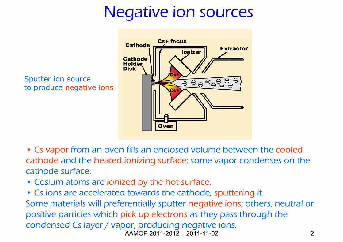
• Cs vapor from an oven fills an enclosed volume between the cooledcathode and the heated ionizing surface; some vapor condenses on thecathode surface. • Cesium atoms are ionized by the hot surface. • Cs ions are accelerated towards the cathode, sputtering it. Some materials will preferentially sputter negative ions; others, neutral orpositive particles which pick up electrons as they pass through thecondensed Cs layer / vapor, producing negative ions.
Sputter ion sourceto produce negative ions
Negative ion sources
AAMOP 2011-2012 2011-11-02 3
Plasma ion source
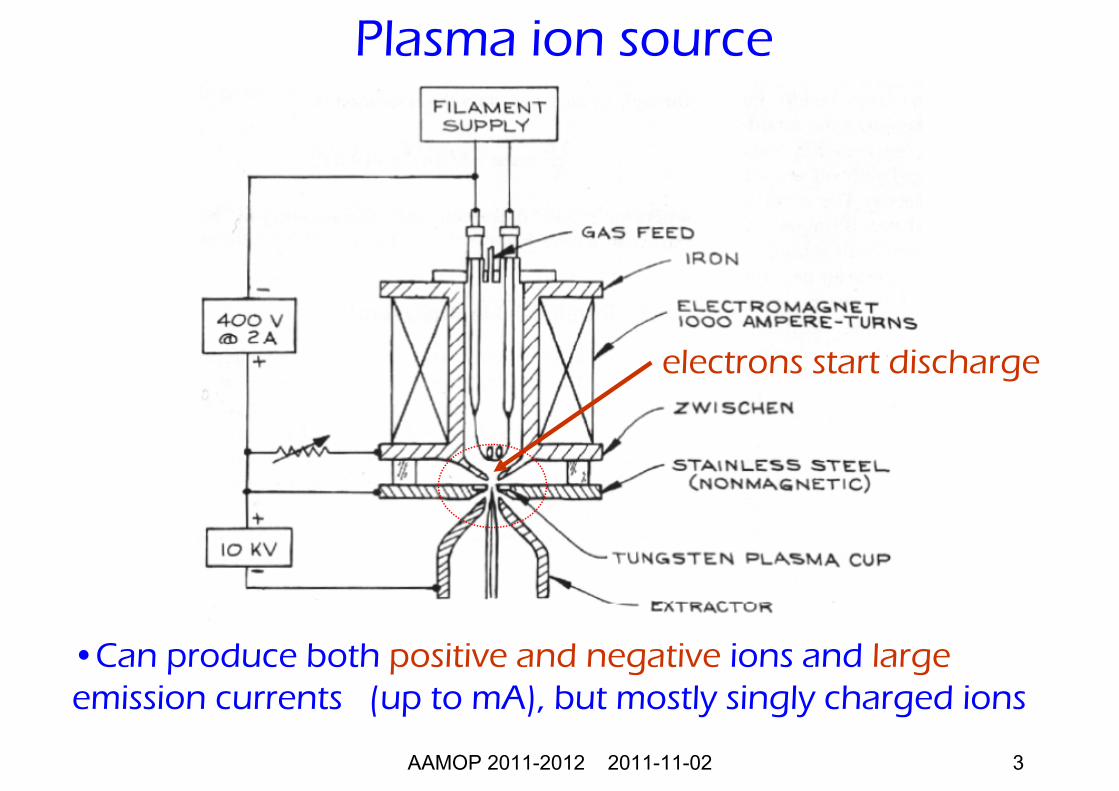
•Can produce both positive and negative ions and largeemission currents (up to mA), but mostly singly charged ions
electrons start discharge
AAMOP 2011-2012 2011-11-02 4
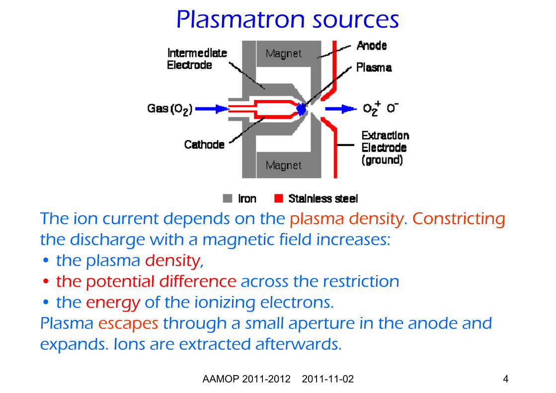
The ion current depends on the plasma density. Constrictingthe discharge with a magnetic field increases: • the plasma density,• the potential difference across the restriction • the energy of the ionizing electrons. Plasma escapes through a small aperture in the anode and expands. Ions are extracted afterwards.
Plasmatron sources
AAMOP 2011-2012 2011-11-02 5
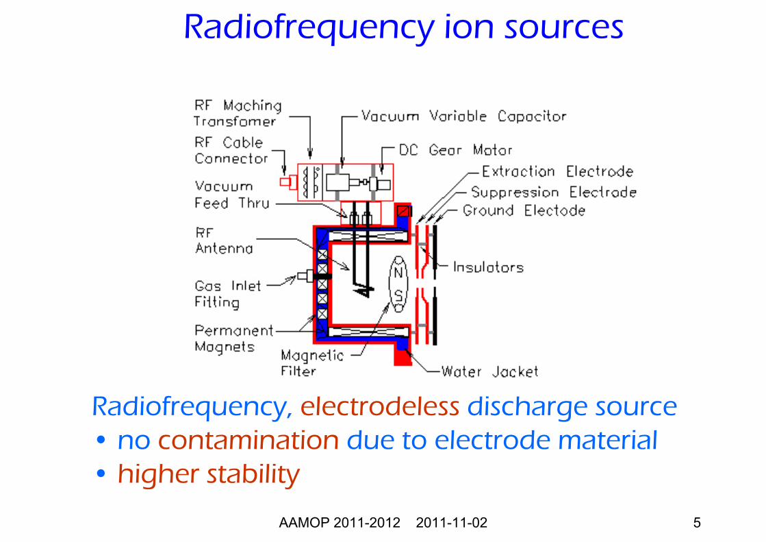
Radiofrequency, electrodeless discharge source• no contamination due to electrode material• higher stability
Radiofrequency ion sources
AAMOP 2011-2012 2011-11-02 6
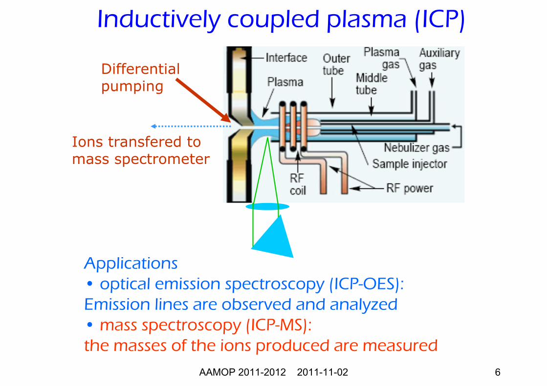
Inductively coupled plasma (ICP)
Applications• optical emission spectroscopy (ICP-OES):Emission lines are observed and analyzed• mass spectroscopy (ICP-MS):the masses of the ions produced are measured
Differentialpumping
Ions transfered tomass spectrometer
AAMOP 2011-2012 2011-11-02 7
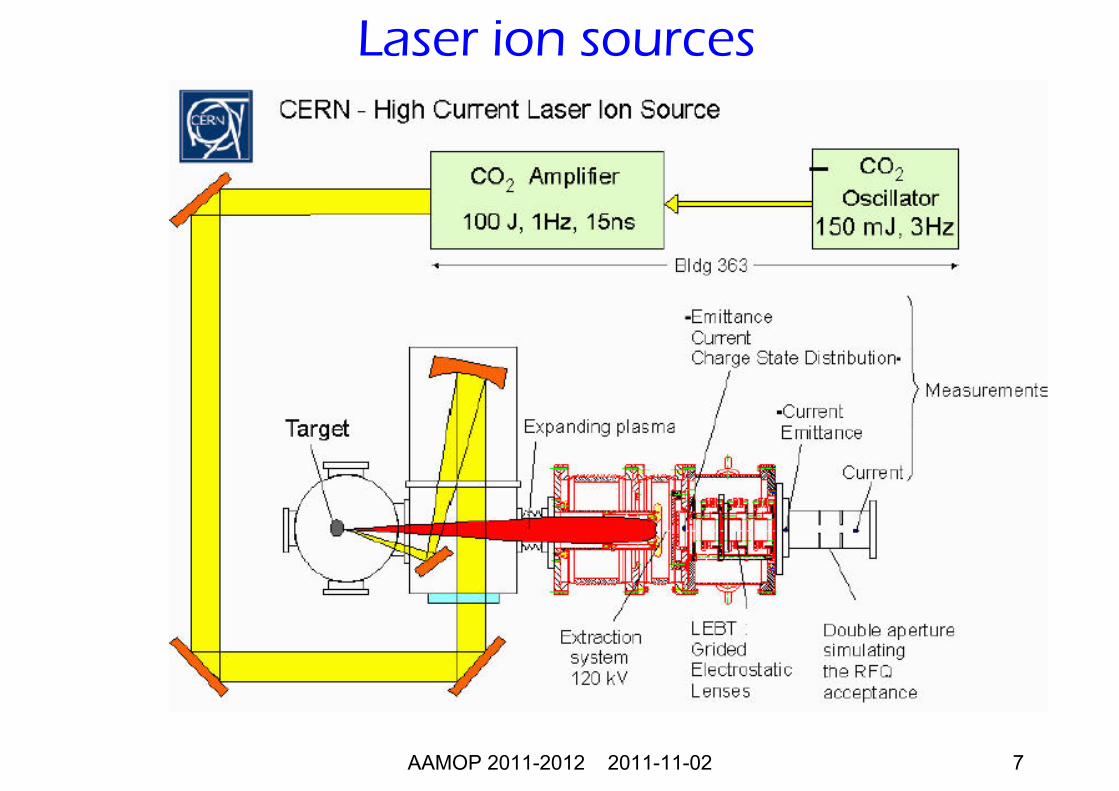
Laser ion sources
AAMOP 2011-2012 2011-11-02 8
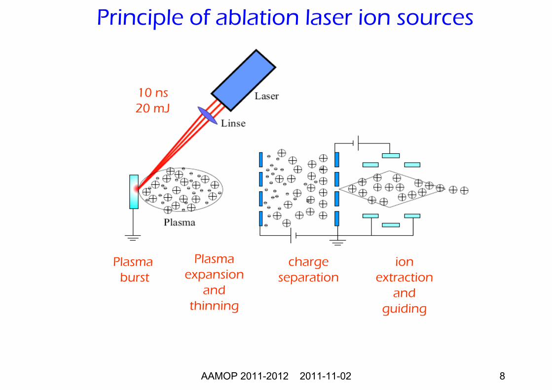
Principle of ablation laser ion sources
Plasma burst
Plasma expansion
and thinning
chargeseparation
ionextraction
and guiding
10 ns20 mJ
AAMOP 2011-2012 2011-11-02 9
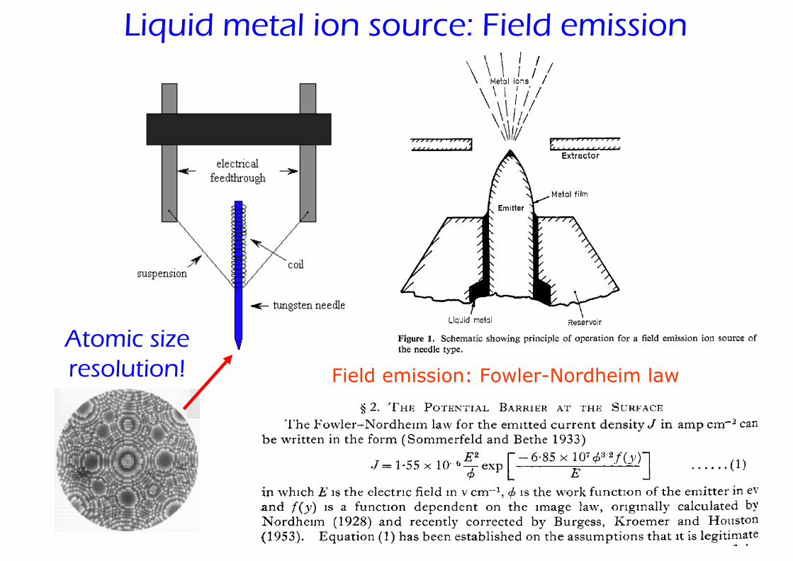
Liquid metal ion source: Field emission
Field emission: Fowler-Nordheim law
Atomic size resolution!
AAMOP 2011-2012 2011-11-02 10
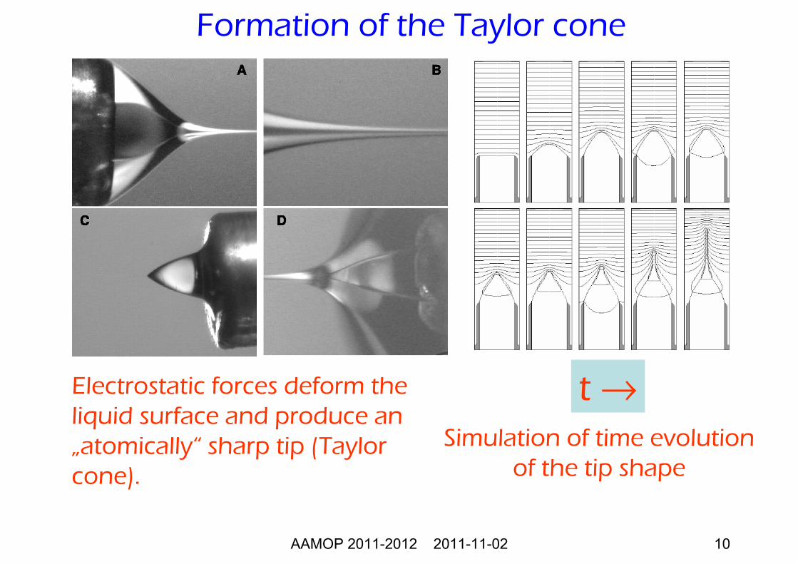
Formation of the Taylor cone
Electrostatic forces deform the liquid surface and produce an „atomically“ sharp tip (Taylor cone).
Simulation of time evolutionof the tip shape
t →
AAMOP 2011-2012 2011-11-02 11
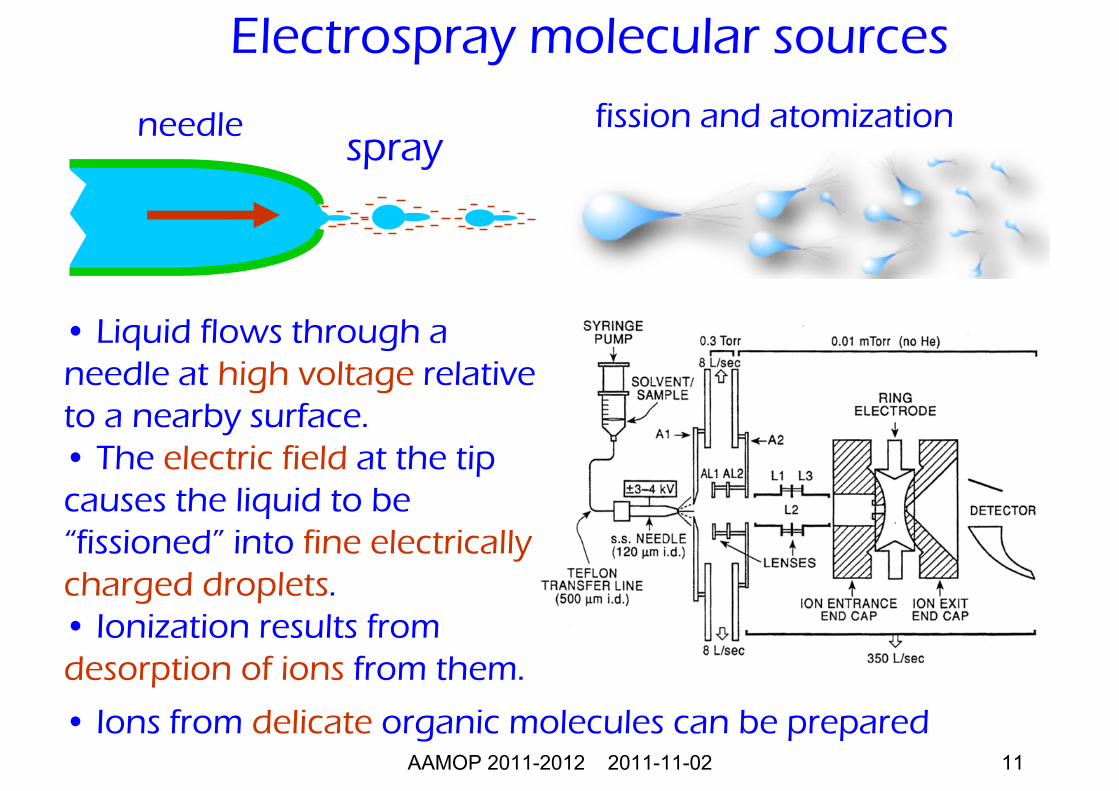
Electrospray molecular sources
• Liquid flows through a needle at high voltage relative to a nearby surface.• The electric field at the tip causes the liquid to be “fissioned” into fine electrically charged droplets.• Ionization results from desorption of ions from them.
needlespray
fission and atomization
• Ions from delicate organic molecules can be prepared
AAMOP 2011-2012 2011-11-02 12
Motivation: Atomic physics in very strong fields
Methods of ionization
Sources of highly charged ions:•Electron cyclotron resonance ions sources (ECRIS)•Electron beam ion sources (EBIS)•Electron beam ion traps (EBIT)
Sources of highly charged ions
AAMOP 2011-2012 2011-11-02 13
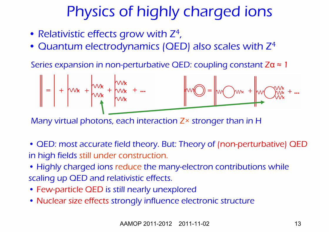
Series expansion in non-perturbative QED: coupling constant Zα ≈ 1
Many virtual photons, each interaction Z× stronger than in H
Physics of highly charged ions
• QED: most accurate field theory. But: Theory of (non-perturbative) QEDin high fields still under construction.• Highly charged ions reduce the many-electron contributions while scaling up QED and relativistic effects.• Few-particle QED is still nearly unexplored• Nuclear size effects strongly influence electronic structure
• Relativistic effects grow with Z4, • Quantum electrodynamics (QED) also scales with Z4
AAMOP 2011-2012 2011-11-02 14
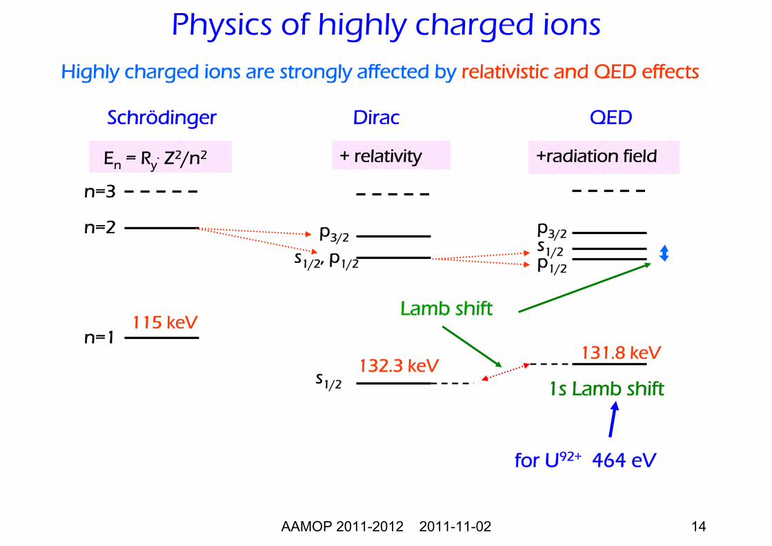
Schrödinger Dirac QED
n=1
p3/2
s1/2, p1/2
n=2
p1/2
s1/2
p3/2
115 keV
132.3 keV131.8 keV
+radiation fieldEn = Ry. Z2/n2
1s Lamb shift
n=3
s1/2
+ relativity
Highly charged ions are strongly affected by relativistic and QED effects
for U92+ 464 eV
Lamb shift
Physics of highly charged ions
AAMOP 2011-2012 2011-11-02 15
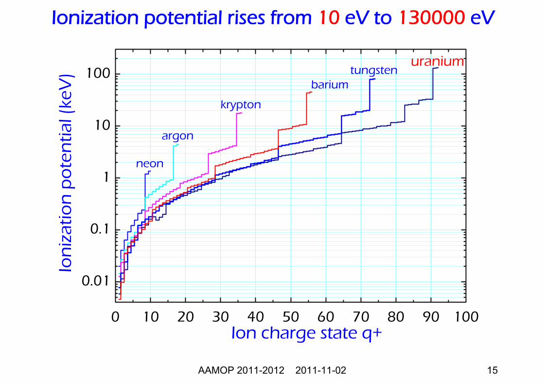
Ionization potential rises from 10 eV to 130000 eV
0 10 20 30 40 50 60 70 80 90 100
0.01
0.1
1
10
100barium
tungsten
krypton
neon
argon
uraniumIo
niz
atio
n p
ote
ntia
l (ke
V)
Ion charge state q+
AAMOP 2011-2012 2011-11-02 16
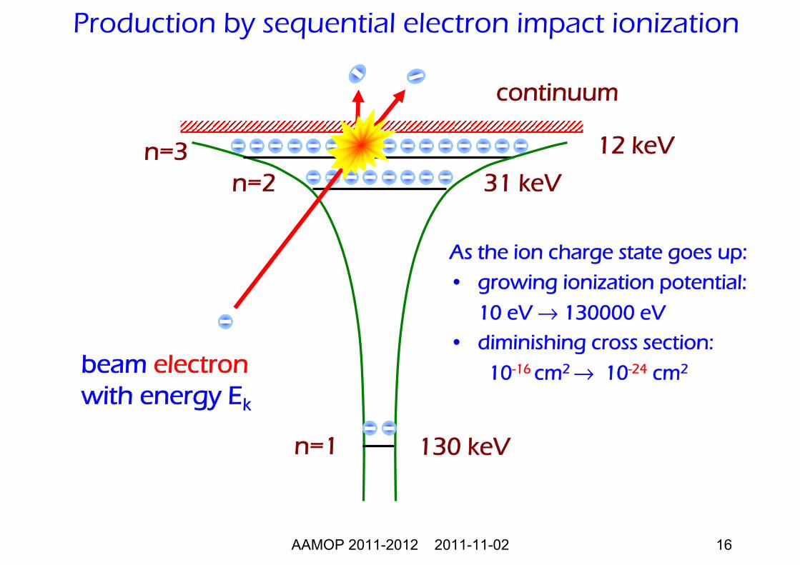
Production by sequential electron impact ionization
As the ion charge state goes up:
• growing ionization potential:
10 eV → 130000 eV• diminishing cross section:
10-16 cm2 → 10-24 cm2
continuum
130 keV
31 keV
12 keV
n=1
n=2 n=3
beam electronwith energy Ek
AAMOP 2011-2012 2011-11-02 17
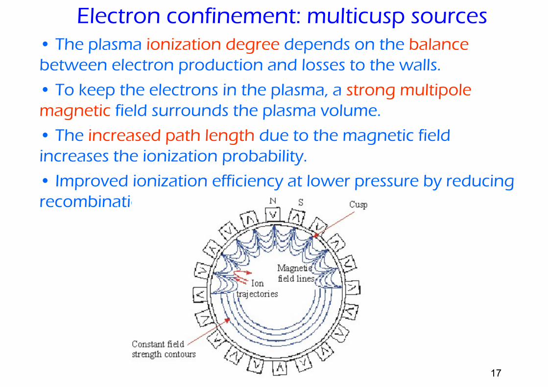
• The plasma ionization degree depends on the balancebetween electron production and losses to the walls.
• To keep the electrons in the plasma, a strong multipole magnetic field surrounds the plasma volume.
• The increased path length due to the magnetic field increases the ionization probability.
• Improved ionization efficiency at lower pressure by reducing recombination.
Electron confinement: multicusp sources
AAMOP 2011-2012 2011-11-02 18
• Electrons rotate in a magnetic field B with frequencyω = e×B/m
and are heated by microwaves at that frequency. • Longitudinal confinement by magnetic fieldconfiguration.• Radial confinement by magnetic multipoles.• High electron temperature: multi-charged ionproduction at densities > 1012 electrons/cm3.• Used on cyclotrons and synchrotrons for theproduction of HCI beams.
Electron cyclotron resonance ion source
AAMOP 2011-2012 2011-11-02 19
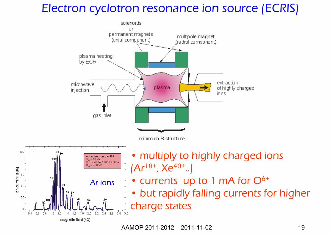
Ar ions
• multiply to highly charged ions (Ar18+, Xe40+..) • currents up to 1 mA for O6+
• but rapidly falling currents for higher charge states
Electron cyclotron resonance ion source (ECRIS)
AAMOP 2011-2012 2011-11-02 20
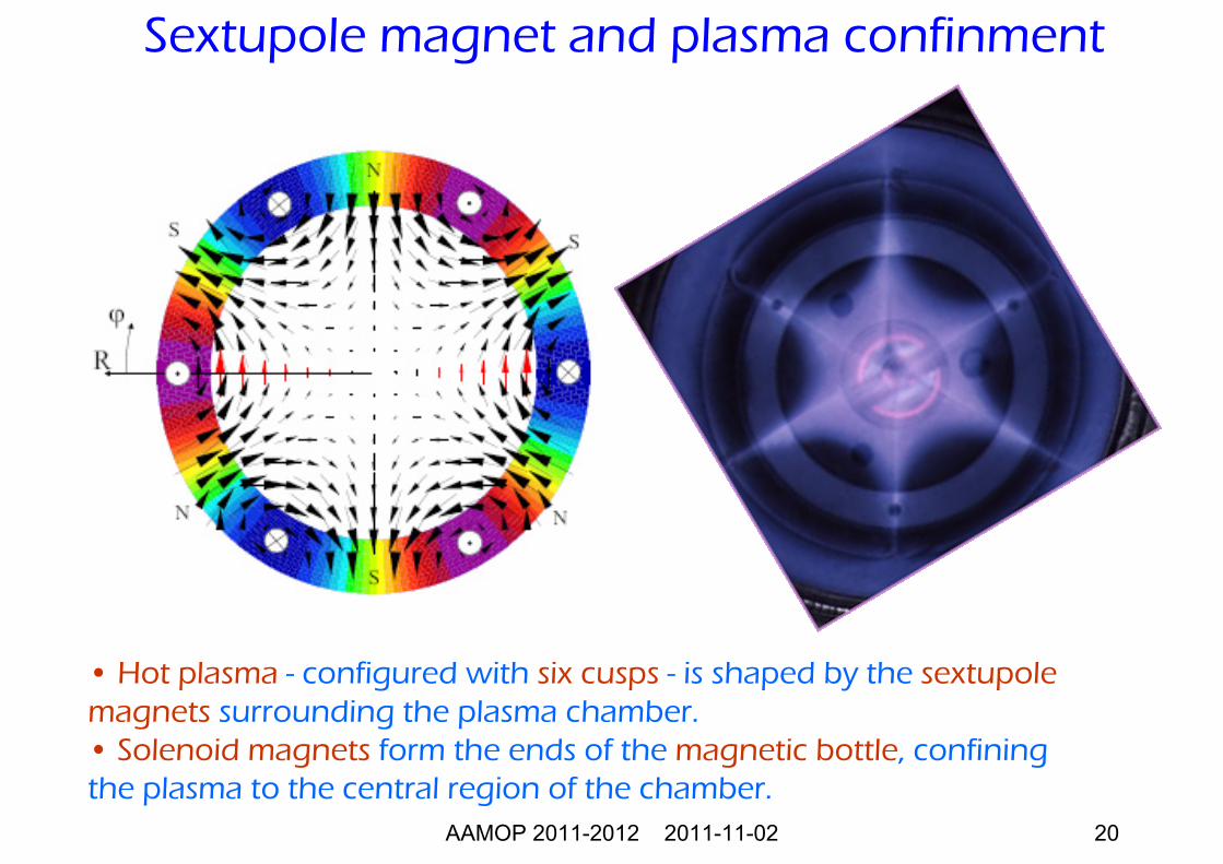
• Hot plasma - configured with six cusps - is shaped by the sextupolemagnets surrounding the plasma chamber. • Solenoid magnets form the ends of the magnetic bottle, confiningthe plasma to the central region of the chamber.
Sextupole magnet and plasma confinment
AAMOP 2011-2012 2011-11-02 21
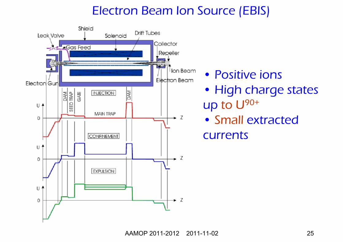
• An intense electron beam interacts with ions trapped in an electrostatic well. • Ions are confined radially by the space charge in the electron beam and axially by positive electrodes. • The ions can be investigated within the trap or expelled by lowering the potential of one end electrode.
Electron beam ion source (EBIS)
AAMOP 2011-2012 2011-11-02 22
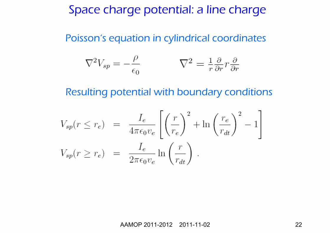
Poisson‘s equation in cylindrical coordinates
Resulting potential with boundary conditions
Space charge potential: a line charge
AAMOP 2011-2012 2011-11-02 23
1000 2000 30000
20
40
60
80
100
120
140
center drift tube radiusspace charge potential
electron density
Spac
e ch
arg
e p
ote
ntia
l (V
)
Distance from axis (μm)
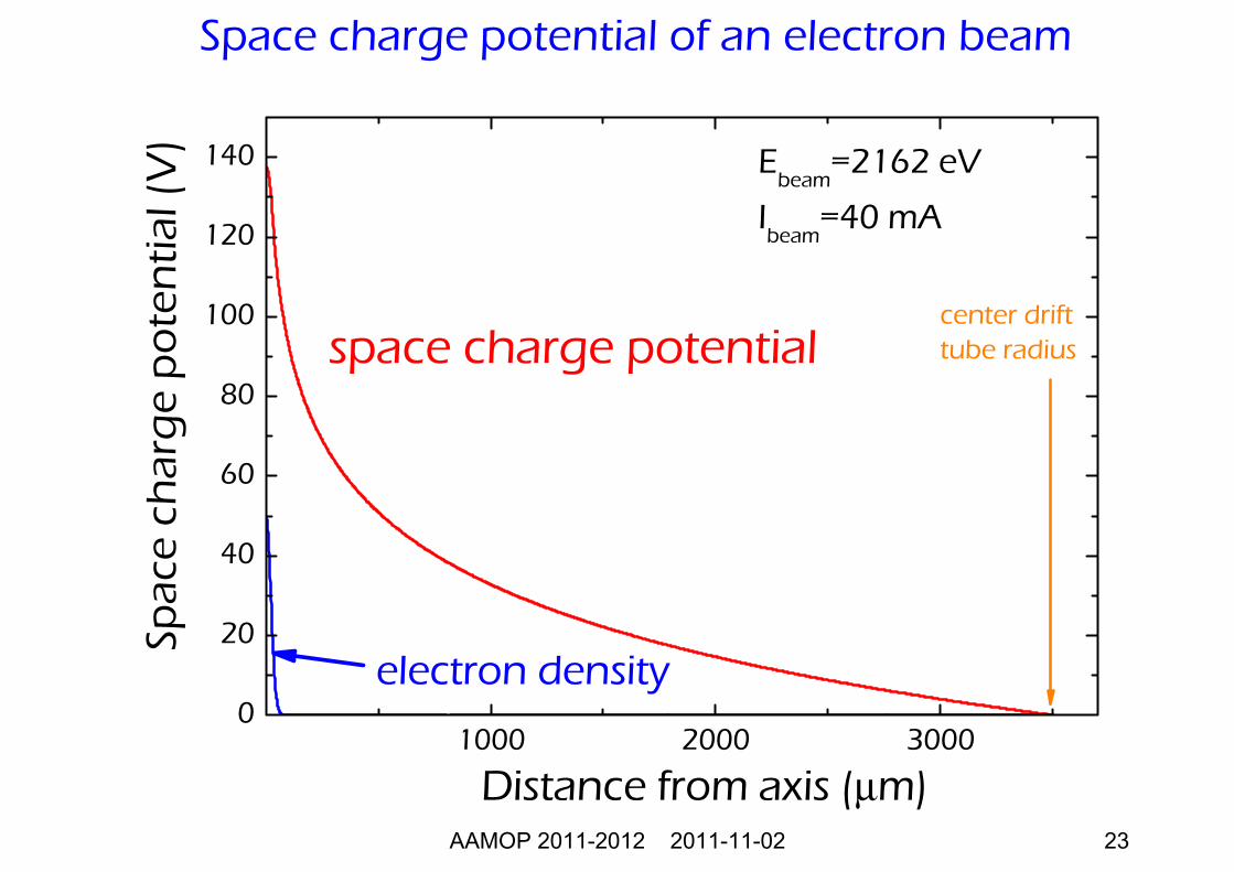
Ebeam
=2162 eV
Ibeam
=40 mA
Space charge potential of an electron beam
AAMOP 2011-2012 2011-11-02 24
0.1 1 10 100 1000
0
20
40
60
80
100
120
140
center drift tube radius
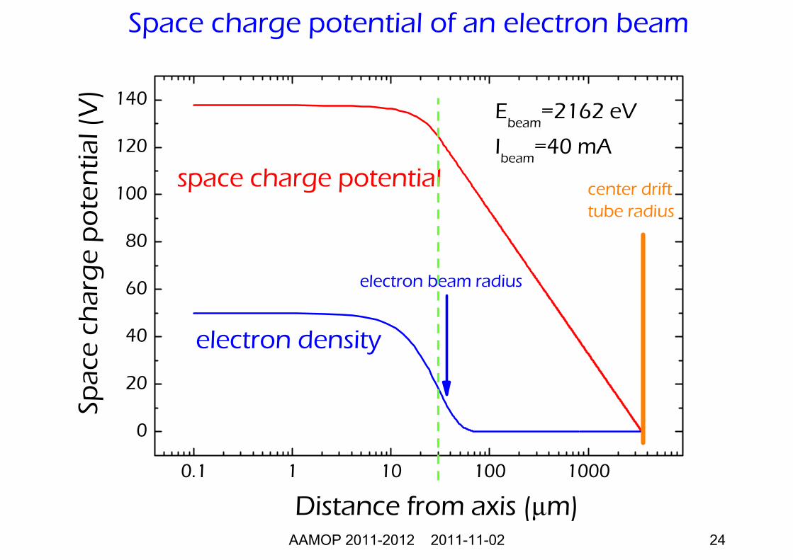
electron beam radius
space charge potential
electron density
Spac
e ch
arg
e p
ote
ntia
l (V
)
Distance from axis (μm)
Ebeam
=2162 eV
Ibeam
=40 mA
Space charge potential of an electron beam
AAMOP 2011-2012 2011-11-02 25
Electron Beam Ion Source (EBIS)
• Positive ions • High charge states up to U90+
• Small extracted currents
AAMOP 2011-2012 2011-11-02 26
• As electrons collide with the ions in the beam, they strip off electrons until the energy required to remove the next electron is higher than the beamenergy.
• The original LLNL EBIT (1986) used an electronbeam energy of about 30 keV to make neon-likeuranium (U82+).
• SuperEBIT achieved an electron beam energy of 200 keV, enough to make bare uranium (U92+).
The electron beam ion trap (EBIT)
AAMOP 2011-2012 2011-11-02 27
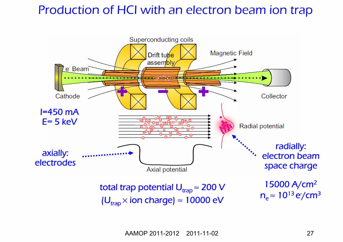
Production of HCI with an electron beam ion trap
radially: electron beamspace charge
total trap potential Utrap ≈ 200 V
(Utrap × ion charge) ≈ 10000 eV
15000 A/cm2
ne ≈ 1013 e-/cm3
axially: electrodes
I=450 mAE= 5 keV
AAMOP 2011-2012 2011-11-02 28
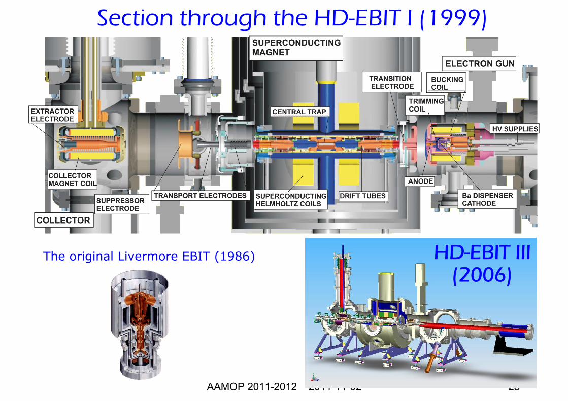
Section through the HD-EBIT I (1999)
HD-EBIT III(2006)
The original Livermore EBIT (1986)
AAMOP 2011-2012 2011-11-02 29
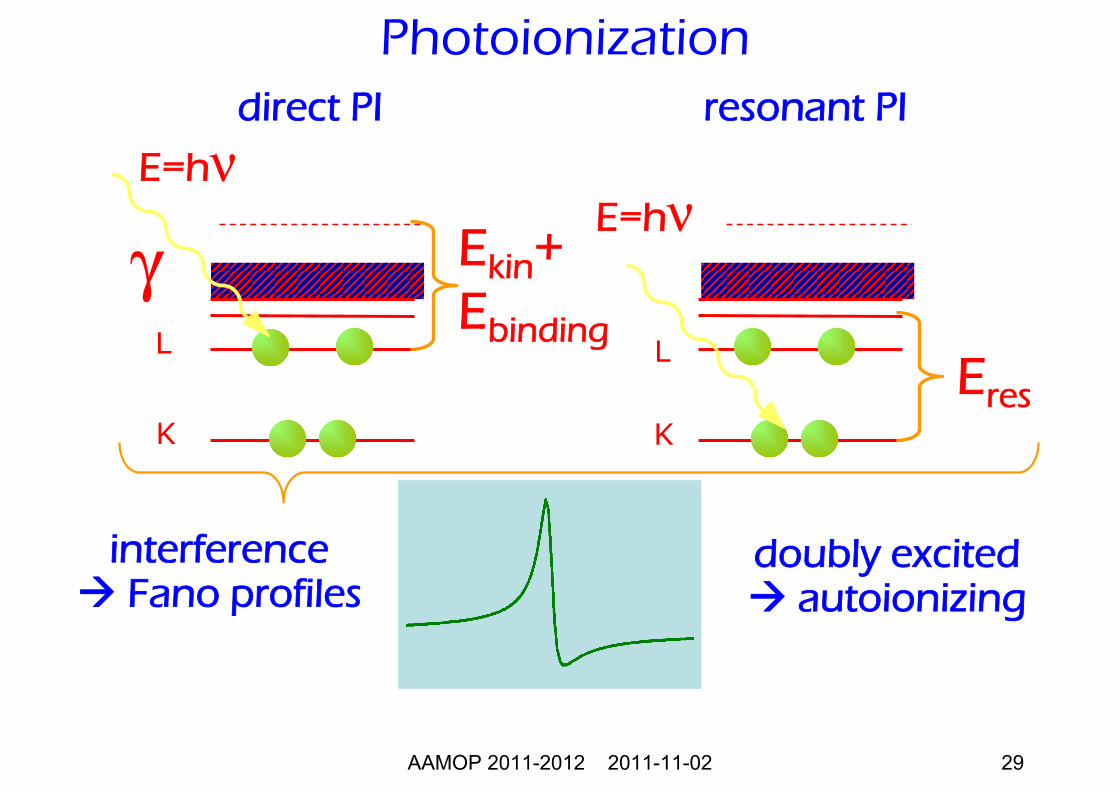
direct PI
E=hνEkin+Ebinding
resonant PI
K
L
E=hν
Eres
doubly excitedautoionizing
γ
interferenceFano profiles
K
L
Photoionization
AAMOP 2011-2012 2011-11-02 30
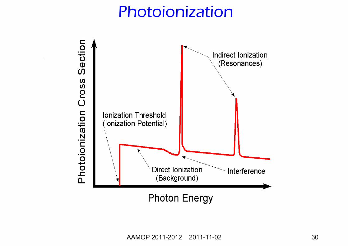
Photoionization
AAMOP 2011-2012 2011-11-02 31
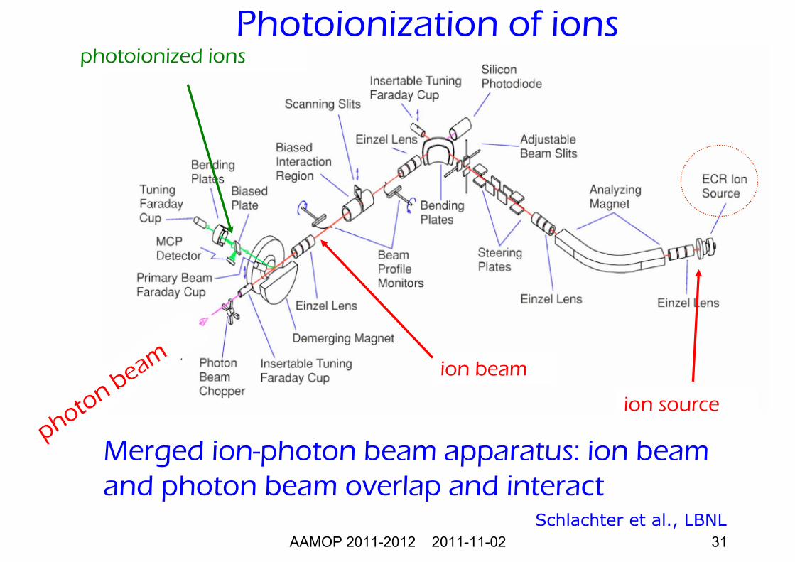
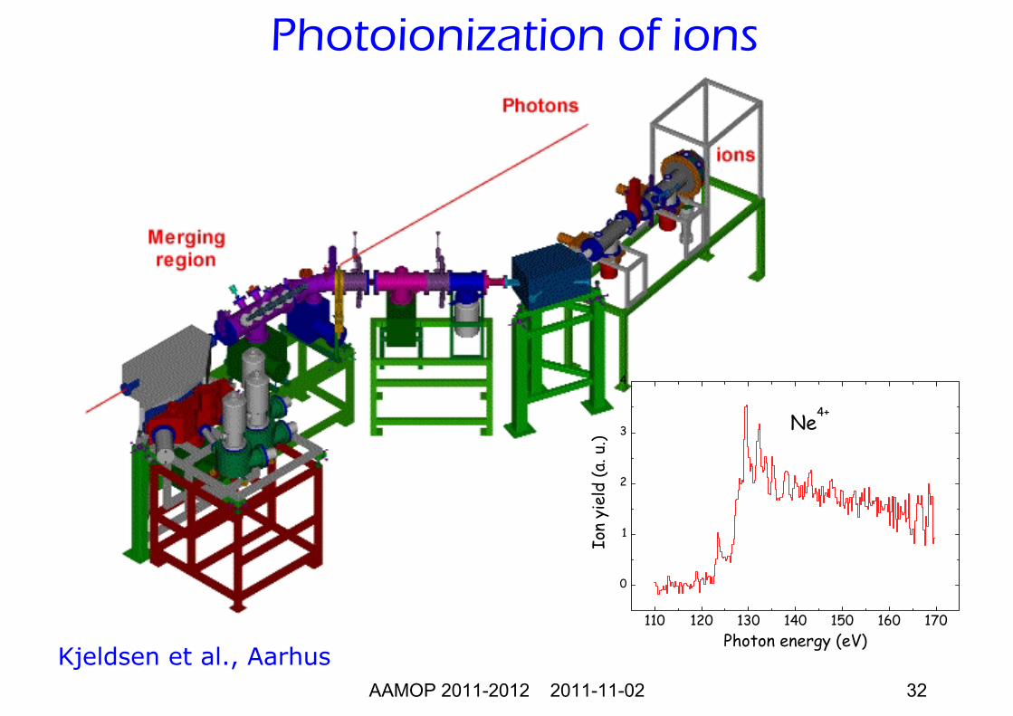
Photoionization of ions
Merged ion-photon beam apparatus: ion beamand photon beam overlap and interact
Schlachter et al., LBNL
photon beam ion beam
photoionized ions
ion source
AAMOP 2011-2012 2011-11-02 32
110 120 130 140 150 160 170
0
1
2
3
4
Ion
yiel
d (a
. u.)
Photon energy (eV)
Ne4+
Photoionization of ions
Kjeldsen et al., Aarhus
AAMOP 2011-2012 2011-11-02 33
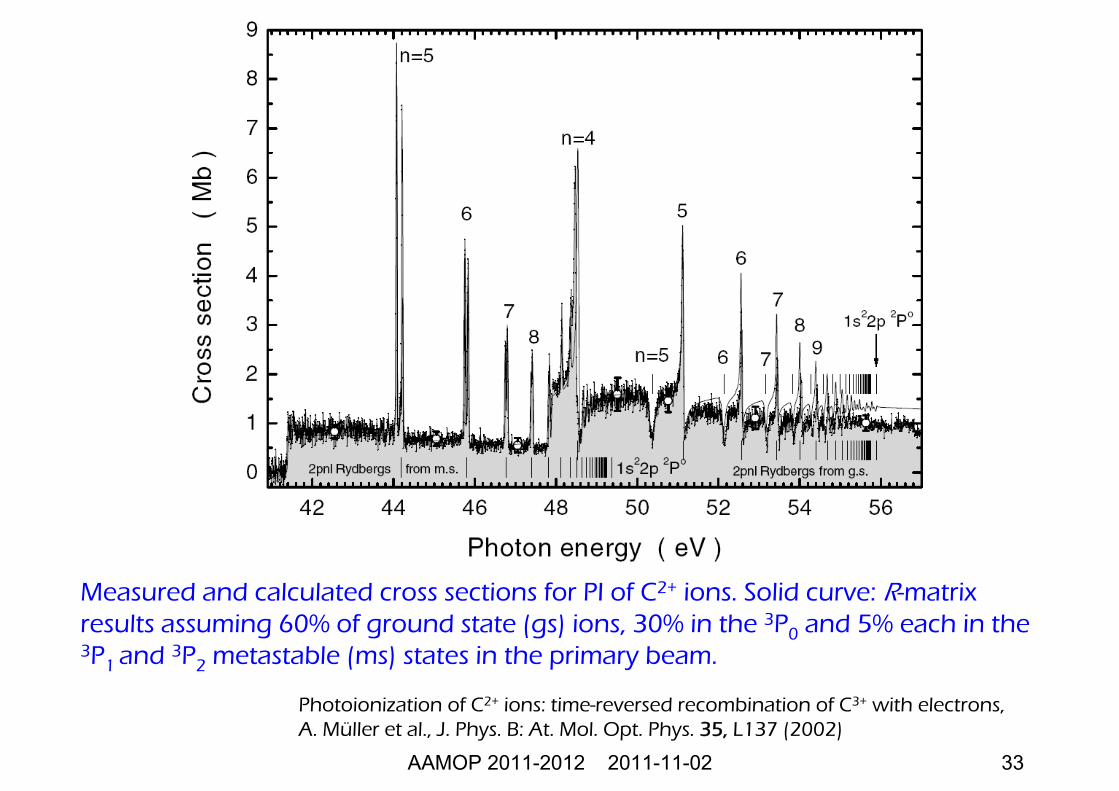
Measured and calculated cross sections for PI of C2+ ions. Solid curve: R-matrix results assuming 60% of ground state (gs) ions, 30% in the 3P0 and 5% each in the 3P1 and 3P2 metastable (ms) states in the primary beam.
Photoionization of C2+ ions: time-reversed recombination of C3+ with electrons, A. Müller et al., J. Phys. B: At. Mol. Opt. Phys. 35, L137 (2002)
AAMOP 2011-2012 2011-11-02 34
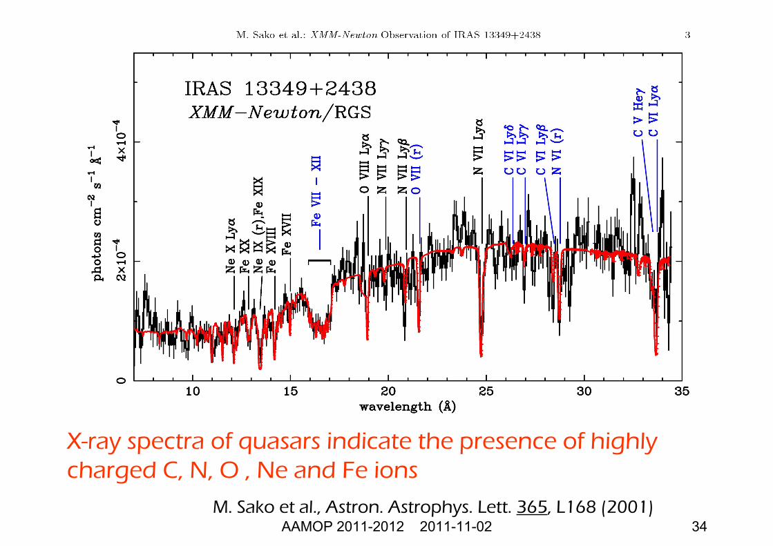
X-ray spectra of quasars indicate the presence of highly charged C, N, O , Ne and Fe ions
M. Sako et al., Astron. Astrophys. Lett. 365, L168 (2001)
AAMOP 2011-2012 2011-11-02 35
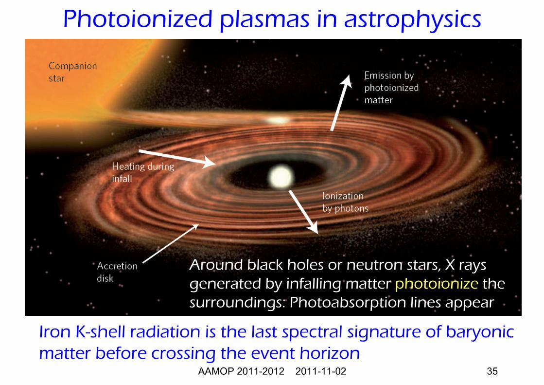
Around black holes or neutron stars, X rays generated by infalling matter photoionize the surroundings: Photoabsorption lines appear
Iron K-shell radiation is the last spectral signature of baryonicmatter before crossing the event horizon
Photoionized plasmas in astrophysics
AAMOP 2011-2012 2011-11-02 36
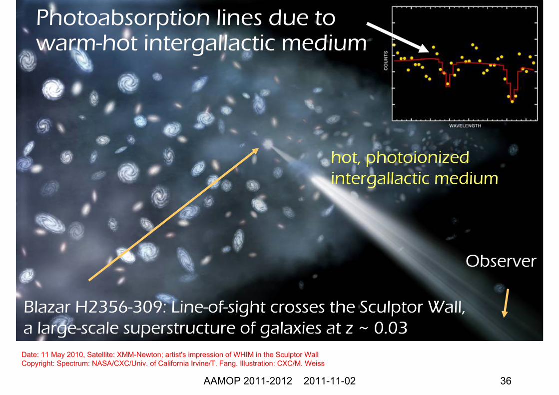
Date: 11 May 2010, Satellite: XMM-Newton; artist's impression of WHIM in the Sculptor WallCopyright: Spectrum: NASA/CXC/Univ. of California Irvine/T. Fang. Illustration: CXC/M. Weiss
Blazar H2356-309: Line-of-sight crosses the Sculptor Wall, a large-scale superstructure of galaxies at z ~ 0.03
Observer
Photoabsorption lines due to warm-hot intergallactic medium
hot, photoionizedintergallactic medium
AAMOP 2011-2012 2011-11-02 37
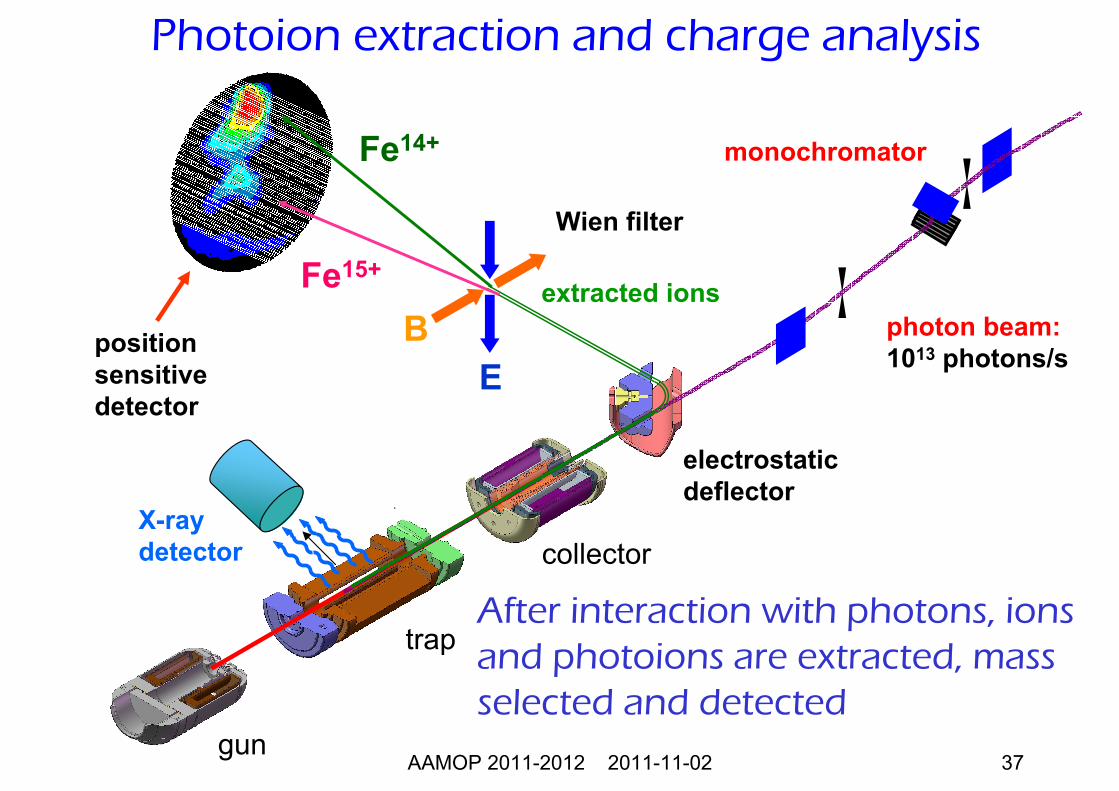
Photoion extraction and charge analysis
After interaction with photons, ionsand photoions are extracted, massselected and detected
electrostaticdeflector
gun
trap
collector
photon beam:1013 photons/s
Wien filter
positionsensitivedetector
Fe14+
Fe15+
BE
monochromator
extracted ions
X-raydetector
AAMOP 2011-2012 2011-11-02 38
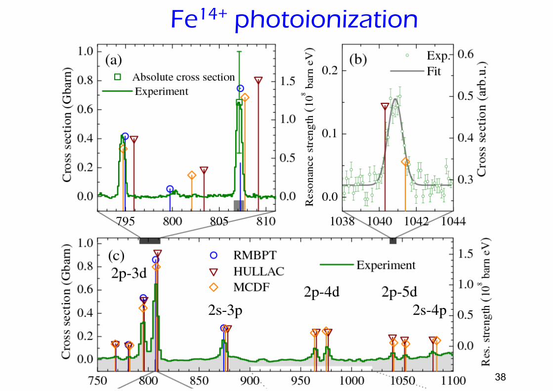
Fe14+ photoionization
AAMOP 2011-2012 2011-11-02 39
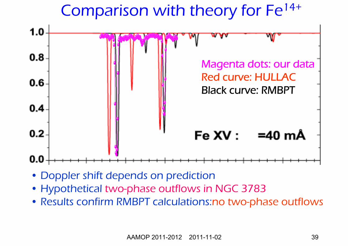
Comparison with theory for Fe14+
• Doppler shift depends on prediction• Hypothetical two-phase outflows in NGC 3783• Results confirm RMBPT calculations:no two-phase outflows
Magenta dots: our dataRed curve: HULLACBlack curve: RMBPT
AAMOP 2011-2012 2011-11-02 40
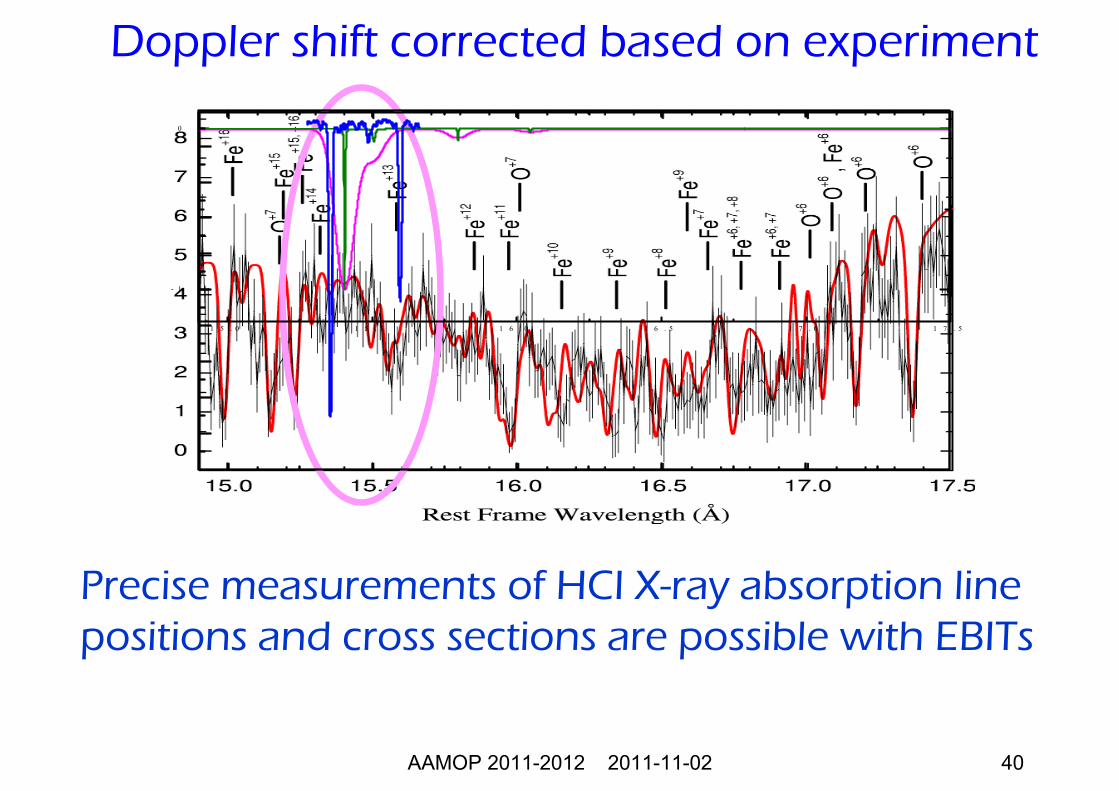
Doppler shift corrected based on experiment
1 5 . 0 1 5 . 5 1 6 . 0 1 6 . 5 1 7 . 0 1 7 . 5
- 1
0
Precise measurements of HCI X-ray absorption line positions and cross sections are possible with EBITs
AAMOP 2011-2012 2011-11-02 41
• Acceleration schemes for ions• Electrostatic accelerators• RF accelerators
Accelerators
AAMOP 2011-2012 2011-11-02 42
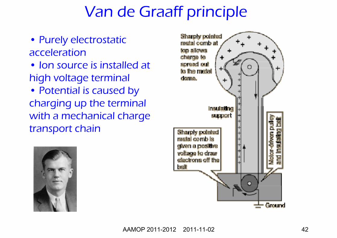
Van de Graaff principle
• Purely electrostaticacceleration• Ion source is installed at high voltage terminal• Potential is caused bycharging up the terminalwith a mechanical chargetransport chain
AAMOP 2011-2012 2011-11-02 43
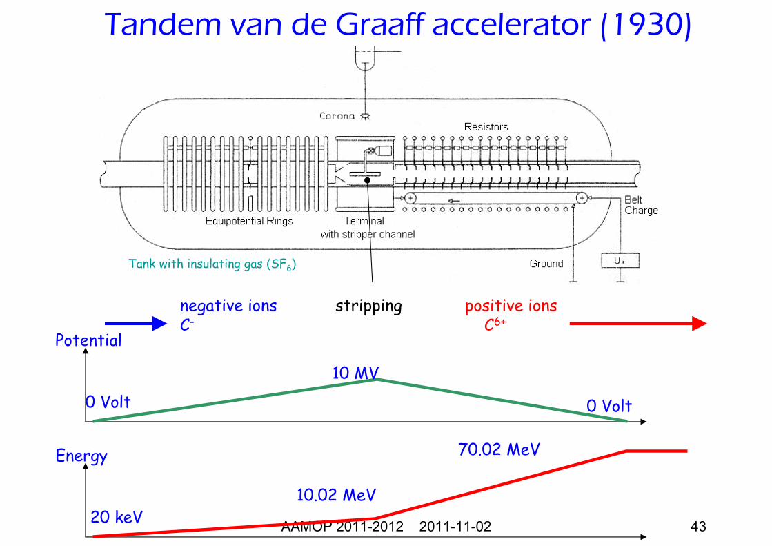
Potential
0 Volt 0 Volt
10 MV
Energy
20 keV10.02 MeV
70.02 MeV
negative ionsC-
stripping positive ionsC6+
Tank with insulating gas (SF6)
Tandem van de Graaff accelerator (1930)
AAMOP 2011-2012 2011-11-02 44
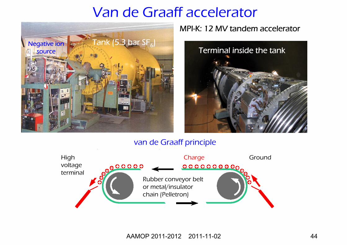
MPI-K: 12 MV tandem accelerator
High voltageterminal
GroundCharge
Rubber conveyor beltor metal/insulatorchain (Pelletron)
van de Graaff principle
Tank (5.3 bar SF6)Terminal inside the tank
Negative ionsource
Van de Graaff accelerator
AAMOP 2011-2012 2011-11-02 45
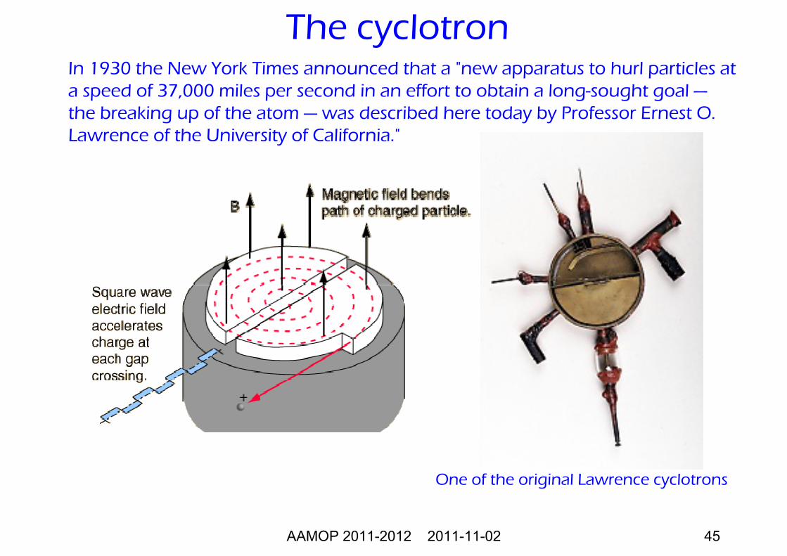
In 1930 the New York Times announced that a "new apparatus to hurl particles at a speed of 37,000 miles per second in an effort to obtain a long-sought goal —the breaking up of the atom — was described here today by Professor Ernest O. Lawrence of the University of California."
The cyclotron
One of the original Lawrence cyclotrons
AAMOP 2011-2012 2011-11-02 46
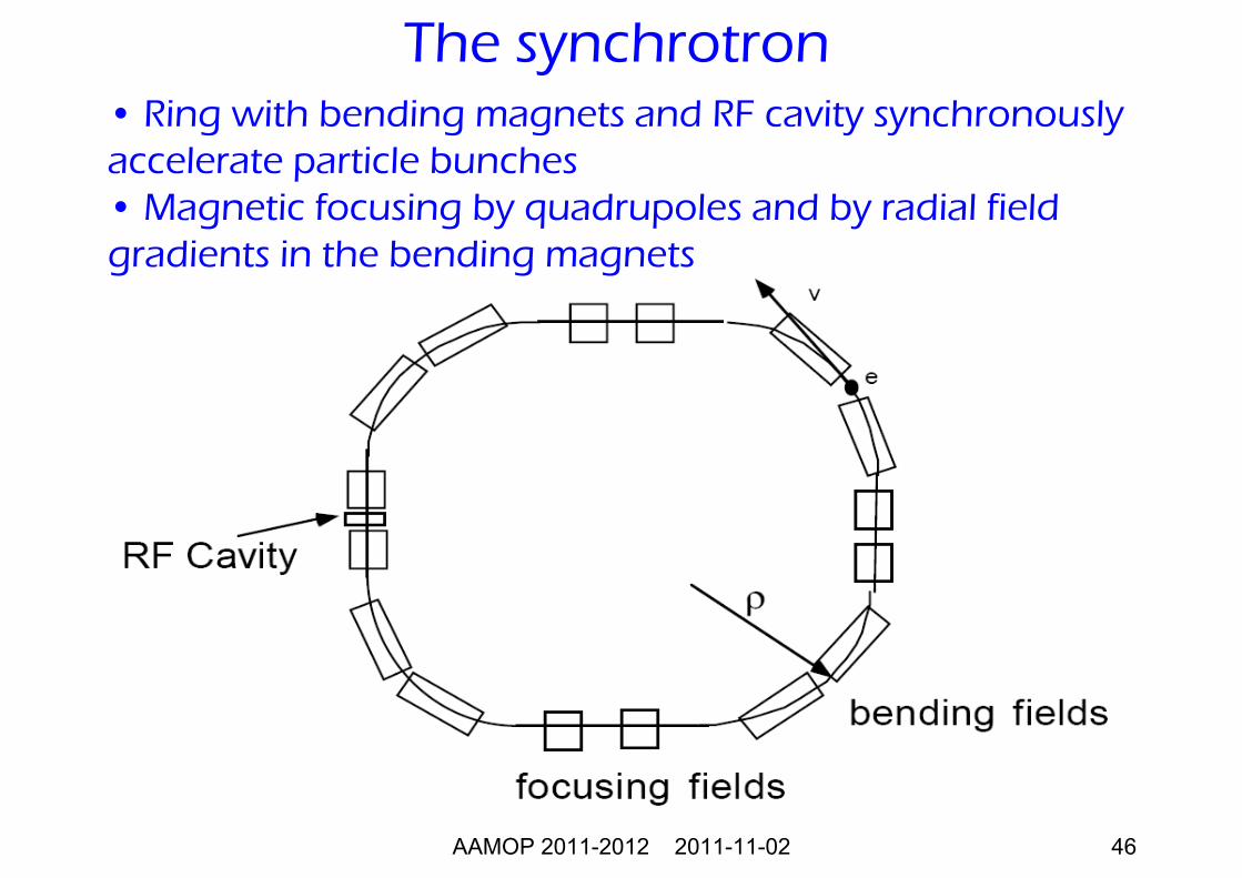
The synchrotron• Ring with bending magnets and RF cavity synchronouslyaccelerate particle bunches• Magnetic focusing by quadrupoles and by radial fieldgradients in the bending magnets
AAMOP 2011-2012 2011-11-02 47
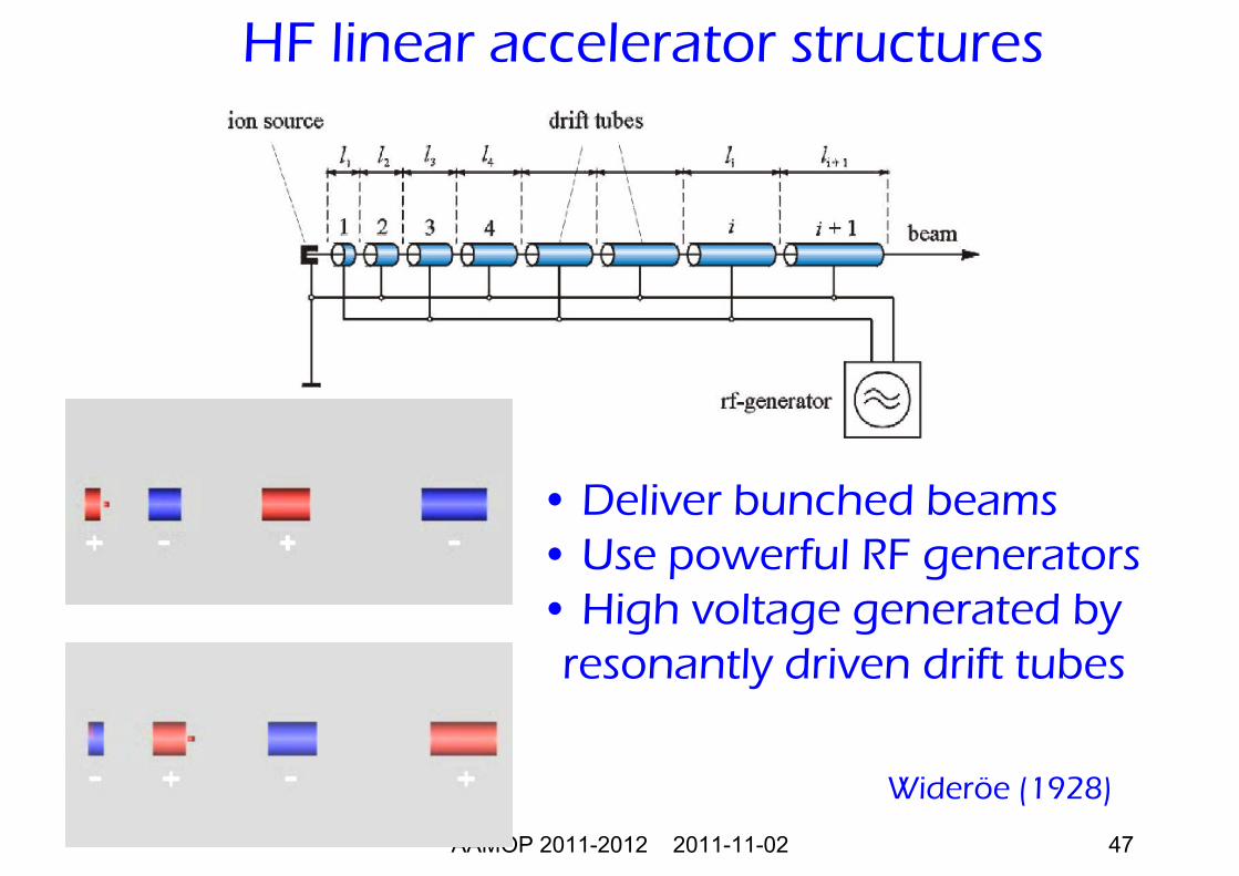
HF linear accelerator structures
Wideröe (1928)
• Deliver bunched beams• Use powerful RF generators• High voltage generated by
resonantly driven drift tubes
AAMOP 2011-2012 2011-11-02 48
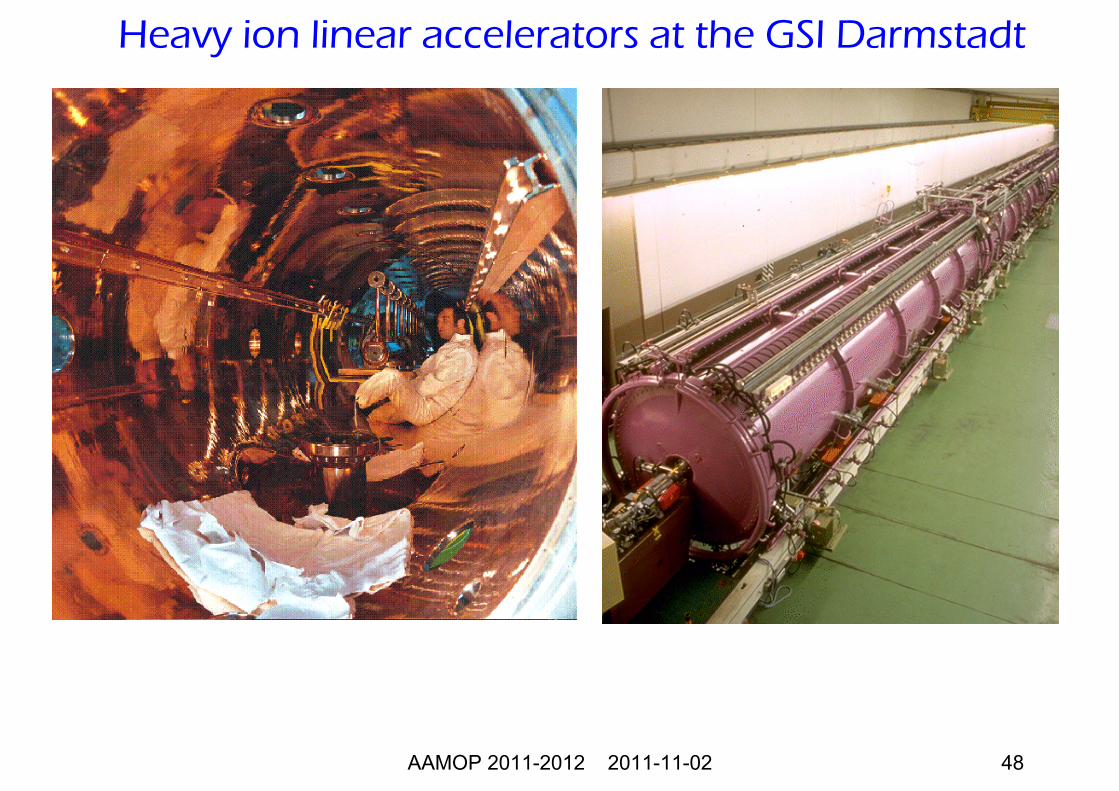
Heavy ion linear accelerators at the GSI Darmstadt
AAMOP 2011-2012 2011-11-02 49
++
-
-
GSI
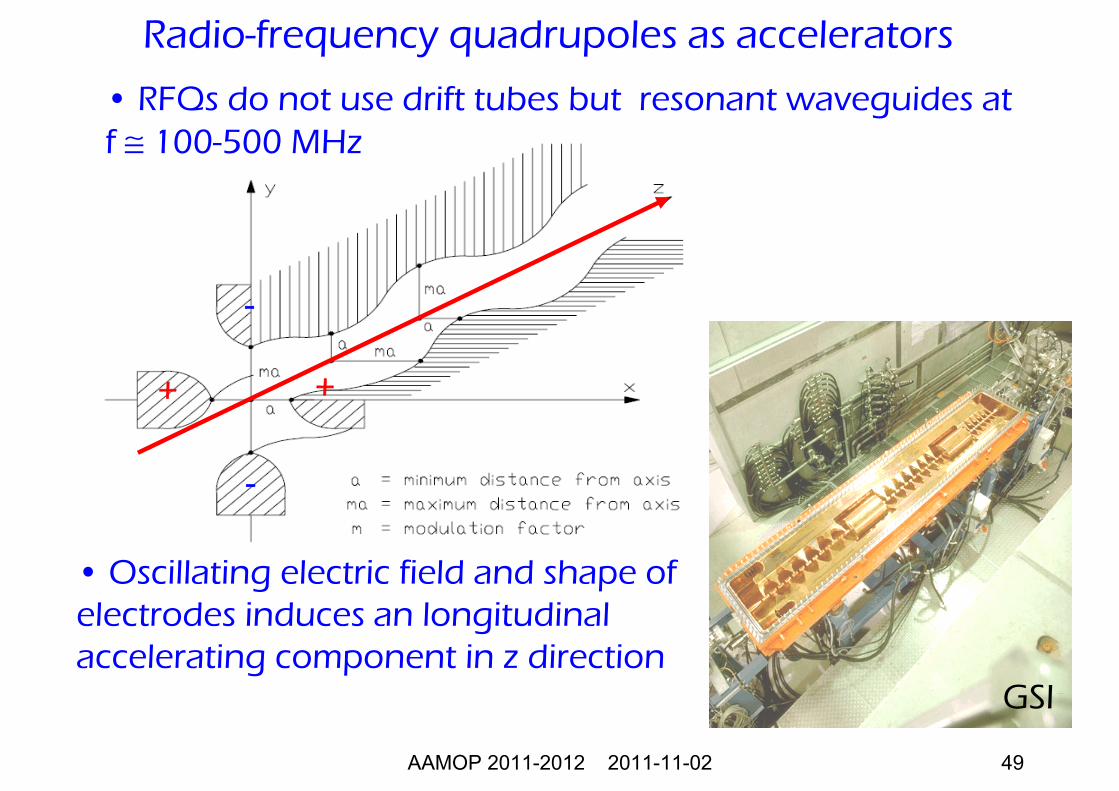
• RFQs do not use drift tubes but resonant waveguides at f ≅ 100-500 MHz
• Oscillating electric field and shape of electrodes induces an longitudinalaccelerating component in z direction
Radio-frequency quadrupoles as accelerators
AAMOP 2011-2012 2011-11-02 50
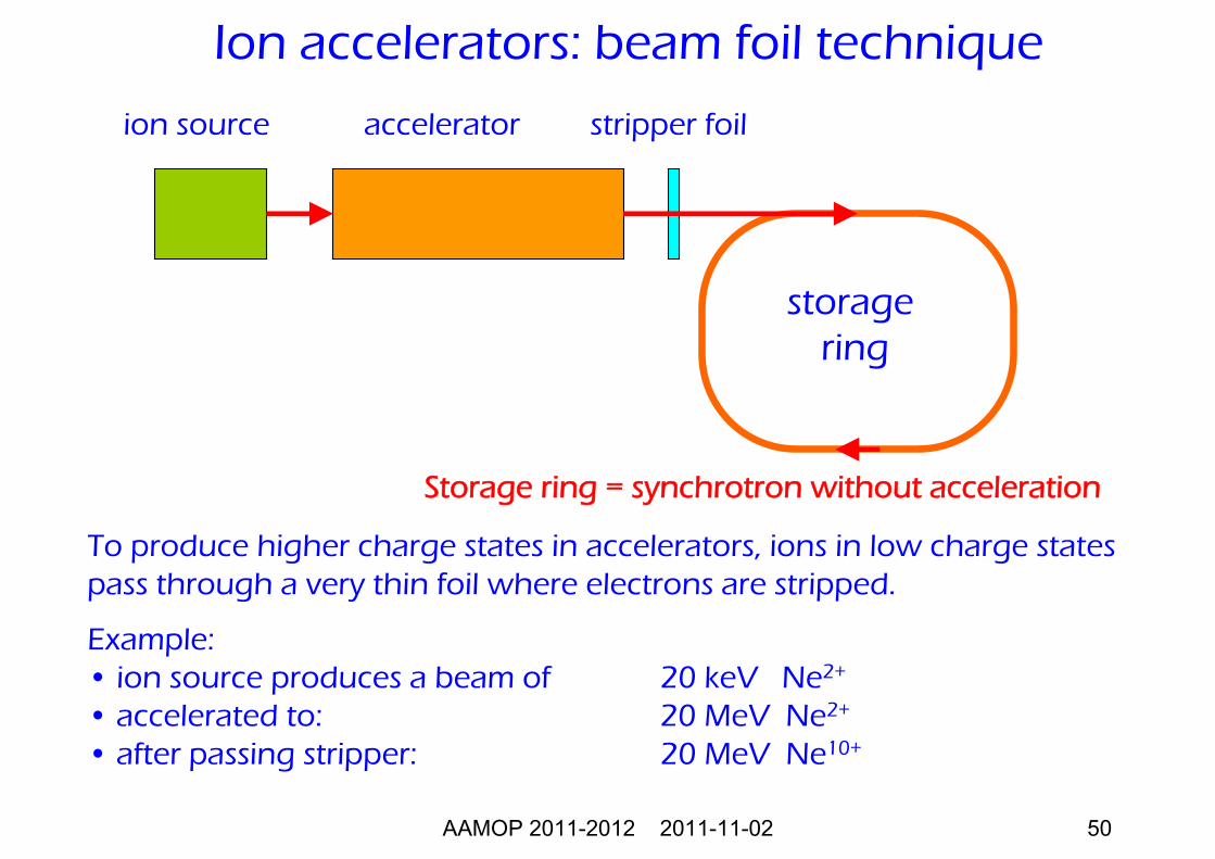
Ion accelerators: beam foil technique
To produce higher charge states in accelerators, ions in low charge statespass through a very thin foil where electrons are stripped.
Example:• ion source produces a beam of 20 keV Ne2+
• accelerated to: 20 MeV Ne2+
• after passing stripper: 20 MeV Ne10+
ion source accelerator stripper foil
storagering
Storage ring = synchrotron without acceleration
AAMOP 2011-2012 2011-11-02 51
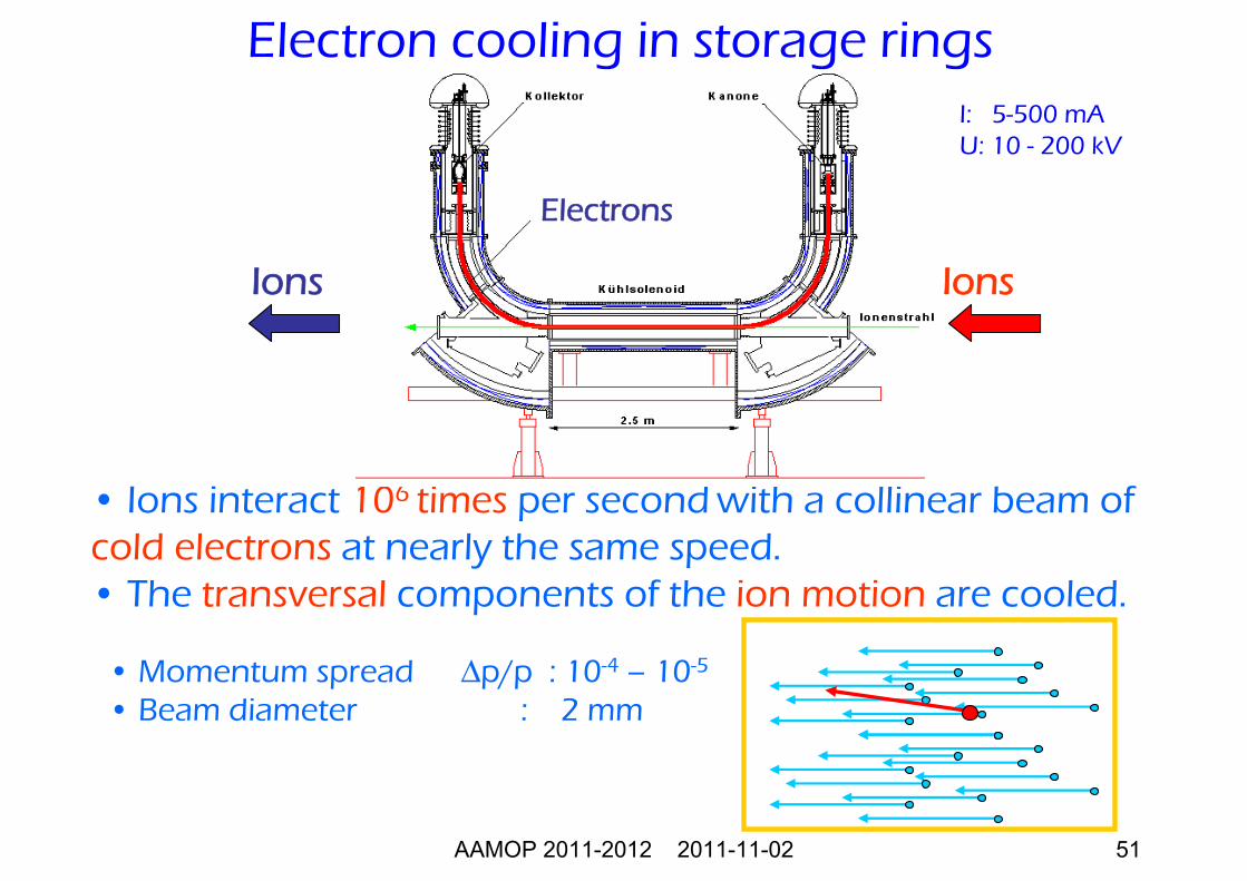
• Ions interact 106 times per second with a collinear beam of cold electrons at nearly the same speed. • The transversal components of the ion motion are cooled.
IonsIons
I: 5-500 mAU: 10 - 200 kV
Electrons
• Momentum spread Δp/p : 10-4 – 10-5
• Beam diameter : 2 mm
Electron cooling in storage rings