iot with the raspberry-pi3 - archivo digital...
TRANSCRIPT

E T S I S . T e l e c o m u n i c a c i ó n – U n i v e r s i d a d P o l i t é c n i c a d e M a d r i d
2018
IoT WITH THE RASPBERRY-PI3
Sergio Esquembri
Dpto de Telemática y Electrónica Universidad Politécnica de Madrid

Page 1 of 22

Page 2 of 22
Acknoledgements
This document is based on a previous work using RPI Model B of my colleagues Dr. Mariano Ruiz, Dr. Eduardo Barrera, and Dr. Francisco Javier Jímenez from the Department of Telematics and Electronics Engineering of the Technical University of Madrid.
IoT WITH THE RASPBERRY-PI3 by Sergio Esquembri is licensed under a Creative Commons Attribution-ShareAlike 4.0 International License.

Page 3 of 22
Table of contents
1 SCOPE ........................................................................................................................................ 5
1.1 Document Overview .............................................................................................................. 5
1.2 Acronyms .............................................................................................................................. 5
2 REFERENCED DOCUMENTS ......................................................................................................... 6
2.1 Reference documentation. ..................................................................................................... 6
3 OPERATING SYSTEM INSTALLATION ............................................................................................ 7
3.1 Downloading and installing Raspbian. .................................................................................... 7
3.2 Updating Raspbian ............................................................................................................... 10
3.3 Connecting to the Raspberry-Pi using SSH and a graphical X client (Optional). ....................... 10
3.3.1 Xming Software ........................................................................................................................ 10
3.3.2 Moba Xterm Software.............................................................................................................. 13
4 DISPLAYING RASPBERRY-PI MAC ADDRESS ............................................................................... 15
5 CONNECTING RPI TO INTERNET IN THE LABORATORY ................................................................ 16
5.1 Adding proxy configuration .................................................................................................. 16
5.2 Using git with a proxy. .......................................................................................................... 16
6 CONNECTING SENSORS TO THE RASPBERRY-PI .......................................................................... 17
6.1 Introduction ......................................................................................................................... 17
6.2 First steps with Pi GPIO: Raspberry Pi Electronics Starter Kit .................................................. 18
6.3 Programming the Raspberry Pi in C language ........................................................................ 18
6.3.1 Installing Code::Blocks IDE ....................................................................................................... 18
6.3.2 wiringPi. GPIO Interface library ............................................................................................... 19
6.3.3 HIH-6120-021-001 Humidity and Temperature Sensor ........................................................... 20

Page 4 of 22
TABLE OF FIGURES FIG. 1: WIN32 DISK IMAGER ..................................................................................................................................................... 7 FIG. 2: ENABLING SSH COMMAND LINE. ...................................................................................................................................... 8 FIG. 3: ENABLING SSH COMMAND LINE. ...................................................................................................................................... 9 FIG. 4: ENABLING SSH COMMAND LINE. ...................................................................................................................................... 9 FIG. 5: REMOTE ACCESS TO THE RASPBERRY-PI ............................................................................................................................ 10 FIG. 6: XLAUNCH ................................................................................................................................................................... 11 FIG. 7: SESSION TYPE, XLAUNCH .............................................................................................................................................. 11 FIG. 8: START PROGRAM ......................................................................................................................................................... 12 FIG. 9: USING XMING ............................................................................................................................................................. 12 FIG. 10: MOBA XTERM, GRAPHIC MODE..................................................................................................................................... 13 FIG. 11: MOBA XTERM, TERMINAL MODE .................................................................................................................................. 13 FIG. 12: OPENED SESSIONS MOBA XTERM ................................................................................................................................. 14 FIG. 13: SFTP BROWSER .......................................................................................................................................................... 14 FIG. 14: IFCONFIG PROMPT. .................................................................................................................................................... 15 FIG. 15: GPIO PINS AND LAYOUT ............................................................................................................................................. 17 FIG. 16: MONK MAKES RASPBERRY PI ELECTRONICS STARTER KIT. ................................................................................................. 18 FIG. 17: PWM SIGNAL. .......................................................................................................................................................... 19 FIG. 18: HIH-6120-021-001 HUMIDITY/TEMPERATURE SENSOR, I2C. ......................................................................................... 20 FIG. 19: I2C TYPICAL SCHEMATIC.................................................................................................................................... 21
INDEX OF TABLES TABLE 1: ACRONYMS ................................................................................................................................................................ 5

Page 5 of 22
1 SCOPE
T
1.1 Document Overview
This document describes the basic step that students have to follow to boot the Raspberry-Pi with a Linux-based distribution such as Raspbian. After performing operating system installation, the student has to implement a software application that measures temperature and humidity using an i2c sensor.
Although most of the document is applicable for the different Raspberry Pi and Raspbian versions, this document has been designed for Raspberry Pi 3 Model and Raspbian Stretch. Changes may be required if other versions of the hardware or software are used.
1.2 Acronyms
CPU Central Processing Unit
EABI Embedded-Application Binary Interface
EHCI Enhanced Host Controller Interface
GPU Graphics Processing Unit
I/O Input and Output
I2C Inter-Integrated Circuit
MMC Multimedia card
NAND Flash memory type for fast sequential read and write
OS Operating system
PCI Peripheral Component Interconnect – computer bus standard
PCI Express Peripheral Component Interconnect Express
SDA Serial Data Line
SCL Serial Clock Line
UART Universal Asynchronous Receiver Transmitter
USB Universal Serial Bus
Table 1: Acronyms
[Time to complete the tutorial/lab part]: The time necessary to complete the steps in the tutorial/lab is approximately 4/6 hours. You need additional hours to design your application

Page 6 of 22
2 REFERENCED DOCUMENTS
2.1 Reference documentation.
The following documentation has to be read and checked.
[RD1] http://www.raspberrypi.org/help/. In this web there are guides and documents that cover a lot of topics
[RD2] http://www.raspberrypi.org/downloads/. Page where you can download the images of operating systems. You only need the Raspbian OS.
[RD3] Simon Monk. Raspberry Pi Cookbook. Ed. O’Reilly. Complete review of Raspberry–Pi with some recipes about the Linux use and Python programming.
[RD4] http://www.raspberrypi.org/resources/learn/. RPI application examples
[RD5] http://www.datsi.fi.upm.es/docencia/Micro_C/i2c.pdf
[RD6] http://www.raspberrypi-spy.co.uk/2014/11/enabling-the-i2c-interface-on-the-raspberry-pi/
[RD7] http://i2c.info/i2c-bus-specification
[RD8] http://elinux.org/Interfacing_with_I2C_Devices
[RD9] https://en.wikipedia.org/wiki/I%C2%B2C

Page 7 of 22
3 OPERATING SYSTEM INSTALLATION
3.1 Downloading and installing Raspbian.
There are several Linux and Android distributions that can be installed on the Raspberry-Pi. These distributions also include applications such as "Office", music, video, games, development tools, etc.
Follow the next steps to install the operating system:
1) Download RASPBIAN Debian Strech (2018-06-27) image from
http://downloads.raspberrypi.org/raspbian/images/raspbian-2018-06-29/ .
2) Burn the Raspbian image in a SD card following these steps:
a) Format the SD card with a FAT32 partition. It is recommended to use the SD Formatter software
(free license). The official version is downloadable from
https://www.sdcard.org/downloads/formatter_4/eula_windows/.
b) The downloaded image cannot be copied directly to the SD. It is necessary to use a software tool for this operation. Possible software to use is Win32DiskImager utility, see Fig. 1 (free license). The official version is downloadable from http://win32diskimager.sourceforge.net/. The burning process spends some minutes.
Fig. 1: Win32 Disk Imager
3) Insert the SD card to Raspberry-Pi and plug one monitor, one keyboard, and one mouse to the USB
connectors.
[VERY IMPORTANT]: Be careful choosing the destination device where the image will be burned because the information existing in the device will not be recoverable.
[OPTIONAL]: To avoid this it is possible to establish a SSH session between the laboratory PC and the Raspberry Pi using the network (see Section 3.3). Previously it is mandatory to configure the IP address and the netmask to the Raspberry-Pi. This could be done using a RS232 serial connection available in the Raspberrry Pi GPIO ports.
Page 8 of 22
4) Connect the power supply with the micro-USB connector provided (5 V) to the raspberry.
5) At this point you should see a window console showing booting process. Once the boot process
finishes, you should see a desktop environment and a welcoming window where to configure,
language, time and network.
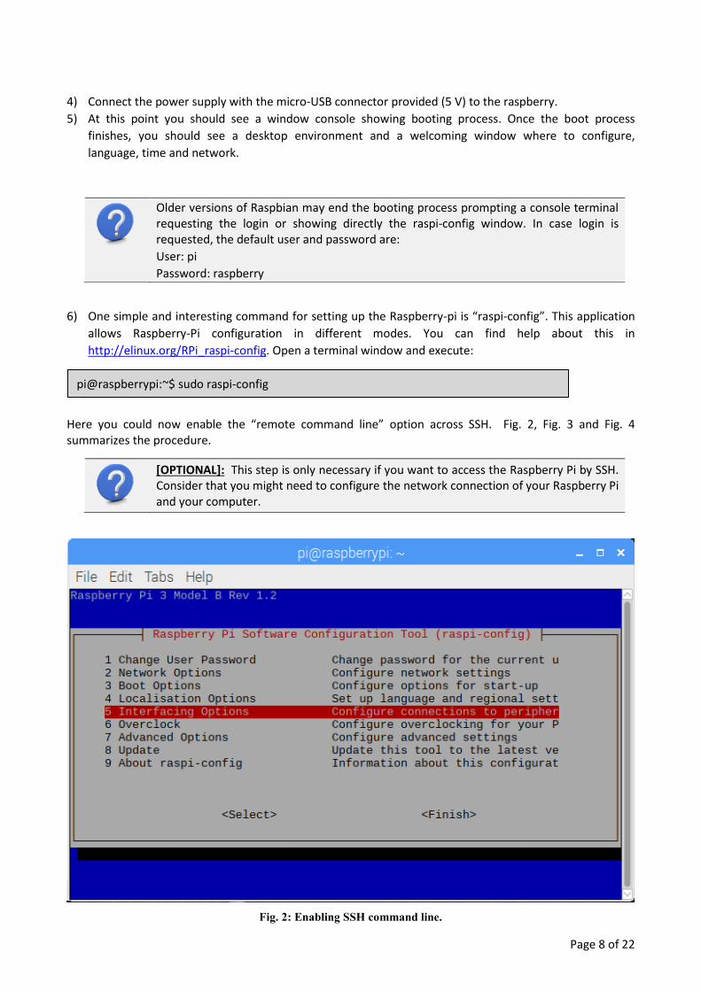
6) One simple and interesting command for setting up the Raspberry-pi is “raspi-config”. This application
allows Raspberry-Pi configuration in different modes. You can find help about this in
http://elinux.org/RPi_raspi-config. Open a terminal window and execute:
Here you could now enable the “remote command line” option across SSH. Fig. 2, Fig. 3 and Fig. 4 summarizes the procedure.
Fig. 2: Enabling SSH command line.
Older versions of Raspbian may end the booting process prompting a console terminal requesting the login or showing directly the raspi-config window. In case login is requested, the default user and password are:
User: pi
Password: raspberry
[OPTIONAL]: This step is only necessary if you want to access the Raspberry Pi by SSH. Consider that you might need to configure the network connection of your Raspberry Pi and your computer.
pi@raspberrypi:~$ sudo raspi-config

Page 9 of 22
Fig. 3: Enabling SSH command line.
Fig. 4: Enabling SSH command line.
Page 10 of 22
3.2 Updating Raspbian
In case you did not update the system during the first start up, the commands “apt-get update” and “apt-get upgrade” allow updating and upgrading respectively the software available in the Raspberry. This operation needs internet connection and it could take some minutes.
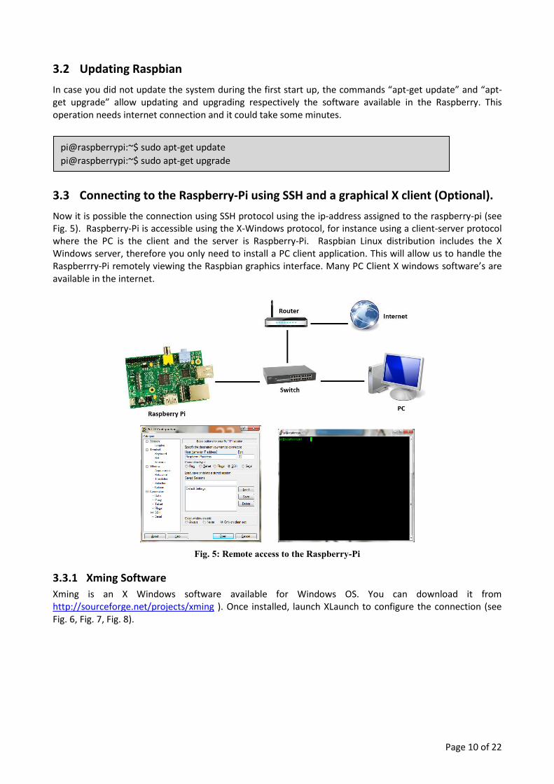
3.3 Connecting to the Raspberry-Pi using SSH and a graphical X client (Optional).
Now it is possible the connection using SSH protocol using the ip-address assigned to the raspberry-pi (see Fig. 5). Raspberry-Pi is accessible using the X-Windows protocol, for instance using a client-server protocol where the PC is the client and the server is Raspberry-Pi. Raspbian Linux distribution includes the X Windows server, therefore you only need to install a PC client application. This will allow us to handle the Raspberrry-Pi remotely viewing the Raspbian graphics interface. Many PC Client X windows software’s are available in the internet.
Fig. 5: Remote access to the Raspberry-Pi
3.3.1 Xming Software
Xming is an X Windows software available for Windows OS. You can download it from http://sourceforge.net/projects/xming ). Once installed, launch XLaunch to configure the connection (see Fig. 6, Fig. 7, Fig. 8).
pi@raspberrypi:~$ sudo apt-get update
pi@raspberrypi:~$ sudo apt-get upgrade

Page 11 of 22
Fig. 6: XLaunch
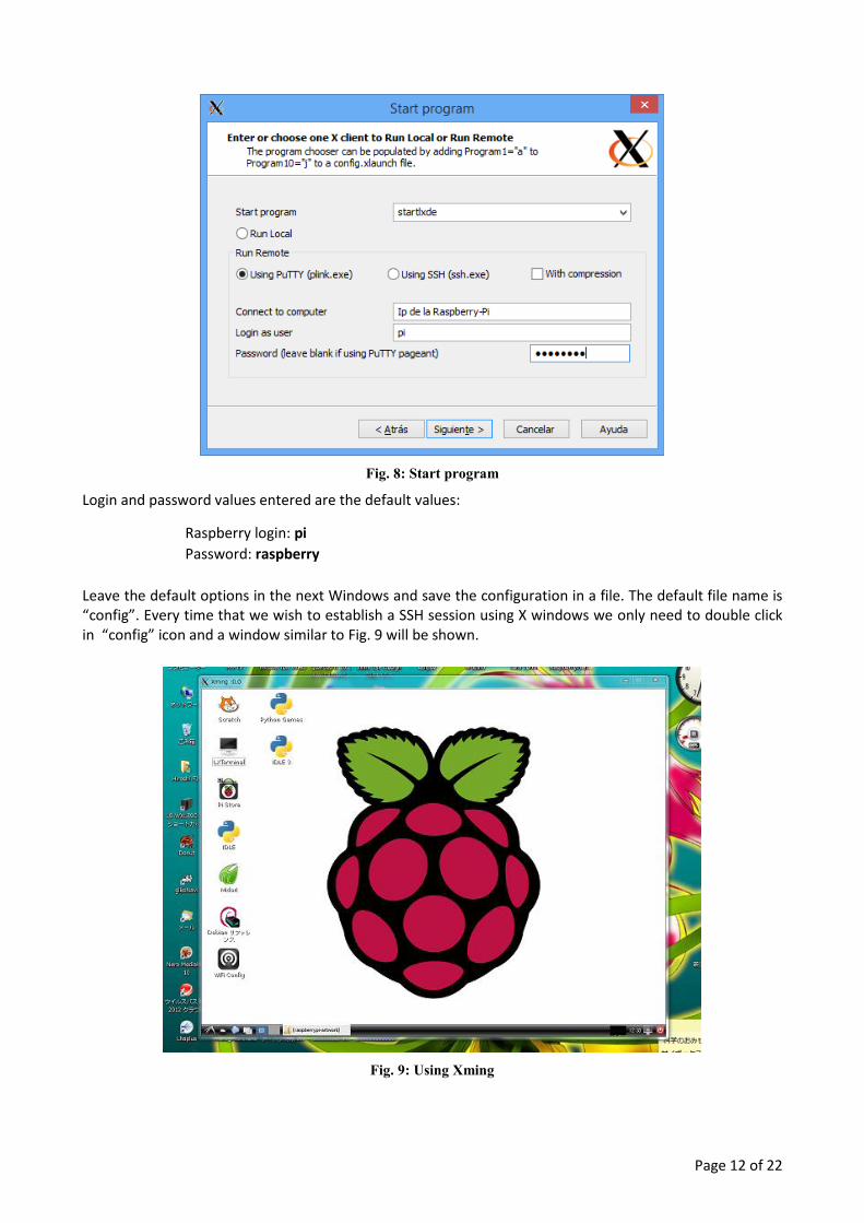
We can start a program when the session is established selecting the “Start a program option” (see Fig. 7). If you want to start the graphical interface select “startlxde” (see Fig. 8)
Fig. 7: Session Type, XLaunch
Page 12 of 22
Fig. 8: Start program
Login and password values entered are the default values:
Raspberry login: pi
Password: raspberry
Leave the default options in the next Windows and save the configuration in a file. The default file name is “config”. Every time that we wish to establish a SSH session using X windows we only need to double click in “config” icon and a window similar to Fig. 9 will be shown.
Fig. 9: Using Xming

Page 13 of 22
3.3.2 Moba Xterm Software
This software application is downloadable from http://mobaxterm.mobatek.net/download-home-edition.html. Download and install it. Configure a new session, writing the Raspberry-Pi ip address. In Advanced Settings select LXDE desktop in the Remote environment (see Fig. 10) to establish the session in graphic interface mode.
Fig. 10: Moba xterm, graphic mode
Settings values to establish a session in terminal mode is shown in the Fig. 11.
Fig. 11: Moba xterm, Terminal mode
Moba xterm can keep many opened sessions and they are accessible by tabs (see Fig. 12).

Page 14 of 22
Fig. 12: Opened Sessions Moba Xterm
When the sessions was configured, if the user selected the “Display SFTP Server” (see Fig. 10, Fig. 11) files between Raspberry-Pi <---> PC can be transferred.
Fig. 13: Sftp browser

Page 15 of 22
4 DISPLAYING RASPBERRY-PI MAC ADDRESS
1. Write login and password in Raspberry-pi an run the command “ifconfig”:
Fig. 14: ifconfig prompt.
HWaddr is MAC Address = b8:27:eb:b3:a9:0c
pi@raspberry:~$ ifconfig

Page 16 of 22
5 CONNECTING RPI TO INTERNET IN THE LABORATORY
5.1 Adding proxy configuration
1. Navigate to the folder /etc/apt/apt.conf.d/ (You can do this by clicking the second icon
along on the taskbar at the bottom of your desktop and typing in the location bar).
2. Right click in the folder and create a new file called ’10proxy’. 3. Right click on the new file and edit it. Type in the following lines:
Acquire::http::Proxy "http://proxy.lab.sec.upm.es:3128/";
Acquire::https::Proxy "http://proxy.lab.sec.upm.es:3128/";
Acquire::ftp::Proxy "http://proxy.lab.sec.upm.es:3128/";
4. Save the file.
5. Edit the file /etc/environment
export http_proxy="http://proxy.lab.sec.upm.es:3128/"
export https_proxy="http://proxy.lab.sec.upm.es:3128/"
export ftp_proxy="http://proxy.lab.sec.upm.es:3128/"
5.2 Using git with a proxy.
Execute this command in your git folder
git config --global http.proxy http://proxy.lab.sec.upm.es:3128

Page 17 of 22
6 CONNECTING SENSORS TO THE RASPBERRY-PI
6.1 Introduction
One powerful feature of the Raspberry Pi is the row of GPIO (general purpose input/output) pins along the edge of the board, next to the yellow video out socket.
Fig. 15: GPIO pins and layout
These pins are a physical interface between the Pi and the outside world. At the simplest level, you can think of them as switches that you can turn on or off (input) or that the Pi can turn on or off (output). Twenty seven of the forty pins are GPIO pins; the others are power pins, ground pins and EEPROM I2C pins.
You can program the pins to interact with the real world. Inputs don't have to come from a physical switch; it could be input from a sensor or a signal from another computer or device, for example. The output can also do anything, from turning on an LED to sending a signal or data to another device. If the Raspberry Pi is on a network, you can control devices that are attached to it from anywhere and those devices can send data back.

Page 18 of 22
The GPIO includes serial communication buses as UART, I2C and SPI. Using these buses it is possible to connect a lot of sensors to the Raspbery Pi.
6.2 First steps with Pi GPIO: Raspberry Pi Electronics Starter Kit
Monk Makes (http://www.monkmakes.com/rpi_esk/) offers a basic starter kit for Raspberry Pi that contains all the components needed to complete 10 simple experiments involving LEDs, thermistors, photoresistors and switches. The kit also offers the source code in Python to control the different experiments.
Fig. 16: Monk Makes Raspberry Pi Electronics Starter Kit.
You will use one of these kits to start using the Raspberry GPIO.
Follow the instructions located in the starter kit box and in the Web page http://www.monkmakes.com/rpi_esk/ to run the following experiments:
1. Project 1. Make a LED Blink
2. Project 3. RGB Color Display
6.3 Programming the Raspberry Pi in C language
6.3.1 Installing Code::Blocks IDE
In order to program the Raspberry Pi in C language you should install an Integrated Development Environment (IDE) such as Eclipse, Netbeans, Codeblocks, etc.
In this case, you will use the Codeblocks IDE. To install it, execute the following command:
After several minutes, the installation should finish, and the Code::Blocks IDE should appear under the Programming tab of the Menu.
pi@raspberrypi:~$ sudo apt-get install codeblocks

Page 19 of 22
6.3.2 wiringPi. GPIO Interface library
WiringPi (http://wiringpi.com/) is a GPIO access library written in C for the BCM2837 used in the Raspberry Pi 3. It’s released under the GNU LGPLv3 license and is usable from C and C++ and many other languages with suitable wrappers.
Following the instructions located in http://wiringpi.com/download-and-install/ try to download and install the wiringPi library by executing the following commands:
Once you have the library installed, you can use it from Codeblocks. For this purpose, you should add the libwiringPi.so in Menu Settings/Compiler and debugger/Linker settings > Link libraries > Add... library found in /usr/lib/libwiringPi.so.
Using Codeblocks and the wiringPi library, you should write the code, compile and try the following experiments:
1. Project 1. Make a LED Blink
In this experiment, one LED connected to a GPIO digital output pin of the Raspberry Pi must be blinking every second.
2. Project 3. RGB Color LED
To control the intensity of each RGB LED it is necessary to generate a PWM (Pulse Width Modulation) signal. In a PWM signal, the frequency remains stable while the duty cycle can change between 0 and 100 %. Modifying the duty cycle you can control the average value of the signal.
Fig. 17: PWM signal.
In this experiment you must codify an application that follows these rules:
Initial state: All LEDs remains OFF
pi@raspberrypi:~$ git clone git://git.drogon.net/wiringPi
pi@raspberrypi:~$ cd wiringPi
pi@raspberrypi:~$ ./build

Page 20 of 22
Next second: The RED LED increases progressively its intensity from 0% to 100%
Next 500 ms: All LEDs remains OFF
Next second: The GREEN LED increases progressively its intensity from 0% to 100%
Next 500 ms: All LEDs remains OFF
Next second: The BLUE LED increases progressively its intensity from 0% to 100%
Next 500 ms: All LEDs remains OFF
Go to Initial state
6.3.3 HIH-6120-021-001 Humidity and Temperature Sensor
The HIH-6120-021-001 is a Honeywell HumidIcon digital output-type relative humidity (RH) and temperature sensor combined in the same package. The communication with the sensor is performed via I2C bus, acting the sensor as slave using the default address 0x27.
Fig. 18: HIH-6120-021-001 Humidity/Temperature sensor, I2C.
6.3.3.1 I2C standard communication protocol
This is an excerpt of https://en.wikipedia.org/wiki/I%C2%B2C
6.3.3.1.1 Bus Overview
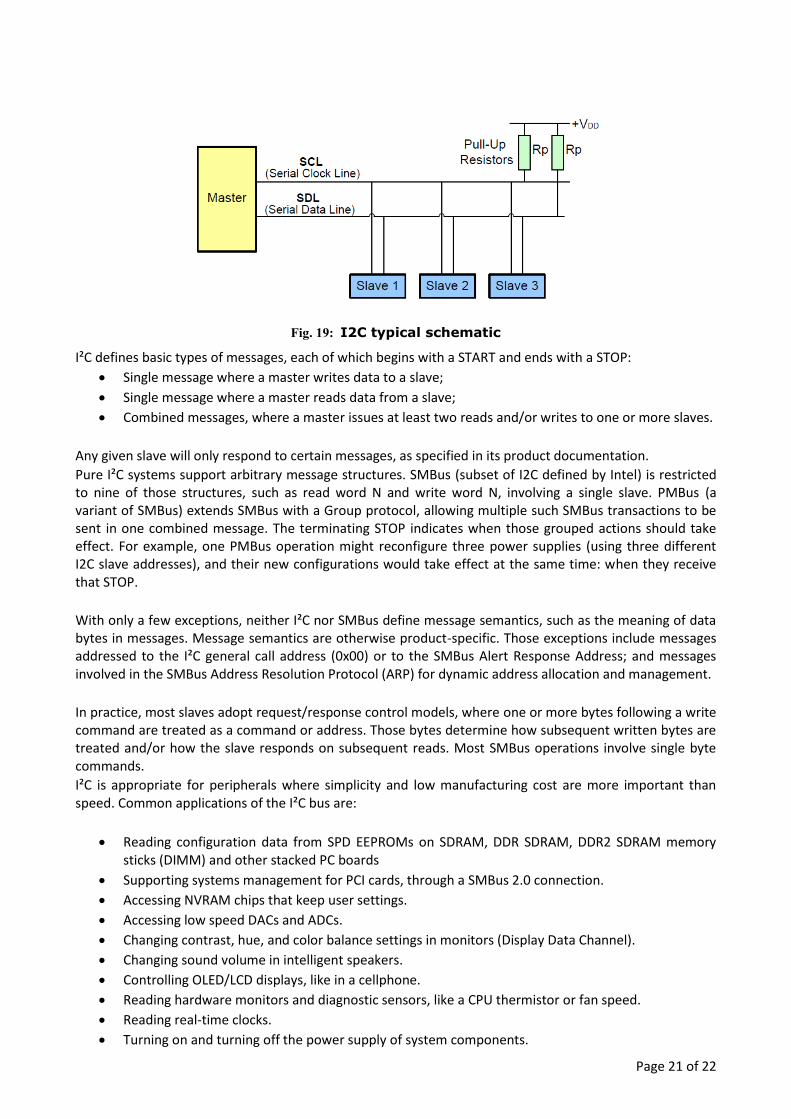
I²C uses only two bidirectional open-drain lines, Serial Data Line (SDA) and Serial Clock Line (SCL), pulled up with resistors. Typical voltages used are +5 V or +3.3 V although systems with other voltages are permitted. Therefore, pull-up resistors (Rp, Pull-Up Resistor) are needed. The value of these pull-up resistors is generally 3 kΩ-10 kΩ. In our specific case these resistors are already implemented in the Raspberry Pi PCB. I2C typical configuration is shown in Fig. 21.
Check WiringPi information about PWM and softPWM implementation in order to adjust properly the frequency and duty cycle.
Page 21 of 22
Fig. 19: I2C typical schematic
I²C defines basic types of messages, each of which begins with a START and ends with a STOP:
Single message where a master writes data to a slave;
Single message where a master reads data from a slave;
Combined messages, where a master issues at least two reads and/or writes to one or more slaves.
Any given slave will only respond to certain messages, as specified in its product documentation.
Pure I²C systems support arbitrary message structures. SMBus (subset of I2C defined by Intel) is restricted to nine of those structures, such as read word N and write word N, involving a single slave. PMBus (a variant of SMBus) extends SMBus with a Group protocol, allowing multiple such SMBus transactions to be sent in one combined message. The terminating STOP indicates when those grouped actions should take effect. For example, one PMBus operation might reconfigure three power supplies (using three different I2C slave addresses), and their new configurations would take effect at the same time: when they receive that STOP.
With only a few exceptions, neither I²C nor SMBus define message semantics, such as the meaning of data bytes in messages. Message semantics are otherwise product-specific. Those exceptions include messages addressed to the I²C general call address (0x00) or to the SMBus Alert Response Address; and messages involved in the SMBus Address Resolution Protocol (ARP) for dynamic address allocation and management.
In practice, most slaves adopt request/response control models, where one or more bytes following a write command are treated as a command or address. Those bytes determine how subsequent written bytes are treated and/or how the slave responds on subsequent reads. Most SMBus operations involve single byte commands.
I²C is appropriate for peripherals where simplicity and low manufacturing cost are more important than speed. Common applications of the I²C bus are:
Reading configuration data from SPD EEPROMs on SDRAM, DDR SDRAM, DDR2 SDRAM memory sticks (DIMM) and other stacked PC boards
Supporting systems management for PCI cards, through a SMBus 2.0 connection.
Accessing NVRAM chips that keep user settings.
Accessing low speed DACs and ADCs.
Changing contrast, hue, and color balance settings in monitors (Display Data Channel).
Changing sound volume in intelligent speakers.
Controlling OLED/LCD displays, like in a cellphone.
Reading hardware monitors and diagnostic sensors, like a CPU thermistor or fan speed.
Reading real-time clocks.
Turning on and turning off the power supply of system components.

Page 22 of 22
A particular strength of I²C is the capability of a microcontroller to control a network of device chips with just two general purpose I/O pins and software. Many other bus technologies used in similar applications, such as Serial Peripheral Interface Bus, require more pins and signals to connect devices.
6.3.3.2 Developing applications with HIH-6120-021-001
To use the I2C bus in the Raspberry Pi it will be necessary to enable it in the configuration files. To do this, run the following command, and enable the use of the I2C bus under the interface submenu:
i2c-tools is a set of I²C programs that make it easy to debug I²C devices without having to write any code. To install these tools, run the following command:
Once you have connected the sensor to the Raspberry Pi, you can check the i2c devices connected to the system using the following command:
You should obtain a response similar to the following, where the 0x27 address correspond to the used sensor.
0 1 2 3 4 5 6 7 8 9 a b c d e f
00: -- -- -- -- -- -- -- -- -- -- -- -- -- -- -- --
10: -- -- -- -- -- -- -- -- -- -- -- -- -- -- -- --
20: -- -- -- -- -- -- -- 27 -- -- -- -- -- -- -- --
30: -- -- -- -- -- -- -- -- -- -- -- -- -- -- -- --
40: -- -- -- -- -- -- -- -- -- -- -- -- -- -- -- --
50: -- -- -- -- -- -- -- -- -- -- -- -- -- -- -- --
60: -- -- -- -- -- -- -- -- -- -- -- -- -- -- -- --
70: -- -- -- -- -- -- -- -- -- -- -- -- -- -- -- --
Using Codeblocks, the students must investigate about functions and commands and implement a C/C++ program with the next features:
1. Show the temperature and humidity measurement on screen terminal using the I2C sensor.
2. The measurement readings will be shown every 3 seconds.
3. Date and time should be displayed in each measurement.
pi@raspberrypi:~$ i2cdetect –y 1
pi@raspberrypi:~$ sudo apt-get install i2c-tools
pi@raspberrypi:~$ sudo raspi-config
pi@raspberrypi:~$ ./i2c_sensor_HIH
06/09/2018 10:12:24
Temperature (ºC): 27.2
Humidity (%): 40.0
06/09/2018 10:12:27
Temperature (ºC): 27.0
Humidity (%): 41.3
06/09/2018 10:12:30
Temperature (ºC): 26.5
Humidity (%): 40.7

Page 23 of 22
4. If the temperature is greater than 27 ºC, the LED (used in Project 1) must be ON. 5. The RGB LED must be flashing (like in the Project 3), under the following conditions:
a. If the Humidity is under 40%, the RED led must be flashing b. If the Humidity is between 40% and 70%, the GREEN led must be flashing c. If the Humidity is upper 70%, the BLUE led must be flashing