iq4-controller - inteccontrols.cominteccontrols.com/ums/iq4_usermanual.pdf · iq4-controller four...
TRANSCRIPT

IQ4-CONTROLLER Four Channel
Monitoring and Control System
INSTALLATION OPERATION AND MAINTENANCE
MANUAL
12700 Stowe Dr., Ste 100 Poway, CA 92064
Ph: 858-578-7887Fx: 858-578-4633
Email: [email protected]
12700 Stowe Drive, Suite 100, Poway, CA 92064 | Ph: (858) 578.7887 & (888) GO.INTEC | relevantsolutions.com/inteccontrols

IQ4 CONTROLLER Operation And Maintenance Manual
IQ4 Controller Operation Manual Page 2 of 46 March 16, 2007 85350-001-000 Rev A
Table Of Contents
READ BEFORE OPERATING..............................................................................................................4
READ BEFORE OPERATING..............................................................................................................4
1. GLOSSARY ...................................................................................................................................4
2. GENERAL INFORMATION ........................................................................................................6
2.1 SYSTEM OVERVIEW ......................................................................................................................6 2.2 KEY FEATURES.............................................................................................................................7 2.3 SPECIFICATIONS ...........................................................................................................................8 3. INSTALLATION .........................................................................................................................12
3.1 UNPACKING THE EQUIPMENT .......................................................................................................12 3.2 TYPE AND LOCATION..................................................................................................................12 3.3 POSITIONING ..............................................................................................................................12 3.4 PHYSICAL DIMENSIONS...............................................................................................................13 3.5 CABLING....................................................................................................................................13 3.6 CONNECTORS .............................................................................................................................14 3.7 POWER SUPPLY CONNECTION......................................................................................................14
3.7.1 Input Power Supply and Digital/Smart Sensor Power Supply ................................................14 3.7.2 Proper Ground......................................................................................................................15 3.7.3 Wire and Cable.....................................................................................................................16 3.7.4 Stub ......................................................................................................................................16 3.7.5 Shield Ground.......................................................................................................................16
3.8 DIGITAL/SMART SENSOR PORT RS-485 INSTALLATION ................................................................17 3.8.1 RS-485 Terminator ...............................................................................................................17 3.8.2 RS-485 Driver Replacement..................................................................................................18
3.9 BUZZER, STROBE AND HORN OUTPUTS ........................................................................................19 3.10 RELAY MODULE BOARD INSTALLATION (OPTION)........................................................................19 3.11 4-20MA ANALOG OUTPUT MODULE BOARD INSTALLATION (OPTION) ..........................................20 3.12 UPSTREAM RS-485 MODULE BOARD INSTALLATION (OPTION) .....................................................21
3.12.1 RS-485 Terminator...........................................................................................................22 4. FUNCTION AND CONFIGURATION.......................................................................................23
4.1 INPUTS AND OUTPUTS ADDRESSING.............................................................................................23 4.2 KEYPAD AND INDICATORS...........................................................................................................23
4.2.1 Running Mode: Status View and Acknowledge Commands ....................................................24 4.2.2 Menu Mode: Database Configuration Menu Tree .................................................................25 4.2.3 LED indicators .....................................................................................................................27
4.3 SCROLL AND HOLD .....................................................................................................................27 4.4 VIEW OUTPUT DETAILS ..............................................................................................................27 4.5 LATCHED RELAY RESET..............................................................................................................28 4.6 HUSH BUZZER AND HORN ...........................................................................................................28 4.7 MENU “1_SYSTEM SETTING” ......................................................................................................29
4.7.1 Menu “1_System Setting” Flow Chart ..................................................................................29 4.7.2 Miscellaneous.......................................................................................................................30 4.7.3 4-20mA Output Calibrations .................................................................................................30 4.7.4 Change Password .................................................................................................................30 4.7.5 Link M-View .........................................................................................................................30
4.8 MENU “2_ZEROING CALIBRATION” .............................................................................................33 4.9 MENU “3_SPAN CALIBRATION”...................................................................................................33
Specifications subject to change without notice. | 85350-001-000 Rev A | USA 070316 | Page 2 of 44
12700 Stowe Drive, Suite 100, Poway, CA 92064 | Ph: (858) 578.7887 & (888) GO.INTEC | relevantsolutions.com/inteccontrols
IQ4 – UserManual
IQ4 CONTROLLER Operation And Maintenance Manual
IQ4 Controller Operation Manual Page 3 of 46 March 16, 2007 85350-001-000 Rev A
4.10 MENU “4_OUTPUT TESTING” ......................................................................................................34 4.11 HOW TO CREATE A DATABASE ....................................................................................................35
4.11.1 Requirements Analysis. ....................................................................................................35 4.11.2 Enter the database ...........................................................................................................35
4.12 MENU “5_SENSOR DATABASE” ...................................................................................................36 4.13 MENU “6_RELAY DATABASE”.....................................................................................................37
4.13.1 Relay Configurations........................................................................................................37 4.13.2 Modify Relay Database Flow Chart..................................................................................39 4.13.3 Modify Relay Sensor Assignments ....................................................................................40 4.13.4 Modify Relay Styles..........................................................................................................41
4.14 MENU “7_A-OUT DATABASE” ....................................................................................................42 4.15 MENU “8_BUZZER DATABASE” ...................................................................................................43 4.16 MENU “9_STROBE DATABASE” ...................................................................................................43 4.17 MENU “OUTPUT DISABLE”..........................................................................................................43 5. TROUBLESHOOTING...............................................................................................................44
Table Of Figures
FIGURE 1: IQ4-CONTROLLER PHYSICAL DIMENSIONS................................................................................13 FIGURE 2: IQ4 POWER SUPPLY BOARD INSTALLATION...............................................................................15 FIGURE 3: IQ4 CONNECTION WITH DIGITAL SENSORS.................................................................................17 FIGURE 4: IQ4 MAIN BOARD BOTTOM VIEW (UP SIDE DOWN) ...................................................................18 FIGURE 5: IQ4 I/O MOTHERBOARD TOP VIEW ..........................................................................................19 FIGURE 6: IQ4 RELAY BOARD TOP INSTALLATION ....................................................................................20 FIGURE 7: IQ4 4-20MA OUTPUT BOARD INSTALLATION ............................................................................20 FIGURE 8: IQ4 UPSTREAM RS-485 BOARD INSTALLATION.........................................................................21 FIGURE 9: IQ4 KEYPAD AND INDICATORS .................................................................................................23 FIGURE 10: IQ4 RUNNING MODE KEY FUNCTIONS FLOW CHART ...............................................................25 FIGURE 11: IQ4 MENU TREE FLOW CHART ...............................................................................................26 FIGURE 12: IQ4 MENU SYSTEM SETTINGS FLOW CHART ...........................................................................29 FIGURE 13: IQ4 MENU ZEROING CALIBRATION FLOW CHART....................................................................33 FIGURE 14: IQ4 MENU SPAN CALIBRATION FLOW CHART .........................................................................33 FIGURE 15: IQ4 MENU TESTING FLOW CHART ..........................................................................................34 FIGURE 16: IQ4 MENU SENSOR DATABASE FLOW CHART ..........................................................................36 FIGURE 17: IQ4 MENU RELAY DATABASE FLOW CHART............................................................................40 FIGURE 18: IQ4 MENU ANALOG OUTPUT DATABASE FLOW CHART............................................................42 FIGURE 19: IQ4 MENU OUTPUT DISABLE FLOW CHART.............................................................................44 FIGURE 20: IQ4 TROUBLESHOOTING TABLE..............................................................................................44
Specifications subject to change without notice. | 85350-001-000 Rev A | USA 070316 | Page 3 of 44
12700 Stowe Drive, Suite 100, Poway, CA 92064 | Ph: (858) 578.7887 & (888) GO.INTEC | relevantsolutions.com/inteccontrols
IQ4 – UserManual

IQ4 CONTROLLER Operation And Maintenance Manual
IQ4 Controller Operation Manual Page 4 of 46 March 16, 2007 85350-001-000 Rev A
READ BEFORE OPERATING
All individuals who have or will have the responsibility of using, maintaining, or servicing this product must carefully read this manual. The product will perform as designed only if it is used, maintained, and serviced in accordance with the manufacturer’s instructions.
1. Glossary
Actuate/De-Actuate: These terms are used instead of ‘make’ and ‘break’ to allow us to distinguish between performing an action due to an environmental condition and whether the contact may be closed (‘made’) or open (‘break’) because of our use of double throw contacts, and the option of normally energized relays.
Averaging: When setting alarms, the alarm can be set to operate on the basis of the average signal assigned to that relay or other outputs. It must be the same gas range.
Baud rate: A measure of the speed at which data is transferred over a digital communication link. Given as bit per second (bps). Generally the lower the speed, the more reliable.
bps: See Baud rate
Characteristic Impedance: The effects of capacitance and inductance of a pair of wires expressed as an equivalent resistance.
Configuration Database: System configuration requires entering a great deal of information concerning relay operation, sensor type and so on.
Download: Send data files ‘down’ to a slave device as from a computer to the IQ4 Controller.
Dry Contacts: The relay contacts are supplied without power applied to any output terminal.
Normally Energized: The relay coil is energized in the non-alarm state. This is sometimes referred to as ‘fail-safe’ because in the case of controller failure or loss of power, the relay contacts will open.
Normally Open Contacts: In the non-alarm state, but under power, the contacts are open.
Specifications subject to change without notice. | 85350-001-000 Rev A | USA 070316 | Page 4 of 44
12700 Stowe Drive, Suite 100, Poway, CA 92064 | Ph: (858) 578.7887 & (888) GO.INTEC | relevantsolutions.com/inteccontrols
IQ4 – UserManual

IQ4 CONTROLLER Operation And Maintenance Manual
IQ4 Controller Operation Manual Page 5 of 46 March 16, 2007 85350-001-000 Rev A
Latching: A relay once actuated remains actuated even though the condition has been removed. Requires a manual operation to reset.
Protocol: The actual language of communication between devices, as distinguished from the electrical standard.
RS-485 (properly EIA-485): A wiring and electrical standard for digital communication in a multi drop environment. It is a 2-wire system, with a differential signal allowing relative immunity to variations in grounds between devices. RS-485: maximum 32 transceivers per loop, 4000 ft (1300 meters) max. 120-ohm line termination required. (Line termination resistors are available on all M-Series devices via selectable jumpers).
Stub: A short wiring link branching from the main line.
Upload: Sending data files ‘up’ to a master device, as to a computer.
Voting: When more than one sensor and setpoint is assigned to a relay, then voting defines how many must reach the setpoint before the relay actuates.
M-Controller System: M-Controller System supports 32 digital sensor inputs, 8 channel4-20mA inputs, up to 99 Relay outputs, 3 Buzzers output, Strobe/Horn outputs as well as8 channel isolated 4-20mA outputs. Working with M-NET and M-View, it offers Ethernet/Internet capabilities as well as real time monitoring and data logging.
M-View: It is a Windows based software, which supports M-Controller and IQ4 Controller databases management and configuration as well as firmware updates.
Specifications subject to change without notice. | 85350-001-000 Rev A | USA 070316 | Page 5 of 44
12700 Stowe Drive, Suite 100, Poway, CA 92064 | Ph: (858) 578.7887 & (888) GO.INTEC | relevantsolutions.com/inteccontrols
IQ4 – UserManual

IQ4 CONTROLLER Operation And Maintenance Manual
IQ4 Controller Operation Manual Page 6 of 46 March 16, 2007 85350-001-000 Rev A
2. General Information
2.1 System Overview
This Four Channel Gas monitoring and Control System is a set of remote digital sensors, such as M-Series sensor/transmitter and IQ4S smart sensor, working with optional relay control modules, optional isolated 4-20mA analog output module and optional isolated RS-485 module together, they are monitored and controlled by the IQ4-Controller. M-Series digital sensor/transmitters comprise a group of remote mountable sensors complete with electronics, most of which have both analog and digital communications, and most of which have display and onboard relay options. IQ4S smart sensors have both analog and digital outputs, but have no display and onboard relay options.
The IQ4 Four Channel Controller is a microprocessor based and a flexible programmable controller with capability to work with up to four digital sensor/transmitters through itsRS-485 smart/digital sensor port. With relay module contained 4 removable relays, the controller can assign any one (or up to four) of the four digital sensor/transmitters to each relay. With isolated 4-20mA analog output module, the controller can output 4-20mA signals to other system according the selected sensor’s averaging reading or peaking reading. With isolated RS-485 output module, the IQ4-Controller can be connected to M-Controller system as four digital sensors.
The IQ4-Controller is intended to monitor, display, control and communicate a gasnetwork around the clock. It can control alarms, fans, horns, etc., when alarm conditions are reached. With isolated RS-485 port and isolated 4-20mA analog output, it is easy and reliable to embedded it to a large monitoring networks.
Additional features include 24 VDC transistor outputs for buzzer, strobe light and horn, and an RJ-11 phone jack for uploading and downloading the configuration database through RS-232 by running the Windows based software M-View. The configurationmay be altered either through a computer or through the front panel keypad.
The enclosure for the IQ4-Controller is rated IP66 & NEMA 4, 4X, 12 & 13 and is UL listed. Relay status indicator and RS-485 communication indicator are visible at the front of the enclosure.
Power supply is designed for 24VDC/AC for all devices in the system. A transformer forexternal mounting sized to the application can be supplied if requested.
Specifications subject to change without notice. | 85350-001-000 Rev A | USA 070316 | Page 6 of 44
12700 Stowe Drive, Suite 100, Poway, CA 92064 | Ph: (858) 578.7887 & (888) GO.INTEC | relevantsolutions.com/inteccontrols
IQ4 – UserManual

IQ4 CONTROLLER Operation And Maintenance Manual
IQ4 Controller Operation Manual Page 2 of 46 March 16, 2007 85350-001-000 Rev A
Table Of Contents
READ BEFORE OPERATING..............................................................................................................4
READ BEFORE OPERATING..............................................................................................................4
1. GLOSSARY ...................................................................................................................................4
2. GENERAL INFORMATION ........................................................................................................6 2.1 SYSTEM OVERVIEW ......................................................................................................................6 2.2 KEY FEATURES.............................................................................................................................7 2.3 SPECIFICATIONS ...........................................................................................................................8 3. INSTALLATION .........................................................................................................................12 3.1 UNPACKING THE EQUIPMENT .......................................................................................................12 3.2 TYPE AND LOCATION..................................................................................................................12 3.3 POSITIONING ..............................................................................................................................12 3.4 PHYSICAL DIMENSIONS...............................................................................................................13 3.5 CABLING....................................................................................................................................13 3.6 CONNECTORS .............................................................................................................................14 3.7 POWER SUPPLY CONNECTION......................................................................................................14
3.7.1 Input Power Supply and Digital/Smart Sensor Power Supply ................................................14 3.7.2 Proper Ground......................................................................................................................15 3.7.3 Wire and Cable.....................................................................................................................16 3.7.4 Stub ......................................................................................................................................16 3.7.5 Shield Ground.......................................................................................................................16
3.8 DIGITAL/SMART SENSOR PORT RS-485 INSTALLATION ................................................................17 3.8.1 RS-485 Terminator ...............................................................................................................17 3.8.2 RS-485 Driver Replacement..................................................................................................18
3.9 BUZZER, STROBE AND HORN OUTPUTS ........................................................................................19 3.10 RELAY MODULE BOARD INSTALLATION (OPTION)........................................................................19 3.11 4-20MA ANALOG OUTPUT MODULE BOARD INSTALLATION (OPTION) ..........................................20 3.12 UPSTREAM RS-485 MODULE BOARD INSTALLATION (OPTION) .....................................................21
3.12.1 RS-485 Terminator...........................................................................................................22 4. FUNCTION AND CONFIGURATION.......................................................................................23 4.1 INPUTS AND OUTPUTS ADDRESSING.............................................................................................23 4.2 KEYPAD AND INDICATORS...........................................................................................................23
4.2.1 Running Mode: Status View and Acknowledge Commands ....................................................24 4.2.2 Menu Mode: Database Configuration Menu Tree .................................................................25 4.2.3 LED indicators .....................................................................................................................27
4.3 SCROLL AND HOLD .....................................................................................................................27 4.4 VIEW OUTPUT DETAILS ..............................................................................................................27 4.5 LATCHED RELAY RESET..............................................................................................................28 4.6 HUSH BUZZER AND HORN ...........................................................................................................28 4.7 MENU “1_SYSTEM SETTING” ......................................................................................................29
4.7.1 Menu “1_System Setting” Flow Chart ..................................................................................29 4.7.2 Miscellaneous.......................................................................................................................30 4.7.3 4-20mA Output Calibrations .................................................................................................30 4.7.4 Change Password .................................................................................................................30 4.7.5 Link M-View .........................................................................................................................30
4.8 MENU “2_ZEROING CALIBRATION” .............................................................................................33 4.9 MENU “3_SPAN CALIBRATION”...................................................................................................33
Specifications subject to change without notice. | 85350-001-000 Rev A | USA 070316 | Page 7 of 44
12700 Stowe Drive, Suite 100, Poway, CA 92064 | Ph: (858) 578.7887 & (888) GO.INTEC | relevantsolutions.com/inteccontrols
IQ4 – UserManual

IQ4 CONTROLLER Operation And Maintenance Manual
IQ4 Controller Operation Manual Page 8 of 46 March 16, 2007 85350-001-000 Rev A
2.3 Specifications
Note: Installing or using this equipment in a manner not specified by the manufacturer could cause electric shock, bodily injury, or risk of fire.
Input Power: 24VDC nominal, range 20 to 28VDC
5.0A DC Total max.
~ 24VAC nominal, range 20 to 28VAC 50/60HZ
5.0A DC Total max.
Note: AC Power must be non-grounded (floating).
Note: No external over-current protection is required. Over-current protection is provided by means of fuses F1 and F2. See fuse specification below. Note: Certain devices operate on DC voltage only; the IQ4Controller does NOT convert an AC voltage input to a DC vol-tage output for the remote sensors.
24 VDC Input => 24 VDC Output
24 VAC Input => 24 VAC Output
Fuse: F1: 4A Slo-Blo Fuse
Bussmann: S506 Series, Time Delay, Glass Tube
Part Number: S506-4-R
Must be CSA/UL approved
F2: 1A Very Fast-Acting Fuse
Littelfuse: Axial Lead and Cartridge Fuse
Part Number: 0251001
Must be CSA/UL approved.
Power Switching:
Slide switch on Power Supply Board (SW1). This switch disconnects power to the main and I/O motherboard cards, as well as Digital/Smart Sensor Port. SW1 provides a convenient method to locally remove power from the IQ4-Controller and connected devicesfor wiring adjustments etc.
Specifications subject to change without notice. | 85350-001-000 Rev A | USA 070316 | Page 8 of 44
12700 Stowe Drive, Suite 100, Poway, CA 92064 | Ph: (858) 578.7887 & (888) GO.INTEC | relevantsolutions.com/inteccontrols
IQ4 – UserManual

IQ4 CONTROLLER Operation And Maintenance Manual
IQ4 Controller Operation Manual Page 9 of 46 March 16, 2007 85350-001-000 Rev A
Note: A switch or circuit breaker must be provided in theinstallation, which can remove power from the IQ4-Controller incase of emergency or any other related requirement. Since theIQ4-Controller enclosure can be screwed to prevent unwantedtampering, the internal power switch is not guaranteed to beaccessible. Feeding the IQ4-Controller power from a rack mainswitch or from a switch in a distribution box is adequate.
Enclosure: IP66 & NEMA 4, 4X, 12 & 13 ratings
UL listed 508 listed (File # E65324)
Environmental conditions:
Location:
Altitude:
Temperature:
Relative Humidity:
Pollution Degree:
Indoor or Outdoor
Up to 2 000 m
-20°C to 50 °C
95 % for temperatures up to 31 °C
Decreasing linearly to 80 % at 40 °C
2, in accordance with IEC 664
Keypad: 4 Tactile & Audible keypad
Display: 8 x 2 character display c/w backlight
Panel Indicators:
4 Communication Status LED’s (Green)
• Master TX
• Master RX
• Sensor TX
• Sensor RX
4 Relay Status LED’s (Red)
• Relay1 Status
• Relay2 Status
• Relay3 Status
• Relay4 Status
Optional Relay Module:
4 Pluggable Relays SPDT, Dry contacts
10.0 A maximum resistive 250VAC, 30 VDC
Specifications subject to change without notice. | 85350-001-000 Rev A | USA 070316 | Page 9 of 44
12700 Stowe Drive, Suite 100, Poway, CA 92064 | Ph: (858) 578.7887 & (888) GO.INTEC | relevantsolutions.com/inteccontrols
IQ4 – UserManual

IQ4 CONTROLLER Operation And Maintenance Manual
IQ4 Controller Operation Manual Page 10 of 46 March 16, 2007 85350-001-000 Rev A
7.5 A maximum inductive 240VAC
5.0 A maximum inductive 30 VDC
Optional
4-20mA Analog Output Module:
Isolated 4-20 milliamps signal
Two terminals: mA and GND, no need of extra power supply for the isolation
Max output impedance 600-ohm
Optional RS-485 Module:
Isolated RS-485 port with OptoMux protocol
Responds as a Slave (four sensors) using OptoMux protocol in a M-Controller Monitoring System
Buzzer, Horn and Strobe:
24VDC transistor output terminals are supplied for connection to buzzer and standard strobe and horn set
Maximum of 6 Watts each
Buzzer 1: Continuous
Buzzer 2: Double-tap Intermittent
Buzzer 3: Intermittent 50% duty cycle
Any Buzzer is actuated, the horn will be actuated
Strobe can be programmed individually
Digital Sensor Port:
24VAC/VDC and RS-485 with OptoMux protocol
RS-232 Interface:
RJ-11 Telephone jack
Primarily used for uploading and downloading configuration databases and updating IQ4-Controller firmware
Storage Temperature:
-40°C to 70°C
Size:
180mm X 120mm X 90mm
Weight:
Less than 1.5lbs (0.680 kg)
Specifications subject to change without notice. | 85350-001-000 Rev A | USA 070316 | Page 10 of 44
12700 Stowe Drive, Suite 100, Poway, CA 92064 | Ph: (858) 578.7887 & (888) GO.INTEC | relevantsolutions.com/inteccontrols
IQ4 – UserManual

IQ4 CONTROLLER Operation And Maintenance Manual
IQ4 Controller Operation Manual Page 11 of 46 March 16, 2007 85350-001-000 Rev A
Specifications subject to change without notice. | 85350-001-000 Rev A | USA 070316 | Page 11 of 44
12700 Stowe Drive, Suite 100, Poway, CA 92064 | Ph: (858) 578.7887 & (888) GO.INTEC | relevantsolutions.com/inteccontrols
IQ4 – UserManual

IQ4 CONTROLLER Operation And Maintenance Manual
IQ4 Controller Operation Manual Page 12 of 46 March 16, 2007 85350-001-000 Rev A
3. Installation
3.1 Unpacking the equipment
The IQ4-Controller is shipped with the following:
• The IQ4-Controller in a NEMA 4X enclosure
• M-View CD-ROM
• User Operation Manual
• Installation Drawing
• RJ11 to DB9 RS-232 Cable and Adapter
3.2 Type and Location
The IQ4-Controller is designed and certified for installation in a fixed location where is not subject to shock and vibration. Please observe the temperature and humidity specifications above for ambient conditions. Observe the possibility of leaks or possible water damage from cleaning done in the area.
If the IQ4-Controller is going to be operating at temperatures below the operatingtemperature, a controlled heater or strip is recommended to keep the temperature adequately warm. Contact your local distributor or the factory for additional information.
3.3 Positioning
The mounting height and location should provide easy access to the wiring terminals and front-panel. Backlighting is provided for the display in case of low lighting conditions.
It is recommended that controllers be installed 5 feet (1.5m) above the floor.
Specifications subject to change without notice. | 85350-001-000 Rev A | USA 070316 | Page 12 of 44
12700 Stowe Drive, Suite 100, Poway, CA 92064 | Ph: (858) 578.7887 & (888) GO.INTEC | relevantsolutions.com/inteccontrols
IQ4 – UserManual

IQ4 CONTROLLER Operation And Maintenance Manual
IQ4 Controller Operation Manual Page 13 of 46 March 16, 2007 85350-001-000 Rev A
3.4 Physical Dimensions
Figure 1: IQ4-Controller Physical Dimensions
3.5 Cabling
Approved cable conduit and conduit connectors should be used to ensure a safe and reliable installation. Check the local wiring code for more information. Make sure all conduit connectors are screwed in tight and that they are not coming in contact with any bare conductors.
You might drill an additional access hole to bring the wires into the NEMA 4X enclosure. The access hole should be drilled on the side of the enclosure.
Specifications subject to change without notice. | 85350-001-000 Rev A | USA 070316 | Page 13 of 44
12700 Stowe Drive, Suite 100, Poway, CA 92064 | Ph: (858) 578.7887 & (888) GO.INTEC | relevantsolutions.com/inteccontrols
IQ4 – UserManual

IQ4 CONTROLLER Operation And Maintenance Manual
IQ4 Controller Operation Manual Page 14 of 46 March 16, 2007 85350-001-000 Rev A
Warning: Be sure to look inside the unit prior to drilling so that to make sure there is sufficient clearance for the hole and fitting that you are using. Seal conduit to prevent foreign material from entering the enclosure.
3.6 Connectors Make sure to observe wiring to the correct terminal blocks.
Note: Incorrect wiring to any of the terminals of the IQ4-Controller couldcause permanent damage to the unit, which is not covered by the warranty. Incorrect wiring could also cause fire, electric shock, or bodily injury. Please observe the polarity on all connections.
Warning: Disconnect the main supply and switch off the IQ4-Controller when changing any of the wiring to the unit. Be especially cautious when wiring high voltage to the relays. Do not touch sensitive components on the circuit card to prevent static discharge damage to the unit.
3.7 Power Supply Connection
The IQ4-Controller power supply Voltage requirements are nominally 24VAC/DC. This increases flexibility in the field and reduces costs, especially in those areas where 24 VAC/DC power is available as standard. In those situations where 24 VAC/DC is not already available it is necessary to purchase a power supply or transformer.
It is necessary to bear in mind the actual installation when sizing the transformer. The installation requirements can run theoretically from only 24VA to 120VA. These systems ranging from a single controller, a few electrochemical sensors with no external option function module boards to a full 4 QTS-8000 Combustible sensors or 4 IIR-FREON Smart sensors with optional module boards. It is always best to allow some safety margin in designing power supplies, and 25% to 50% allowance for startup surges and future requirements is recommended.
3.7.1 Input Power Supply and Digital/Smart Sensor Power Supply
IQ4-Controller operates on 24VAC 50/60HZ or 24VDC. There are no selections required by the user to select the input power. The input power is connected to the Power Supply Board using the Terminal Block TB3 located inside the unit
Specifications subject to change without notice. | 85350-001-000 Rev A | USA 070316 | Page 14 of 44
12700 Stowe Drive, Suite 100, Poway, CA 92064 | Ph: (858) 578.7887 & (888) GO.INTEC | relevantsolutions.com/inteccontrols
IQ4 – UserManual

IQ4 CONTROLLER Operation And Maintenance Manual
IQ4 Controller Operation Manual Page 15 of 46 March 16, 2007 85350-001-000 Rev A
Note: Certain devices operate on DC voltage only; the IQ4-Controller doesNOT convert an AC voltage input to a DC voltage output for thedigital/smart sensors.
24 VDC Input => 24 VDC Output on the Digital/Smart Sensor Port
24 VAC Input => 24 VAC Output on the Digital/Smart Sensor Port
Note: AC Power must be non-grounded (floating).
The power supply for digital/smart sensor is outputted from the TB2 on the Power Supply Board.
Figure 2: IQ4 Power Supply Board Installation
3.7.2 Proper Ground
The IQ4-Controller must be grounded by connecting a true earth-ground to the ground
terminal designated by the symbol.
The IQ4-Controller can be damaged by power surges and lightening through the RS-485 line and power supply. Although the IQ4-Controller has built-in surge protection, we strongly recommend that additional protection be obtained for the unit and for any electronic equipment that is attached to the power supply and RS-485 lines. Power supply protection is especially important if you live in a lightening-prone area.
Note: Lightening damage is not covered under warranty.
Specifications subject to change without notice. | 85350-001-000 Rev A | USA 070316 | Page 15 of 44
12700 Stowe Drive, Suite 100, Poway, CA 92064 | Ph: (858) 578.7887 & (888) GO.INTEC | relevantsolutions.com/inteccontrols
IQ4 – UserManual

IQ4 CONTROLLER Operation And Maintenance Manual
IQ4 Controller Operation Manual Page 16 of 46 March 16, 2007 85350-001-000 Rev A
Note: IQ4-Controller Common/Power Supply Negative is not connected to Chassis Safety Ground.
Note: Digital/Smart sensors/transmitters may have different power supplies and may have different grounds or may have floating power supplies. The RS-485 electrical standard allows differences between grounds of ± 7 Volts.
3.7.3 Wire and Cable
The terminal block TB1, TB2 and TB3 accept 12 AWG to 24 AWG wire, Use 16 AWG or 18 AWG wire for Power Supply in long wiring runs. We recommend using BELDEN 9841 for communications. This wire has 120 ohm input impendence, which will eliminate RS-485 communication problems.
3.7.4 Stub
Short lengths of cable from the main cable over to a device are called Stubs. When the Baud rate (communication bit rate) is low – e.g. 2400 baud, then it is often possible to use short lengths of a few inches without seriously impairing the signal integrity, especially when overall distances are relatively short; however, this is taking a chance on garbling your signals and is not recommended. All stubs should be kept as short as possible, the maximum length of stub should not more than 5 inch.
3.7.5 Shield Ground
There are certain things to keep in mind for the shield.
• The shield must be grounded otherwise it can make the situation worse.
• Ground the shield at only one end to prevent ground loops.
• If you cut the cable then either ground each section of the shield at that point or connect the shields together to ground back at an origin point.
Specifications subject to change without notice. | 85350-001-000 Rev A | USA 070316 | Page 16 of 44
12700 Stowe Drive, Suite 100, Poway, CA 92064 | Ph: (858) 578.7887 & (888) GO.INTEC | relevantsolutions.com/inteccontrols
IQ4 – UserManual

IQ4 CONTROLLER Operation And Maintenance Manual
IQ4 Controller Operation Manual Page 17 of 46 March 16, 2007 85350-001-000 Rev A
3.8 Digital/Smart Sensor Port RS-485 Installation
Figure 3: IQ4 Connection with Digital Sensors
3.8.1 RS-485 Terminator
The terminator on each end of the RS485 loop is designed to match the electrical impedance characteristic of the twisted pair loop, and will prevent signal echoes from corrupting the data on the line. The terminator should be enabled on BOTH ends of the RS485 loop. Short and medium length modbus/485 loops can operate without the terminating resistor. Longer runs may require the terminating resistors. But adding terminator dramatically increases power consumption.
The IQ4-Controller supplies this resistor on its Main Board, and it is chosen using a jumper at J4.
Specifications subject to change without notice. | 85350-001-000 Rev A | USA 070316 | Page 17 of 44
12700 Stowe Drive, Suite 100, Poway, CA 92064 | Ph: (858) 578.7887 & (888) GO.INTEC | relevantsolutions.com/inteccontrols
IQ4 – UserManual

IQ4 CONTROLLER Operation And Maintenance Manual
IQ4 Controller Operation Manual Page 18 of 46 March 16, 2007 85350-001-000 Rev A
Figure 4: IQ4 Main Board Bottom View (Up side Down)
Factory default setting is disabled terminator.
Terminator Enabled / ON1 2 3
Terminator Disabled / OFF(Default)
1 2 3J4
J4
3.8.2 RS-485 Driver Replacement
RS-485 lines in heavy industrial environments are sometimes subjected to magnetic disturbances causing sufficient inducted power surges to damage the driver integrated circuit (IC). This IC U5 is socketed on the circuit card of Main Board for ease of replacement in the field.
U5: RS-485 TRANSCEIVER IND. TEMP PDIP8
Specifications subject to change without notice. | 85350-001-000 Rev A | USA 070316 | Page 18 of 44
12700 Stowe Drive, Suite 100, Poway, CA 92064 | Ph: (858) 578.7887 & (888) GO.INTEC | relevantsolutions.com/inteccontrols
IQ4 – UserManual

IQ4 CONTROLLER Operation And Maintenance Manual
IQ4 Controller Operation Manual Page 19 of 46 March 16, 2007 85350-001-000 Rev A
3.9 Buzzer, Strobe and Horn Outputs
The IQ4-Controller supports buzzers, strobe and horn outputs. Buzzer1 to buzzer 3 and strobe can be programmed individually, horn output would be actuated if any of buzzers is/are actuated.
Logically, IQ4-Controller supports 3 buzzers. Actually, the IQ4-Controller only needs one buzzer to connect to TB1. IQ4-Controller can drive the buzzer sound differently.
• Buzzer 1: Continuous, normally used to be high alarm buzzer
• Buzzer 2: Double-tap Intermittent, normally used to be low alarm buzzer
• Buzzer 3: Intermittent 50% duty cycle, normally used to be fault alarm buzzer
Figure 5: IQ4 I/O Motherboard Top View
The outputs are 24 VDC transistor outputs; the maximum current is not more than 300mA. They are located on the I/O motherboard inside the IQ4-Controller.
Note: Buzzers, Strobe and Horn are not included in the IQ4-Controller packing.
3.10 Relay Module Board Installation (Option)
Relay Module Board is an option for IQ4-Controller system. The Relay module is equippedwith four pluggable Single-Pole Double-Throw (SPDT) relays and four terminal blocksRLY1 to RLY4. Each relay can be programmed individually.
Switching capability of each relay is:
Specifications subject to change without notice. | 85350-001-000 Rev A | USA 070316 | Page 19 of 44
12700 Stowe Drive, Suite 100, Poway, CA 92064 | Ph: (858) 578.7887 & (888) GO.INTEC | relevantsolutions.com/inteccontrols
IQ4 – UserManual

IQ4 CONTROLLER Operation And Maintenance Manual
IQ4 Controller Operation Manual Page 20 of 46 March 16, 2007 85350-001-000 Rev A
• 10.0 A maximum resistive 250VAC, 30 VDC
• 7.5 A maximum inductive 240VAC
• 5.0 A maximum inductive 30 VDC
Figure 6: IQ4 Relay Board Top Installation
Relay outputs are usually used to control other equipment, such as fans, lights, horns, or visual alarm indicators.
3.11 4-20mA Analog Output Module Board Installation (Option)
The IQ4-Controller has an optional card that can provide one channel isolated 4-20 milliamp analog outputs with no need for separate power supply. The maximum output impedance is 600 ohms. The minimum isolation voltage is 1000 Vrms.
Figure 7: IQ4 4-20mA Output Board Installation
Connection Indicator will be turned on when 4-20mA loops are connected and will be turned off if the 4-20mA loops are open.
Specifications subject to change without notice. | 85350-001-000 Rev A | USA 070316 | Page 20 of 44
12700 Stowe Drive, Suite 100, Poway, CA 92064 | Ph: (858) 578.7887 & (888) GO.INTEC | relevantsolutions.com/inteccontrols
IQ4 – UserManual

IQ4 CONTROLLER Operation And Maintenance Manual
IQ4 Controller Operation Manual Page 21 of 46 March 16, 2007 85350-001-000 Rev A
Test point SIG+ and SIG- are used to measure the current online when the IQ4-Controller is working in the field
The analog output may be defined in complex ways allowing averaging of input signals or peak among input signals and assignment of different values to both 4 milliamps and 20 milliamps. You may even assign a gas concentration to 4 mA, which is higher than the concentration assigned to 20 milliamps. The IQ4-Controller will draw a straight line between.
The module can also be used to output 2-10VDC if the Jump J1 2-3 is connected. The default setting: J1 1-2 is connected that mean the output is 4-20mA analog output.
3.12 Upstream RS-485 Module Board Installation (Option)
The IQ4-Controller has an optional card that can provide one channel isolated RS-485 outputs with no need for separate power supply. The minimum isolation voltage is 1000 Vrms.
Figure 8: IQ4 Upstream RS-485 Board Installation
The upstream RS-485 port can be used to connect the IQ4-Controller to M-Controller System, so the IQ4-Controller can be integrated into a larger monitoring network. When it connects to M-Controller digital sensor bus, it can communicate with M-Controller through the RS-485 module by using OptoMux protocol, the IQ4-Controller works as one to four digital sensors in M-Controller digital sensor network. In order to work with M-Controller digital sensor bus, the following settings have to be set up in the IQ4-Controller System Setting Menu:
• Address: Default is 2
• Baud Rate: Default is 4800bps
Specifications subject to change without notice. | 85350-001-000 Rev A | USA 070316 | Page 21 of 44
12700 Stowe Drive, Suite 100, Poway, CA 92064 | Ph: (858) 578.7887 & (888) GO.INTEC | relevantsolutions.com/inteccontrols
IQ4 – UserManual

IQ4 CONTROLLER Operation And Maintenance Manual
IQ4 Controller Operation Manual Page 22 of 46 March 16, 2007 85350-001-000 Rev A
The parameter Address is used to define the IQ4-Controller address in the M-Controller digital sensor network. M-Controller allows the sensor address from 0 to 31. If the parameter Address is assigned to X (range from 0 to 28) in the IQ4-Controller, the sensor 0 to sensor 3 in the IQ4-Controller will occupy the M-Controller address X to X+3, any polling to the address X to X+3 from the M-Controller, the IQ4-Controller will reply the polling, even though some sensors among the sensor 0 to sensor 3 are not installed in IQ4 Controller. The IQ4-Controller will always occupy four address-space of M-Controller. For example, if the address is 2 in a IQ4-Controller and the IQ4-Controller is connected to an M-Controller, then the sensor 0 in the IQ4-Controller would be the sensor 2 in M-Controller sensor network, the sensor 1 in the IQ4-Controller would be the sensor 3 in M-Controller …, any polling to sensor 2 to sensor 5 out of M-Controller, the IQ4-Controller will reply the information on sensor 0 to sensor 3 to M-Controller.
The parameter Baud Rate should be the same as the Sensor Baud Rate defined in M-Controller system.
3.12.1 RS-485 Terminator
The IQ4-Controller RS-485 Board supplies the terminator resistor on the board, and it is chosen using a jumper at J1.
Factory default setting is disabled terminator.
Terminator Enabled / ON1 2 3
Terminator Disabled / OFF(Default)
1 2 3J1
J1
Specifications subject to change without notice. | 85350-001-000 Rev A | USA 070316 | Page 22 of 44
12700 Stowe Drive, Suite 100, Poway, CA 92064 | Ph: (858) 578.7887 & (888) GO.INTEC | relevantsolutions.com/inteccontrols
IQ4 – UserManual

IQ4 CONTROLLER Operation And Maintenance Manual
IQ4 Controller Operation Manual Page 23 of 46 March 16, 2007 85350-001-000 Rev A
4. Function and Configuration
4.1 Inputs and Outputs Addressing
The term “sensor” used throughout means a digitally communicating sensor unless otherwise stated.
The IQ4-Controller can support up to 4 remote digital sensor inputs. 4 relay outputs, 3 buzzers outputs, 1 strobe and 1 channel analog 4-20mA outputs.
Acceptable addresses:
• Sensors are addressed to Sensor0 to Sensor3 or S0 to S3
• Relays are addressed to Relay1 to Relay4 or R1 to R4
• Buzzers are addressed to Buzzer1 to Buzzer 3 or BZ1 to BZ3
• Strobe is addressed to Strobe or ST
• Analog Output is address to “A-Out” or “mA Out”
4.2 Keypad and Indicators
All database programming and configuration can be done through the front panel keypad, although this is practical only for short programs and program modifications. The following discussion and flow charts demonstrate the operation and menu pathways. In practice you will find that it is easier to use the keypad and menus than it is to read the reference descriptions. The menus provide prompting at each stage, and only a few rules need be memorized.
Figure 9: IQ4 Keypad and Indicators
Specifications subject to change without notice. | 85350-001-000 Rev A | USA 070316 | Page 23 of 44
12700 Stowe Drive, Suite 100, Poway, CA 92064 | Ph: (858) 578.7887 & (888) GO.INTEC | relevantsolutions.com/inteccontrols
IQ4 – UserManual

IQ4 CONTROLLER Operation And Maintenance Manual
IQ4 Controller Operation Manual Page 24 of 46 March 16, 2007 85350-001-000 Rev A
The buttons are structured into two sections:
Running Mode Buttons: Allows detailed views of status, and acknowledge and ‘Hush’ functions.
Menu Mode Buttons: Password controlled access to all the database setup and configuration menus.
4.2.1 Running Mode: Status View and Acknowledge Commands
In normal operation the display appears as follows.
Where
Snn = the Sensor number/address
Rnn = the Relay, Buzzer, Strobe or Analog Output
xxxx = the Gas concentration
uuu = units of measure
yyyy = the gas type
zzzz = output status
The buttons have the following functions:
• Scroll and Hold
• View Output Details
• Latched Relay Reset
• Hush Buzzer and Horn
Snn yyyy xxxx uuu
Rnn zzzz
Specifications subject to change without notice. | 85350-001-000 Rev A | USA 070316 | Page 24 of 44
12700 Stowe Drive, Suite 100, Poway, CA 92064 | Ph: (858) 578.7887 & (888) GO.INTEC | relevantsolutions.com/inteccontrols
IQ4 – UserManual

IQ4 CONTROLLER Operation And Maintenance Manual
IQ4 Controller Operation Manual Page 25 of 46 March 16, 2007 85350-001-000 Rev A
Is UP key?
NO
YES
Is DOWN key?
Is Exit/Hush key?
Is ENTER key?
Scroll and HoldDisplay
Display Detailabout Outputs
NO
YES
NO
YES
NO
YES
Hold 3 seconds?Reset all Relays in
Latched Satus
Hush all Buzzersin Alarm Status
YES
NO
Hold 3 seconds? YES
NO
PASSWORD> XXXX
Passoword is Correct?YES
NO
Scan Buttons
Figure 10: IQ4 Running Mode Key Functions Flow Chart
4.2.2 Menu Mode: Database Configuration Menu Tree
Changing database items is password controlled. Press button [Enter] for 3 seconds. You will then be prompted for a four-digit password. Once the password is accepted, you are allowed into the main menu tree. Press button [Up] or [Down] to scroll through the main branch headings, press button [Enter] to enter the function, press button [Exit/Hush] to exit to up level menu.
Factory default password is 4321.
Specifications subject to change without notice. | 85350-001-000 Rev A | USA 070316 | Page 25 of 44
12700 Stowe Drive, Suite 100, Poway, CA 92064 | Ph: (858) 578.7887 & (888) GO.INTEC | relevantsolutions.com/inteccontrols
IQ4 – UserManual

IQ4 CONTROLLER Operation And Maintenance Manual
IQ4 Controller Operation Manual Page 26 of 46 March 16, 2007 85350-001-000 Rev A
1_ SYSTEMSETTING
2_ ZEROCAL
3_ SPANCAL
4_ OUTPUTTESTING
5_ SENSORDATABASE
6_ RELAYDATABASE
7_ A-OUTDATABASE
8_ BUZZERDATABASE
9_ STROBEDATABASE
Down
Down
Down
Down
Down
Down
Down
Down
Up
Up
Up
Up
Up
Up
Up
Up
Up
Exit
Exit
Exit
Exit
Exit
Exit
Exit
Exit
Exit
Enter
Enter
Enter
Exit
ANALOG OUT DATABASESUBDIVISION
BUZZER DATABASESUBDIVISION
STROBE DATABASESUBDIVISION
Enter
Enter
Enter
Exit
Exit
Exit
RELAY DATABASESUBDIVISION
Enter
Exit
SYSTEM SETTINGSUBDIVISIONExit
A_ OUTPUTDISABLE
Down
Exit ALL OUTPUTS ARE DISABLEDFOR CALIBRATION OR TEST
Enter
Exit
Correct Password?
Yes
SENSOR DATABASESUBDIVISION
OUTPUT TESTINGSUBDIVISIONExit
No
Enter
Enter from Running Mode
SPAN CALIBRATIONSUBDIVISIONExit
ZEROING CALIBRATIONSUBDIVISIONExit
Enter
Returnto Running Mode
Enter
Figure 11: IQ4 Menu Tree Flow Chart
Note: While in the Menu Tree, all normal monitoring operations stop. The alarm status does not change.
Specifications subject to change without notice. | 85350-001-000 Rev A | USA 070316 | Page 26 of 44
12700 Stowe Drive, Suite 100, Poway, CA 92064 | Ph: (858) 578.7887 & (888) GO.INTEC | relevantsolutions.com/inteccontrols
IQ4 – UserManual

IQ4 CONTROLLER Operation And Maintenance Manual
IQ4 Controller Operation Manual Page 27 of 46 March 16, 2007 85350-001-000 Rev A
4.2.3 LED indicators
Master TX, RX: When the IQ4-Controller is connected to an M-Controller System, the traffic of the communication can be monitored visually through the two RS-485 indicators. One is RX LED, which indicates the data stream received in the M-Controller. The other is TX LED, which indicates the data stream out of the IQ4-Controller.
Sensor TX, RX: When the digital sensors are connected to the IQ4-Controller, the traffic of the communication can be monitored visually through the two RS-485 indicators. One is RX LED, which indicates the data stream replied from digital sensor and received in the IQ4-Controller. The other is TX LED, which indicates the data stream sent out of the IQ4 Controller to the digital sensors.
Note: If the TX LED or the RX LED is always ON, that means the communication has a problem. See Troubleshooting for RS-485.
Relay1-4 LED: Indicate the status of each relay. When the relay is actuated/closed, the Relay LED is ON. When the relay is de-actuated/open, the relay LED is OFF.
Note: If you set the relay to be Normally Energized Relay (Fail Safe), the relay LED will turn ON at non-alarm state and turn OFF at alarm state, because the LED reflects the relay coil status.
4.3 Scroll and Hold
Press button [UP] to scroll through the display items. One frame is for sensor, the next frame is to display output status. Once the button [UP] is pressed, the current display will stop at that point for two minutes if no other button is pressed, displaying the ongoing status or reading.
4.4 View Output Details
Press button [DOWN] to get a snap shot view of all the program details for the current displayed output such as relay, buzzer or strobe.
Definitions:
• NE = Normally Energized
• ND = Normally De-Energized
• V = Voting number in Voting Mode
• A = Averaging Mode
• D1 = On Delay has been set
Specifications subject to change without notice. | 85350-001-000 Rev A | USA 070316 | Page 27 of 44
12700 Stowe Drive, Suite 100, Poway, CA 92064 | Ph: (858) 578.7887 & (888) GO.INTEC | relevantsolutions.com/inteccontrols
IQ4 – UserManual

IQ4 CONTROLLER Operation And Maintenance Manual
IQ4 Controller Operation Manual Page 28 of 46 March 16, 2007 85350-001-000 Rev A
• DX = On Delay has not been set
• D0 = Off Delay has been set
• Dx = Off Delay has not been set
• L = latching
• nL = non-latching
• V. Rate = xx/yy Voting Mode only. e.g. 3/2 indicates that 3 sensors have passed the alarm threshold of 2 required for voting.
• A= yyyy/zzzz Average Mode only.
o yyyy = the Relay Actuate Average On Concentration
o zzzz = the Relay De-Actuate Average Off Concentration
• DELAY = xx/yy The number of minutes assigned to the On delay/Off delay
• Alarm xx Where xx = the actual number of sensors currently in alarm
4.5 Latched Relay Reset
To acknowledge a latched condition, press the [Exit/Hush] button for 3 seconds. All latched relays for which the alarm condition has been removed will reset. If the alarm condition (e.g. high gas concentration) is still present the relay(s) will not reset.
4.6 Hush Buzzer and Horn
Press the [Exit/Hush] button to silence the buzzer and horn. Press the Exit/Hush button again to remove the hush function.
Specifications subject to change without notice. | 85350-001-000 Rev A | USA 070316 | Page 28 of 44
12700 Stowe Drive, Suite 100, Poway, CA 92064 | Ph: (858) 578.7887 & (888) GO.INTEC | relevantsolutions.com/inteccontrols
IQ4 – UserManual

IQ4 CONTROLLER Operation And Maintenance Manual
IQ4 Controller Operation Manual Page 29 of 46 March 16, 2007 85350-001-000 Rev A
4.7 Menu “1_System Setting” System Settings contains general settings for monitor operations, communications and calibration.
4.7.1 Menu “1_System Setting” Flow Chart
ADDRESS 002
BAUDRATE4800 bps
SCROLL 3 SEC
BACKLIGHTON
4mA CAL 150
20mA CAL 910
CHANGEPASSWORD
LINKM-VIEW
NEW ADDR> 0001
ACCEPTED
New Rate> 4800
ACCEPTED
New Rate> 4
ACCEPTED
New Mode> AUTO
ACCEPTED
ADJ 4mA> 151
ACCEPTED
ADJ 20mA> 911
ACCEPTED
New PSW> NNNN
IN AGAIN> NNNN
ACCEPTED
Waiting. M-VIEWONLINE!
Up
EnterDown
Exit
Up
Up
Down
Down
Down
Up
Up
Up
Up
Down
Down
Down
Enter
Enter
Enter
Enter
Enter
Enter
Enter
Exit
Exit
Exit
Exit
Exit
Exit
Exit
Exit
Enter
Exit
Exit
EnterEnter
Enter
Enter
Enter
Enter
Enter
Enter
Exit
Exit
Exit
Exit
Exit
Exit
Exit
RETURNTO UP LEVEL
S S1
Up
S S1
DownPRESS KEY UP AND
KEY DOWN TO MIDIFY
Figure 12: IQ4 Menu System Settings Flow Chart
Specifications subject to change without notice. | 85350-001-000 Rev A | USA 070316 | Page 29 of 44
12700 Stowe Drive, Suite 100, Poway, CA 92064 | Ph: (858) 578.7887 & (888) GO.INTEC | relevantsolutions.com/inteccontrols
IQ4 – UserManual

IQ4 CONTROLLER Operation And Maintenance Manual
IQ4 Controller Operation Manual Page 30 of 46 March 16, 2007 85350-001-000 Rev A
4.7.2 Miscellaneous
Password: Default password is 4321.
Address: This is a base address used in lager monitoring network, such as in M-Controller system. Valid address is between 0 and 255.
Baud rate: Remote Sensor baud rate, default baud rate is 4800 bps. In IQ4-Controller System, the actual baud rate is always 4800bps even you set Baud Rate to another value.
Scroll Rate: In normal operation the sensor and relay status information scrolls automatically. Set the number of seconds for each item to be displayed. Default value is 3 seconds.
Backlight: The LCD backlight can be set to Always Off, Always On and Power Saver. In Power Saving mode, the backlight will turn on for 10 seconds after any button has been pressed. Default setting is Always ON mode.
4.7.3 4-20mA Output Calibrations
4mA Cal:
20mA Cal:
These values are established during factory calibration and should not require recalibration in the field. Do not attempt to modify these settings in the field.
Changing these values will change the analog output signal scale.
Warning: This procedure is part of factory setup. In most circumstances it will not be necessary to perform this procedure in the field. These functions require the use of precision reference instrumentation.
4.7.4 Change Password
Change Password allows any combination of up to four digits.
Warning: Be sure that you record the new password in a safe and secure location!
4.7.5 Link M-View
The IQ4 Controller can be fully configured and programmed from the keypad; however, for even moderately complex networks this task becomes tedious. Therefore, we have supplied an interface and computer program (M-View) to allow all database programming to be setup on a computer or laptop and downloaded to the IQ4 Controller.
Specifications subject to change without notice. | 85350-001-000 Rev A | USA 070316 | Page 30 of 44
12700 Stowe Drive, Suite 100, Poway, CA 92064 | Ph: (858) 578.7887 & (888) GO.INTEC | relevantsolutions.com/inteccontrols
IQ4 – UserManual

IQ4 CONTROLLER Operation And Maintenance Manual
IQ4 Controller Operation Manual Page 31 of 46 March 16, 2007 85350-001-000 Rev A
Interface adapters and M-View CD-ROM are supplied in the packaging.
The adapter is 9-pin female (COMM) to RJ-11 adapter.
The M-View is Windows-based software that has been designed as an easy to use configuration software package, greatly reducing the lengthy task of entering individual keystrokes through the keypad to quick configuration with the mouse. M-View allows for both programming and audit control, as you may download, upload and save programs to disk. M-View currently supports M-Controller and IQ4-Controller. Professional Version M-View also can Real Time Monitor the current readings and statuses of M-Controller, Data logging these readings and statuses and Historical Data Review. IQ4 does not have Real Time Monitoring function. But you can use M-View to config the database in IQ4 Controller and update its firmware through the RS-232 port J1 (RJ11 telephone jack) on the Main Board.
Minimum system requirements:
Operating System: Windows 98 or later
Ram: 256 Megabyte of RAM
Hard drive: 500 Megabytes free
Speed: Any
Mouse: Preferred (can navigate by ‘tab’)
Spare Serial Port: Anyone between COM1 to COM6
Note: If your computer has no serial port, call for USB to Serial Adapter.
To install M-View, insert the CD into the computer and run Setup.exe. Follow the instructions on the screen.
If your computer has a previous version M-View installed, the setup program will remove it first, you have to run Setup.exe again to install the latest version M-View.
In order to upload and download databases from a computer, IQ4-Controller must betold to “Link M-View”. The microprocessor functions for the communications to thecomputer utilize the same pins on the microprocessor as for the upstream RS-485 Module interface. You can have communication to the computer based M-View programor you can have communications via the upstream RS-485 Module to M-Controller, butyou cannot have both at the same time. Entering “Link M-View” you disable the upstream
Specifications subject to change without notice. | 85350-001-000 Rev A | USA 070316 | Page 31 of 44
12700 Stowe Drive, Suite 100, Poway, CA 92064 | Ph: (858) 578.7887 & (888) GO.INTEC | relevantsolutions.com/inteccontrols
IQ4 – UserManual

IQ4 CONTROLLER Operation And Maintenance Manual
IQ4 Controller Operation Manual Page 32 of 46 March 16, 2007 85350-001-000 Rev A
RS-485 interface. The RS-232 connection through the RJ-11 telephone jack J1 will nowbe enabled.
How to Connect IQ4-Controller to PC M-View
• Connect the adapter and cable to a PC serial port and port J1 on the IQ4-ControllerMain Board
• Press and Hold button [Enter] for 3 seconds on IQ4-Controller
• Input Password to enter Menu Mode
• Browse Menu to [1_System Setting] => [Link M-View], Press button [Enter]
• Run M-View on your computer or laptop
• Click [Search and Download] to search IQ4-Controller
• If M-View displays “IQ4-Controller is online”, then you can read databases fromIQ4-Controller, modify the databases and then write back to IQ4-Controller
• If M-View displays “Device is offline”, see Troubleshooting in the end of themanual
Warning: The IQ4-Controller must be in “Link M-View” => “Waiting…” statusto receive signals from M-View through the RS-232 port J1 (RJ11telephone jack). The RS-232 port is logically shared with the upstream RS-485 port.
Note: You can see the IQ4-Controller firmware version in M-View Polling Status window, it is the current firmware version in the connected IQ4 Controller, this version number can also be seen in IQ4-Controller LCD when you power up the IQ4-Controller. Check the IQ4-Controller Firmware Version in M-View [Help]=>[About], if you found the M-View has a later version of IQ4-Controller Firmware, you can click [Programming] in the M-View Screen to update the firmware in the IQ4-Controller. M-View does not check the firmware version with IQ4 Controller automatically, but it does the check with M-Controller automatically.
Specifications subject to change without notice. | 85350-001-000 Rev A | USA 070316 | Page 32 of 44
12700 Stowe Drive, Suite 100, Poway, CA 92064 | Ph: (858) 578.7887 & (888) GO.INTEC | relevantsolutions.com/inteccontrols
IQ4 – UserManual
IQ4 CONTROLLER Operation And Maintenance Manual
IQ4 Controller Operation Manual Page 33 of 46 March 16, 2007 85350-001-000 Rev A
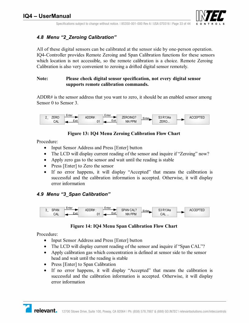
4.8 Menu “2_Zeroing Calibration”
All of these digital sensors can be calibrated at the sensor side by one-person operation.IQ4-Controller provides Remote Zeroing and Span Calibration functions for these sensorswhich location is not accessible, so the remote calibration is a choice. Remote ZeroingCalibration is also very convenient to zeroing a drifted digital sensor remotely.
Note: Please check digital sensor specification, not every digital sensor supports remote calibration commands.
ADDR# is the sensor address that you want to zero, it should be an enabled sensor among Sensor 0 to Sensor 3.
2_ ZEROCAL
ZEROING?NN PPM
S3 R134aZERO...
ACCEPTEDEnter
ExitEnterADDR# :
01
Enter
Exit
Figure 13: IQ4 Menu Zeroing Calibration Flow Chart
Procedure: • Input Sensor Address and Press [Enter] button • The LCD will display current reading of the sensor and inquire if “Zeroing” now? • Apply zero gas to the sensor and wait until the reading is stable • Press [Enter] to Zero the sensor • If no error happens, it will display “Accepted” that means the calibration is
successful and the calibration information is accepted. Otherwise, it will display error information
4.9 Menu “3_Span Calibration”
3_ SPANCAL
SPAN CAL?NN PPM
S3 R134aCAL ...
ACCEPTEDEnter
ExitEnterADDR# :
01
Enter
Exit
Figure 14: IQ4 Menu Span Calibration Flow Chart
Procedure: • Input Sensor Address and Press [Enter] button • The LCD will display current reading of the sensor and inquire if “Span CAL”? • Apply calibration gas which concentration is defined at sensor side to the sensor
head and wait until the reading is stable • Press [Enter] to Span Calibration • If no error happens, it will display “Accepted” that means the calibration is
successful and the calibration information is accepted. Otherwise, it will display error information
Specifications subject to change without notice. | 85350-001-000 Rev A | USA 070316 | Page 33 of 44
12700 Stowe Drive, Suite 100, Poway, CA 92064 | Ph: (858) 578.7887 & (888) GO.INTEC | relevantsolutions.com/inteccontrols
IQ4 – UserManual

IQ4 CONTROLLER Operation And Maintenance Manual
IQ4 Controller Operation Manual Page 34 of 46 March 16, 2007 85350-001-000 Rev A
4.10 Menu “4_Output Testing”
For system installation testing, it is necessary to force relay, buzzer and strobe actions. Enter this branch as shown in the flow diagram. Strobe and Horn tests are simple forces as shown. Relay testing is more complicated.
The Relay Testing feature allows the user to force actuation on each relay. This function forces an Actuate vs. De-actuate action, not an energized vs. non-energized action. Therefore the user must be aware of those relays which have been defined as normally energized or not normally energized.
STROBETEST
RELAYTEST
BUZZERTEST
HORNTEST
A-OUTTEST
RELAY 1? RELAYON
RELAY 2?
RELAY 3?
BUZZERON
BUZZEROFF
HORNON
HORNOFF
STROBEON
STROBEOFF
OUTPUT4mA
OUTPUT20mA
Up
Down
Exit
Up
Up
Up
Up
Down
Down
Down
F F1
F F1
RELAYON
RELAYON
Enter
Enter
Enter
Enter
Enter
Enter
Enter
Exit
Down
Down
Up
Up
Exit
Enter
Enter
Enter
Enter
Exit
Exit
Exit
Exit
Enter
Enter
Enter
Enter
Enter
Enter
Enter
Enter
Down
Exit
Exit
Exit
Exit
Exit
RETURNTO UP LEVEL
Exit
RELAY 4? RELAYON
Enter
Enter
DownUp
Exit
Figure 15: IQ4 Menu Testing Flow Chart
Specifications subject to change without notice. | 85350-001-000 Rev A | USA 070316 | Page 34 of 44
12700 Stowe Drive, Suite 100, Poway, CA 92064 | Ph: (858) 578.7887 & (888) GO.INTEC | relevantsolutions.com/inteccontrols
IQ4 – UserManual

IQ4 CONTROLLER Operation And Maintenance Manual
IQ4 Controller Operation Manual Page 35 of 46 March 16, 2007 85350-001-000 Rev A
4.11 How to Create a Database
The base concept is to tell the IQ4-Controller what sensors are connected and then tell it how the relays and other outputs function. Finally tell the IQ4-Controller how the sensors and relays work together.
Following these steps will help you to create your database quickly and easily:
4.11.1 Requirements Analysis.
Before you create your database, you should write out a requirements analysis.
A. How many remote sensors are there in your system? For each sensor, list its address.
B. Do you need 4-20mA analog output? If yes, list the concentration at 4mA and the concentration at 20mA, and which one or more sensors are dedicated to the output?
C. Do you need a relay board? What kind of relay style? Normally Energized? Latching? Voting mode or Average mode? Time delay? How many minutes for On Delay and Off Delay? List all the assigned sensors to each relay. If the relay works in Voting mode, list On Concentration and Off Concentration for each sensor. If the relay works in Averaging mode, list Averaging On Concentration and Averaging Off Concentration for the relay.
D. Do you need a Buzzer, Horn and Strobe? If yes, see Relay setup above.
E. Do you want to connect the IQ4-Controller to PLC or M-Controller system? If yes, then you need a 4-20mA output Board or a upstream RS-485 Board.
F. Setup system settings, such as Address, Password, Screen scroll rate and LCD Backlight mode.
4.11.2 Enter the database
The database can be input either using M-View to download and upload the database to/from IQ4-Controller or using the keypad on the IQ4-Controller.
Create database procedures:
A. Enable all digital sensors in Sensor Database.
Specifications subject to change without notice. | 85350-001-000 Rev A | USA 070316 | Page 35 of 44
12700 Stowe Drive, Suite 100, Poway, CA 92064 | Ph: (858) 578.7887 & (888) GO.INTEC | relevantsolutions.com/inteccontrols
IQ4 – UserManual

IQ4 CONTROLLER Operation And Maintenance Manual
IQ4 Controller Operation Manual Page 36 of 46 March 16, 2007 85350-001-000 Rev A
Note: You must have enabled each required sensor first before you can assign it to a relay or analog output function.
B. Setup all relay styles if equipped.
C. Setup all analog outputs if equipped.
D. Setup buzzers and strobe if equipped.
E. Setup system settings.
Below description is to show you the procedures of setup database through the keypad.
4.12 Menu “5_Sensor Database”
In order to assign a sensor to any of the output devices (relays, buzzers, etc) the sensor must already have been enabled in the sensor database.
Sensor Enable: The IQ4-Controller must be told which sensor is attached to the communication system. Then the IQ4-Controller will get the sensor information from the sensor using OptoMux protocol. Such as Gas Type and Gas Unit.
When you input a sensor number and try to add or remove the sensor from the sensor database, if the sensor is existed in the database, the sensor will be disabled and deleted. If the sensor does not exist in the database, the sensor will be enabled and added to the database.
5_ SENSORDATABASE
SENSORDELETED!
LIB: S0XMODIFY?
ADDR#:01
SENSORADDED!Enter
Exit
Enter
Exit
Display all EnabledSensors in Database:LIB,Click UP/DOWN key to
browse the sensors.
If the sensor doesnot exist in LIB.
Enter
Enter
If the sensor doesexist in LIB.
Figure 16: IQ4 Menu Sensor Database Flow Chart
Specifications subject to change without notice. | 85350-001-000 Rev A | USA 070316 | Page 36 of 44
12700 Stowe Drive, Suite 100, Poway, CA 92064 | Ph: (858) 578.7887 & (888) GO.INTEC | relevantsolutions.com/inteccontrols
IQ4 – UserManual

IQ4 CONTROLLER Operation And Maintenance Manual
IQ4 Controller Operation Manual Page 37 of 46 March 16, 2007 85350-001-000 Rev A
4.13 Menu “6_Relay Database”
4.13.1 Relay Configurations
Relay configurations may be styled in two basic ways: Voting and Averaging. Each method allows certain advantages and limitations. Common functions apply to both styles.
4.13.1.1 Common Functions
ON Delay (“Delay on Actuation” or “Delay on Make”): For each relay a separate time delay may be set from 0 to 59 minutes before an alarm condition will cause the relay to actuate. Default is 01 minute.
OFF Delay (“Delay on De-Actuation” or “Delay on Break”): For each relay a separate time delay may be set from 0 to 59 minutes before a return to a non-alarming signal condition will cause the relay to de-actuate. Default is 01 minute.
Normally/Not-Normally Energized. Each relay may be individually set to be Normally or Not Normally Energized.
Latching: Each relay may be set to latch in Actuate status until acknowledged by a front-panel action. Hold the button [Exit/Hush] for 3 seconds.
4.13.1.2 Voting Mode
Voting Number: For a given list of sensors assigned to a relay actuation list, this number indicates the minimum number of sensors that must pass or equal their alarm “On” concentration before the relay will actuate.
Assign Sensor: Each relay may be assigned to any one or more of the enabled sensors in the database.
If On Concentration is greater than or equal to Off Concentration:
On Concentration: For each sensor, set the concentration at or above which the relay will actuate.
Off Concentration: For each sensor, set the concentration at or below which the relay will de-actuate.
If On Concentration is less than Off Concentration:
Specifications subject to change without notice. | 85350-001-000 Rev A | USA 070316 | Page 37 of 44
12700 Stowe Drive, Suite 100, Poway, CA 92064 | Ph: (858) 578.7887 & (888) GO.INTEC | relevantsolutions.com/inteccontrols
IQ4 – UserManual

IQ4 CONTROLLER Operation And Maintenance Manual
IQ4 Controller Operation Manual Page 38 of 46 March 16, 2007 85350-001-000 Rev A
On Concentration: For each sensor, set the concentration below which the relay will actuate.
Off Concentration: For each sensor, set the concentration above which the relay will de-actuate.
Fault Actuation Flag: For each sensor sets this flag for actuation if the sensor reports Fault or drops off-line. In case of a dedicated Fail relay, then set the On Concentration and Off concentrations to zero (0) to disable actuation on gas concentration for that sensor.
4.13.1.3 Averaging Mode
Averaging mode is default. IQ4-Controller will calculate the averaging reading of assigned sensors and use the averaging reading to compare the “Average On” and “Average Off” to decide if actuating the output or de-actuating the output.
Note: The user must assign sensors with the same gas type and same units only.
If Average On is great than or equal to Average Off:
Average On: The gas concentration at or above which the average of all the sensors assigned to this relay will cause the relay to actuate.
Average Off: The gas concentration at or below which the average of all the sensors assigned to this relay will cause the relay to de-actuate.
If Average On is less than Average Off:
Average On: The gas concentration at or below which the average of all the sensors assigned to this relay will cause the relay to actuate.
Average Off: The gas concentration at or above which the average of all the sensors assigned to this relay will cause the relay to de-actuate.
Specifications subject to change without notice. | 85350-001-000 Rev A | USA 070316 | Page 38 of 44
12700 Stowe Drive, Suite 100, Poway, CA 92064 | Ph: (858) 578.7887 & (888) GO.INTEC | relevantsolutions.com/inteccontrols
IQ4 – UserManual

IQ4 CONTROLLER Operation And Maintenance Manual
IQ4 Controller Operation Manual Page 39 of 46 March 16, 2007 85350-001-000 Rev A
4.13.2 Modify Relay Database Flow Chart
The Relays and other output devices have two related databases: the Work Style which includes time delays, voting and so on, and the Assign Sensor which lists the sensors which are assigned to that relay, together with the alarm settings associated with that sensor as applied to that relay only. Usually, first set a relay “Work Style”, then set the relay “Assign Sensor”.
1. ASSIGNSENSOR
2. WORKSTYLE
R1 ND AMODIFY?
1.NORMALENERGIZE
2.NORMALDE-ENERGIZE
1. WITHLATCHING
2. NONELATCHING
1. VOTINGMODE
2. AVERAGE MODE
AV-ON #?> NNNN
AV-OFF #?> NNNN
VOTE #?NN
ON-DLY#?NN
OFF-DLY#?NN
FINISHED!
R1 ND AMODIFY?
R1: S03MODIFY?
SENSOR#?NN
SENSOR DISABLED!
SENSORDELETED!
SENSORADDED!
R R1
R R1
Up
Down
Up
Down
Enter
Exit
UpDown
Enter
Exit
Enter
Enter
Exit
Exit
Enter
Exit
EnterExit
DownUp
UpDown
Enter
Exit
Enter
Exit
Enter
Exit
Enter
ExitEnter
Enter
Enter
Exit
Exit
Exit
RETURNTO UP LEVEL
Display theRelay Status
Display allSensorsassigned tothe relay.Click UP/DOWN keyto browsethesensors.
Display the Relay Status
Enter
EnterEnter
Enter
RELAYDELETED!
FINISHED!
ALM ON#?> NNNN
ALM OFF#?> NNNN
FAULT?ON/OFF
Enter
Exit
Enter
Exit
Enter
Enter
Enter
IF THE RELAYWORKS IN
VOTING MODE
IF THE RELAYWORKS IN
AVERAGING MODE
IF SENSOR HASBEEN ASSIGNEDTO THE RELAY
IF SENSOR ISDISABLED
IF THE RELAY ISENABLED
IF THE RELAY IS DISABLED
Specifications subject to change without notice. | 85350-001-000 Rev A | USA 070316 | Page 39 of 44
12700 Stowe Drive, Suite 100, Poway, CA 92064 | Ph: (858) 578.7887 & (888) GO.INTEC | relevantsolutions.com/inteccontrols
IQ4 – UserManual

IQ4 CONTROLLER Operation And Maintenance Manual
IQ4 Controller Operation Manual Page 40 of 46 March 16, 2007 85350-001-000 Rev A
Figure 17: IQ4 Menu Relay Database Flow Chart
4.13.3 Modify Relay Sensor Assignments
The Sensor Assign appears somewhat complex; however, on examination it becomes clear that the two tracks Voting and Averaging are mutually exclusive, and so the task becomes much simpler than it appears.
Procedures:
• Select “1. Assign Sensor” and Press [Enter] button
• The LCD will display current relay style, you can press [Up] and [Down] button to browse the relay to choose the relay you want to modify, and then Press [Enter]
• The LCD will display the relay and assigned sensors, you can press [Up] and [Down] button to browse the assigned sensors for the relay. If you want to add or delete a sensor, press [Enter]
• You are then invited to choose sensors for assignment to the relay, Input Sensor Address and press [Enter]
• If the sensor is disabled, it will display “Sensor Disabled!” and then return to previous step, the sensor would not assign to the relay
• If the sensor has been an assigned sensor for the relay, the sensor will be deleted from the assigned sensor list and the LCD will display “Sensor Deleted!” and then return to previous step. The sensor is removed from the assigned sensor list. This is the way how to remove an assigned sensor from the relay
• If the sensor has not been an assigned sensor for the relay and relay is working in “Averaging Mode”, the LCD will display “Sensor Added!” and “Finished!” and then return to previous step. The sensor has been added to the assigned sensor list
• If the sensor has not been an assigned sensor for the relay and relay is working in “Voting Mode”, more parameters are needed to input for the sensor’s vote setting, such as “ALM ON #” that means “On Concentration” and “ALM OFF#” that means “Off Concentration” and “Fault ON/OFF” that mans ”Fault Actuation Flag”, then the LCD will display “Finished!” and then return to previous step. The sensor has been added to the assigned sensor list
Specifications subject to change without notice. | 85350-001-000 Rev A | USA 070316 | Page 40 of 44
12700 Stowe Drive, Suite 100, Poway, CA 92064 | Ph: (858) 578.7887 & (888) GO.INTEC | relevantsolutions.com/inteccontrols
IQ4 – UserManual

IQ4 CONTROLLER Operation And Maintenance Manual
IQ4 Controller Operation Manual Page 41 of 46 March 16, 2007 85350-001-000 Rev A
4.13.4 Modify Relay Styles
The Relay Styles appears somewhat complex; however, on examination it becomes clear that the two tracks Voting and Averaging are mutually exclusive, and so the task becomes much simpler than it appears.
Rules:
• If the relay is not enabled, you can add the relay with work style
• If the relay has been enabled and you want to modify the relay style, you have to delete/disable the relay first, then add the relay with new work style
Procedures:
• Select “2. Work Style” and Press [Enter] button
• The LCD will display current relay style, you can press [Up] and [Down] button to browse the relay to choose the relay you want to modify, and then Press [Enter]
• If the relay is enabled, then the relay will be disabled and return to previous step
• You are invited to choose a series of features:
o Normally/Normally De-energized
o With Latching/Non Latching
o Voting Mode/Averaging Mode
• Given Voting Mode, then it enquires for the voting number.
• Given Averaging Mode, and it then inquires for the On concentration and the Off concentration.
• After which in both cases you are then led to determining whether there are any delays to be assigned. The term “On” refers to “Actuation” and “Off” refers to “De-actuation” not to whether the coil is energized or not.
Specifications subject to change without notice. | 85350-001-000 Rev A | USA 070316 | Page 41 of 44
12700 Stowe Drive, Suite 100, Poway, CA 92064 | Ph: (858) 578.7887 & (888) GO.INTEC | relevantsolutions.com/inteccontrols
IQ4 – UserManual

IQ4 CONTROLLER Operation And Maintenance Manual
IQ4 Controller Operation Manual Page 44 of 45 March 16, 2007 85350-001-000 Rev A
Figure 19: IQ4 Menu Output Disable Flow Chart
5. Troubleshooting
IQ4-Controller has advanced features and functions. Before assuming that unexpected behavior is caused by a system defect or breakdown, the operator should use this manual to become thoroughly familiar with M-Controller operation. This troubleshooting guide is intended as an aid in identifying the cause of unexpected behavior and determining whether the behavior is due to normal operation or an internal or external problem.
Identify the symptom or unexpected behavior you are observing from the symptoms listed in the table. A probable cause is provided and a suggested solution is proposed including references to manual sections that provide information that may be of assistance. SYMPTOMS PROBABLE CAUSE SUGGESTED SOLUTION LCD Display does not come on • No power supply
• LCD has problem • Program has crashed
• Check power / ground connections • Change LCD • Reprogram
M-View reports “IQ4-Controller is offline”
• IQ4-Controller is not turned on
• IQ4-Controller is working in Running Mode.
• IQ4-Controller is not in “Link M-View” and Display “Wainting…”
• Comm setting is wrong
• Turn on IQ4-Controller
• Enter Menu mode from Running mode
• Enter “1_System Setting” and
“Link M-View” and Press [Enter] • Check IQ4-Controller is connected
properly. Be sure that the port on the computer is active.
IQ4-Controller reports “Vote no Sensor!” or “AV no Sensor!”
• No sensor was assigned to the output (relay or analog output)
• Assign sensor to the output
IQ4-Controller reports “Sensor Offline”
• Comm setting is wrong
• Connection is wrong • Remote Device is in
Fault • End-of-line matching
resistors are not properly set.
• Check the remote baud rate in IQ4 Controller System Setting is same as the baud rate in Digital Sensor
• Check connection between IQ4 Controller and Digital Sensor. Make sure all have power on and no shorts or opens in wiring. Be certain that polarity for RS-485 connections is correct. A-A and B-B
• Examine remote devices • Review end-of-line resistor
settings
Figure 20: IQ4 Troubleshooting Table
Specifications subject to change without notice. | 85350-001-000 Rev A | USA 070316 | Page 42 of 44
12700 Stowe Drive, Suite 100, Poway, CA 92064 | Ph: (858) 578.7887 & (888) GO.INTEC | relevantsolutions.com/inteccontrols
IQ4 – UserManual

IQ4 CONTROLLER Operation And Maintenance Manual
IQ4 Controller Operation Manual Page 43 of 46 March 16, 2007 85350-001-000 Rev A
4.15 Menu “8_Buzzer Database”
The buzzer setup is almost identical to that of the relays, except that there are three buzzer (one buzzer with 3 options) settings.
• Buzzer 1: Continuous
• Buzzer 2: Intermittent 50% duty cycle
• Buzzer 3: Double-tap Intermittent
Buzzer 1 has highest priority and Buzzer 3 has lowest priority.
The menus are identical to those for the Relay Database. Choose Assign Sensor or Work Style and proceed.
For Relay Database detail and flow chart, please refer 4.13 Menu “6_Relay Database” on page 37.
4.16 Menu “9_Strobe Database”
The strobe setup is almost identical to that of the relays, except that there is only one choice.
The menus are identical to those for the Relay Database. Choose Assign Sensor or Work Style and proceed.
For Relay Database detail and flow chart, please refer 4.13 Menu “6_Relay Database” on page 37.
4.17 Menu “Output Disable”
This function is for calibration, system testing etc. When Output is disabled, the relay, strobe, etc., statuses will freeze in whatever state they are already in.
OUTPUTDISABLE
DISABLEOFF
DISABLEON
EnterExit
Enter
Enter
Accepted!
Exit
IF OUTPUTS AREDISABLED
IF OUTPUTS ARENOT DISABLED
Specifications subject to change without notice. | 85350-001-000 Rev A | USA 070316 | Page 43 of 44
12700 Stowe Drive, Suite 100, Poway, CA 92064 | Ph: (858) 578.7887 & (888) GO.INTEC | relevantsolutions.com/inteccontrols
IQ4 – UserManual

IQ4 CONTROLLER Operation And Maintenance Manual
IQ4 Controller Operation Manual Page 44 of 46 March 16, 2007 85350-001-000 Rev A
Figure 19: IQ4 Menu Output Disable Flow Chart
5. Troubleshooting
IQ4-Controller has advanced features and functions. Before assuming that unexpected behavior is caused by a system defect or breakdown, the operator should use this manual to become thoroughly familiar with M-Controller operation. This troubleshooting guide is intended as an aid in identifying the cause of unexpected behavior and determining whether the behavior is due to normal operation or an internal or external problem.
Identify the symptom or unexpected behavior you are observing from the symptoms listed in the table. A probable cause is provided and a suggested solution is proposed including references to manual sections that provide information that may be of assistance.
SYMPTOMS PROBABLE CAUSE SUGGESTED SOLUTION LCD Display does not come on • No power supply
• LCD has problem• Program has crashed
• Check power / ground connections• Change LCD• Reprogram
M-View reports “IQ4-Controller is offline”
• IQ4-Controller is notturned on
• IQ4-Controller isworking in RunningMode.
• IQ4-Controller is not in“Link M-View” andDisplay “Wainting…”
• Comm setting is wrong
• Turn on IQ4-Controller
• Enter Menu mode from Runningmode
• Enter “1_System Setting” and“Link M-View” and Press [Enter]
• Check IQ4-Controller is connectedproperly. Be sure that the port onthe computer is active.
IQ4-Controller reports “Vote no Sensor!” or “AV no Sensor!”
• No sensor was assignedto the output (relay oranalog output)
• Assign sensor to the output
IQ4-Controller reports “Sensor Offline”
• Comm setting is wrong
• Connection is wrong
• Remote Device is inFault
• End-of-line matchingresistors are notproperly set.
• Check the remote baud rate in IQ4Controller System Setting is sameas the baud rate in Digital Sensor
• Check connection between IQ4Controller and Digital Sensor.Make sure all have power on andno shorts or opens in wiring. Becertain that polarity for RS-485connections is correct. A-A and B-B
• Examine remote devices
• Review end-of-line resistorsettings
Figure 20: IQ4C Troubleshooting Table
Specifications subject to change without notice. | 85350-001-000 Rev A | USA 070316 | Page 44 of 44
12700 Stowe Drive, Suite 100, Poway, CA 92064 | Ph: (858) 578.7887 & (888) GO.INTEC | relevantsolutions.com/inteccontrols
IQ4 – UserManual