is 14791 (2000): prevention and treatment of blockage
TRANSCRIPT

Disclosure to Promote the Right To Information
Whereas the Parliament of India has set out to provide a practical regime of right to information for citizens to secure access to information under the control of public authorities, in order to promote transparency and accountability in the working of every public authority, and whereas the attached publication of the Bureau of Indian Standards is of particular interest to the public, particularly disadvantaged communities and those engaged in the pursuit of education and knowledge, the attached public safety standard is made available to promote the timely dissemination of this information in an accurate manner to the public.
इंटरनेट मानक
“!ान $ एक न' भारत का +नम-ण”Satyanarayan Gangaram Pitroda
“Invent a New India Using Knowledge”
“प0रा1 को छोड न' 5 तरफ”Jawaharlal Nehru
“Step Out From the Old to the New”
“जान1 का अ+धकार, जी1 का अ+धकार”Mazdoor Kisan Shakti Sangathan
“The Right to Information, The Right to Live”
“!ान एक ऐसा खजाना > जो कभी च0राया नहB जा सकता है”Bhartṛhari—Nītiśatakam
“Knowledge is such a treasure which cannot be stolen”
“Invent a New India Using Knowledge”
है”ह”ह
IS 14791 (2000): Prevention and Treatment of BlockageProblem in Drip Irrigation System - Code of Practice [FAD17: Farm Irrigation and Drainage Systems]


IS 14791 : 2009
Indian Standard
. PREVENTION AND TREATMENT OF BLOCKAGE PROBLEM IN DRIP IRRIGATION SYSTEM -
CODE OF PRACTICE
KS 65.060.35
0 BIS 2000
BUREAU OF INDIAN STANDARDS MANAK BHAVAN, 9 BAHADUR SHAH ZAFAR MARG
NEW DELHI 110002
June~2000 Price Group4

Irrigationand Farm Drainage Equipment and System Sectional Committee, FAD 54
FOREWORD
This Indian Standard was adopted by the Bureau of Indian Standards, after the draft finalized by the Irrigation and Farm Drainage Equipment and System Sectional Committee had been approved by the Food and Agriculture Division Council.
The drip irrigation system is one of the modem irrigation techniques to economize the use of water in agriculture. It has a very high water use efficiency as it applies water directly to the plant root zone. Installation of drip irrigation system requires heavy initial investment. If proper care of the system is not taken during the operation, severe blockage problem is occurmd which results in system failure. A need was therefore, felt to develop a standard code of practice for prevention of blockage problem in drip irrigation system to ensure trouble free operation and long term performance in the field.
In preparation of this standard considerable assistance has been provided by Jain Irrigation Systems Ltd, Jalgaon.
For the purpose of deciding whether a particular requirement of this standard is complied with the final value, observed or calculated, expressing the result of a test or analysis, shall be rounded off in accordance with IS 2: 1960. ‘Rules for rounding of numerical values (revised)‘. The number of significant places retained in the rounded off value, should be the same as that of the specified value in this standard.

IS 14791 : 2000
Indian Standard
PREVENTION AND TREATMENT OF BLOC-KAGE PROBLEM IN DRIP IRRIGATION SYSTEM -
CODE OF PRACTICE
1 SCOPE or there is non-uniformity of water distribution or
This standard specifies the guidelines for prevention there is total stoppage of emission of irrigation water
and treatment of blockage problems in drip irrigation through the drip system or one or more of the driplines
system. or when a large number of emitters are blocked, provided that the rest of the drip irrigation system
2 REFERENCES components are in normal operative condition.
The Indian Standards listed below contain provisions 3.3 Loading Rate - The average concentration of which through reference in this text, constitute suspended particulate in the irrigation source water, provision of this standard. At the time of publication, expressed in milligrams (dry mass) per litre of water the editions indicated were valid. All standards are (ppm).
-_ subject to revision and parties to agreements based on this standard are encouraged to investigate the 3.4 Media Filter - A filtration device that uses a
possibility of applying the most recent editions of the bed of media to remove suspended organic and
standards indicated below: inorganic particles from-the irrigation source water.
IS No.
10799: 1999
Title 3.5 pH - The inverse of the logarithm of hydrogen ion concentration. The pH equal to 7 represents
Design installation and field normal water. Less than 7 is acidic and more than evaluation of micro-irrigation 7 is alkaline. system - Code of practice (first revision)
12785:1989 Irrigation equipment - Strainer type filter - Specification
14483 (Part 1): 1997
14606: 1998
Fertilizer and chemical injection system: Part 1 Venturi injector
Irrigation equipment - Media filter - Specification
14743: 1999 Irrigation equipment - Hydrocyclone separators - Specification
3 DEFINITIONS
For the purpose of this standard, the following definitions shall apply.
3.1 Backwash - A procedure that flushes water through a filter tank in reverse direction to the normal operating direction so as to remove captured organic and inorganic particulate from the filter media.
3.2 Blockage/Clogging of Dripline/Emitters or System - The drip irrigation line/emitters or system is considered to be partially or fully blocked/clogged due to mineral, organic matter or scale from pipes when the emission rate through the emitters is reduced
3.6 Strainer-‘Qpe Filter (Strainer) - An appliance containing one or more filtrating elements, used for separating suspended solids from the water flowing through the appliance and collecting them on the face of the filter element.
3.7 Sodium Absorption Ratio (SAR) - A ratio for soil extracts and irrigation water used to express the relative activity of sodium ions in exchange reactors with soil and calculated as follows:
where
ionic concentration is expressed in meql.
SAR of soil can be classified as under:
Class SAR Range
Low below 10
Medium 10-18
High 18-26
Very high above 26
1

IS 14791 : 2000
3.8 Total Suspended Solids (TSS) - Suspended solids in the source water include soil particles ranging in size from coarse sand to fine clays, living organisms including algae, bacteria, plant debris, plant roots, leaves, small fishes and a wide variety of miscellaneous water borne matter.
3.9 Chemical injector - An appliance used for chemical treatment and/or injecting other chemicals in the drip irrigation system.
4 QUALITY OF WATER
Source of water shall be analyzed carefully for drip irrigation systems as the blockage problems are closely associated with the quality of water. A-representative water sample shall be collected for testing.
4.1 Tests
The tests should be carried out on the sample to determine the following parameters of water quality:
a) Suspended solids size k) and quantity
b) PH m)
c) Calcium n)
d) Magnesium P)
e) Sodium q)
f) Potassium r)
g) Iron s)
h) Manganese t)
_i) Bicarbonates
4.2 Water Sampling
u)
Carbonate
Chloride
Sulphate
Nitrate
Boron
Sulphide
Presence of oil
E.C. (Electrical conductivity, millimhos/cm)
Total solids
If the water source is a well or bore well, the sample should be collected after the pump has run for at least half an hour. While collecting samples from a lake, river, reservoir, etc, the samples should be taken near the centre and below the water surface. In case of seasonal variations in source water quality, the sample should be taken when the water quality is at its worst.
About 1 000 ml water sample should be collected in a clean colourless glass bottle having well fitted glass stopper. Before collecting sample, the bottle should be rinsed and cleaned thoroughly at least three times with water sample before the final sample is drawn. The samples should be labelled properly and sent immediately to a water test laboratory.
Certain tests, such as iron, residual chlorine content and pH, should desirably be carried out on test site, as their results are subject to change till the samples are taken to the laboratory.
4.3 Water Analysis Interpretation
The water analysis can be interpreted as given in Table 1.
4.3.1 Suspended Solids
Suspended solids in the water supply include soil particles ranging in size from coarse sands to fine clays, living organism including algae and bacterial and a wide variety of water borne matter. Where the supply water has more than 200 ppm suspended solids, a settling basin is recommended prior to the regular filter.
4.3.2 Electrical Conductivity
Salinity may be expressed as electrical conductivity (EC) in mmho/cm or as total dissolved solids (IDS) in ppm, with 1.0 rmnho/cm = 640 ppm approximately.
4.3.3 pH
The pH of sonrce water used for irrigation is normally within a range of 6.5 to 8.5. Water pH may help or hinder the action of chlorine used for control of biological growth pH is indicative of dissolved solids present in the water, such as iron/calcium carbonate which will precipitate out to cause emitter clogging.
4.3.4 Calcium (Ca)
Generally, an irrigation water high in dissolved calcium is desirable as it permits water to penetrate easily and does not puddle. It is good for light soils to improve their physical properties.
4.3.5 Magnesium (Mg)
It behaves like calcium in the soil. Usually found in measurable amounts. Reported as Ca + Mg in test reports.
4.3.6 Sodium (Na)
A soil with a large amount of sodium associated with clay fraction has poor physical properties for plant growth. The soil becomes sticky and impervious.
4.3.7 Potassium (K)
It is usually found in only small amounts in natural waters. It behaves like sodium in the soil and reported as Na + K in test reports.
4.3.8 Iron (Fe)
Iron as low as 0.1 ppm in a soluble ferrous form may create emitter clogging problem. Dissolve iron may precipitate out of water due to change in temperature or pressure, in response to rise in pH or through the action of bacteria. The result is a ochre sludge or slime mass capable of clogging the entire system.
IS 14791 : 2000
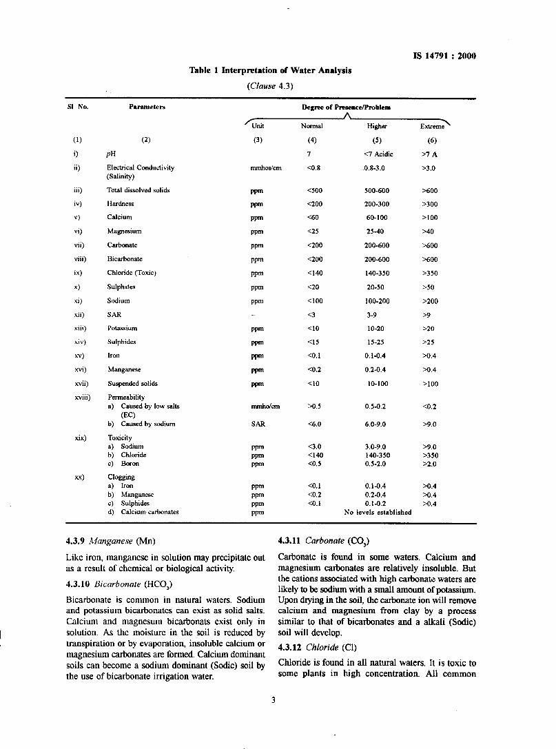
Table 1 Interpretation of Water Analysis
(Clause 4.3)
SI No.
(1)
0 ii)
iii)
iv)
v)
vi)
vii)
viii)
ix)
x)
xi)
xii)
xiii)
xiv)
xv)
xvi)
xvii)
xviii)
xx)
Parameters
(2)
‘unit
(3)
Degree of PresenceIProblem A
Normal Higher
(4) (5)
7 <7 Acidic
<OX 0.8-3.0
Extreme’
(6)
PH
Electrical Conductivity (Salinity)
Total dissolved solids
Hardness
Calcium
Carbonate
Bicarbonate
Chloride (Toxic)
Sulphates
Sodium
SAR
Potassium
Sulphides
iron
Manganese
Suspended solids
Permeability a) Caused by low salts
(EC) b) Caused by sodium
Toxicity a) Sodium b) Chloride c) Boron
Clogging a) Iron b) Manganese c) Sulphides d) Calcium carbonates
llUllhOS/Clll
rw
wm
rw
r-v
Ppm
ppm
ppm
ppm
ppm
ppm
ppm
ppm
ppm
ppm
SAR
ppm Ppm ppm
wm t-v wm t-w
>7 A
23.0
<so0 500-600 >600
<200 200-300 >300
<60 60-100 >lOO
<25 25-40 >40
<200 200-600 >600
<200 200-600 >600
Cl40 140-350 >350
<20 20-50 >50
Cl00 100-200 >200
<3 3-9 >9
<lo 10-20 >20
<I5 15-25 >25
co.1 0.1-0.4 X.4
co.2 0.2-0.4 >0.4
<lo 10-100 >lOO
bO.5 OS-O.2
c6.0 6.0-9.0
c3.0 Cl40 co.5
co.1 co.2 co.1
3.0-9.0 140-350 0.5-2.0
0.1-0.4 0.2-0.4 0.1-0.2
co.2
B9.0
B9.0 >350 B2.0
X.4 BO.4 >0.4
No levels established
4.3.9 Manganese (Mn) 4.3.11 Carbonate (CO,)
Like iron, manganese in solution may precipitate out as a result of chemical or biological activity.
4.3.10 Bicarbonate (HCO,)
Bicarbonate is common in natural waters. Sodium and potassium bicarbonates can exist as solid salts. Calcium and magnesum bicarbonats exist only in solution. As the moisture in the soil is reduced by transpiration or by evaporation, insoluble calcium or magnesium carbonates are formed. Calcium~dominant soils can become a sodium dominant (Sodic) soil by the use of bicarbonate irrigation water.
Carbonate is found in some waters. Calcium and magnesium carbonates are relatively insoluble. But the cations associated with high carbonan: waters are likely to be sodium with a small amount of potassium. Upon drying in the soil, the carbonate ion will remove calcium and magnesium from clay by a process similar to that of bicarbonates and a alkali (Sodic) soil will develop.
4.3.12 Chloride (Cl)
Chloride is found in all natural waters. It is toxic to some plants in high concentration. All common
3

IS 14791 : 2000
chlorides are soluble and contribute to the total salt contents (salinity) of soils.
4.3.13 Sulphate (SO,)
It is abundant in nature. Sodium, magnesium and potassium sulphates are readily soluble. Calcium sulphate has a limited solubility. Sulphate has no characteristic action on the soil except to contribute to the total salt content.
4.3.14 Nitrate (NO,)
Not commonly found in large amounts in naturaI waters. Nitrates contribute slightly to the salinity of soil.
In small amount, it acts as a plant nutrient but high levels indicate excessive use of fertilizers.
4.3.15 Boron (B)
Small amount of Boron is essential for plant growth, but higher concentrations are toxic to plants.
4.3.16 Sulphides
With concentration of more than 0.1 ppm of total sulphides, sulphur bacteria may grow within the irrigation system, forming masses of slime which may clog filters and emitters.
4.3.17 Presence of Oil
Oil or lubricant contamination will cause almost any filter to rapidly plug up. Screens need to be cleaned with a solvent and often sand media must be completely replaced. The solution to oil problem is generally the elimination of oil by skimming it off or by drawing water from lower levels well below the water surface.
5 CHEMICAL TREATMENT DEVICES
Chemicals may be injected into the micro-irrigation systems by the use of injector pumps, venturi suction devices (venturi injector) or difIerential pressure tanks as illustrated in Fig. 1.
INJECTION PUMP
DIFFERE HAL PRESSURE TANK
VENTURI
FIG. I CHEMICAL INJECTION DEVICES
4

5.1 Venturi Injector
Venturi injector shall comply with the requirement of IS 14483 (Part 1). Venturi injectors are useful on smaller systems. They generally have a significant head loss across them, and this limits their use on larger systems.
5.2 Injector Pumps
These are positive displacement pumps of either piston or diaphragm type, which are powered by an external power source such as electric, a portable gasoline engine or hydraulically operated using the pressure of water in the irrigation line. Injection rate can be regulated precisely and chemicals can be injected at constant concentration using the injector pump.
5.3 Differential Pressure Tanks
These are simple and reliable ~devices. They should be used where a gross chemical application is to be undertaken without regard to the concentration of the chemical The rate of concentration decreases with greater outflow of the chemical.
6 BLOCKAGE PROBLEMS IN DRIP IRRIGATION SYSTEM
6.1 Apes of contaminants and other factors leading to blockage problems can be classified as under.
6.1.1 Solid Contaminants
These include soil particles, living or dead organic materials, algae and bacteria slime, seeds and scale from rusty pipes and filters. Any other solid matter such as pieces of polyethylene pipe shavings, rags, teflon tape and insects present in irrigation water which are not adequately filtered out, tend to settle as sediments in the pipe lines and cause plugging of the orifices or emitters.
6.1.2 Dissolved Contaminants - Biological or Chemical Clogging Problem
Calcium carbonate, magnesium carbonate, iron oxide, manganese dioxide which may grow aggregate or precipitate in water as it stands in the lines or evaporates from emitters or orifices between irrigations.
6.1.3 The emitters can become clogged as a result of roots growing into and blocking the dripline orifices or emitters.
6.1.4 Emitter Suck-back
The emitter can become clogged as a result of the fine soil material being sucked-back into dripline/ emitters at the end of an irrigation cycle when the system is draining over a period of time these particles cement together inside the emitter orifice reducing discharge rates and in the extreme blocking the emitter altogether.
IS 14791 : 2000
6.1.5 Physical Blockage of Dripline/Lateral
Soil over-burden, farm machinery traflic, rocks, plant stalks lodging of sugar canes, and roots will tend to pinch the lateral thus blocking or reducing the flow of irrigation water through the lateral or dripline.
6.1.6 Failunz ofMain Filtration System
Selection of improper, rounded poor graded fNration media for sand filter or incorrect mesh size of the screen filter.
6.1.7 Poor Maintenance of the System
Lower frequency and lower etliciency of flushing the submain and the laterals.
6.1.8 Quality of Water See 4.
7 METHOD OF ASSESSMENT OF BLOCKAGE PROBLEM
7.1 Driplines on Ground Surface
When driplines are laid on the surface, the degree of blockage can be checked by means of visual inspection and measuring the amount and uniformity of discharge through the emitters or orifices and comparing it with the specified discharge.
7.2 Dripline Buried Under Ground
When driplines are buried, it is not possible to check individual emitters or orifices by visual inspection and the flow rates in the driplines should be checked by one or more of the following methods:
a)
W
cl
d)
By inserting a pressure gauge into the tail end of the dripline.
By measuring wetted perimeter.
Visual inspection of the field block for uneven growth of crop.
Measurement of discharge.
8 PREVENTION AND TREATMENT OF BLOCKAGE PROBLEM
8.1 Physical ‘Ikeatment
Water sources for micro irrigation include municipal water, reservoirs, rivers, canals and ground water. Solids should be removed to prevent pump wear, emitter plugging, plugging of valves and clogging of pipe lines. As a thumb rule, in case of emitters, all particles greater than one-tenth the minimum flow path dimension of the emitter, shall be removed from the water to prevent emitter plugging by ‘bridging’. Therefore, the filter should remove particles down to 0.03 to 0.18 mm diameter size. For micro sprinklers with large and simple orifices, removal of particles one-seventh the orifice diameter is generally considered suflicient.
5

IS 14791 : 2000
8.1.1 Following types of filtration can be used in micro-irrigation for removal of solids from water.
8.1.1.1 Reservoirs (settling basins)
Reservoirs act as settling basins for sand and silt. However, it has got some disadvantages like, introduction of organic matter, reduction in irrigable land and maintenance problems. They should be used for turbulent surface water sources, such as streams or ditches. Settling basins can also be used in conjunction with aeration to remove iron and other dissolved solids.
8.1.1.2 Pre-screening
Pre-screening removes large contaminates which might cause fouling or excessive back flushing of downstream filters. Rotating conveyer belt type screens, and self cleaning cylindrical screens should be used as pre-cleaners at pump intakes.
8.1.1.3 Hydmcyclone filters
Hydrocyclone filters conforming to IS 14743 should be used. They remove sand and scale and are very effective if sized properly and the flow rates remain relatively constant. Centri.l%gal sand separators remove particles of sizes of 75 microns (200 mesh) or above. They require minimum maintenance. However, they do not remove organic material and head loss across the separators is higher (1.5 to S N/cmz).
8.1.1.4 Media jilters
Media filters conforming to IS 14606 shall be used. In media filters high flow rates are passed through sand tanks to remove large volumes of organic and inorganic contaminates. Sand is sized to provide the required degree of filtration. Automatic or manual back flushing at preset or periodic intervals removes the entrapped suspended impurities which are drained into the effluent water.
8.1.1.5 Screen filters
Screen filters conforming to IS 12785 shall be used. Tubular screens provide low capacity emergency filtration. They should be used as backups to primary fitration devices, or in visually clean water situations. Some screens have an internal vacuum cleaning mechanism that provides frequent and effective cleaning, allowing their use in dirtier situations. The screen sizes may range from 80 to 200 mesh (175 microns to 74 microns). The aperture size of the screen opening should be between one-seventh and one-tenth of the orifice size of the emission devices used.
8.1.1.6 Gravity screen filters
Gravity screens provide high capacity primary filtration. They -are typically self cleaning. Water
cascades on to a very tight fine mesh screen fitted between two chambers. Contaminations are washed to the edge of the screen and the clean water passes through the screen fabric to a lower chamber where it is picked up by a booster pump and delivered to the drip system. The pressure losses across the gravity screen are negligible. These filters should be used in systems where pressure losses are required to be minillliZd.
8.1.1.7 Disc filters
Disc filter is a hybrid between a media tank and a tubular screen. They can be compared with a stack of circular discs, each disc has a cross hatch pattern of grooves of the appropriate depth to provide the required filtration. Water passes between the discs through grooves. These filters with an automatic backflush features are also available.
8.2 Flushing of Irrigation Piping
Mains, sub-mains and laterals should be flushed periodically to remove the settled impurities within the piping system. The flushing water velocity shall be suftlcient (more than 1.2 m&c) to remove the contaminates settled within the pipes. A variety of flush valves and drain valves are available to accomplish this in an efficient way. Flushing should be carried out regularly at an interval of 7 days to 10 days. The impurities present in water during flushing should be observed carefully and flushing should be stopped -when the clean water starts flowing out.
8.3 Chemical Treatment
Chemical treatment is done to control the biological growth bacterial precipitation of iron and sulphur, chemical precipitation of iron, calcium and to inhibit the growth ~of algae and micro-organisms.
A general decrease in flow rates may be the first symptom of potentially major biological or chemical clogging problem within the system. This type of problem is very easy to treat if noticed in early stages of clogging. Partially open clogged emitters or orifices can be treated more effectively with chemicals than the totally blocked emitters or orifices which cannot admit chemicals for desired action.
8.3.1 Bacterial Precipitation of Imn
There are certain forms of bacteria which can produce precipitation of insoluble ferric oxide by oxidizing soluble ferrous oxide. This could occur with iron concentration as low as 0.1 ppm. The iron precipitate forms as a red filaments sludge which can attack to PVC and polyethylene tubing and may completely block emitters.
To prevent the bacterial precipitation of iron, chlorination should be performed continuously at the
6

rate of 1 ppm free available chlorine or intermittently at the rate of 10 to 20 ppm for 30 to 60 minutes daily.
In case of well water, superchlorination of well should be done by injecting 200 to 500 ppm chlorine based on estimated volume of water quantity in the well to reduce the problem.
8.3.2 Bacterial Precipitation of Sulphur
Bacteria can produce an organic sulphur slime if the water contains more than 0.1 ppm of total sulphides. These bacteria produce white cottony masses of slime which may completely block the emitting devices.
Problems can also be created by iron and sulphur interactions and precipitation of iron sulphide on stainless steel filter screen if the concentration of sulphides is high in water. Insoluble iron sulphides are formed by chemical reaction between dissolved iron and sulphides.
Sulphur slime bacteria should be controlled by intermittent chlorination at 1 ppm of free chlorine, as measured in the field, for 30 to 60 minutes on daily basis.
8.3.3 Chemical Precipitation of Iron
Any dissolved iron in water is generally found in the ferrous form as ferrous oxide. Once the water is in the irrigation system, the conditions are favourable for precipitation of iron particularly between irrigation cycles. Even at 0.1 ppm level of iron the precipitation may be accelerated by injection of unchelated phosphates or calcium salts.
The problem of chemical precipitation of iron can be controlled by removing the iron from the water or by retaining the iron in solution. For this purpose following techniques are recommended.
8.3.3.1 Aeration and settling
This system operates by thoroughly aerating the water on entry to settling basin. The device such as sprayer allows the incorporation of large amounts of oxygen into the water, which oxidizes the ferrous oxide to ferric oxide. The ferric oxide precipitates out of the water and settles down to the bottom of the basin, provided suflicient settling time is allowed.
Pumping from well with iron bearing water shall need double pumping without corresponding higher energy costs because the total head remains the same.
8.3.3.2 Chlorine precipitation
Free chlorine instantly oxidizes ferrous oxide to ferric oxide which then precipitates out of solution. The chlorine mixing should be thorough and precipitation should be completed prior to filtration of water through a sand media filter with automatic backwash system.
IS 147911 2000
One ppm of free chlorine is injected for each 0.7 ppm of iron and some additional chlorine is required to kill any iron bacteria and to control the growth of bacteria slime. Chlorination precipitation is more expensive than aeration process and should be considered as a second choice where aeration is not feasible.
NOTE - Ifmanganese is present along with iron, thk precipitation of manganese is slower than that of iron and it may precipitate alter filter which results in clogging problems in the system.
8.3.3.3 pH control
Iron is more soluble at lower pH values. Acid may be injected to maintain the iron in solution or may be used to periodically dissolve iron sediments which have built up over a period of time. The pH should be reduced to 4 or less for a period of 30 to 60 minutes. This dissolves the iron and flushes it from the system.
8.4 Precipitation of Calcium Salts
The calcium precipitation is common with most of the waters and appears as a white scale for plating on the inner surfaces of the system. This problem can be easily corrected by injection of acid at a rate such that the pH is lowered to less than 4 for between 30 to 60 minutes This shah be done before total blockage of the emitters occurs.
The acid used for treatment may be commercial grade hydrochloric acid @ICI) 33 to 35 percent, sulphuric acid @SO,) 70 percent, nitric acid (HNO,) 60 percent and phosphoric acid (H_,PO,) 85 percent strength. Crops like grape and strawberries are sensitive to chlorides and hence acids other than HCl should be used.
8.5 Algae Control
If Ca” + Mg” is less than 5 ppm, copper sulphate should be injected otherwise chlorine should be injected to control various types of algae. The doses of copper sulphate vary from 0.07 ppm to a maximum of 5 ppm depending upon the type of algae. For chlorination, the doses range from 0.3 to 2 ppm. However, a standard dose of copper sulphate of 1.2 ppm is recommended for all types of algae. Smaller amounts are often sufficient as prophylactic doses to prevent trouble. Use of copper sulphate is hazardous for human and animal life, as this water should not be consumed by them. It should be carried out in presence of skilled and knowledgeable persons.
8.6 Emitter Clogging by Roots
Blockages caused by the roots growing into emitters and orifices can be prevented by the regular application of a root inhibitor such as trifluralin at a rate of 0.1 ml per emitter or orifice. The first application should be made of 4 to 6 weeks after planting. Subsequent applications should be made at an interval of 4 to 6 months.
7

The emitter suckback can be reduced by following ways:
a)
b)
c)
Ensuring that the field main is at the same level or higher than the driplines as this enables air to enter the driplines from the air relief valve on the riser,
Leaving the first 2 or 3 emitters of a dripline above ground so that they can act as air relief valves when the system is draining,
Adding of air release valve (double action), and
d) Installation of non-return valve at appropriate location.
IS 14791 : 2000
Root inhibitors such as trifluorine can be used to protect surface emitters against root intrusion. Root inhibitors are fused into the emitters during the manufacturing process which protects drip system for a long time.
8.7 Emitter Suckback
8.8 Failure of Main Filtration
Media filter, screen filter or back-up filters may get damaged due to excessive pressure build up and a puncture may develop. The sand media or contaminates in that case would travel through the pipe lines and laterals and block the system. It would be necessary to repair or replace the defective filter and clean up the system by flushing and cleaning the drippers.
8.8.1 Selection of improper, rounded, poorly graded filtration media or incorrect mesh size or too coarse a sand will result in poor filtration and lead to clogging of irrigation system. The sand used as filtration media should be clean, coarse, sharp edged and free from excessive fines. A uniformity coefficient should be close to 1.5 which is considered good. The higher mesh size of the screen filter allows organic and inorganic contaminates to pass and clog the system. To solve this problem proper type of filter that gives the desired quality of filtered water should be selected. The particle size of contaminate that passes through the water should not be greater than one-seventh to one-tenth that of opening size of the emitter or orifice.
8.9 Poor Maintenance of the System
Conscientious and regular system maintenance is a vital part of the drip irrigation system management. The drip irrigation systems tend to fail dramatically when not maintained correctly.
8.9.1 Filters
Filters should be checked visually for leaks and the clarity of water that has passed through the filters should be inspected regularly. Sand level should also be checked and maintained.
B.9.2 Chemical Injector Maintenance
All injection equipment should be cleaned or flushed when not in use, as most of the chemicals that are injected into drip systems are corrosive. Injection rate should be verified at regular intervals.
B.9.3 Distribution System
All pipelines and driplines should be flushed once in 7 days to 10 days or after repairs are made to avoid extraneous material entering the driplines. Discharge through the laterals and drippers should be checked at least once in three months in the initial stages and close watch should be exercised on the uniformity of growth of the plantations and signs of leakages or breakages of the pipe lines, check pressures in the lines.
9 CHEMICAL TREATMENT
9.1 Chlorine Treatment
Chlorination of irrigation water used for drip irrigation is required to help prevent the agglomeration of fine organic and inorganic particles with bacterial byproducts. A chlorination treatment programme is regulated by the severity of the plugging problem. Weekly or even bi-weekly treatments may have to be employed depending on ‘he severity. In or&r to obtain optimum results the cl lorine must be injected at the right concentration for the required interval of time.
9.1.1 In order to have effective chlorination following points should be considered when installing and operating a chlorination unit:
a)
b)
cl
d)
The duration of chlorine setling inside the irrigation system is more important than concentration.
The maximum chlorine concentration injected should not exceed 20 ppm. Concentration exceeding 20 ppm may precipitate solids that could plug drippers.
Chlorine should always be injected before the screen filter (strainer filter) so that any precipitates can be filtered out of the water.
Chlorine is commercially available in the following forms:
1) Liquid - Sodium hypochlorite (NaOCL)
2) Solid granules - Calcium hypochlorite
QuGCl),
3) Gas - Gaseous chlorine (Cl, )
Sodium hy-pochlorite is a better source of chlorine for chlorinate of drip system. Use of calcium hypochlorite is not recommended if the irrigation water already contains a high concentration of Ca (in excess of 20 ppm). Gaseous chlorine sources are expensive and di.tEcult to obtain and apply and normally not used for treatment of irrigation water.
8

9.1.2 Calculating the Amount to Inject
9.1.2.1 Chlorine in liquid form - Sodium hypochlorite
Commercial sodium hypochlorite (common bleach) has 12 percent available chlorine but can also be made available in 16 percent or 18 percent. Calcium hypochlorite is available with 70 percent chlorine but it is in granular form and therefore required pre- mixing. The formula to calculate the injection rate of the chlorine solution is as follows:
x= QVCw loooqcb
where
x =
Q = 9 = v = cw =
c, =
Quantity of bleach (kg/h) or liquid in l/h for the same concentration,.
Discharge of system in l/h,
Output of injection device in l/h,
Volume of tank in litres,
Desired concentration of chlorine in irrigation water, ppm, and
Concentration of chlorine in the bleach in percentage.
9.1.2.2 Chlorine in gaseous form (100 percent available Cl,)
The injection rate of chlorine gas shall be determined by using following formula:
s=QC where
4 = Injection rate in l/h,
Q = System flow rate in l/s, and
C = Chlorine concentration in ppm.
9.1.2.3 Chlorine in solid form - Calcium hypochlorite Ca (OCl),
It is available commercially as a ‘bleaching powder’ or as granules. Around 65 percent chlorine is available from calcium hypochlorite. A stock solution of the desired strength may be mixed and used in the same manner as sodium hypochlorite solutions. Quantity of solid chlorine shall be determined by following formula:
360 Q C 4=
S
where
4 Q :
c =
s =
Injection rate in l/h,
System flow rate in l/s,
Chlorine concentration in ppm, and
Available free chlorine in percent.
IS 14791 : 2000
9.1.3 Time ofApproach of Chlorine at the Farthest Point
The time that the chlorine solution takes to reach the end of the dripline of the field or block to be chlorinated shall be established by injecting a coloured solution and noting the time it takes to reach the last emitter farthest from the injection point, whereas the volume of chlorinated water is established by calculating the injection rate multiplied by time of application.
9.2 Acid Treatment
Adding acid to the irrigation water will lower the pH and reduce the amount of chemical precipitates. If a sodium hypochlorite is used for chlorination of water that has pH value of 8.0 or higher, acid should be used simultaneously to keep the pH value in the 7.0 to 8.0 range.
The pH level is also important for bacterial control as the active component in chlorination is more abundant at lower pH values.
For acid treatment either hydrochloric acid or sulphuric acid is used. Commercial grade hydrochloric acid (HCL) is available in the market having concentration of 36 percent. Commercially grade sulphuric acid ( Y SO,) is available with 95 percent concentration. All acids are hazardous and should be used very carefully under all possible protection. ‘ALWAYS ADD ACID TO WATER AND NEVER ADD WATER TO ACID’.
The concentration of acid in water shall not be more than 2 percent.
9.2.1 Recommended Procedure for Acid Treatment
a)
b)
cl
d)
e)
9
Test a flow rate of at least 25 drippers on one submain. If the variation in discharge is found more than 10 percent of that of designed flow rate, then acid treatment is required.
Observe the orifice of dripper carefully and check the accumulation of saltsor precipitates at orifice and-surface of ground. If it is found then acid treatment is required.
Refer the water analysis report and as per the recommendation from laboratory use the right type and concentration of acid to be injected.
Set the injection device and set the desired injection rate on the basis of average discharge rate and pressure for first 20 minutes (Desired injection rate has to be fixed by water only.).
After setting the injection rate prepare a stock solution of acid in the containers of non- corrosive material.

IS 14791 : 2000
f)
la
$1
j) W
ml
Start the injection device and inject the stock solution (acidic water) into the system.
After 20 min check the pH value of water of the last dripper with the help of pH paper.
Repeat the same procedure until you get 4 pH at the last dripper.
Then shutdown the system for 24 hours.
On next day open the flush valves and lateral ends, start the system and allow the accumulated acidic water and salts in the system to flush out.
Also allow the system to run 30 minutes at beginning, so that concentrated acidic water in soil gets diluted.
9.2.2 Quantity of Acid to be Injected
Quantity of acid to be injected shall be determined by the following formula:
Acid required corresponding to the equivalent acid factor for 1 000 1 of water Ql) in ml x Volume of-water inside the pipe line to be acidified (B) in ml
Total acid required = (C) in litres 1~000 000
where
A is determined from Table 2,
B is calculated on the basis of length and internal diameter of the complete piping system.
9.2.3 Interval and Duration
9.2.3.1 Interval of acid treatment depends on the concentration of salts in water.
9.2.3.2 Duration of treatment has to be decided practically until pH is reduced to 4 at the last end dripper.
9.2.4 Dosage Period
Water travels about 1 m every 3 seconds through drip system while doing chemigation. To ensure that the entire system is treated, divide the maximum distance of the piping from the chemigation point in m by 20. This gives the minimum dosage time in minutes.
9.2.5 Other Requirements
a)
b)
After the treatment do not inject any type. of fertilizers into the system. Fertilizer should be applied on next day or after completion of irrigation.
Chlorine and acid treatment should not be performed at the same time. They should be gap of at least two weeks of system use.
Table 2 Acid Requirement for Each 1 000 litre of Water
(Clause 9.2.2)
Acid Factor’)
2
4
6
8
10
15
20
25
30
H,SO, (95 Percent) HCL (36 Percent) Phosphoric Acid (85 Percent)”
W) W) (mu
55 165 530
110 340 1 060
165 500 1 590
220 670 2 120
280 840 2 650
415 1 280 3 975
555 1 670 5 300
700 2 090 6 625
840 2 510 7 590
‘) Acid factor = milliequivalent (meq) of acid required per litre of water to lower pH to 2 as determined by laboratory titration of water.
*) Phosphoric acid is a weak acid and quantities required are very high and it may not be economically feasible to use this acid for flushing
unless it is otherwise used as a fettilii.
10

IS 14791 : 2000
10.6 Tank cover of the differential pressure tank should not be opened while in operation.
10.7 Irrigation water should not be used for consumption by human beings and animals.
10.8 Do not inhale acid fumes or chlorine gas.
10.9 All chemicals-should be handled cautiously and should be stored in a secured place for the reasons of safety and hazardous nature of the products.
10.10 The suitability -of any chemical treatment to be ascertained and guarded against any adverse effect onthe standing crop or soil.
10.11 Use copious water for washing acid burns.
10 SAFETY REQUIREMENTS
10.1 Protective devices on chemical injection equipment should be provided to prevent contamination of the water supply and accidental spillage of the chemicals.
10.2 All acids should be handled with care. Protective glass and gloves should be used to protect eyes and to prevent skin contact.
10.3 The resistance of drip irrigation components to the chemical used should be taken into consideration.
10.4 Acid shall be added in water and not water into acid for dilution.
10.5 Acid treatment and chlorine treatment shall not be carried out simultaneously.
11

Bureau of Indian Standards
BIS is a statutory institution established under the Bureau of Zndian Standards Act, 1986 to promote harmonious development of the activities of standardization, marking and quality certification of goods and attending to connected matters in the country.
Copyright
BIS has the copyright of all its publications. No part.of these publications may be reproduced in any form without the prior permission in writing of BIS. This does not preclude the free use, in the course of implementing the standard, of necessary details, such as symbols and sizes, type or grade designations. Enquiries relating to copyright be addressed to the Director (Publications), BIS.
Review of Indlan Standards
Amendments are issued to standards as the need arises on the basis of comments. Standards are also reviewed periodically; a standard along with amendments is reaffirmed when such review indicates that no changes are needed; if the review indicates that changes are needed, it is taken up for revision. Users of Indian Standards should ascertain that they are in possession of the latest amendments or edition by referring to the latest issue of ‘BIS Catalogue’ and ‘Standards: Monthly Additions’.
This Indian Standard has been developed from Dot : No. ! FAD 54 (881).
Amepdments Issued Since Publication
Amend No. Date of Issue Text Affected
BUREAU OF INDIAN STANDARDS
Headquarters :
Manak Bhavan, 9 Bahadur Shah Zafar Marg, New Delhi 110 002 Telegrams : Manaksanstha Telephones : 323 01 31,323 33 75,323 94 02 (Common to all offices)
Regional Offices : Telephone
Central : Manak Bhavan, 9 Bahadur Shah Zafar Marg NEW DELHI 110 002
( 323 76 17 323 38 41
Eastern : l/14 C. I. T. Scheme VII M, V. I. P Road, Kankurgachi 337 84 99,337 85 61 CALCUTTA 700 054 337 86 26,337 91 20
Northern : SC0 335336, Sector 34-A, CHANDIGARH 160 022 { 60 38 43 60 20 25
Southern : C. I. T. Campus, IV Cross Road, CHENNAI 600 113 { 235 02 16,235 04 42 235 15 19,235 23 15
Western : Manakalaya, E9 MIDC, Marol, Andheri (East) { 832 92 95,832 78 58 MUMBAI 400 093 832 78 91,832 78 92
Branches : AHMADABAD. BANGALORE. BHOPAL. BHUBANESHWAR. COIMBATORE. FARIDABAD. GHAZIABAD. GUWAHATI. HYDERABAD. JAIPUR. KANPUR. LUCKNOW. NAGPUR. PATNA. PUNE. RAJKOT. THIRUVANANTHAPURAM.
Printed at‘ c.Rahhat Offset Press, New Delhi-2