isa100 intrinsically safe wireless pressure sensor
TRANSCRIPT
Datasheet
ISA100 Intrinsically Safe Wireless Pressure SensorIS-WPS Series
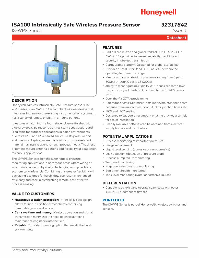
DESCRIPTIONHoneywell Wireless Intrinsically Safe Pressure Sensors, IS-WPS Series, is an ISA100.11a-compliant wireless device that integrates into new or pre-existing instrumentation systems. It has a variety of remote or built-in antenna options.
It features an aluminum alloy metal enclosure finished with blue/grey epoxy paint, corrosion-resistant construction, and is suitable for outdoor applications in harsh environments due to its IP65 and IP67 sealed enclosure. Its pressure port and pressure diaphragm are made with corrosion-resistant material making it resilient to harsh process media. The direct or remote-mount antenna options add flexibility for adaptation to various applications.
The IS-WPS Series is beneficial for remote pressure monitoring applications in hazardous areas where wiring or wire maintenance is physically challenging or impossible or economically infeasible. Combining this greater flexibility with packaging designed for harsh-duty can result in enhanced efficiency and ease in establishing remote, cost-effective process sensing.
VALUE TO CUSTOMERS• Hazardous location protection: Intrinsically safe design
allows for use in certified atmospheres containing flammable gases and vapors
• Can save time and money: Wireless operation and signal transmission minimizes the need to physically send maintenance engineers into the field
• Reliable: Consistent sensing option that meets the harsh environments
FEATURES• Radio (license-free and global): WPAN 802.15.4, 2.4 GHz,
ISA100.11a provides increased reliability, flexibility, and security in wireless transmission
• Configurable platform: Designed for global availability• Provides a Total Error Band (TEB) of ±2.0 % within the
operating temperature range• Measures gage or absolute pressure ranging from 0 psi to
500psi through 0 psi to 15,000psi • Ability to reconfigure multiple IS-WPS series sensors allows
users to easily add, subtract, or relocate the IS-WPS Series sensor
• Over-the-Air (OTA) provisioning• Can reduce costs: Minimizes installation/maintenance costs
because there are no wires, conduit, clips, junction boxes etc.• IP65 and IP67 sealing• Designed to support direct mount or using bracket assembly
for easier installation• Readily available batteries can be obtained from electrical
supply houses and distributors
POTENTIAL APPLICATIONS• Process monitoring of important pressures• Gauge replacement• Liquid level sensing (corrosive or non-corrosive)• Leak detection (detection of pressure drop)• Process pump failure monitoring• Well head monitoring• Irrigation water pressure monitoring• Equipment health monitoring• Tank level monitoring (water or corrosive liquids)
DIFFERENTIATION• Capable to co-exist and operate seamlessly with other
ISA100.11a-compliant devices
PORTFOLIOThe IS-WPS Series is part of Honeywell’s wireless switches and sensors.
Safety and Productivity Solutions
32317842Issue 1
2 sensing.honeywell.com
ISA100 Intrinsically Safe Wireless Pressure Sensor, IS-WPS Series
Table 1. SpecificationsCharacteristic ParameterSeries name IS-WPS Series
Product type ISA100.11a Intrinsically Safe Wireless Pressure Sensor
Pressure ranges# 0 psi to 500 psi, 0 psi to 5000 psi, 0 psi to 10000 psi, 0 psi to 15000 psi (gage or absolute)
Housing material Aluminum alloy, finished with blue/grey epoxy paint
Housing type Metal, Intrinsically Safe, with process port connections
Operating frequency 2.4 GHz radio (ISM)
Wireless standard RF Code B: ISA100.11a Compliant; IEEE 802.15.4, 2.4 GHz Global License Free Band
Communication agency approvals/certificates*
16 dBm: FCC 15.247, Industry Canada RSS 210 Issue 8, ACMA, C-Tick Mark Conformity8 dBm: ETSI EN 300 328 V1.8.1 (CE Mark)
Antenna connection/type RP-SMA jack for direct mount or remote antenna options; omni-directional antenna standard
Weight 1,75 kg ±100 g
Signal range1000 ft** [305 m]** clear line of sight between sensor and receiver when using 2.0 dBi integral field sensor antenna
Battery type3.6 Vdc Lithium Thionyl Chloride; D Size, Quantity: 2; Recommended manufacturers: XENO Energy (P/N XL-205F), Honeywell (P/N: WBT5)
Data rate 250 kbps
Provisioning method Over-the-Air (OTA)
RF module transmit power Country Code A: 16 dBm max.; Country Code B: 8 dBm max.
Receive sensitivity -98 dBm
Radome material Polybutylene Terephthalate (PBT), Color: Black
Pressure port material Stainless Steel 316L or 15-5PH SS or Crucible A-286
Process connection1/2 in NPT male and 1/4 in NPT female3/4 in NPT male and 1/4 in NPT female1/4 in NPT female, 9/16-18 UNF female
Diaphragm material Hastelloy® C276 or 15-5PH SS or Crucible A-286
Housing/wetted parts Aluminum alloy metal enclosure/ Hastelloy® C276 or 15-5PH SS or Crucible A-286 diaphragm
Intrinsically safe battery pack Honeywell P/N: WBT8
Sealing IP65, IP67 (self certified by Honeywell)
cULus listing Class I, Div I, Groups A, B, C, D T4Class I, Zone 1 AEx ia IIC T4 GaClass I, Zone 1 Ex ia IIC T4 Ga
Class I, Zone 0 AEx ia IIC T4 GaClass I, Zone 0 Ex ia IIC T4 GaTambient -40° C to +70 C°
ATEX certification Zone 1 Ex ia IIC T4 Ga; Zone 0 Ex ia IIC T4 Ga
IEC Ex certification Zone 1 Ex ia IIC T4 Ga; Zone 0 Ex ia IIC T4 Ga
EMC Applicable standards: EN 300 328, V1.8.1; EN 61326-1 (2006); EN 301 489-1, EN301 489-17, V2.1.1
Shock 40 g per IEC 60068-2-27
Vibration 5 Hz to 200 Hz, 4 g, Sinusoidal per IEC 60068-2-6
Operating temperature -40 °C to 70 °C [-40 °F to 158 °F]
Operating humidity 0 %RH to 100 %RH
Total Error Band (TEB) ±2 %FSS for > 50 psi
Sensor output resolution 0.04 %FS
Periodic update interval Field programmable rate: 1, 5, 30, or 60 second intervals
Battery life (P2P protocol) 6 years at 60 sec interval, 5 years at 5 sec interval, 2 years at 1 sec interval (At 25 °C [77 °F])
Battery location Intrinsically safe battery pack inside base unit
Output Digital output via wireless, end user configurable as psi, bar, kPa and Pa, local LCD variant also available
Measurement accuracy Better than ±2.0 % Total Error Band (TEB), full scale, full temperature range. Example 100 psi is ±2 psi
Media isolated Yes
Overload safe pressure 4X FS for 500 psi; 15,000 psi for 5K psi; 1.5X for ≥10,000 psi
Burst pressure 3000 psi for < 1000 psi; 15000 psi for 5000 psi; 26000 psi for 10,000 psi; 40000 psi for 15,000 psi
* Honeywell is continuing to add new Country Communication Agency Approvals as opportunities and requirements are established.**Actual range will vary depending upon antennas, cables, and site topography.# Pressure ranges >1000 psi support only gage variant.
Safety and Productivity Solutions 3
ISA100 Intrinsically Safe Wireless Pressure Sensor, IS-WPS Series
Table 2. Battery PackSpecificationsCharacteristic Parameter
Intrinsically Safe Battery Pack part number
WBT8
Non IS Honeywell part number WBT5 (two batteries included)
Battery size Size D (ER32L615)
Battery type Lithium Thionyl Chloride
Nominal capacity @ 4 mA, up to 2 V 19 Ah
Nominal voltage 3.6 V
Max. recommended continuous current
230 mA
Max. recommended pulse current 500 mA
Weight 97 g [3.4 oz] max.
Operating temperature -55 °C to 85 °C [-67 °F to 185 °F]
Storage temperature 30 °C
Suggested alternate sources of battery cell supply
Xeno Energy (part number XL-205F)
Note: For shipping purposes, two “D” sized Lithium Thionyl Chloride cells contain approximately 10 grams of lithium.
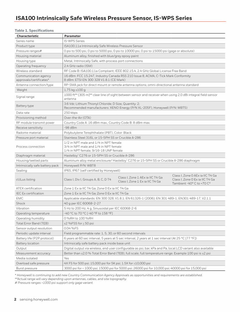
Figure 1. Limitless™ Wireless Pressure Sensor, IS-WPS Series, Connection Type 1 & 2 Dimensions
239 mm ±2 mm[9.41 in ±0.08 in]
154 mm ±2 mm[6.02 in ±0.08 in]
98 mm ±1 mm[3.86 in ±0.04 in]
45 mm [1.77 in]across �at
120,5 mm ±1 mm[4.74 in ±0.04 in]
31,75 mm [1.25 in]hex
4 sensing.honeywell.com
ISA100 Intrinsically Safe Wireless Pressure Sensor, IS-WPS Series
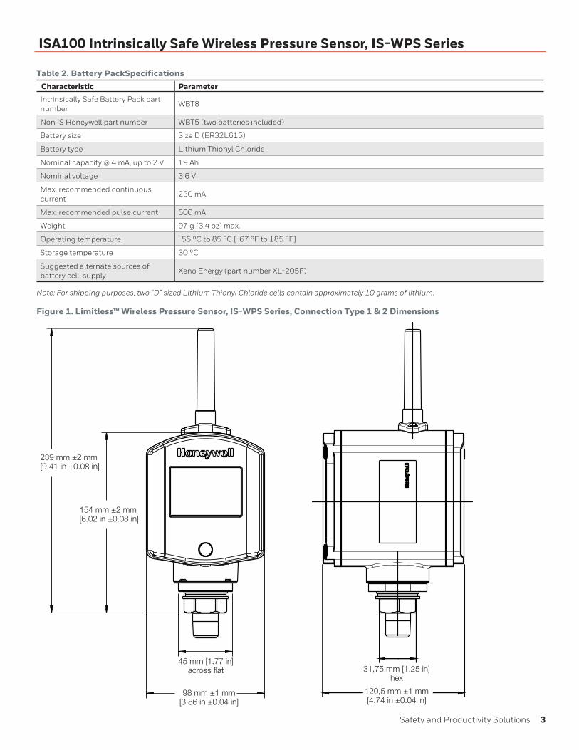
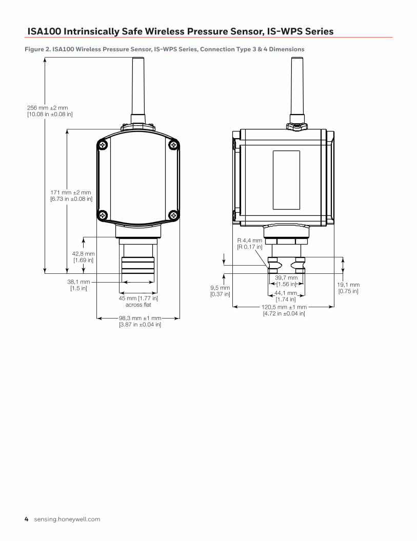
Figure 2. ISA100 Wireless Pressure Sensor, IS-WPS Series, Connection Type 3 & 4 Dimensions
256 mm ±2 mm[10.08 in ±0.08 in]
45 mm [1.77 in]across at
98,3 mm ±1 mm[3.87 in ±0.04 in]
171 mm ±2 mm[6.73 in ±0.08 in]
42,8 mm[1.69 in]
38,1 mm[1.5 in] 9,5 mm
[0.37 in]
120,5 mm ±1 mm[4.72 in ±0.04 in]
19,1 mm[0.75 in]44,1 mm
[1.74 in]
39,7 mm[1.56 in]
R 4,4 mm[R 0.17 in]
Safety and Productivity Solutions 5
ISA100 Intrinsically Safe Wireless Pressure Sensor, IS-WPS Series
PRODUCT NOMENCLATURE
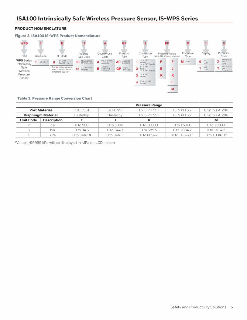
Figure 3. ISA100 IS-WPS Product Nomenclature
A US, Canada,Mexico
WPS
Type
A
Country Use Code
A US, Canada,Australia
GP
PressureType
WPS SeriesIntrinsically
SafeWirelessPressureSensor
1
Gen Code
B
RF Code
1 Version 1 B2.4 GHzISA100.11a
12
12
00 No antenna; RP-SMA jack
2.0 dBi omni antenna
Antenna Type Code
AP Absolute pressure
GP Gagepressure
1
ConnectionType
11/2 in NPTmale & 1/4 in NPT female
2
PF
Pressure Range(refer to Table 3: Pressure range chart)
F
J
K
L
M
1
Display
0 NoLCD
X
ProtectionCode
1 withLCD
P
B
K
M
EnclosureType
M Metal
BAll otherapprovedcountries
XIntrinsicallysafe,Zone I
For “A” coded versions,refer to WPS Limitless™datasheet, 32317841.
3 1/4 in NPTfemale
4 9/16-18 UNFfemale
3/4 in NPTmale & 1/4 in NPT female
YIntrinsicallysafe,Zone 0
Table 3. Pressure Range Conversion Chart
Pressure RangePort Material 316L SST 316L SST 15-5 PH SST 15-5 PH SST Crucible A-286
Diaphragm Material Hastelloy® Hastelloy® 15-5 PH SST 15-5 PH SST Crucible A-286Unit Code Description F J K L M
P psi 0 to 500 0 to 5000 0 to 10000 0 to 15000 0 to 15000B bar 0 to 34.5 0 to 344.7 0 to 689.5 0 to 1034.2 0 to 1034.2K kPa 0 to 3447.4 0 to 34473 0 to 68947 0 to 103421A 0 to 103421A
A Values >99999 kPa will be displayed in MPa on LCD screen
6 sensing.honeywell.com
ISA100 Intrinsically Safe Wireless Pressure Sensor, IS-WPS Series
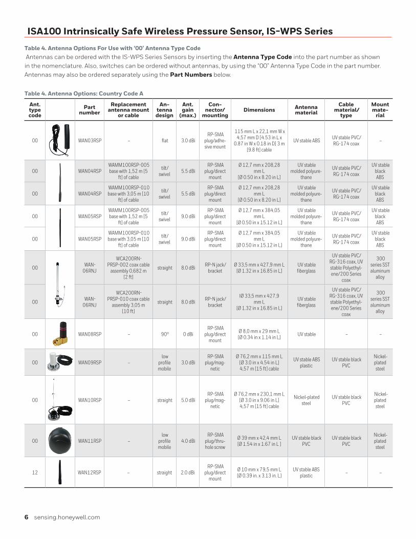
Table 4. Antenna Options For Use with ‘00’ Antenna Type Code Antennas can be ordered with the IS-WPS Series Sensors by inserting the Antenna Type Code into the part number as shown in the nomenclature. Also, switches can be ordered without antennas, by using the “00” Antenna Type Code in the part number. Antennas may also be ordered separately using the Part Numbers below.
Table 4. Antenna Options: Country Code A
Ant.type code
Part number
Replacement antenna mount
or cable
An-tenna design
Ant. gain
(max.)
Con-nector/
mountingDimensions Antenna
materialCable
material/type
Mount mate-
rial
00 WAN03RSP – flat 3.0 dBi RP-SMA
plug/adhe-sive mount
115 mm L x 22,1 mm W x 4,57 mm D [4.53 in L x
0.87 in W x 0.18 in D] 3 m [9.8 ft] cable
UV stable ABS UV stable PVC/ RG-174 coax –
00 WAN04RSP WAMM100RSP-005 base with 1,52 m [5
ft] of cable
tilt/swivel 5.5 dBi
RP-SMA plug/direct
mount
Ø 12,7 mm x 208,28 mm L
[Ø 0.50 in x 8.20 in L]
UV stable molded polyure-
thane
UV stable PVC/ RG-174 coax
UV stable black ABS
00 WAN04RSP WAMM100RSP-010 base with 3,05 m [10
ft] of cable
tilt/swivel 5.5 dBi
RP-SMA plug/direct
mount
Ø 12,7 mm x 208,28 mm L
[Ø 0.50 in x 8.20 in L]
UV stable molded polyure-
thane
UV stable PVC/ RG-174 coax
UV stable black ABS
00 WAN05RSP WAMM100RSP-005 base with 1,52 m [5
ft] of cable
tilt/swivel 9.0 dBi
RP-SMA plug/direct
mount
Ø 12,7 mm x 384,05 mm L
[Ø 0.50 in x 15.12 in L]
UV stable molded polyure-
thane
UV stable PVC/ RG-174 coax
UV stable black ABS
00 WAN05RSP WAMM100RSP-010 base with 3,05 m [10
ft] of cable
tilt/swivel 9.0 dBi
RP-SMA plug/direct
mount
Ø 12,7 mm x 384,05 mm L
[Ø 0.50 in x 15.12 in L]
UV stable molded polyure-
thane
UV stable PVC/ RG-174 coax
UV stable black ABS
00 WAN-06RNJ
WCA200RN-PRSP-002 coax cable
assembly 0,682 m [2 ft]
straight 8.0 dBi RP-N jack/ bracket
Ø 33,5 mm x 427,9 mm L [Ø 1.32 in x 16.85 in L]
UV stable fiberglass
UV stable PVC/RG-316 coax, UV stable Polyethyl-ene/200 Series
coax
300 series SST aluminum
alloy
00 WAN-06RNJ
WCA200RN-PRSP-010 coax cable
assembly 3,05 m [10 ft]
straight 8.0 dBi RP-N jack/ bracket
IØ 33,5 mm x 427,9 mm L
[Ø 1.32 in x 16.85 in L]
UV stable fiberglass
UV stable PVC/RG-316 coax, UV stable Polyethyl-ene/200 Series
coax
300 series SST aluminum
alloy
00 WAN08RSP – 90° 0 dBi RP-SMA
plug/direct mount
Ø 8,0 mm x 29 mm L [Ø 0.34 in x 1.14 in L] UV stable – –
00 WAN09RSP – low
profile mobile
3.0 dBi RP-SMA
plug/mag-netic
Ø 76,2 mm x 115 mm L [Ø 3.0 in x 4.54 in L] 4,57 m [15 ft] cable
UV stable ABS plastic
UV stable black PVC
Nickel-plated steel
00 WAN10RSP – straight 5.0 dBi RP-SMA
plug/mag-netic
Ø 76,2 mm x 230,1 mm L [Ø 3.0 in x 9.06 in L] 4,57 m [15 ft] cable
Nickel-plated steel
UV stable black PVC
Nickel-plated steel
00 WAN11RSP – low
profile mobile
4.0 dBi RP-SMA
plug/thru-hole screw
Ø 39 mm x 42,4 mm L [Ø 1.54 in x 1.67 in L ]
UV stable black PVC
UV stable black PVC
Nickel-plated steel
12 WAN12RSP – straight 2.0 dBi RP-SMA
plug/direct mount
Ø 10 mm x 79,5 mm L [Ø 0.39 in. x 3.13 in. L]
UV stable ABS plastic – –
Safety and Productivity Solutions 7
ISA100 Intrinsically Safe Wireless Pressure Sensor, IS-WPS Series
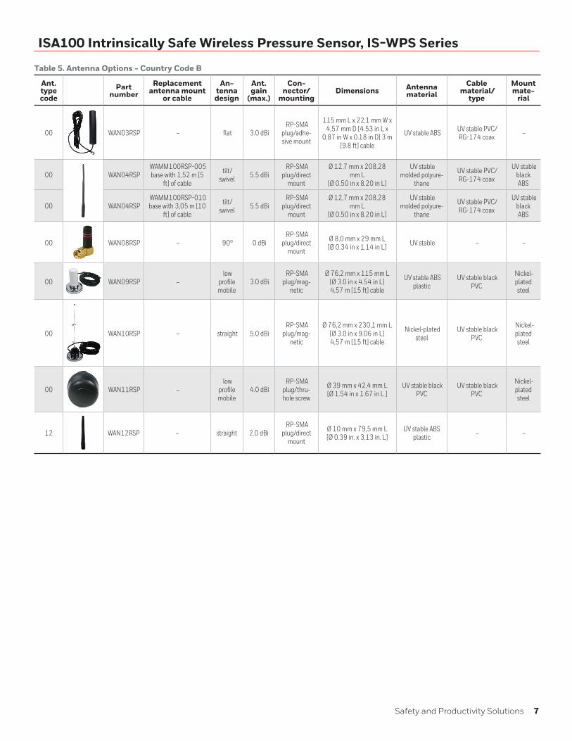
Table 5. Antenna Options - Country Code B
Ant.type code
Part number
Replacement antenna mount
or cable
An-tenna design
Ant. gain
(max.)
Con-nector/
mountingDimensions Antenna
materialCable
material/type
Mount mate-
rial
00 WAN03RSP – flat 3.0 dBi RP-SMA
plug/adhe-sive mount
115 mm L x 22,1 mm W x 4,57 mm D [4.53 in L x
0.87 in W x 0.18 in D] 3 m [9.8 ft] cable
UV stable ABS UV stable PVC/ RG-174 coax –
00 WAN04RSP WAMM100RSP-005 base with 1,52 m [5
ft] of cable
tilt/swivel 5.5 dBi
RP-SMA plug/direct
mount
Ø 12,7 mm x 208,28 mm L
[Ø 0.50 in x 8.20 in L]
UV stable molded polyure-
thane
UV stable PVC/ RG-174 coax
UV stable black ABS
00 WAN04RSP WAMM100RSP-010 base with 3,05 m [10
ft] of cable
tilt/swivel 5.5 dBi
RP-SMA plug/direct
mount
Ø 12,7 mm x 208,28 mm L
[Ø 0.50 in x 8.20 in L]
UV stable molded polyure-
thane
UV stable PVC/ RG-174 coax
UV stable black ABS
00 WAN08RSP – 90° 0 dBi RP-SMA
plug/direct mount
Ø 8,0 mm x 29 mm L [Ø 0.34 in x 1.14 in L] UV stable – –
00 WAN09RSP – low
profile mobile
3.0 dBi RP-SMA
plug/mag-netic
Ø 76,2 mm x 115 mm L [Ø 3.0 in x 4.54 in L] 4,57 m [15 ft] cable
UV stable ABS plastic
UV stable black PVC
Nickel-plated steel
00 WAN10RSP – straight 5.0 dBi RP-SMA
plug/mag-netic
Ø 76,2 mm x 230,1 mm L [Ø 3.0 in x 9.06 in L] 4,57 m [15 ft] cable
Nickel-plated steel
UV stable black PVC
Nickel-plated steel
00 WAN11RSP – low
profile mobile
4.0 dBi RP-SMA
plug/thru-hole screw
Ø 39 mm x 42,4 mm L [Ø 1.54 in x 1.67 in L ]
UV stable black PVC
UV stable black PVC
Nickel-plated steel
12 WAN12RSP – straight 2.0 dBi RP-SMA
plug/direct mount
Ø 10 mm x 79,5 mm L [Ø 0.39 in. x 3.13 in. L]
UV stable ABS plastic – –
8 sensing.honeywell.com
ISA100 Intrinsically Safe Wireless Pressure Sensor, IS-WPS Series
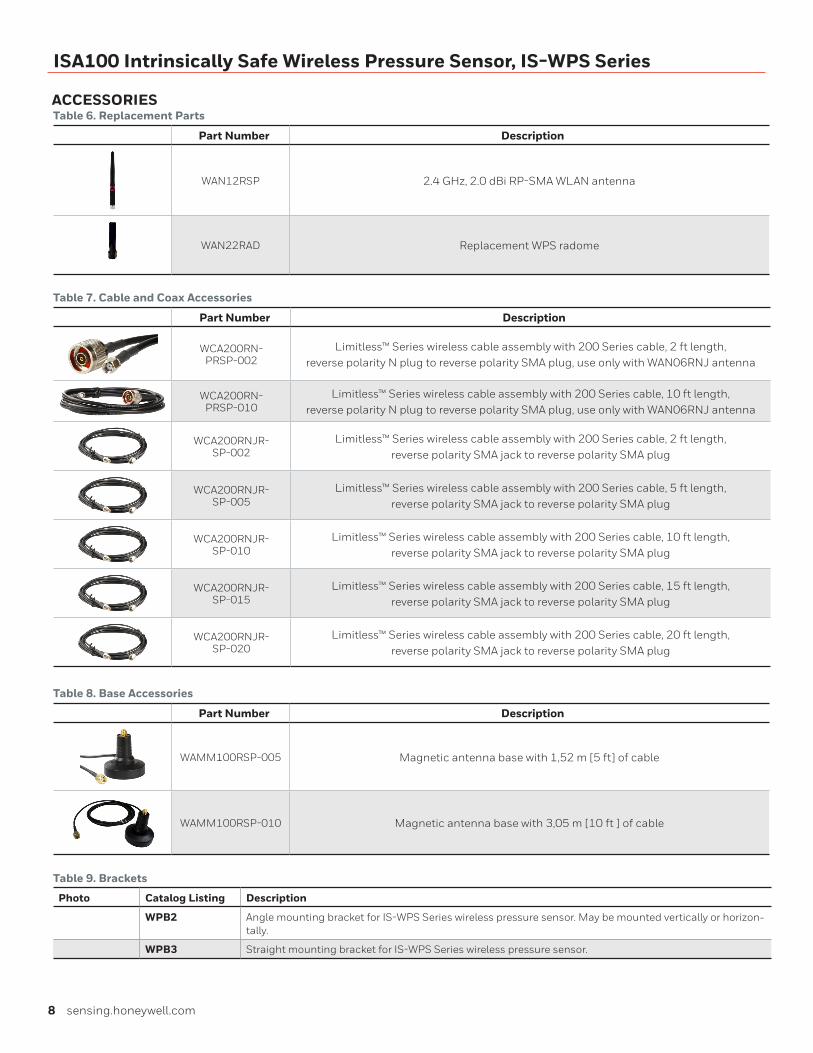
ACCESSORIESTable 6. Replacement Parts
Part Number Description
WAN12RSP 2.4 GHz, 2.0 dBi RP-SMA WLAN antenna
WAN22RAD Replacement WPS radome
Table 7. Cable and Coax Accessories
Part Number Description
WCA200RN-PRSP-002
Limitless™ Series wireless cable assembly with 200 Series cable, 2 ft length, reverse polarity N plug to reverse polarity SMA plug, use only with WAN06RNJ antenna
WCA200RN-PRSP-010
Limitless™ Series wireless cable assembly with 200 Series cable, 10 ft length, reverse polarity N plug to reverse polarity SMA plug, use only with WAN06RNJ antenna
WCA200RNJR-SP-002
Limitless™ Series wireless cable assembly with 200 Series cable, 2 ft length, reverse polarity SMA jack to reverse polarity SMA plug
WCA200RNJR-SP-005
Limitless™ Series wireless cable assembly with 200 Series cable, 5 ft length, reverse polarity SMA jack to reverse polarity SMA plug
WCA200RNJR-SP-010
Limitless™ Series wireless cable assembly with 200 Series cable, 10 ft length, reverse polarity SMA jack to reverse polarity SMA plug
WCA200RNJR-SP-015
Limitless™ Series wireless cable assembly with 200 Series cable, 15 ft length, reverse polarity SMA jack to reverse polarity SMA plug
WCA200RNJR-SP-020
Limitless™ Series wireless cable assembly with 200 Series cable, 20 ft length, reverse polarity SMA jack to reverse polarity SMA plug
Table 8. Base Accessories
Part Number Description
WAMM100RSP-005 Magnetic antenna base with 1,52 m [5 ft] of cable
WAMM100RSP-010 Magnetic antenna base with 3,05 m [10 ft ] of cable
Table 9. Brackets
Photo Catalog Listing Description
WPB2 Angle mounting bracket for IS-WPS Series wireless pressure sensor. May be mounted vertically or horizon-tally.
WPB3 Straight mounting bracket for IS-WPS Series wireless pressure sensor.
Safety and Productivity Solutions 9
ISA100 Intrinsically Safe Wireless Pressure Sensor, IS-WPS Series
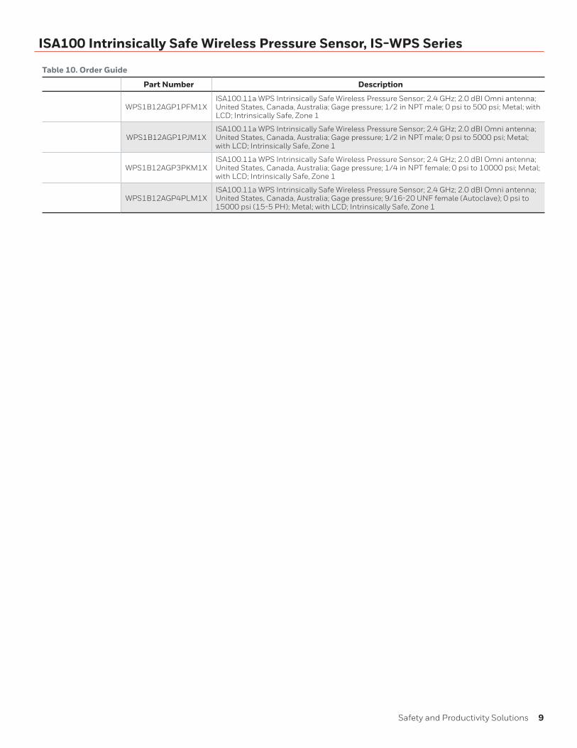
Table 10. Order Guide
Part Number Description
WPS1B12AGP1PFM1XISA100.11a WPS Intrinsically Safe Wireless Pressure Sensor; 2.4 GHz; 2.0 dBI Omni antenna; United States, Canada, Australia; Gage pressure; 1/2 in NPT male; 0 psi to 500 psi; Metal; with LCD; Intrinsically Safe, Zone 1
WPS1B12AGP1PJM1XISA100.11a WPS Intrinsically Safe Wireless Pressure Sensor; 2.4 GHz; 2.0 dBI Omni antenna; United States, Canada, Australia; Gage pressure; 1/2 in NPT male; 0 psi to 5000 psi; Metal; with LCD; Intrinsically Safe, Zone 1
WPS1B12AGP3PKM1XISA100.11a WPS Intrinsically Safe Wireless Pressure Sensor; 2.4 GHz; 2.0 dBI Omni antenna; United States, Canada, Australia; Gage pressure; 1/4 in NPT female; 0 psi to 10000 psi; Metal; with LCD; Intrinsically Safe, Zone 1
WPS1B12AGP4PLM1XISA100.11a WPS Intrinsically Safe Wireless Pressure Sensor; 2.4 GHz; 2.0 dBI Omni antenna; United States, Canada, Australia; Gage pressure; 9/16-20 UNF female (Autoclave); 0 psi to 15000 psi (15-5 PH); Metal; with LCD; Intrinsically Safe, Zone 1
10 sensing.honeywell.com
ISA100 Intrinsically Safe Wireless Pressure Sensor, IS-WPS Series
PRESSURE SENSOR GLOSSARY OF TERMS
Absolute Pressure (a) – Pressure measured relative to a per-fect vacuum (zero pressure) reference.
Absolute Pressure Sensor – Product whose output is propor-tional to the difference between applied pressure and a built-in fixed reference to vacuum (zero pressure). Typically the Mini-mum Operating Pressure (Pmin.) is set to absolute zero pres-sure (perfect vacuum).
Accuracy – The maximum deviation in output from a Best Fit Straight Line (BFSL) fitted to output measured over the Com-pensated Pressure Range at Reference Temperature. Includes all errors due to: Pressure Non-Linearity, Pressure Hysteresis and Non-Repeatability.
Best Fit Straight Line (BFSL) – The straight line fitted through a set of points which minimizes the sum of the square of the deviations of each of the points from the straight line (‘least-squares’ method). See also Pressure Non-Linearity.
Burst Pressure – The maximum pressure that may be applied to any port of the product without causing escape of pressure media. The product should not be expected to function after exposure to any pressure beyond the burst pressure. See also Overpressure.
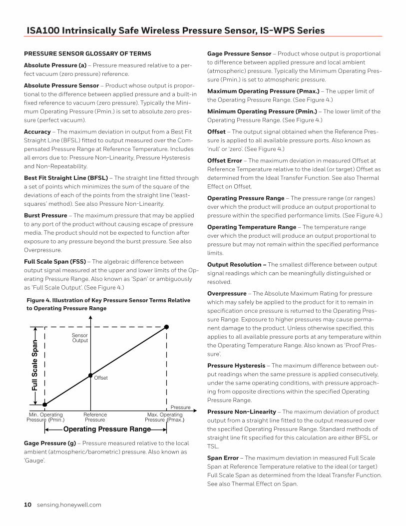
Full Scale Span (FSS) – The algebraic difference between output signal measured at the upper and lower limits of the Op-erating Pressure Range. Also known as ‘Span’ or ambiguously as ‘Full Scale Output’. (See Figure 4.)
Figure 4. Illustration of Key Pressure Sensor Terms Relative to Operating Pressure Range
Full
Sca
le S
pan
Operating Pressure Range
Max. Operating Pressure (Pmax.)
Min. Operating Pressure (Pmin.)
Reference Pressure
Pressure
Sensor Output
Offset
Gage Pressure (g) – Pressure measured relative to the local ambient (atmospheric/barometric) pressure. Also known as ‘Gauge’.
Gage Pressure Sensor – Product whose output is proportional to difference between applied pressure and local ambient (atmospheric) pressure. Typically the Minimum Operating Pres-sure (Pmin.) is set to atmospheric pressure.
Maximum Operating Pressure (Pmax.) – The upper limit of the Operating Pressure Range. (See Figure 4.)
Minimum Operating Pressure (Pmin.) – The lower limit of the Operating Pressure Range. (See Figure 4.)
Offset – The output signal obtained when the Reference Pres-sure is applied to all available pressure ports. Also known as ‘null’ or ‘zero’. (See Figure 4.)
Offset Error – The maximum deviation in measured Offset at Reference Temperature relative to the ideal (or target) Offset as determined from the Ideal Transfer Function. See also Thermal Effect on Offset.
Operating Pressure Range – The pressure range (or ranges) over which the product will produce an output proportional to pressure within the specified performance limits. (See Figure 4.)
Operating Temperature Range – The temperature range over which the product will produce an output proportional to pressure but may not remain within the specified performance limits.
Output Resolution – The smallest difference between output signal readings which can be meaningfully distinguished or resolved.
Overpressure – The Absolute Maximum Rating for pressure which may safely be applied to the product for it to remain in specification once pressure is returned to the Operating Pres-sure Range. Exposure to higher pressures may cause perma-nent damage to the product. Unless otherwise specified, this applies to all available pressure ports at any temperature within the Operating Temperature Range. Also known as ‘Proof Pres-sure’.
Pressure Hysteresis – The maximum difference between out-put readings when the same pressure is applied consecutively, under the same operating conditions, with pressure approach-ing from opposite directions within the specified Operating Pressure Range.
Pressure Non-Linearity – The maximum deviation of product output from a straight line fitted to the output measured over the specified Operating Pressure Range. Standard methods of straight line fit specified for this calculation are either BFSL or TSL.
Span Error – The maximum deviation in measured Full Scale Span at Reference Temperature relative to the ideal (or target) Full Scale Span as determined from the Ideal Transfer Function. See also Thermal Effect on Span.
Safety and Productivity Solutions 11
ISA100 Intrinsically Safe Wireless Pressure Sensor, IS-WPS Series
Thermal Effect on Offset – The maximum deviation in Offset due to changes in temperature over the Compensated Temper-ature Range, relative to Offset measured at Reference Tempera-ture.
Thermal Effect on Span – The maximum deviation in Full Scale Span due to changes in temperature over the Compen-sated Temperature Range, relative to Full Scale Span measured at Reference Temperature.
Thermal Hysteresis – The maximum difference between out-put readings when the same temperature is reached consecu-tively, under the same operating conditions, with temperature approaching from opposite directions within the specified temperature range.
All Possible Errors
+
+
+
+
+
Pressure Non-Linearity
Pressure Hysteresis
Pressure Non-Repeatability
Thermal Effect on Zero
Thermal Effect on Span
Thermal Hysteresis
TotalError Band
Accuracy=
=
+
+
Offset
Full Scale Span
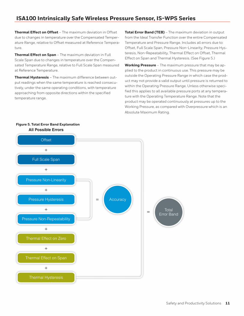
Figure 5. Total Error Band Explanation
Total Error Band (TEB) – The maximum deviation in output from the Ideal Transfer Function over the entire Compensated Temperature and Pressure Range. Includes all errors due to: Offset, Full Scale Span, Pressure Non-Linearity, Pressure Hys-teresis, Non-Repeatability, Thermal Effect on Offset, Thermal Effect on Span and Thermal Hysteresis. (See Figure 5.)
Working Pressure – The maximum pressure that may be ap-plied to the product in continuous use. This pressure may be outside the Operating Pressure Range in which case the prod-uct may not provide a valid output until pressure is returned to within the Operating Pressure Range. Unless otherwise speci-fied this applies to all available pressure ports at any tempera-ture with the Operating Temperature Range. Note that the product may be operated continuously at pressures up to the Working Pressure, as compared with Overpressure which is an
Absolute Maximum Rating.
12 sensing.honeywell.com
ISA100 Intrinsically Safe Wireless Pressure Sensor, IS-WPS Series
Third Party Software LicenseThis product contains software provided by third parties, which may include the below listed components. The Honeywell product that includes this file does not necessarily use all of the third party software components referred to below.
Package(s) using BSD 3-clause (Texas Instruments) license* Texas Instruments 802.15.4 MAC [Copyright © 2010 Texas Instruments Incorporated - http://www.ti.com/]
License Text [BSD 3-clause (Texas Instruments)]------------------------------------------------Copyright © 2010 Texas Instruments Incorporated - http://www.ti.com/
Redistribution and use in source and binary forms, with or without modification, are permitted provided that the following conditionsare met:
1) Redistributions of source code must retain the above copyright notice, this list of conditions and the follow-ing disclaimer.
2) Redistributions in binary form must reproduce the above copyright notice, this list of conditions and the following disclaimer in the documentation and/or other materials provided with the distribution.
3) Neither the name of Texas Instruments Incorporated nor the names of its contributors may be used to en-dorse or promote products derived from this software without specific prior written permission.
THIS SOFTWARE IS PROVIDED BY THE COPYRIGHT HOLD-ERS AND CONTRIBUTORS “AS IS” AND ANY EXPRESS OR IMPLIED WARRANTIES, INCLUDING, BUT NOT LIMITED TO, THE IMPLIED WARRANTIES OF MERCHANTABILITY AND FIT-NESS FOR A PARTICULAR PURPOSE ARE DISCLAIMED. IN NO EVENT SHALL THE COPYRIGHT OWNER OR CONTRIBUTORS BE LIABLE FOR ANY DIRECT, INDIRECT, INCIDENTAL, SPE-CIAL, EXEMPLARY, OR CONSEQUENTIAL DAMAGES (INCLUD-ING, BUT NOT LIMITED TO, PROCUREMENT OF SUBSTITUTE GOODS OR SERVICES; LOSS OF USE, DATA, OR PROFITS; OR BUSINESS INTERRUPTION) HOWEVER CAUSED AND ON ANY THEORY OF LIABILITY, WHETHER IN CONTRACT, STRICT LIA-BILITY, OR TORT (INCLUDING NEGLIGENCE OR OTHERWISE) ARISING IN ANY WAY OUT OF THE USE OF THIS SOFTWARE, EVEN IF ADVISED OF THE POSSIBILITY OF SUCH DAMAGE.
Package(s) using Analog Devices License* AD7799 Communication Driver [Copyright 2012 ©Analog Devices, Inc.]
License Text (Analog Devices, Inc. License)--------------------------------------------Copyright 2012 ©Analog Devices, Inc. All rights reserved. Redistribution and use in source and binary forms, with or without modification, are permitted provided that the following conditions are met:
- Redistributions of source code must retain the above copyright notice, this list of conditions and the follow-ing disclaimer.
- Redistributions in binary form must reproduce the above copyright notice, this list of conditions and the following disclaimer in the documentation and/or other materials provided with the distribution.
- Neither the name of Analog Devices, Inc. nor the names of its contributors may be used to endorse or promote products derived from this software without specific prior written permission.
- The use of this software may or may not infringe the patent rights of one or more patent holders. This license does not release you from the requirement that you obtain separate licenses from these patent holders to use this software.
- Use of the software either in source or binary form must be run on or directly connected to an Analog Devices Inc. component.
THIS SOFTWARE IS PROVIDED BY ANALOG DEVICES “AS IS” AND ANY EXPRESS OR IMPLIED WARRANTIES, INCLUDING, BUT NOT LIMITED TO, NON-INFRINGEMENT, MERCHANT-ABILITY AND FITNESS FOR A PARTICULAR PURPOSE ARE DISCLAIMED. IN NO EVENT SHALL ANALOG DEVICES BE LIABLE FOR ANY DIRECT, INDIRECT, INCIDENTAL, SPECIAL, EXEMPLARY, OR CONSEQUENTIAL DAMAGES (INCLUDING, BUT NOT LIMITED TO, INTELLECTUAL PROPERTY RIGHTS, PROCUREMENT OF SUBSTITUTE GOODS OR SERVICES; LOSS OF USE, DATA, OR PROFITS; OR BUSINESS INTERRUPTION) HOWEVER CAUSED AND ON ANY THEORY OF LIABILITY, WHETHER IN CONTRACT, STRICT LIABILITY, OR TORT (IN-CLUDING NEGLIGENCE OR OTHERWISE) ARISING IN ANY WAY OUT OF THE USE OF THIS SOFTWARE, EVEN IF ADVISED OF THE POSSIBILITY OF SUCH DAMAGE.
Warranty/RemedyHoneywell warrants goods of its manufacture as being free of defective materials and faulty workmanship. Honeywell’s standard product warranty applies unless agreed to otherwise by Honeywell in writing; please refer to your order acknowl-edgement or consult your local sales office for specific war-ranty details. If warranted goods are returned to Honeywell during the period of coverage, Honeywell will repair or replace, at its option, without charge those items that Honeywell, in its sole discretion, finds defective. The foregoing is buyer’s sole remedy and is in lieu of all other warranties, expressed or implied, including those of merchantability and fitness for a particular purpose. In no event shall Honeywell be liable for consequential, special, or indirect damages.
While Honeywell may provide application assistance person-ally, through our literature and the Honeywell web site, it is customer’s sole responsibility to determine the suitability of the product in the application.
Specifications may change without notice. The information we supply is believed to be accurate and reliable as of this printing. However, Honeywell assumes no responsibility for its use.
32317842-1-EN IL50 GLO August 2016© 2016 Honeywell International Inc. All rights reserved.Hastelloy® is the registered trademark name of Haynes International, Inc
m WARNINGPERSONAL INJURYDO NOT USE these products as safety or emergency stop devices or in any other application where failure of the product could result in personal injury.
Failure to comply with these instructions could result in death or serious injury.
m WARNINGMISUSE OF DOCUMENTATION• The information presented in this product sheet is for
reference only. Do not use this document as a product installation guide.
• Complete installation, operation, and maintenance information is provided in the instructions supplied with each product.
Failure to comply with these instructions could result in death or serious injury.
Find out moreHoneywell serves its customers
through a worldwide network
of sales offices, representatives
and distributors. For applica-
tion assistance, current specifi-
cations, pricing or name of the
nearest Authorized Distributor,
contact your local sales office.
To learn more about Honey-
well’s sensing and control
products,
call +1-815-235-6847 or 1-800-537-6945, visit sensing.honeywell.com, or e-mail inquiries to
ADDITIONAL MATERIALSThe following associated literature is available on the Honeywell web site at sensing.honeywell.com:
• Installation and technical manual
• Installation instructions
• Limitless™ product range guide
• Application note
Honeywell Safety and Productivity Solutions9680 Old Bailes Road
Fort Mill, SC 29707
honeywell.com