is/iso 5366-1 (2000): anaesthetic and respiratory equipment
TRANSCRIPT

Disclosure to Promote the Right To Information
Whereas the Parliament of India has set out to provide a practical regime of right to information for citizens to secure access to information under the control of public authorities, in order to promote transparency and accountability in the working of every public authority, and whereas the attached publication of the Bureau of Indian Standards is of particular interest to the public, particularly disadvantaged communities and those engaged in the pursuit of education and knowledge, the attached public safety standard is made available to promote the timely dissemination of this information in an accurate manner to the public.
इंटरनेट मानक
“!ान $ एक न' भारत का +नम-ण”Satyanarayan Gangaram Pitroda
“Invent a New India Using Knowledge”
“प0रा1 को छोड न' 5 तरफ”Jawaharlal Nehru
“Step Out From the Old to the New”
“जान1 का अ+धकार, जी1 का अ+धकार”Mazdoor Kisan Shakti Sangathan
“The Right to Information, The Right to Live”
“!ान एक ऐसा खजाना > जो कभी च0राया नहB जा सकता है”Bhartṛhari—Nītiśatakam
“Knowledge is such a treasure which cannot be stolen”
“Invent a New India Using Knowledge”
है”ह”ह
IS/ISO 5366-1 (2000): Anaesthetic and Respiratory Equipment- Tracheostomy Tubes, Part 1: Tubes and Connectors for usein Adults [MHD 11: Anaesthetic, Resuscitation and AlliedEquipment]


IS/ISO 5366-1 : 2000[Superseding IS 12505 (Parts 1 and 2) : 1988]
© BIS 2012
February 2012 Price Group 6
B U R E A U O F I N D I A N S T A N D A R D SMANAK BHAVAN, 9 BAHADUR SHAH ZAFAR MARG
NEW DELHI 110002
Hkkjrh; ekud
,uLFkhfl;k ,oa 'olu midj.k —
VªsdhvksLVkWeh gsrq ufy;k¡Hkkx 1 o;Ldksa osQ fy, ç;ksx esa vkus okyh ufy;k¡ ,oa la;kstd
Indian Standard
ANAESTHETIC AND RESPIRATORY EQUIPMENT —TRACHEOSTOMY TUBES
PART 1 TUBES AND CONNECTORS FOR USE IN ADULTS
ICS 11.040.10

Anaesthetic, Resuscitation and Allied Equipment Sectional Committee, MHD 11
NATIONAL FOREWORD
This Indian Standard (Part 1) which is identical with ISO 5366-1 : 2000 ‘Anaesthetic and respiratoryequipment — Tracheostomy tubes — Part 1: Tubes and connectors for use in adults’ issued by theInternational Organization for Standardization (ISO) was adopted by the Bureau of Indian Standardson the recommendation of the Anaesthetic, Resuscitation and Allied Equipment Sectional Committeeand approval of the Medical Equipment and Hospital Planning Division Council.
This standard was earlier published as IS 12505 (Part 1) : 1988 ‘Tracheostomy tubes: Part 1 Connectors’and IS 12505 (Part 2) : 1988 ‘Tracheostomy tubes: Part 2 Basic requirements’ based on ISO 5366-1 :1986 and ISO 5366-2 : 1985 respectively. Both these ISO Standards have been replaced byISO 5366-1 : 2000. This standard is now being published in a single number as IS/ISO based onISO 5366-1 : 2000 to align with the latest international practices. This standard will supersedeIS 12505 (Parts 1 and 2) : 1988 and after the publication of this standard IS 12505 (Parts 1 and 2)shall be treated as withdrawn.
This standard is one of a series dealing with anaesthetic equipment, and is concerned with the basicrequirements and method of size designation of tracheostomy tubes made of plastics materialsand/or rubber. Specialized tubes, for example, those without a connector at the machine end intendedfor spontaneously breathing patients, and those with reinforced walls or tubes made of metal areexcluded from the scope of this standard.
This standard specifies requirements for tracheostomy tubes with an inside diameter of 6.5 mm orgreater. ISO 5366-3 specifies requirements for tracheostomy tubes with an inside diameter from2.5 to 6.0 mm for paediatric use.
The method of describing tube dimensions and configuration has been devised in order to assist theclinician in the selection of a suitable tube to conform as far as possible to a particular patient’sanatomy. Size is designated by inside diameter, which is important because of its relation to resistanceto gas flow. Because the stomal and tracheal diameter are important when selecting tubes, it isconsidered essential that the outside diameter be stated for each size of tube.
Cuffed tracheostomy tubes can be characterized by a combination of the tube inside and outsidediameters and by the cuff resting diameter.
The relationship of cuff and tracheal diameters dictates the intra-cuff pressures required to provide aseal. Excessive pressure on the tracheal wall can obstruct capillary blood flow.
A range of cuff designs is available to meet the particular clinical requirements. This standard requiresthat the resting diameter of the cuff is marked on the unit package, as this information allows theclinician to match the product to the application.
A 15 mm male conical connector in accordance with IS/ISO 5356-1 : 2004 should be used fortracheostomy tubes, as for tracheal tubes, to ensure compatibility with the breathing system of ananaesthetic machine or ventilator.
The tracheostomy tube connector should be permanently attached to the tracheostomy tube to preventinadvertent disconnection of the connector from the tube.
Flammability of tracheostomy tubes, for example, if flammable anaesthetics, electrosurgical units,or lasers are used in oxidant-enriched atmospheres, is a well-recognized hazard, that is, addressedby appropriate clinical management, and is outside the scope of this standard.
(Continued on third cover)

1 Scope
This part of ISO 5366 specifies requirements for tracheostomy tubes made of plastics materials and/or rubber havinginside diameters of or greater. Such tubes are primarily designed for patients who require anaesthesia, arti-ficial ventilation or other respiratory support, but need not be restricted to these uses.
This part of ISO 5366 is not applicable to specialized tubes, and does not address flammability of tracheostomytubes.
2 Normative references
The following normative documents contain provisions which, through reference in this text, constitute provisions ofthis part of ISO 5366. For dated references, subsequent amendments to, or revisions of, any of these publications donot apply. However, parties to agreements based on this part of ISO 5366 are encouraged to investigate the possi-bility of applying the most recent editions of the normative documents indicated below. For undated references, thelatest edition of the normative document referred to applies. Members of ISO and IEC maintain registers of currentlyvalid International Standards.
ISO 594-1, Conical fittings with a 6 % (Luer) taper for syringes, needles and certain other medical equipment —Part 1: General requirements.
ISO 4135, Anaesthetic and respiratory equipment — Vocabulary.
ISO 5356-1, Anaesthetic and respiratory equipment — Conical connectors — Part 1: Cones and sockets.
ISO 5361, Anaesthetic and respiratory equipment — Tracheal tubes and connectors.
ISO 10993-1, Biological evaluation of medical devices — Part 1: Evaluation and testing.
ISO 11607, Packaging for terminally sterilized medical devices.
EN 556 :1994, Sterilization of medical devices — Requirements for medical devices to be labelled “STERILE”.
3 Terms and definitions
For the purposes of this part of ISO 5366, the terms and definitions given in ISO 4135 and the following apply.
3.1tracheostomy tubetube designed for insertion into the trachea through a tracheostomy
NOTE See Figure 1 a) and b) for an illustration of a typical tracheostomy tube and the associated nomenclature.
6,5 mm
Indian StandardANAESTHETIC AND RESPIRATORY EQUIPMENT —
TRACHEOSTOMY TUBESPART 1 TUBES AND CONNECTORS FOR USE IN ADULTS
IS/ISO 5366-1 : 2000
1

a) View 1
Key1 Inflating tube2 Neck-plate3 Cuff, if present4 Patient end5 Alternative integral
pilot balloon/valveassembly
6 male conicalfitting in accordancewith ISO 5356-1
7 Machine end8 Outer tube9 Pilot balloon10 Inflation valve or
closure device11 Tip rounded12 Bevel, if present
b) View 2
Figure 1 — Typical tracheostomy tube
15 mm
IS/ISO 5366-1 : 2000
2

3.2machine end�of a tracheostomy tube� that end which is intended to project from the neck of a patient
3.3machine end�of a connector or an adaptor� that end intended to mate with the breathing system of an anaesthetic machine or ven-tilator
3.4patient endthat end of a tracheostomy tube which is intended to be inserted into the trachea
3.5nominal lengthdistance from the patient side of the neck-plate to the patient end along the centreline
See Figure 2.
NOTE When the neck-plate is movable, the nominal length is variable.
Key1 Centreline
2 Neck-plate3 Datum plane
NOTE The angle is the obtuse angle formed between the long axes of the tube at the machine and patient ends.
Figure 2 — Basic dimensions of tracheostomy tubes
θ
IS/ISO 5366-1 : 2000
3

3.6
outer tube
that part of the tracheostomy tube which is normally in contact with the tissues
3.7
inner tube
tube which fits closely to the inside contours of the outer tube (i.e. a tracheostomy tube)
3.8
cuff
inflatable balloon permanently attached around the tracheostomy tube near the patient end to provide a seal be-tween the tube and the trachea
3.9
inflating tube
tube through which a cuff is inflated
3.10
pilot balloon
balloon fitted to an inflating tube to indicate inflation of a cuff
3.11
neck-plate
shield
that part of a tracheostomy tube which approximates to the contour of a patient's neck and is used to secure the tubein position
3.12
introducer
obturator
specially adapted stylet to facilitate the introduction of the outer tube into the trachea
3.13
bevel
slanted portion at the patient end of a tracheostomy tube
3.14
angle of bevel
acute angle between the plane of the bevel and the longitudinal axis of a tracheostomy tube at the patient end
4 Size designation and dimensions
4.1 Inside diameter
4.1.1 The size of the tracheostomy tube (outer tube) shall be designated by the nominal inside diameter (ID) of thetube, expressed in millimetres, as measured at the minimum inside diameter, in accordance with Table 1, excludingany encroachment allowed by 6.5.1.
IS/ISO 5366-1 : 2000
4

4.1.2 For tracheostomy tubes with the conical connector permanently attached to the inner tube, the size shall bedesignated by the nominal inside diameter (ID) of the inner tube, expressed in millimetres, in accordance withTable 1.
4.2 Outside diameter
4.2.1 The outside diameter (OD) of sections and (see Figure 2) of the tube, other than at the cuff, if provided,shall be expressed in millimetres to the nearest .
NOTE The stated outside diameter relates to that portion of the tube intended to be within the wall and the lumen of the trachea.
4.2.2 The actual outside diameter of section (see Figure 2) other than at the cuff, if provided, shall be the markedoutside diameter subject to a tolerance of .
4.2.3 The actual outside diameter of section shall be the marked outside diameter subject to a tolerance of.
4.3 Length
4.3.1 The nominal length (dimensions + + in Figure 2) shall be measured from the patient side of the neck-plate to the patient end including the bevel, if present, and expressed in millimetres.
4.3.2 The actual nominal length (dimensions + + in Figure 2) shall be the marked nominal length subject to atolerance of .
4.3.3 For tubes with an adjustable neck-plate, the range of measurements for nominal length (see Figure 2) shall beexpressed in millimetres.
4.3.4 Dimensions , and shall be expressed in millimetres (see Figure 2).
NOTE Dimensions and/or can be, or approach, zero.
4.4 Angle
The angle (see Figure 2) shall be expressed in degrees.
Table 1 — Size designation of tracheostomy tubes — Dimensions and tolerances
Dimensions in millimetres
Designated size Inside diameter and tolerance
6,5
7,0
7,5
8,0
8,5
9,0
9,5
10,0
10,5
11,0
6,5� 0,2
7,0� 0,2
7,5� 0,2
8,0� 0,2
8,5� 0,2
9,0� 0,2
9,5� 0,2
10,0� 0,2
10,5� 0,2
11,0� 0,2
a c0,1 mm
a� 0,2 mm
c� 0,5 mm
a b c
a b c� 2 mm
a b c
a b
θ
θ
IS/ISO 5366-1 : 2000
5
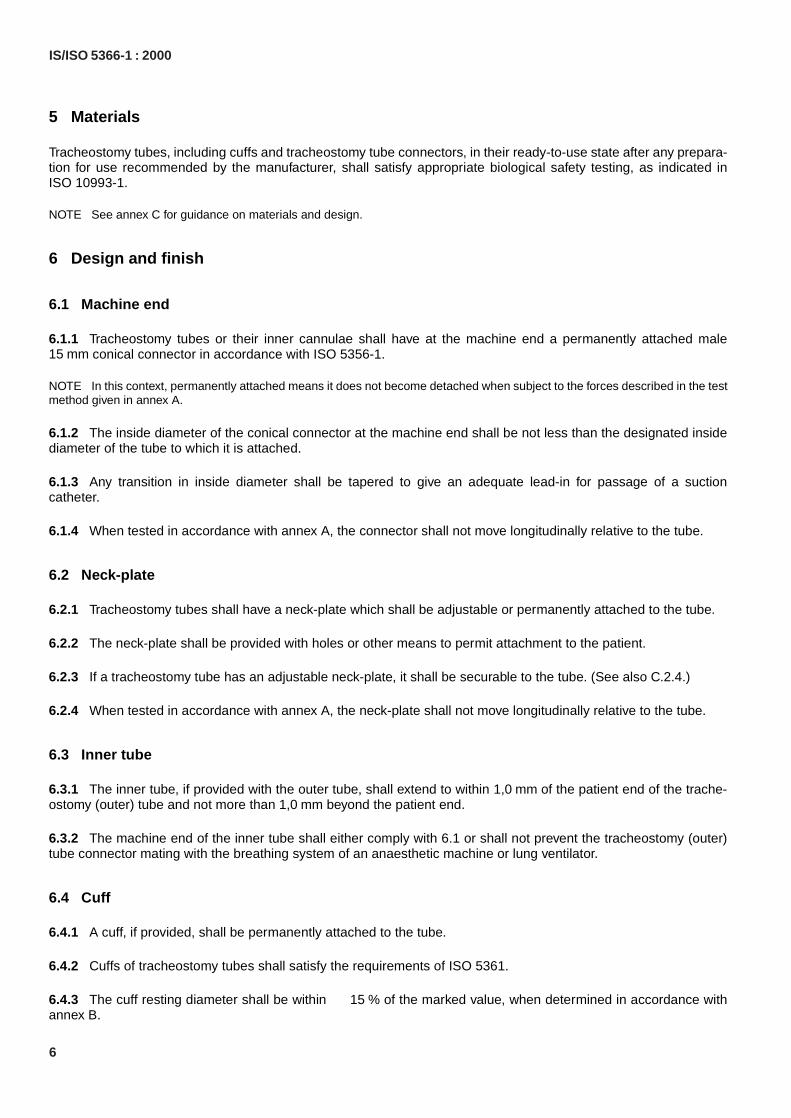
5 Materials
Tracheostomy tubes, including cuffs and tracheostomy tube connectors, in their ready-to-use state after any prepara-tion for use recommended by the manufacturer, shall satisfy appropriate biological safety testing, as indicated inISO 10993-1.
NOTE See annex C for guidance on materials and design.
6 Design and finish
6.1 Machine end
6.1.1 Tracheostomy tubes or their inner cannulae shall have at the machine end a permanently attached maleconical connector in accordance with ISO 5356-1.
NOTE In this context, permanently attached means it does not become detached when subject to the forces described in the testmethod given in annex A.
6.1.2 The inside diameter of the conical connector at the machine end shall be not less than the designated insidediameter of the tube to which it is attached.
6.1.3 Any transition in inside diameter shall be tapered to give an adequate lead-in for passage of a suctioncatheter.
6.1.4 When tested in accordance with annex A, the connector shall not move longitudinally relative to the tube.
6.2 Neck-plate
6.2.1 Tracheostomy tubes shall have a neck-plate which shall be adjustable or permanently attached to the tube.
6.2.2 The neck-plate shall be provided with holes or other means to permit attachment to the patient.
6.2.3 If a tracheostomy tube has an adjustable neck-plate, it shall be securable to the tube. (See also C.2.4.)
6.2.4 When tested in accordance with annex A, the neck-plate shall not move longitudinally relative to the tube.
6.3 Inner tube
6.3.1 The inner tube, if provided with the outer tube, shall extend to within of the patient end of the trache-ostomy (outer) tube and not more than beyond the patient end.
6.3.2 The machine end of the inner tube shall either comply with 6.1 or shall not prevent the tracheostomy (outer)tube connector mating with the breathing system of an anaesthetic machine or lung ventilator.
6.4 Cuff
6.4.1 A cuff, if provided, shall be permanently attached to the tube.
6.4.2 Cuffs of tracheostomy tubes shall satisfy the requirements of ISO 5361.
6.4.3 The cuff resting diameter shall be within of the marked value, when determined in accordance withannex B.
15 mm
1,0 mm1,0 mm
� 15 %
IS/ISO 5366-1 : 2000
6

6.5 Inflating tubes for cuffs
6.5.1 Inflating tube
The inflating tube shall have an outside diameter of not more than . The wall around the inflation lumen shallnot encroach on the lumen of the tracheostomy tube by more than of the inside diameter of the tracheostomytube.
The wall around the inflation lumen should not project substantially on the outside surface of the tracheostomy tube.
6.5.2 Pilot balloon
6.5.2.1 The inflating tube shall have a pilot balloon and/or other means to indicate inflation/deflation of the cuff.
NOTE This (these) device(s) can also serve as a pressure-indicating or -limiting device.
6.5.2.2 The intentional evacuation of the cuff shall not be prevented by the inflating tube, inflating valve or any clo-sure device.
6.5.3 Free end of inflating tubes for cuffs
The end of the inflating tube shall be either open or sealed with a closure device or inflation valve, but in all instancesit shall be capable of accepting a male conical fitting with a taper (Luer) complying with ISO 594-1. The length[see Figure 1 a), dimension ] of the free end of inflating tubes shall be not less than unless an inflation valveor closure device is provided.
If an inflation valve or closure device is provided, the length [see Figure 1 b), dimension ] between the pilot balloon(or other device) and the female fitting which accepts a male Luer conical fitting shall be not less than unlessthe pilot balloon and valve or closure device are integral.
NOTE This is to facilitate clamping of the inflating tube.
6.6 Patient end
If a bevel is present, the angle of bevel ( ) shall be not less than (see Figure 1 inset).
6.7 Introducer
If provided, the introducer, when correctly seated, shall not fall out of the tracheostomy tube under its own weightwhen the tube is held by the neck-plate with the patient end uppermost.
The introducer should be freely removable in use.
7 Requirements for tracheostomy tubes supplied sterile
7.1 Sterility assurance
Tracheostomy tubes supplied and marked as “STERILE” shall satisfy the requirements of 4.1 of EN 556:1994.
2,5 mm10 %
6 %l1 40 mm
l210 mm
β 50◦
IS/ISO 5366-1 : 2000
7
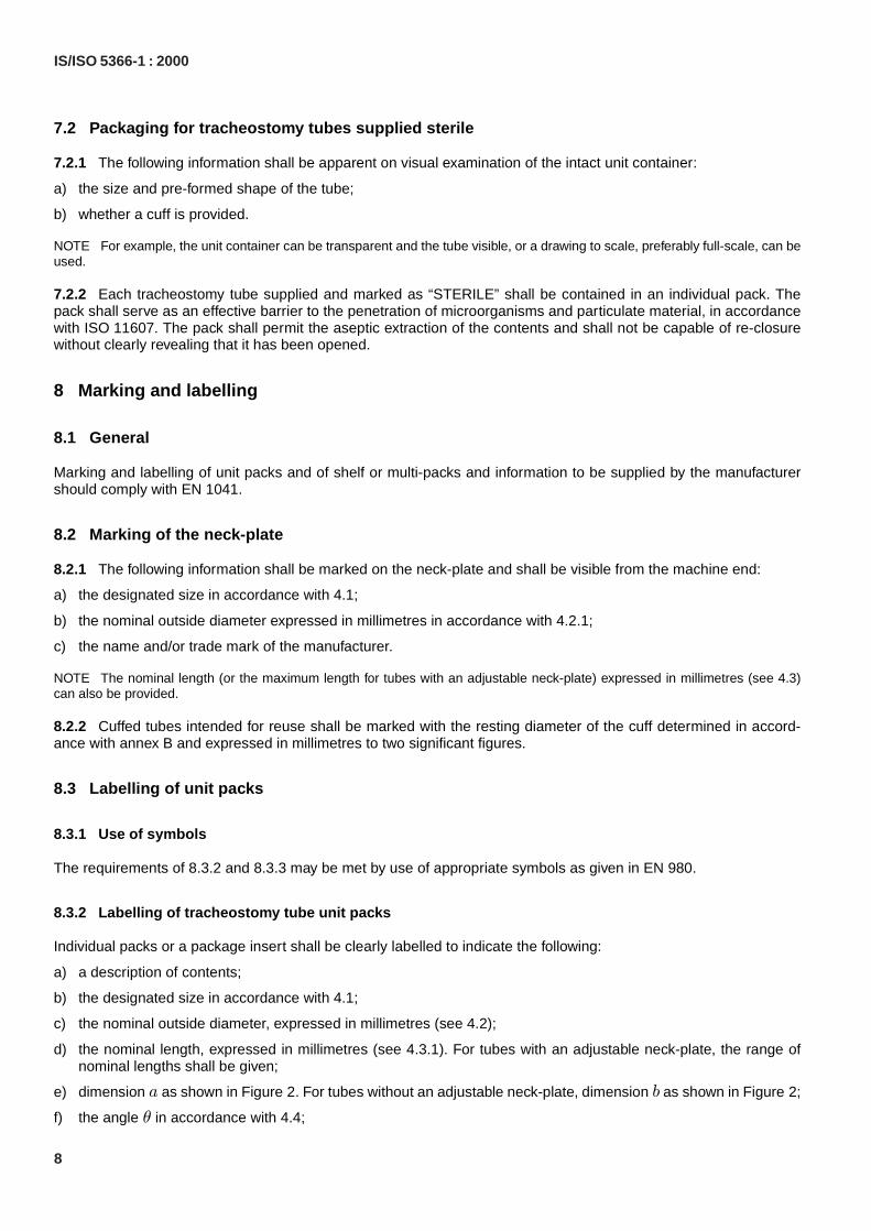
7.2 Packaging for tracheostomy tubes supplied sterile
7.2.1 The following information shall be apparent on visual examination of the intact unit container:
a) the size and pre-formed shape of the tube;
b) whether a cuff is provided.
NOTE For example, the unit container can be transparent and the tube visible, or a drawing to scale, preferably full-scale, can beused.
7.2.2 Each tracheostomy tube supplied and marked as “STERILE” shall be contained in an individual pack. Thepack shall serve as an effective barrier to the penetration of microorganisms and particulate material, in accordancewith ISO 11607. The pack shall permit the aseptic extraction of the contents and shall not be capable of re-closurewithout clearly revealing that it has been opened.
8 Marking and labelling
8.1 General
Marking and labelling of unit packs and of shelf or multi-packs and information to be supplied by the manufacturershould comply with EN 1041.
8.2 Marking of the neck-plate
8.2.1 The following information shall be marked on the neck-plate and shall be visible from the machine end:
a) the designated size in accordance with 4.1;
b) the nominal outside diameter expressed in millimetres in accordance with 4.2.1;
c) the name and/or trade mark of the manufacturer.
NOTE The nominal length (or the maximum length for tubes with an adjustable neck-plate) expressed in millimetres (see 4.3)can also be provided.
8.2.2 Cuffed tubes intended for reuse shall be marked with the resting diameter of the cuff determined in accord-ance with annex B and expressed in millimetres to two significant figures.
8.3 Labelling of unit packs
8.3.1 Use of symbols
The requirements of 8.3.2 and 8.3.3 may be met by use of appropriate symbols as given in EN 980.
8.3.2 Labelling of tracheostomy tube unit packs
Individual packs or a package insert shall be clearly labelled to indicate the following:
a) a description of contents;
b) the designated size in accordance with 4.1;
c) the nominal outside diameter, expressed in millimetres (see 4.2);
d) the nominal length, expressed in millimetres (see 4.3.1). For tubes with an adjustable neck-plate, the range ofnominal lengths shall be given;
e) dimension as shown in Figure 2. For tubes without an adjustable neck-plate, dimension as shown in Figure 2;
f) the angle in accordance with 4.4;
a b
θ
IS/ISO 5366-1 : 2000
8

g) the name and/or trade mark of the manufacturer and/or supplier;
h) the batch number;
i) unless the tracheostomy tube is intended and marked as being for single use, instructions for cleaning and disin-fection or sterilization;
j) the word “STERILE” or “NON-STERILE” as appropriate;
k) for tubes not intended for re-use, the words “single-use” or equivalent;
l) for cuffed tubes, the resting diameter of the cuff, determined in accordance with annex B and expressed in milli-metres to two significant figures;
m) if an inner tube is provided in the unit pack, the nominal inside diameter of the inner tube.
It is strongly recommended that the 'use by' date also be given.
8.3.3 Labelling of inner tube unit packs
Inner tube unit packs shall be clearly labelled to indicate the following:
a) a description of the contents;
b) the designated size (nominal inside diameter) of the tracheostomy tube (outer tube) into which it is designed to fit;
c) the nominal inside diameter of the inner tube;
d) the name and/or trademark of the manufacturer and/or supplier;
e) the batch number;
f) unless the tracheostomy tube is intended and marked as being for single use, instructions for cleaning and disin-fection or sterilization;
g) the word “STERILE” or “NON-STERILE”, as appropriate;
h) for inner tubes not intended for re-use, the words “single use” or equivalent.
It is strongly recommended that the 'use by' date also be given.
IS/ISO 5366-1 : 2000
9

Annex A(normative)
Test method for the security of attachment of connector and neck-plate totracheostomy tube
A.1 Principle
The security of attachment of the connector and neck-plate to the tracheostomy tube is tested by applying an axialseparation force to the connector or the neck-plate, as appropriate.
A.2 Apparatus
A.2.1 Means of conditioning the tracheostomy tube at at not less than relative humidity for.
A.2.2 Means of securing the connector and tracheostomy tube and applying an axial separation force ofat a rate of .
A.2.3 Means of securing the neck-plate and tracheostomy tube and applying an axial separation force ofor at a rate of .
A.3 Procedure
A.3.1 Condition the tracheostomy tube at at not less than relative humidity for .
A.3.2 Remove the tracheostomy tube from the conditioning chamber and secure the connector and tracheostomytube (A.2.2).
NOTE For tracheostomy tubes with the conical connector permanently attached to the inner tube, the mechanism which securesthe inner tube within the outer (tracheostomy) tube should first be engaged in accordance with manufacturer's instructions beforesecuring the connector and tracheostomy tube.
A.3.3 Within of removing the tracheostomy tube from the conditioning chamber, apply an axial separationforce of to the tracheostomy tube relative to the connector at a rate of .
A.3.4 Having already removed the tracheostomy tube from the conditioning chamber, secure the neck-plate andtracheostomy tube (A.2.3).
A.3.5 Within of removing the tracheostomy tube from the conditioning chamber, apply an axial separationforce to the tracheostomy tube relative to the neck-plate as follows:
a) for tracheostomy tubes with an adjustable neck-plate, apply an axial force of at a rate of;
b) for tracheostomy tubes with a permanently attached neck-plate, apply an axial force of at a rate of.
A.4 Expression of results
Record whether or not the connector or neck-plate moves longitudinally relative to the tracheostomy tube.
(37� 2) ◦C 80 %24 h
(50� 5) N (50� 5) mm � min−1
(15� 1,5) N (50� 5) N (50� 5) mm � min−1
(37� 2) ◦C 80 % 24 h
10 min(50� 5) N (50� 5) mm � min−1
10 min
(15� 1,5) N(50� 5) mm � min−1
(50� 5) N(50� 5) mm � min−1
IS/ISO 5366-1 : 2000
10
Annex B(normative)
Test method for determining the resting diameter of the cuff
B.1 Principle
The resting diameter of the cuff is measured when the cuff is inflated with a pressure which is intended to removecreases but to minimize stretching of its walls.
B.2 Apparatus
Means to inflate the cuff with sufficient air to create an internal overpressure of .
B.3 Procedure
B.3.1 Inflate the cuff with sufficient air to create an internal overpressure of and leave to stabi-lize for at , maintaining that overpressure.
B.3.2 Locate the plane of maximum cuff diameters perpendicular to the axis of the tube. Measure the four cuffdiameters at intervals of in the located plane.
B.4 Expression of results
Calculate the arithmetic mean of the measurements obtained in B.3.2 and express the result in millimetres.
2,0 kPa� 5 %
2,0 kPa� 0,1 kPa5 min (23� 2) ◦C
45◦
IS/ISO 5366-1 : 2000
11

Annex C(informative)
Guidance on materials and design
C.1 Materials
C.1.1 The materials used for the manufacture of the tubes should have sufficient rigidity to allow the construction ofa tube with the thinnest possible wall which, at the same time, maintains resistance to kinking. When in place itshould be flexible and soft enough to conform to the patient's anatomy without exerting undue pressure on the bodytissues.
C.1.2 Unless intended and marked for single use, tracheostomy tubes should be reasonably resistant to deteriora-tion by methods of cleaning, disinfection and sterilization as recommended by the manufacturer. Such tubes shouldwithstand accepted methods of steam sterilization.
The recommended method or methods of sterilization should not produce changes in the tube material which willcompromise the biological safety of the tracheostomy tube (see clause 5).
C.1.3 Tracheostomy tubes under normal conditions of use should be reasonably resistant to deterioration by clini-cally used concentrations of anaesthetic vapours and gases.
C.1.4 Tracheostomy tubes should be readily detectable by X-ray either by the nature of the material of which theyare made or by the provision of a marker at the patient end.
C.1.5 When not in use the tracheostomy tube should maintain its intended shape when stored in accordance withthe manufacturer's instructions.
C.2 Design
C.2.1 Tracheostomy tubes, including the neck-plate, should have smooth external and internal surfaces. The cuffshould have a smooth surface.
C.2.2 The patient end of the tracheostomy tube should be free from sharp edges.
C.2.3 The neck-plate should be rounded at the edges, and its shape should adapt to the contour of the patient'sneck.
C.2.4 For tracheostomy tubes with an adjustable neck-plate, use of the mechanism for securing the neck-plateshould not cause a significant reduction of the inside diameter of the tube.
C.2.5 A retaining or latching device may be incorporated in the design to provide added security of attachment ofthe conical connectors. Such a device may, however, introduce other hazards such as that of accidental extubation.It should, therefore, be as light and compact as possible. Any projections (for example hooks, lugs or studs) shouldbe designed so as to minimize the risk of catching on surgical dressings or other equipment.
IS/ISO 5366-1 : 2000
12

The text of ISO Standard has been approved as suitable for publication as an Indian Standard withoutdeviations. Certain conventions are, however, not identical to those used in Indian Standards.Attention is particularly drawn to the following:
a) Wherever the words ‘International Standard’ appear referring to this standard, they shouldbe read as ‘Indian Standard’.
b) Comma (,) has been used as a decimal marker while in Indian Standards, the currentpractice is to use a point (.) as the decimal marker.
In this adopted standard, reference appears to certain International Standards for which Indian Standardsalso exist. The corresponding Indian Standards which are to be substituted in their respective placesare listed below along with their degree of equivalence for the editions indicated:
International Standard Corresponding Indian Standard Degree of Equivalence
ISO 4135 : 2001Anaesthetic andrespiratory equipment–Vocabulary
ISO 5356-1 : 2004 Anaesthetic andrespiratory equipment–Conicalconnectors — Part 1: Cones andsockets
ISO 5361 : 1999 Anaesthetic andrespiratory equipment — Trachealtubes and connectors
ISO 10993-1 : 1992 Biologicalevaluation of medical devices —Part 1: Evaluation and testing
IS 13200 : 1993 Anaesthesiology —Vocabulary
IS/ISO 5356-1 : 2004 Anaestheticand respiratory equipment — Conicalconnectors: Part 1 Cones andsockets
IS/ISO 5361 : 1999 Anaesthetic andrespiratory equipment — Trachealtubes and connector
IS 12572 (Part 1) : 1994 Biologicalevaluation of medical devices: Part 1Guidance on selection of tests (firstrevision)
Technically Equivalent
Identical
do
do
The technical committee has reviewed the provisions of the following International Standards referredin this adopted standard and has decided that they are acceptable for use in conjunction with thisstandard.
International/Other Title Standards
ISO 594-1 : 1986 Conical fittings with a 6% (Luer) taper for syringes, needles and certain othermedical equipment — Part 1: General requirements
ISO 5366-3 : 2001 Anaesthetic and respiratory equipment — Tracheostomy tubes–Part 3:Paediatric tracheostomy tubes
ISO 11607-1 : 2006 Packaging for terminally sterilized medical devices — Part 1: Requirementsfor materials, sterile barrier systems and packaging systems
ISO 11607-2 : 2006 Packaging for terminally sterilized medical devices — Part 2: Validationrequirements for forming, sealing and assembly processes
ISO/TR 11991 : 1995 Guidance on airway management during laser surgery of upper airway
EN 556 : 1994 Sterilization of medical devices–Requirements for medical devices to belabelled “STERILE”
EN 980 : 2008 Graphical symbols for use in the labelling of medical devices
EN 1041 : 2008 Terminology, symbols and information provided with medical devices–Information suppl ied by the manufacturer with medicaldevices
For the purpose of deciding whether a particular requirement of this standard is complied with, thefinal value, observed or calculated, expressing the result of a test, shall be rounded off in accordancewith IS 2 : 1960 ‘Rules for rounding off numerical values (revised)’. The number of significant placesretained in the rounded off value should be the same as that of the specified value in this standard.
(Continued from second cover)

Bureau of Indian Standards
BIS is a statutory institution established under the Bureau of Indian Standards Act, 1986 to promoteharmonious development of the activities of standardization, marking and quality certification of goodsand attending to connected matters in the country.
Copyright
BIS has the copyright of all its publications. No part of these publications may be reproduced in any formwithout the prior permission in writing of BIS. This does not preclude the free use, in course of imple-menting the standard, of necessary details, such as symbols and sizes, type or grade designations.Enquiries relating to copyright be addressed to the Director (Publications), BIS.
Review of Indian Standards
Amendments are issued to standards as the need arises on the basis of comments. Standards are alsoreviewed periodically; a standard along with amendments is reaffirmed when such review indicates thatno changes are needed; if the review indicates that changes are needed, it is taken up for revision. Usersof Indian Standards should ascertain that they are in possession of the latest amendments or edition byreferring to the latest issue of ‘BIS Catalogue’ and ‘Standards: Monthly Additions’.
This Indian Standard has been developed from Doc No.: MHD 11 (0125).
Amendments Issued Since Publication______________________________________________________________________________________
Amendment No. Date of Issue Text Affected______________________________________________________________________________________
______________________________________________________________________________________
______________________________________________________________________________________
______________________________________________________________________________________
______________________________________________________________________________________
BUREAU OF INDIAN STANDARDSHeadquarters:
Manak Bhavan, 9 Bahadur Shah Zafar Marg, New Delhi 110002Telephones: 2323 0131, 2323 3375, 2323 9402 Website: www.bis.org.in
Regional Offices: Telephones
Central : Manak Bhavan, 9 Bahadur Shah Zafar Marg 2323 7617NEW DELHI 110002 2323 3841
Eastern : 1/14, C.I.T. Scheme VII M, V.I.P. Road, Kankurgachi 2337 8499, 2337 8561KOLKATA 700054 2337 8626, 2337 9120
Northern : SCO 335-336, Sector 34-A, CHANDIGARH 160022 260 3843260 9285
Southern : C.I.T. Campus, IV Cross Road, CHENNAI 600113 2254 1216, 2254 14422254 2519, 2254 2315
Western : Manakalaya, E9 MIDC, Marol, Andheri (East) 2832 9295, 2832 7858MUMBAI 400093 2832 7891, 2832 7892
Branches: AHMEDABAD. BANGALORE. BHOPAL. BHUBANESHWAR. COIMBATORE. DEHRADUN.FARIDABAD. GHAZIABAD. GUWAHATI. HYDERABAD. JAIPUR. KANPUR. LUCKNOW.NAGPUR. PARWANOO. PATNA. PUNE. RAJKOT. THIRUVANATHAPURAM. VISAKHAPATNAM.
Published by BIS, New Delhi
{{
{{{