is.iso.5349.2.2001
TRANSCRIPT

8/10/2019 is.iso.5349.2.2001
http://slidepdf.com/reader/full/isiso534922001 1/45
Disclosure to Promote the Right To Information
Whereas the Parliament of India has set out to provide a practical regime of right to
information for citizens to secure access to information under the control of public authorities,in order to promote transparency and accountability in the working of every public authority,
and whereas the attached publication of the Bureau of Indian Standards is of particular interest
to the public, particularly disadvantaged communities and those engaged in the pursuit of
education and knowledge, the attached public safety standard is made available to promote the
timely dissemination of this information in an accurate manner to the public.
!"#$%&# '(%)
“ !"# $ %& #' (")* &" +#,-. ”Satyanarayan Gangaram Pitroda
“Invent a New India Using Knowledge”
“ /0 )"1 &2 324 #' 5 *)6 ” Jawaharlal Nehru
“Step Out From the Old to the New”
“ 7"#1 &" 8+9&") , 7:1 &" 8+9&") ”Mazdoor Kisan Shakti Sangathan
“The Right to Information, The Right to Live”
“ !"# %& ;<" =7"#" > 72 &(: ?0 )"@" #AB 7" <&*" A *”Bhart+hari—N,ti-atakam
“Knowledge is such a treasure which cannot be stolen”
IS/ISO 5349-2 (2001): Mechanical vibration - Measurementand evaluation of human exposure to hand-transmittedvibration, Part 2: Practical guidance for measurement atthe workplace [MED 28: Mechanical Vibration and Shock]

8/10/2019 is.iso.5349.2.2001
http://slidepdf.com/reader/full/isiso534922001 2/45

8/10/2019 is.iso.5349.2.2001
http://slidepdf.com/reader/full/isiso534922001 3/45
8/10/2019 is.iso.5349.2.2001
http://slidepdf.com/reader/full/isiso534922001 4/45
lS/iSO 5349-2:2001
hfian Standard
MECHANICAL VIBRATION —
MEASUREMENT AND
EVALUATION OF HUMAN EXPOSURE TO HAND-
TRANSMITTED VIBRATION
PART 2 PRACTICAL GUIDANCE FOR MEASUREMENT AT THE WORKPLACE
(
First Revision)
Ics 13.160
@ BIS 2007

8/10/2019 is.iso.5349.2.2001
http://slidepdf.com/reader/full/isiso534922001 5/45
Mechanical Vibration and Shock Sectional Committee, MED 28
NATIONAL FOREWORD
This Indian Standard (Part 2) (First Revision) which is identical with ISO 5349-2:2001 ‘Mechanical
vibration — Measurement and evaluation of human exposure to hand-transmitted vibration — Part 2:
Practical guidance for measurement at the workplace’ issued by the International Organization for
Standardization (ISO) was adopted by the Bureau of Indian Standards on the recommendation of the
Mechanical Vibration and Shock Sectional Committee and approval of the Mechanical Engineering
Division Council.
This standard was first published as 1S/1S0 5349:1986. Due to technical changes in ISO Standard,
this standard also revised in two parts. Other part is as under:
Part 1 General requirements
l-he text of ISO Standard has been approved as suitable for publication as an Indian Standard without
deviations. Certain conventions are, however, not identical to those used in Indian Standards.
Attention is particularly drawn to the following:
a) Wherever the words ‘International Standard’ appear referring to this standard, they should
be read as ‘Indian Standard’.
b) Comma (,) has been used as a decimal marker in the International Standards, while in
Indian Standards, the current practice is to use a point (.) as the decimal marker.
In this adopted standard, reference appears to certain International Standards for which Indian
Standards also exist. The corresponding Indian Standards, which are to be substituted in their
respective places, are listed below along with their degree of equivalence for the editions indicated:
International Standard
ISO 2041 : 1990 Vibration and shock —
Vocabulary
ISO 5349-1 :2001 Mechanical vibration
— Measurement and evaluation of
human exposure to hand-transmitted
vibration — Part 1: General requirements
ISO 5805 : 997 Mechanical vibration
and shock — Human exposure —
Vocabulary
ISO 8041 : 2005 Human response to
vibration — Measuring instrumentation
Corresponding Indian Standard
Degree of
Equivalence
IS 11717:2000 Vocabulary on vibration
Identical
and shock (first revision)
ISO 5349-1 :2001 Mechanical vibration
do
— Measurement and evaluation of
human exposure to hand-transmitted
vibration: Part 1 General requirements
IS 13281 : 1999 Mechanical vibration
do
and shock affecting man — Vocabulary
(first revision)
lS/lSO 8041 :2005 Human response to do
vibration — Measuring instrumentation
The technical committee responsible for the preparation of this standard has reviewed the provisions
of the following International Standard referred in this adopted standard and has decided that it is
acceptable for use in conjunction with this standard.
International Standard
Title
ISO 8662 (all parts)
Hand-held portable power tools — Measurement of vibrations at the handle
For the purpose of deciding whether a particular requirement of this standard is complied with, the
final value, observed or calculated, expressing the result of a test or analysis, shall be rounded off in

8/10/2019 is.iso.5349.2.2001
http://slidepdf.com/reader/full/isiso534922001 6/45
1S/1S0 5349-2:2001
Indian Standard
MECHANICAL VIBRATION — MEASUREMENT AND EVALUATION
OF HUMAN
PART 2
1
Scope
EXPOSURE TO HAND-TRANSMITTED VIBRATION
PRACTICAL GUIDANCE FOR MEASUREMENT AT THE WORKPLACE
(First Revision )
This part of ISO 5349 provides guidelines for the measurement and evaluation of hand-transmitted vibration at the
workplace in accordance with ISO 5349-1.
This part of ISO 5349 describes the precautions to be taken to make representative vibration measurements and to
determine the daily exposure time for each operation in order to calculate the 8-h energy-equivalent vibration total
value (daily vibration exposure). This part of ISO 5349 provides a means to determine the relevant operations
which should be taken into account when determining the vibration exposure.
This part of ISO 5349 applies to all situations where people are exposed to vibration transmitted to the hand-arm
system by hand-held or hand-guided machinery, vibrating workpieces, or controls, of mobile or fixed machinery.
2 Normative references
This European Standard incorporates by dated or undated reference, provisions from other publications. These
normative references are cited at the appropriate places in the text and the publications ate listed hereafter. For
dated references, subsequent amendments to or revisions of any of these publications apply to this European
standard only when incorporated in it by amendment or revision. For undated references the latest edition of the
publication referred to applies (including amendments).
ISO 2041,
Vibration
and shock- Vocabu/a~.
ISO 5349-1:2001, A4echanica/ vibration -
Measurement and evacuation of human exposure to hand-transmitted
vibration - Part 1: General requirements.
ISO 5805, Mechanical vibration and shock - Human exposure - Vocabulary.
ISO 8041, Human response to vibration - Measuring instrumentation.
ISO 8662 (all parts),
Hand-he/d portab/e power tools - Measurement of vibrations at the handle.
3 Terms and definitions and symbols
3.1 Terms and definitions
For the purposes of this part of ISO 5349, the terms and definitions given in ISO 2041 and ISO 5805 and the
following apply.
3.1.1
hand-fed machine
machine where the operator feeds workplaces to the working part of the machine, such that the vibration exposure
is obtained through’the hand-held workpiece
EXAMPLE band-saw, pedestal grinder
3.1.2
hand-guided machine
machine which is guided by the operator with his hands, such that the vibration exposure is obtained through the
handles, steering wheel or tiller
EXAMPLE ride-on lawn mower, powered pallet truck, swing grinder
3.1.3
hand-held workpiece
workpiece which is held in the hand, such that vibration exposure is obtained through the hand-held workpiece

8/10/2019 is.iso.5349.2.2001
http://slidepdf.com/reader/full/isiso534922001 7/45
1S/1S0 5349-2:2001
3.1.4
hand-held power tool
powered tool which is held in the hand
EXAMPLE electric drill, pneumatic chisel, chain saw
3.1.5
insetied tool
interchangeable or replaceable attachment which fits into or onto a power tool or machine
EXAMPLE drill bit, chisel, chain saw chain, saw-blade, abrasive wheel
3.1.6
operation
identifiable task for which a representative vibration magnitude measurement is made, this may be for the use of a
single power tool, or hand-held workpiece type or for a single phase of a task
3.1.7
operator
person using a hand-fed, hand-guided or hand-held machine or power tool
3.1.8
tool operation
any period during which a power tool is operating and the operator is being exposed to hand-transmitted vibration
3.1.9
workpiece
item being operated upon by a power tool
3.2
Symbols
In this part of ISO 5349, the following symbols are used:
C7hwl single-axis root-mean-square (r.m.s.) value of the frequency-weighted hand-transmitted vibration for
operation i, in rnkz. An additional suffix x, y or z is used to indicate the direction of the measurement, i.e.
ahWiX,
ahwiy and
~hwiz
Clhvi vibration total value (formerly denoted vector sum or frequency-weighted acceleration sum) for operation i
(root-sum-of-squares of the ahwi values for the three axes of vibration), in rnhz
A(8) daily vibration exposure, in rrdsz
.4
i 8
contribution of operation i to the daily vibration exposure, in rnlsz (for convenience, this is referred to as the
“partial vibration exposure”)
To
reference duration of 8 h (28800s)
q
total duration (per day) of vibration exposure to operation i.
4 Quantities to be evaluated
There are two principal quantities to be evaluated for each operation i during exposure to vibration:
the vibration total value ahvl, expressed in metres per second squared (rri/s2); this value is calculated from the
three single-axis root-mean-square values of the frequency-weighted hand-transmitted vibration thix, ahwiy and
ahwlz;
the duration (per day)
Ti
of vibration exposure to operation i.
The principal parameter to be reported is the daily vibration exposure
A(8).
This is calculated from the values of
ahvi and Ti for all operations i (see clause 8).
2

8/10/2019 is.iso.5349.2.2001
http://slidepdf.com/reader/full/isiso534922001 8/45
1S/1S0
5349~2:200h
Preparation of themeasurement procedure
General
he work of an operator at a workplace is composed of a series of operations, some of which may be repeated.
he vibration exposure may vary greatly from one operation to another, either due to the use of different power
ools or machines or different modes of operation of one power too or machine.
To evaluate daily vibration exposure, it is first necessary to identify the operations which are likely to contribute
significantly to the overall vibration exposure. For each of these operations, it is then necessary to decide on
procedures for measuring the vibration exposure. The methods to be used will depend on the characteristics of the
work environment, the work pattern and the vibration source.
5.2 Selection of operations to be measured
it is important to make measurements for all the power tools or workplaces which may give a significant
contribution to the daily vibration exposure. To obtain a good picture ‘of the average daily vibration exposure it is
necessary to identify all
a) sources of vibration exposure (i.e. the machines and tools being used);
b) modes of operation of the power tool, e.g.:
chain saws may be idling, operating under load while cutting through a tree trunk, or operating under low
load while cutting side branches,
—
a power drill may be used in impactive or non-impactive modes and may have a range of speed settings
available;
c) changes in the operating conditions where this might affect vibration exposure, e.g.:
a road breaker being used initially on a hard concrete sucface followed by use on the softer soil
underneath,
—
a grinder being used initially for bulk metal removal followed by more intricate operations of cleaning and
shaping;
4) inserted tools which might affect vibration exposure, e.g.:
a sander may be used with a series of different grades of abrasive paper, ranging from coarse to fine,
a stonemason may use a pneumatic chisel with a range of different chisel bits.
In addition, it can be useful to obtain
e) information from workers and supervisors on which situations they believe produce the highest vibration
magnitude;
f) estimates of the potential vibration hazards for each operation, using information from manufacturers on
vibration emission values, see annex A, or using published results of previous measurements on similar power
tools.
5.3
Organization of the measurements
The organization of measurements can be approached in four basic ways:
a) Long-term measurement of continuous tool operation
The operation time is long and continuous, and during this time the operator maintains contact with the
vibrating surface. In this case the vibration measurement can be made over long periods during the normal use
of the power tool. The operation may include changes in vibration magnitude, provided that they are part of the
normal working procedure.
In addition to vibration magnitude information, the evaluation of daily vibration exposure requires an evaluation
of the duration of exposure to vibration per day.

8/10/2019 is.iso.5349.2.2001
http://slidepdf.com/reader/full/isiso534922001 9/45
S/1S0 5349-2:2001
) Long-term measurement of intermittent tool operation
The operation time is long but includes short breaks where there is no vibration exposure, however, during the
?peration and breaks the operator maintains contact with the (vibrating) surface. In this case the vibration
measurement can be made over long periods during the normal use of the power tool, provided that any
breaks in operation are part of the normal working procedure and that the operator does not lose contact with
the power tool or hand-held workpiece, or significantly alter position of his hands on the power tool or hand-
held workpiece.
In addition to vibration magnitude information, the evaluation of daily vibration exposure requires an evaluation
of the duration of exposure to the operation per day. In this case. the c@ration of exposure to the operation
includes the short breaks in vibration exposure and so will be long= than the duration of exposure to vibration.
c) Short-term measurement of intermittent tool operation
In many situations the hand is often taken off the power tool or hand-held workpiece, e.g. the power tool is put
down, the hand is moved to a different part of the power tool, or another hand-held workpiece is picked up. In
other situations, changes have to be made to the power tools being used, e.g. different abrasive belts or drill
bits fitted or alternative power tools used. In these cases short-term measurements can only be made during
each phase of the work operation.
In some cases it is difficult, or impossible, to get reliable measurements during the normal work process, due
to the exposure durations being too short for measurement purposes. In this case measurements may be
made during simulated work operations which artificially arrange longer uninterrupted exposures with work
conditions as near to normal as possible.
In addition to vibration magnitude information, the evaluation of daily vibration exposure requires an evaluation
of the exposure duration associated with each work phase.
d) Fixed-duration measurement of bursts of tool operation or single or multiple shocks
Some operations involve exposure to short-duration bursts of vibration exposure, this maybe single or multiple
shocks, such as riveting hammers, nail guns, etc., or bursts of exposure, such as powered impact wrenches. In
such cases it is often difficult to make an evaluation of actual exposure times, although the number of bursts of
vibration per day can be estimated. In this case measurements may be made over a fixed duration which
includes one or more complete tool operations. The duration of measurement should include as little time
before, between and after bursts of vibration as possible.
In addition to vibration magnitude information and the estimate of the number of bursts of vibration exposures
per day, the evaluation of daily vibration exposure requires information on the measurement duration and the
number of bursts of vibration during the measurement period.
NOTE 1
In the case of exposing the worker to multiple single shocks or transient vibration (e.g. fastening tools), the method
described in ISO 5349-1 may not be adequate and underestimate the severity of shock exposure. However, in the absence of a
better method, ISO 5349-1 may be applied but this should be done with caution and be indicated in the information to be
reported.
NOTE 2 Where measurements of vibration magnitude are to be compared (e.g. to compare the vibration produced by two
different power tool or insetied tool options) it is important to make measurements of continuous tool operation, i.e. with no
breaks in vibration exposure.
5.4 Duration of vibration measurements
5.4.1
Measurement during normal working
A measurement should be an average over a period which is representative of the typical use of a power tool,
machine or process. Where possible, the measurement period should start when the worker’s hands first contact
the vibrating surface, and should finish when the contact is broken. This period may include variations in the
vibration magnitude and may even include periods when there is no exposure.
Where possible, a series of sample measurements should be taken at different times of the day, and averaged, so
that variations in vibration through the day are accounted for.
NOTE
The average vibration magnitude of a series of N vibration magnitude samples is given by

8/10/2019 is.iso.5349.2.2001
http://slidepdf.com/reader/full/isiso534922001 10/45
1S/1S0 5349-2:2001
h. =
J
t
wj J
j-l
~j is the measured vibration magnitude for samplej
j is the measurement duration of sample J
T= J
]
ibration exposures are often for shorl periods, which are repeated many times during a w9rking day. Although
easurements can be averaged over complete cycles of operation (including periods when the vibration source is
witched off), normally it is only possible to average over the short period that the hand is in contact with the
brating surface.
he minimum acceptable duration of measurements depends on the signal, instrumentation and operation
haracteristics. The total measuring time (i.e. the number of samples multiplied by the duration per measurement)
hould be at least 1 min. A number of shorter duration samples should be taken in preference to a single long
duration measurement. For each operation, at least three samples should be taken.
Measurements of very short duration (e.g. less than 8 s) are unlikely to be reliable, particularly in their evaluation of
low-frequency components, and should be avoided where possible. Where very shorl duration measurements are
unavoidable (e.g. certain types of pedestal grinding for which contact times can be very short), it is advisable to
ake many more than three samples to ensure a total sample time greater than 1 min.
5.4.2 Simulated work procedures
Where measurements are not possible, “or difficult, during normal tool operation then simulated work procedures
can be used to simplify the vibration measurement process.
The main use of simulated work procedures is to achieve measurements over longer periods than could be allowed
during normal production work. For example, the pedestal grinding of small castings may only last a few seconds
per casting; rather than try to measure for short durations on many castings it may be possible to simulate the
grinding on a small number of scrap castings, using each scrap casting many times.
Picking up, putting down or replacing the power tool or hand-held workpiece may disturb the measurement. These
disturbances may also be avoided by measuring during simulated work procedures which can be designed to avoid
any interruptions between operations.
5.5
Estimation of daily vibration duration
The daily exposure duration for each vibration source shall be obtained. Often a typical daily vibration exposure
time will be based on
– a measurement of the actual exposure time during a period of normal use (e.g. as evaluated over a complete
work cycle, or during a typical 30 min period) and
– information on work rate (e.g. the number of work cycles per shift or the shift length).
The first of these will be a measurement to determine how long an operator is exposed to vibration, and from what
source, during a specified period. Various techniques may be used, for example:
—
use of a stopwatch;
use of a dedicated data logger linked to power tool usage;
analysis of video recordings;
activity sampling.

8/10/2019 is.iso.5349.2.2001
http://slidepdf.com/reader/full/isiso534922001 11/45
1S/1S0 5349-2:2001
The most reliable source of information on typical work rate is work records. However, it is important to ensure that
the information is compatible with the information required for an evaluation of daily vibration exposure. For
example, work records might give very accurate information on the number of completed work items at the end of
each day, but where there is more than one operator, or unfinished work items at the end of a shift, this information
may not be directly applicable to a vibration exposure evaluation.
Whichever method is used for vibration measurement, the total exposure time per day has to be found. Where the
vibration has been averaged over a complete work cycle, the daily exposure time is simply the duration of the work
cycle multiplied by the number of cycles per day. If a measurement has been made for a period while the hand is in
contact with the vibrating surface, evaluate the total contact time per day.
Warning In general, when operators are asked for information on their typical daily power tool usage, they will
normally overestimate, giving an estimate of the period of time for which a power tool is used, including pauses in
tool operation (e.g. breaks in tool operation between nuts when operating a nut runner or the time to prepare a new
workpiece).
NOTE
ISO 5349-1 only provides a system for evaluating daily vibration exposure on one working day; it cannot be assumed
that the method provided by ISO 5349-1 can be extrapolated to allow the averaging of exposures over periods greater than one
day. However, in some situations it may be desirable to obtain an evaluation of exposure based on exposure information
obtained over periods greater than one day, For example, in some types of work the amount of time using vibrating power tools
changes significantly from one day to the next (e.g. industries such as construction or ship building and repair); it is then difftcult,
or impossible, to use observation or work records to obtain an indication of typical daily exposure times. Annex B gives
examples of methods which have been used for evaluating vibration exposures over periods greater than one day.
6
Measurement of vibration magnitude
6.1
Measurement equipment
6.1.1 General
Vibration measurement systems generally use accelerometers to detect the motion of the vibrating surface. The
vibration signal from the accelerometer can be processed in a number of different ways to achieve a measure of
the frequency-weighted acceleration.
Vibration measurements may be made using simple, single-unit vibration meters, featuring built-in frequency
weighings and integrating facilities. These systems are designed primarily to evaluate the vibration exposure at the
workplace; they are generally sufficient for most situations covered by this part of ISO 5349. However, simple
instrumentation may not be able to show errors associated with vibration measurement.
More sophisticated measurement systems are often based around some form of frequency analysis (e.g. one-third-
octave or narrow band), they may use digital or analogue data recorders to store time information, they may use
computer-based data acquisition and analysis techniques. These systems are more costly and complex to operate
than the single-unit systems.
Where there is any doubt about the quality of the acceleration signal (e.g. DC-shift, see 6.2.4) it is useful to have
information from frequency analysis. Frequency analysis will also provide information on any dominant frequencies,
and harmonics, which may help to identify effective vibration control measures.
At the limits of application of ISC)5349-1 (e.g. repeated single shocks, dominant frequency components exceeding
1250 Hz) any additional information available e.g. from more sophisticated measurement systems may be useful.
Minimum performance requirements (e.g. frequency weighting characteristics, tolerances, dynamic range,
sensitivity, linearity and overload capacity) for appropriate measuring and analysing equipment are given in
ISO 8041.
6.1.2 Accelerometers
6.1.2.1
General
In general, the choice of accelerometer will be defined by the expected vibration magnitude, the required frequency
range, the physical characteristics of the surface being measured and the environment in which they are to be
used.
s
8/10/2019 is.iso.5349.2.2001
http://slidepdf.com/reader/full/isiso534922001 12/45
1S/1S0 5349-2:2001
6.1.2.2
Vibration magnitude
Hand-held machines can produce high vibration magnitudes. A pneumatic hammer, for example, may generate a
maximum acceleration of 20000 m/sZ to 50000 m/sz. However, much of this energy is at frequencies well outside
the frequency range used in this part of ISO 5349. The accelerometer chosen for the measurement has therefore to
be able to operate at these very high vibration magnitudes and yet still respond to the much lower magnitudes in
the frequency range from 6,3 Hz to 1250 Hz (one-third-octave band mid-frequencies). For the use of mechanical
filters to suppress vibration at very high frequencies, see annex C.
6.1.2.3
Frequency range
Accelerometer selection will also be influenced by the fundamental resonance frequency of the accelerometer, this
is a characteristic of the accelerometer (it is sometimes referred to as the “mounted resonance frequency”, “natural
frequency” or “resonance frequency”). Information on the fundamental resonance frequency will be available from
the accelerometer manufacturer. ISO 5348 recommends that the fundamental resonance fr6quency should be
more than five times the maximum frequency of interest (for hand-transmitted vibration, this corresponds to
6250 Hz). For piezoelectric accelerometers, the fundamental resonance frequency should normally be much
higher, ideally greater than 30 kHz, to minimize the likelihood of DC-shift distortion (see 6.2.4).
NOTE The fundamental resonance frequency of the accelerometer should not be confused with the resonance frequency
of the accelerometer when mounted on a hand-held workpiece or power tool which is a characteristic of the whole
accelerometer mounting system. In practice, the resonance of the mounted accelerometer on a hand-held workpiece or power
tool will be substantially lower than the fundamental resonance frequency (see 6.1.4).
6.1.2.4
Mass influence
When accelerometers are attached to a vibrating surface the vibration characteristics of that surface are altered.
The lighter the accelerometer(s) the smaller the error introduced (see 6.1 .5).
6.1.2.5
Environmental conditions
When selecting accelerometers, particularly for use in harsh environments, it will be necessary to consider the
accelerometer’s sensitivity to temperature, humidity or other environmental factors (see ISO 8041).
6.1.3 Location of accelerometers
Vibration measurements in accordance with ISO 5349-1 should be made at or near the surface of the hand (or
hands) where the vibration enters the body. Preferably, the accelerometer should be located at the middle of the
gripping zone (e.g. halfway along the width of the hand when gripping a power tool handle), it is at this location that
the most representative evaluation of the vibration entering the hand is obtained. However, it is generally not
possible to locate transducers at this point; the transducers will interfere with the normal grip used by the operator.
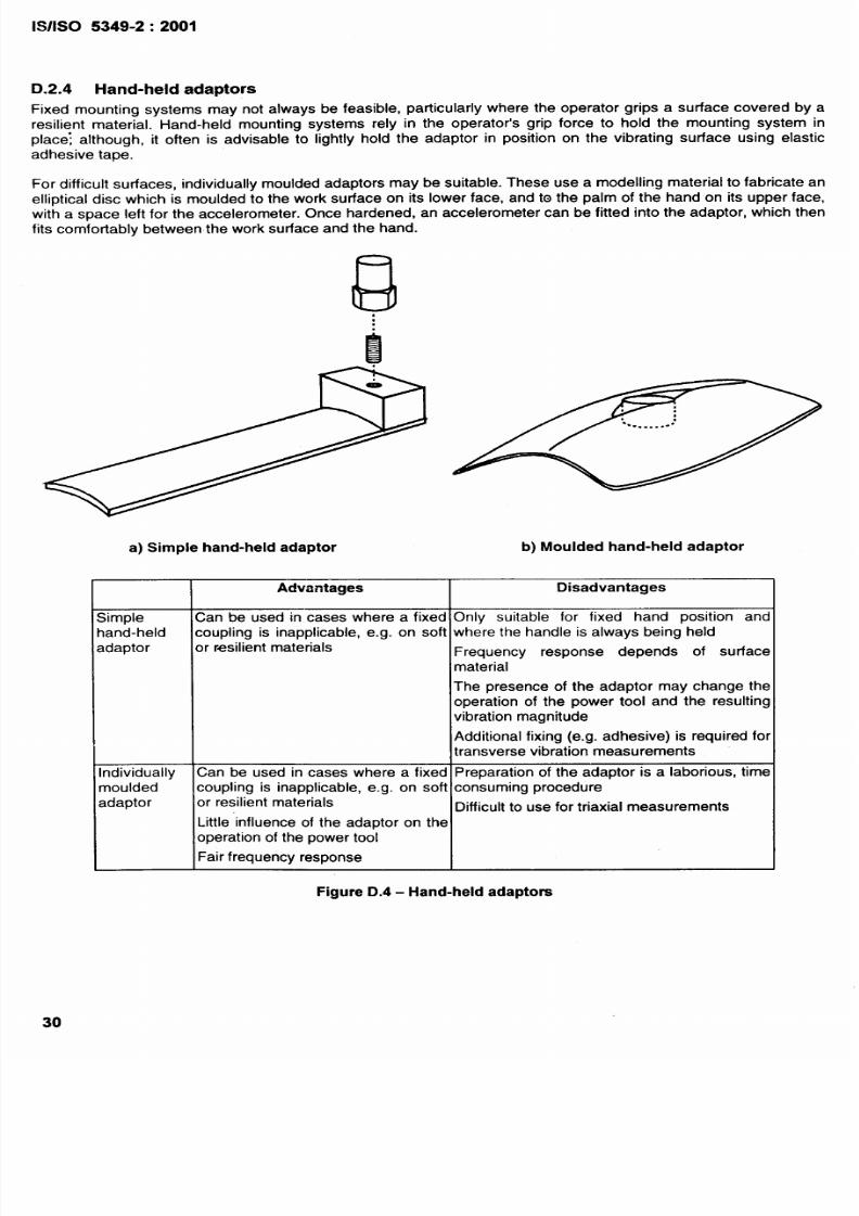
Measurements directly under the hand are usually only possible using special mounting adaptors (see annex D).
Such adaptors should fit under the hand, or between the fingers. For most practical measurements, the
accelerometers are mounted either side of the hand or on the underside of the tool handle adjacent to the middle of
the hand. With adaptors which fit between the fingers, the transducers should be mounted as close as possible to
the surface of the tool handle to minimize amplification of rotational vibration components. They should not have
any structural resonances which would affect the measured vibration.
It is possible to get differences in vibration measurement across the width of the hand, particularly for hand-held
power tools with side handles, such as angle grinders, and especially where these handles are flexibly mounted. In
these cases it is recommended that two accelerometers positions are used, located at the sides of the hand; the
average of the two vibration measurements is then used to estimate vibration exposure.
For many hand-held power tools, specific measurement locations and axes have been defined for the
measurement of vibration emission by ISO 8662 and other International Standards; these measurement locations
are summarized in annex A as examples of measurement locations. The measurement locations defined in
ISO 8662 are designed for a particular type of measurement (usually single axis only) and are not necessarily
suitable for the evaluation of vibration exposure. However, in some circumstances it may be appropriate to ensure
8/10/2019 is.iso.5349.2.2001
http://slidepdf.com/reader/full/isiso534922001 13/45
/1S0 5349-2:2001
hat workplace measurements of vibration are made using locations and axes compatible with those used for
ission measurements.
.1.4 Attaching accelerometers
General
he accelerometers should be rigidly attached to the vibrating surface. Annex D gives details of some mounting
ethods. A method shall be chosen which gives an adequate fixing to the vibrating surface, does not interfere with
he operation of the power tool and does not itself affect the vibration .charac teristics of the vibrating surface. The
ounting method chosen will be dependent on the particular measurement situation, each method has its own
vantages and disadvantages.
he mounting system should have a flat frequency response across the range of frequencies being measured, i.e.
it should not attenuate or amplify and should not have. any resonances in this frequency range. The mounting
system should be securely fitted to the vibrating surface, and all fixings should be carefully checked before and
after measurement.
The mounting of accelerometers on a power tool or hand-held workpiece is necessarily intrusive and will have
some effect on how the operator works. The mounting of the transducers should be arranged so that the operator
can work as normally as possible. It is important, prior to measurements, to observe how a power tool or hand-held
workpiece is held, to identify the best location and orientation of the accelerometers. The location (or locations) and
orientation of the transducers should be reported.
It is very important to avoid interfering with the power tool controls or with the safe operation of a power tool or
machine. It is often the case on power tools, that the best measurement location is where the on-off switch is
positioned. Care shall be taken to ensure that the power tool controls are not (and will not become) impeded by
transducers, mountings or cables.
6.1.4.2
Attaching to surfaces with resilient coatings
When a power tool handle has a soft outer coating the vibration transmission properties of the coating will be
dependent on the force with which the mounting system is attached. In such cases care shall be taken to ensure
that the measurement of vibration is not affected by the resilient material. if the coating is not thought to be
providing reduction in vibration exposure, either
remove the resilient material from the area beneath the transducers, or
– fix the transducers using a force which fully compresses the resilient material.
In most cases this approach will be adequate. However, it does not account for the vibration transmission
properties of the resilient coating.
Generally, resilient materials on power tool handles are not intended to provide vibration reduction but to provide a
good grip surface. Any resilient coatings will not usually affect the frequency-weighted vibration magnitude.
If the resilient coating may be providing some reduction in vibration exposure, for example, if it is a thick layer of
resilient material, then fix the transducer to an adaptor (see D.2.4) which is held against the vibrating surface by the
normal hand grip of the operator (the adaptor may be held in position using adhesive tape wrapped lightly around
the power tool handle and adaptor). This type of measurement is difficult, but it could give a better indication of the
actual vibration exposure.
NOTE
It is possible for poorly selected resilient materials to amplify the vibration at certain frequencies.
6.1.4.3
Attaching to handles or gripping zones constructed of lightweight, flexible materials
For power tools with handles or gripping zones constructed of lightweight, flexible materials, e.g. plastic side handle
on some sanders and grinders, adhesive may be used to attach low-mass accelerometers to the surface of the
material.
8
8/10/2019 is.iso.5349.2.2001
http://slidepdf.com/reader/full/isiso534922001 14/45
1S/1S0 5349-2:200
6.1.5 Accelerometer mass
Fixing accelerometers to a vibrating surface will affect the way the surface vibrates. The greater the mass fitted to
the surface, the greater the effect. If the total mass of accelerometer, or accelerometers, and mounting system is
small compared to the mass of the power tool, power tool handle or hand-held workpiece it is fitted to (less than
5 ?4. then the effect can be ignored.
NOTE Practical triaxial measurement systems of less than 30 g have been achieved.
If there is any doubt about the extent of the effect of the transducer’s mass then the following test should be used:
a) Attach the accelerometer(s) to the power tool handle or hand-held workpiece and make a measurement of
vibration magnitude.
b) Repeat the measurement with an additional mass, similar to that of the accelerometer, separately attached to
the power tool or hand-held workpiece, positioned next to the accelerometers.
c) If the magnitude of the vibration from the two measurements is markedly different a lighter accelerometer or
mounting system should be used.
6.1.6 Triaxial measurement
Triaxial measurement of vibration, using the basicentric coordinate system
However, there are some situations where triaxial measurement may not
defined in ISO 5349-1 is preferred.
be possible or necessary. In such
situations ISO 5349-1 requires that an appropriate multiplication factor is applied to a single- or two-axis
measurement result to give an estimated vibration total value.
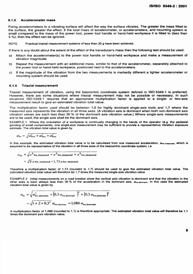
The multiplication factor used should be between 1,0 for highly dominant single-axis tools and 1,7 where the
measured axis represents the vibration in all three axes. (A vibration axis is dominant when both non-dominant axis
vibration values are each less than 30 YO of the dominant axis vibration value.) Where single-axis measurements
are to be used, the single axis shall be the dominant axis.
EXAMPLE 1 Where the orientation of a workpiece is continually changing in the hands of the operator (e.g. the pedestal
grinding of small components), one single-axis measurement may be sufficient to provide a representative vibration exposure
estimate. The vibration total value is given by
In this example, the estimated vibration total value is to be calculated from one measured acceleration, am,~a,ti, which is
assumed to be representative of the vibration in all three axes of the basicentric coordinate system, i.e.
ahv =
U 2 hw,measured + U 2 hw,memured t ~ 2 hw,measured
= ~c?hw,mem.red = l,73ahw,measured
Therefore a multiplication factor of 1,73 (rounded to 1,7) should be used to give the estimated vibration total value. The
estimated vibration total value will therefore be 1,7 times the measured single-axis vibration value.
EXAMPLE 2 Initial measurements on a road breaker show the vertical axis vibration is dominant and that the yibration in the
other axes is each always less than 30 ‘Io of the acceleration in the dominant axis, a~,dominant. In this case the estimated
vibration total value is given by
J
2
ahv = ahw. dommant
(
+ 0,3 abW~O~i”~l
T(
+ 0,3 ahW,~Omin~~
Y
d
1 + 2 x 0,32
ahW,dO~i,”l=
1,086
a~W,~O~in~,
A multiplication factor of 1,086 (rounded to 1,1) is therefore appropriate. The estimated vibration total value will therefore be 1,1
times the dominant axis vibration value.

8/10/2019 is.iso.5349.2.2001
http://slidepdf.com/reader/full/isiso534922001 15/45

8/10/2019 is.iso.5349.2.2001
http://slidepdf.com/reader/full/isiso534922001 16/45
1S/S0 5349-2:2001
6.1.11 Averaging times
Vibration magnitudes should be averaged over periods of normal use of the power tool, or periods of contact with a
hand-held workpiece. An r.m.s. average, using linear averaging, over one or more complete operations or work
cycles, should be used.
Exponential averaging should only be used where the vibration instrumentation does not allow linear averaging and
the vibration signal is steady enough to allow a reliable evaluation of average vibration value.
6.2 Sources of uncertainty in vibration measurement
6.2.1 Cable connector problems
The most common problem with the measurement of hand-transmitted vibration is ensyring that a reliable
connection is maintained with between the accelerometer and the signal cable. In general, care should be taken to
ensure that any cable connections are secure and that the cables have not been damaged in any way. In particular
at the connection to the accelerometer, great care should be taken to ensure that the cable and connector will not
be subjected to undue stresses as the power tool or hand-held workpiece is operated.
Faulty signal connections can show up simply as the loss of signal, in which case it appears that there is no
vibration. An intermittent loss of signal connection can show up as DC-offsets, between which the signal appears
normal.
Faulty cable screening connections can cause electrical pickup, introducing high levels of mains electricity
frequencies. For electrical tools, where the dominant vibration frequency is normally equal to or harmonically
related to the mains electricity frequency, it can be difficult to detect this type of fault. For piezoelectric
accelerometers, which use signal conditioning amplifiers with high impedance inputs, the loss of connection in the
cable earth screening can cause extreme pickup of electrical mains frequencies.
6.2.2 Electromagnetic interference
It is important to prevent electrical, magnetic or electromagnetic fields affecting the vibration measurement. In the
case of capacitively and inductively coupled interference signals, the effect of inevitable electromagnetic fields can
be reduced by the following means:
—
—
—
—
screening cables;
use of twisted cables;
earthing the signal cable’s screening at one end only, normally at the amplifier end;
provision of a connection to the transducer balanced to earth (e.g. by using a differential amplifier);
avoiding signal cables running parallel to power cables;
provision of electrical insulation between the accelerometer and the vibrating surface.
6.2.3 Triboelectric effect
Instrument cables should not be exposed to high-amplitude vibrational stress because, particularly in systems with
a high internal resistance (e.g. piezoelectric accelerometers), electrical signals are produced as a result of
deformation. For this reason signal cables should be secured to the vibrating surface, near to the accelerometer
(for example, using adhesive tape). For pneumatically powered hand tools, fixing the cables at regular intervals
along the air supply line is generally effective.
6.2.4 DC-shift
Exposing piezoelectric transducers to very high accelerations at high frequencies, for example on percussive tools
having no damping system, can cause the generation of DC-shift, where the vibration signal is disto&d such that a
false additional low-frequency component appears in the vibration signal. The DC-shift distortion occurs in the
transducer and is due to excitation of transients which are too large for the transducer, overloading the piezoelectric
system mechanically. A means to avoid DC-shift can be a mechanical filter, see annex C.
8/10/2019 is.iso.5349.2.2001
http://slidepdf.com/reader/full/isiso534922001 17/45
S/lSO 5349-2:2001
he presence of DC-shift is first noticeable in the low-frequency region below the percussive frequency; for this
eason DC-shift can usually be detected from a frequency analysis of the vibration signal. The distortion can show
n a frequency analysis unrealistically high values of low-frequency vibration. Converting the unweighed root-
ean-square (r.m.s.) acceleration,
a,
to displacement,
d,
using
d = a/ 40f2),
(where J is the centre frequency of
he frequency analysis band) will often provide an indication of whether DC-shift has occurred. If the displacement
alculated from the acceleration spectrum is clearly larger than the observed motion .of the transducer (e.g. greater
han twice the observed motion), it is likely that DC-shift has occurred.
If DC-shift has occurred, it is detected by examining the low-frequency components of the vibration signal.
However, the DC-shift distortion will affect the entire vibration spectrum. For this reason any measurements
showing signs of DC-shift should be disregarded; frequency-weighted. vibration values should not be determined
from spectra exhibiting DC-shift by removing or modifying low-frequency spectra bands.
6.3
Check and verification of the measurement chain
6.3.1 Regular checks of functionality
The whole measurement chain shall be checked, both before and after a sequence of measurements, by using a
vibration calibrator (a reference vibration source) which produces known sinusoidal acceleration at a known
frequency.
NOTE In practice, the sensitivity of accelerometers rarely drifts during measurements, however, they may suffer
mechanical failure. Therefore changes in apparent sensitivity should be noted and measurements discarded if necessa~.
6.3.2 Routine verification of the measurement system
The characteristics of the measurement system should be ‘verified on a regular basis (e.g. every 2 years). These
verification checks should ensure that the instrumentation is functioning within the tolerances defined in ISO 8041
(see also DIN 45671-3).
In addition to regular verification, the measurement system should be verified after rough handling of any important
part of the measurement system. The results of these verification checks shall be recorded.
7
Uncertainty of evaluation of daily vibration exposure
7.1 Acceleration measurement uncertainty
When measuring vibration transmitted to workers the uncertainty will be affected by factors related to individual
measurements, such as
instrumentation accuracy;
calibration;
electrical interference;
mounting of accelerometers;
mass of accelerometers;
location of accelerometers;
changes from the normal operation of the power tool and changes to hand posture and applied forces brought
about by the measurement process (i.e. mounting of accelerometers and associated cables);
changes in the operator’s method of working, as a response to being the subject of the measurement.
In addition uncertainty of the overall evaluation of vibration exposure will be affected by changes which occur in the
course of any working day, such as
changes in the condition of power tool and inserted tool (e.g. changing the wheel of a gfinder may change the
vibration transmitted to the operator dramatically);
changes in posture and applied forces;
changes in the characteristics of the materials being processed.

8/10/2019 is.iso.5349.2.2001
http://slidepdf.com/reader/full/isiso534922001 18/45
1S/1S0 5349-2:2001
NOTE 1 The uncertainty associated with instrumentation and calibration, electrical interference and mounting and mass of
accelerometers will usually be small compared with the uncertainties which arise from seletiion of measurement location and
variability in the work operation.
NOTE 2 When investigating the history of exposure of individuals it is desirable, if possible, to measure the vibration of
machines and inserted tools of different generations and different states of maintenance.
NOTE 3 When the purpose of the measurement is evaluation of vibration exposure associated with a specific task, the
differences between operators (variation in expertise, stature, etc.) may also be a source of uncefiainty (see 7.3).
7.2 Exposure time measurement uncertainty
The uncertainty of the estimation of exposure time is affected by the uncertainty of
measurements of the durations of exposure;
estimates of the number of work cycles per day;
– exposure time estimates supplied by the operators (see annex B), this may come from misinterpretation of the
question (confusion between usage of the power tool and real exposure to vibration), as well as poor estimates
of the durations for which exposure to vibration occurs (see 5.5).
7.3 Evaluation of uncertainties
The sources of uncertainty depend on the operation measured. The experimenter should determine the main
sources (e.g. wheel unbalance in the case of grinders) and multiple measurements should be made in order to
determine the extent of the uncertainty and to calculate the standard deviation regarding the dominant sources of
uncertainty (e.g. it may be useful to measure a grinding machine with wheels of different unbalance).
If the purpose of the measurement is not to evaluate the vibration exposure of a specific worker, but to evaluate the
exposure of a specific task, the evaluation of vibration exposure should, if possible, be based on measurements
using at least three different workers. The’ reported result shall be the arithmetic mean of the measurements, the
standard deviation should also be recorded.
8
Calculation of the daily vibration exposure
In many cases a worker’s daily vibration exposure comes from a number of operations. For each operation i, the
vibration total value, ahvl, and the exposure time to that source, ~1,shall be measured. The daily vibration exposure
A 8 , in m/s2, shall be obtained from
(1)
where
TOis the reference duration of 8 h (28800s)
n is the number of operations.
In order to facilitate comparison between different operations and to evaluate the individual contribution bf a
particular operation to the daily vibration exposure
A 8 ,
it may be useful to calculate the partial vibration exposure
for the individual operation, Ai 8), using
—
The daily vibration exposure is then given by
(2)
(3)
13

8/10/2019 is.iso.5349.2.2001
http://slidepdf.com/reader/full/isiso534922001 19/45
1s/1s0 5349-2:2001
A(8)
should be evaluated separately for both hands of the operator.
The uncertainties associated with the evaluation of A 8 are often high (e.g. 20% to 40 ‘Yo . Therefore, values of
A 8 should not normally be presented with more than two significant figures.
Practical applications of the calculation of the daily vibration exposure are given in annex E.
9
Information to k reported
The evaluation report shall refer to this part of ISO 5349 and provide; dependent on the situation investigated, the
following information:
a)
General information:
– company/customec
– purpose of the measurements (e.g. evaluation of vibration exposure of individual workers, worker groups,
evaluation of control measures, epidemiological study);
– date of evaluation;
—
subject or subjects of the individual exposure evaluation;
– person carrying out the measurements and evaluation.
b)
Environmental conditions at the workplace:
- location of measurements (e.g. indoor, outdoor, factory area);
– temperature;
- humidity;
– noise.
c) Information used to select the operations measured (see 5.2).
d)
Daily work patterns for each operation evaluated:
– description of operations measured;
machines and inserted tools used;
- materials or workplaces used;
– patterns of exposure (e.g. working hours, break periods);
—
information used to determine daily exposure times (e.g. work rate or numbers of work cycles or component:
per day, durations of exposure per cycle or hand-held workpiece).
e)
Details of vibration sources:
—
technical description of the power tool or machine;
—
type or model numbe~
age and maintenance condition of the power tool or machine;
weight of the hand-held power tool or hand-held workpiece;
vibration control measures on the machine or power tool, if any;
– type of hand grip used;
—
automatic control
systems
of the machine (e.g. torque control on nut runners);
—
power of the machine;
rotational frequency or percussive speed;

8/10/2019 is.iso.5349.2.2001
http://slidepdf.com/reader/full/isiso534922001 20/45
lS/lSO 5349-2:2001
—
—
9)
—
—
—
—
—
h)
—
—
i)
models and types of inserted tools;
any additional information (e.g. unbalance of inserted tools).
Instrumentation:
instrumentation detail;
calibration traceability;
date of most recent verification test;
results of functionality check;
results of any interference tests.
Acceleration measurement conditions:
accelerometer locations and orientations (including a sketch and dimensions);
methods of attaching transducers;
mass of the transducers and mount;
operating conditions;
arm posture and hand positions (including whether the operator is left- or right-handed);
any additional information (e.g. data on feed and grip forces).
Measurement results:
x-, y- and z-axis frequency-weighted hand-transmitted vibration values (ah~i~, ahWIYand ah~l~), possibly for
each operation;
measurement durations;
if frequency analysis is available, the unweighed frequency spectra;
if single- or two-axis measurements were used, the multiplying factors to give vibration total value estimates
(i~i~ding justification for using single- or two-axis measurements and justification for the multiplying factors
Daily vibration exposure evaluation results:
vibration total values, ahvl, for each operation;
duration of vibration exposure for each operation, T’i;
partial vibration exposures for each operation, z4i 8), if available;
daily vibration exposure,
A 8 ;
evaluation of the uncertainty of daily vibration exposure results.
15
8/10/2019 is.iso.5349.2.2001
http://slidepdf.com/reader/full/isiso534922001 21/45
1S/1S0 5349-2:2001
Annex A
(informative)
Examples of measurement locations
A.1
Introduction
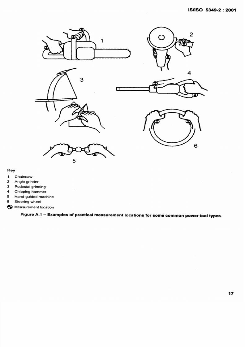
It is not always practical to make measurements at the surface of the hand(s) where the vibration enters the body in
the middle of the gripping zones as described in 6.1.3; for example, on power tools with a closed or open bow grip
or a pistol grip, the location of the trigger may make measurement halfway along the handle impossible. In practice,
the measurement location usually has to be to one side of the hand. The location of power controls and hand
guards may also affect where it is possible to fix accelerometers. Figure A.1 shows examples of measurement
locations for some common power tools.
A.2 Measurement locations used in vibration type test standards
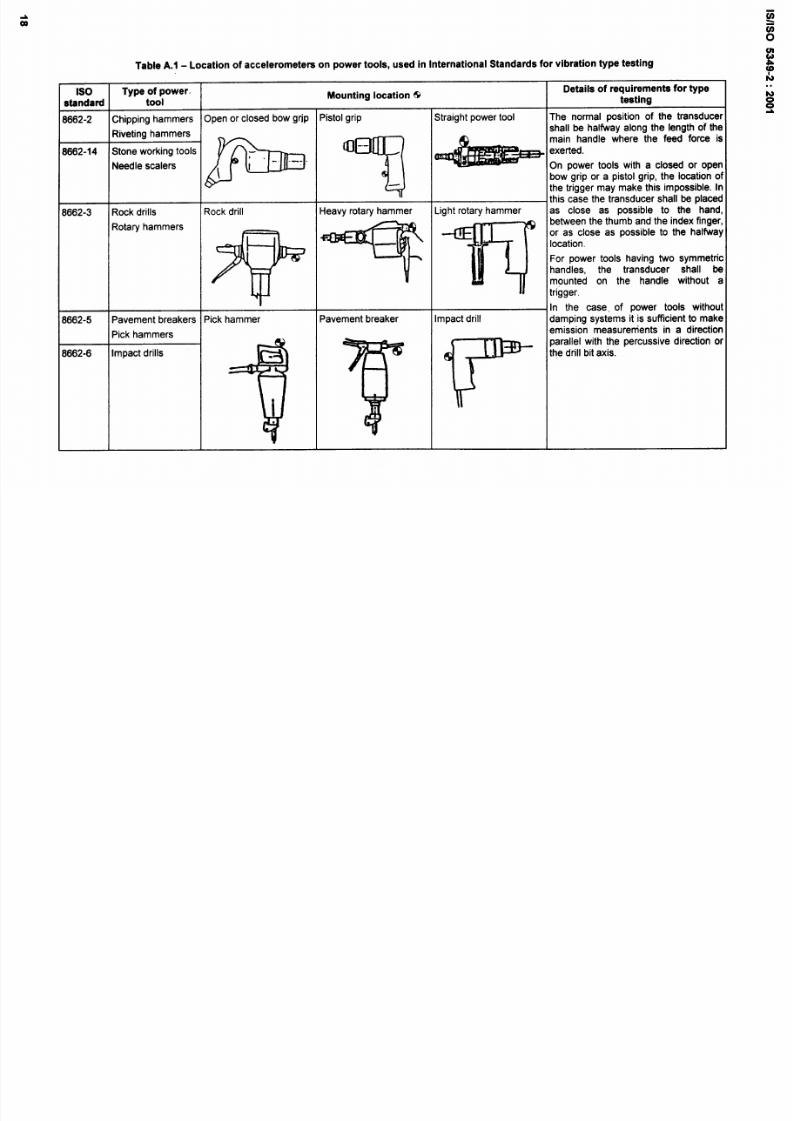
Table A. 1 lists, as examples, the measurement locations specified in LSO 8662-2 to ISO 8662-14, ISO 7505 and
ISO 7916 which specify laboratory methods for measuring the vibration at the handles of different hand-held power
tools for the purpose of determining vibration emission values.
The locations shown in Table A.1 are good solutions, but may not be appropriate for the measurement of the
exposure. The objectives of an exposure measurement are very different to those of a type test. For evaluation of
vibration exposure, the location of the accelerometers shall be based on where the hand actually holds the power
tool, rather than where the power tool is held during a type test. The principal requirement of the vibration type test
standards is that measurements are made in the main gripping zone where the operator normally holds the power
tool and applies the feed force. In general the type test standards identify only one measurement location and axis.
The examples listed in Table A.1 apply to tools having rigid handles or grip zones (see 6.1.4 for elastically mounted
handles).
8/10/2019 is.iso.5349.2.2001
http://slidepdf.com/reader/full/isiso534922001 22/45
s%-
ff \
3
1S/1S0 5349-2:2001
4
5
Chainsaw
Angle grinder
Pedestal grinding
Chipping hammer
Hand-guided machine
Steering wheel
Measurement location
Figure A.1
- Exarhples of practical measurement locations for some common power tool types
8/10/2019 is.iso.5349.2.2001
http://slidepdf.com/reader/full/isiso534922001 23/45
Table A.1 - Location of accelerometers on power tools, used in International Standards for vibrat ion type testing
1s0
Type of power
Mounting locat ion @
Details of requirements for type
standard
tool
testing
8662-2
Chipping hammers
Open or closed bow grjp
Pistol grip
Straight power tool
The normal position of the transducer
Riveting hammers
shall be halfway along the length of the
8662-14 Stone working tools
*“
‘“y
-
‘Xeded’
main handle where the feed force is
Needle scalers On power tools with a closed or open
bow grip or a pistol grip, the location of
the trigger may make this impossible. In
this case the transducer shall be placed
8662-3
Rock drills
Rock drill
Heavy rotary hammer Light rotary hammer
as close as possible to the hand,
Rotary hammers
between the thumb and the index f inger,
p
T
~
;;;;thetansducesha~
or as close as possible to the halfway
For power tools having two symmetric
mounted on the handle without a
In the case, of power tools withoul
8662-5
Pavement breakers
Pick hammer
Pavement breaker Impact drill
damping systems it is sufficient to make
Pick hammers
emission measurements in a direction
~ ~
~.
thedrillbitaxis.
parallel with the percussive direction or
8662-6
Impact drills
8/10/2019 is.iso.5349.2.2001
http://slidepdf.com/reader/full/isiso534922001 24/45
1s0 Type of power
Mounting location &
Detai ls of requirements for type
standard tool
testing
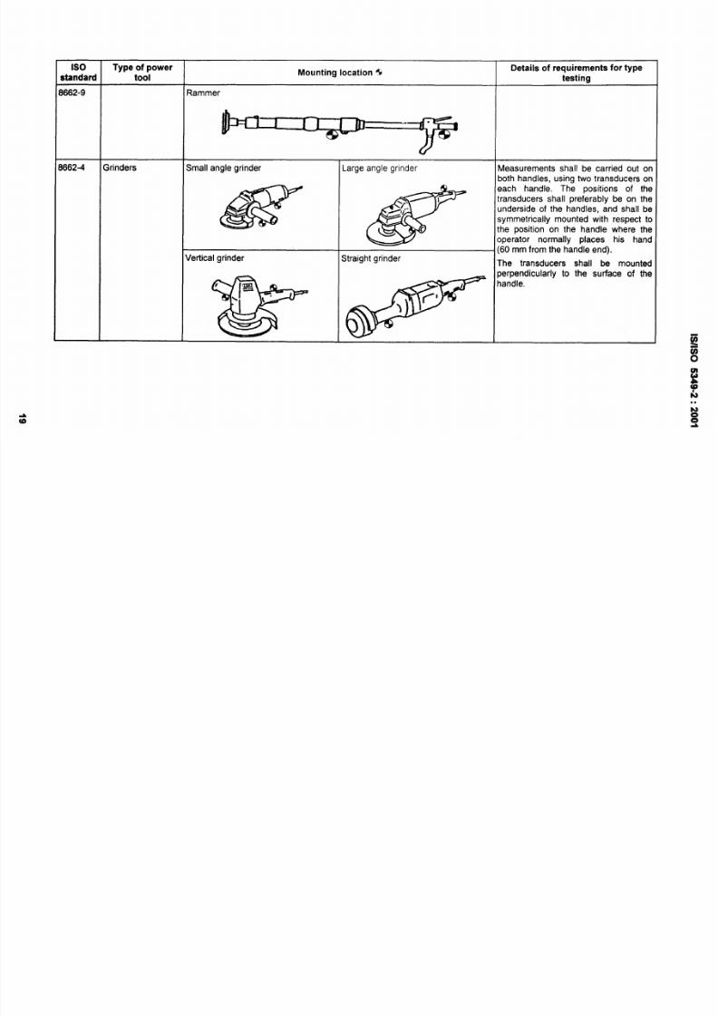
1662-9 Rammer
1 —n
‘“9
3662-4 Grinders
Small angle grinder Large angle grinder
Measurements shall be carried out on
both handles, using two transducers on
N
@
(60mrn~omthehandleend).
each handle, The positions of the
transducers shall preferably be on the
underside of the handles, and shall be
symmetr ically mounted with respect to
the position on the handle where the
operator normally places his hand
Vertical grinder
Straight grinder
The transducers shall be mounted
w
perpendicularly to the surface of the
8
I
-=
handle.
.=
\
I
{“
c’
)

8/10/2019 is.iso.5349.2.2001
http://slidepdf.com/reader/full/isiso534922001 25/45
1s0
standard
1662-7
Type
of
power
tool
I
Mounting location @
1
Nrenches
Straight power tool
Screwdrivers
Wt runners
Pistol handle
VF
e
6
.
.
Angled power tool
Bow handle
Details of requirements for type
testina
Measurements shall be made at the
locat ions i llustrated in the f igures on the
handle(s) where the operator normally
holds the power tool. The normal
position of the transducer shall be
halfway along the length of the handle.
If the placing of the trigger makes this
impossible, then the transducer shall be
placed as close as possible to this
position.
For straight control-handle power tools,
the transducer shall be located so as to
measure the acceleration on the power
tool surface in a tangential direction
relative to the ,motor shaft. The
transducer shall be located as close as
possible to the surface of the power
tool.
8/10/2019 is.iso.5349.2.2001
http://slidepdf.com/reader/full/isiso534922001 26/45
1s0
Type of
power
Mounting locat ion @
Details of requirements for type
standard
tool
testing
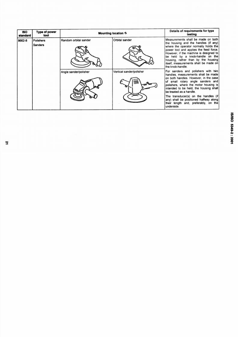
3882-8
Polishers
Random orbital sander
Orbital sander
Measurements shall be made on both
Sanders
the housing and the handles (if any)
&
&
~e~~.~d~knob-hand’eonthe
where the operator normally
holds the
power tool and applies the feed force.
However, if the machine is designed to
housing, rather than by the housing
itself, measurements shall be made on
Angle sander/polisher
Vertical sander/polisher
For sanders and polishers with MO
handles, measurements shall be made
@
,=
\
on both handles. However, in the case
t
I
~
of small rotary angle sanders and
/’ “
\
1
1
polishers, where the motor housing is
I
intended to be held, the housing shall
*
be treated as a handle.
The transducer(s) on the handles (if
any) shall be positioned halfivay along
their length and, preferably, on the
underside.
8/10/2019 is.iso.5349.2.2001
http://slidepdf.com/reader/full/isiso534922001 27/45
1s0
Type of power
Mounting location @
Details of requirements for type
~tandard tool
testing
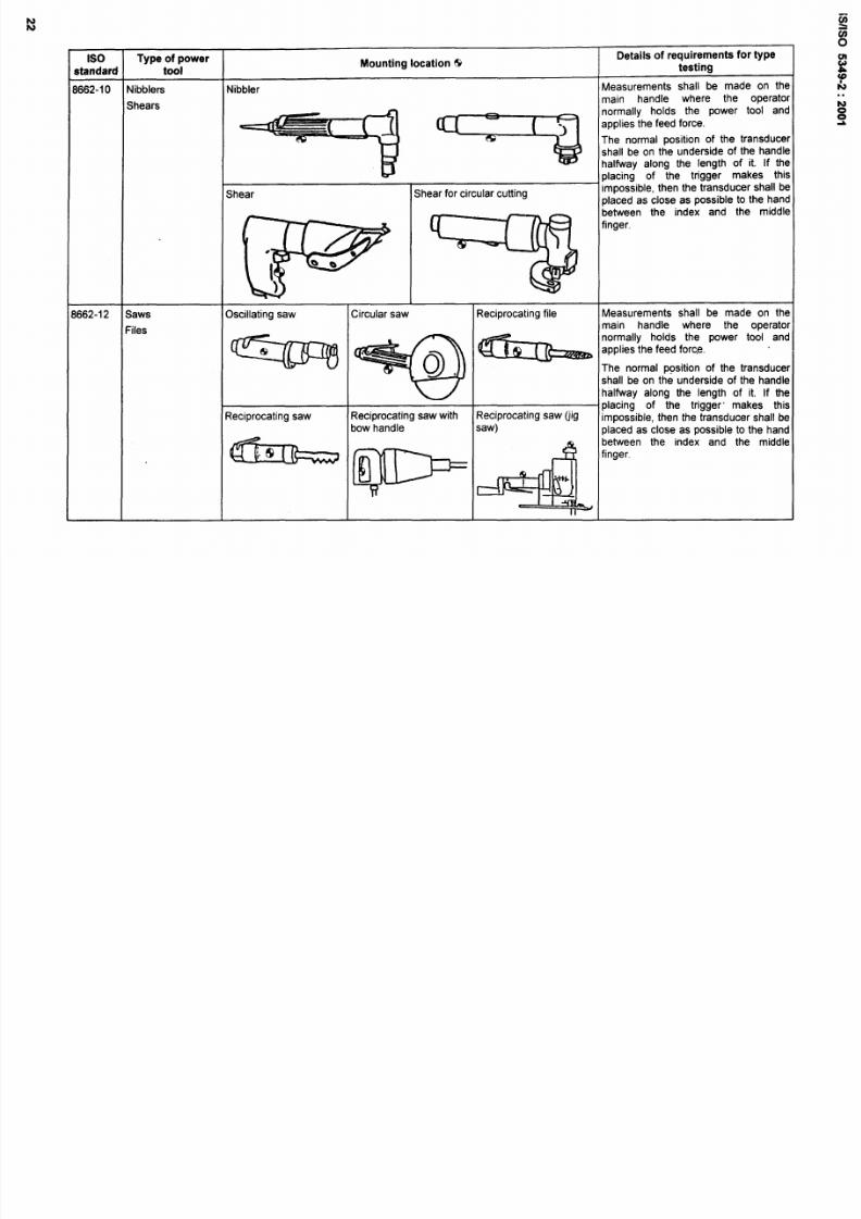
1662-10
Nibblers
Nibbler
Measurements shall be made on the
Shears
main handle where the operator
normally holds the power tool and
“-q
Y
app’iesthe feed force”
The normal position of the transducer
shall be on the underside of the handle
halfway along the length of it. If the
placing of the trigger makes this
Shear Shear for circular cutting
impossible, then the transducer shall be
placed as close as possible to the hand
between the index and the middle
finger,
&
1662-12
Saws
Oscillating saw
Circular saw Reciprocating file
Measurements shall be made on the
Files
main handle where the operator
-
w
““b
normally holds the power tool and
&
““~
~
applies the feed force.
The normal position of the transducer
.
shall be on the underside of the handle
halfway along the length of it. If the
placing of the trigger” makes this
Reciprocating saw Reciprocating saw with
Reciprocating saw (jig
impossible, then the transducer shall be
bow handle
saw)
placed as close as possible to the hand
between the index and the middle
-
P
4
‘inger”

8/10/2019 is.iso.5349.2.2001
http://slidepdf.com/reader/full/isiso534922001 28/45

8/10/2019 is.iso.5349.2.2001
http://slidepdf.com/reader/full/isiso534922001 29/45
s
Type of power
Mounting location 19
Detai ls of requirements for type
standard tool
testing
?505
Chain saws
The accelerometers shall be positioned
as near the operator’s hands as
possible without obstructing the normal
grip. The centre of gravity of the
accelerometers shall not be more than
20 mm away from the nearest hand.
’916
Brush-saws
I
8/10/2019 is.iso.5349.2.2001
http://slidepdf.com/reader/full/isiso534922001 30/45
lS/lSO 5349-2:2001
Annex B
(informative)
Evaluation of vibration exposure over periods greater than one day
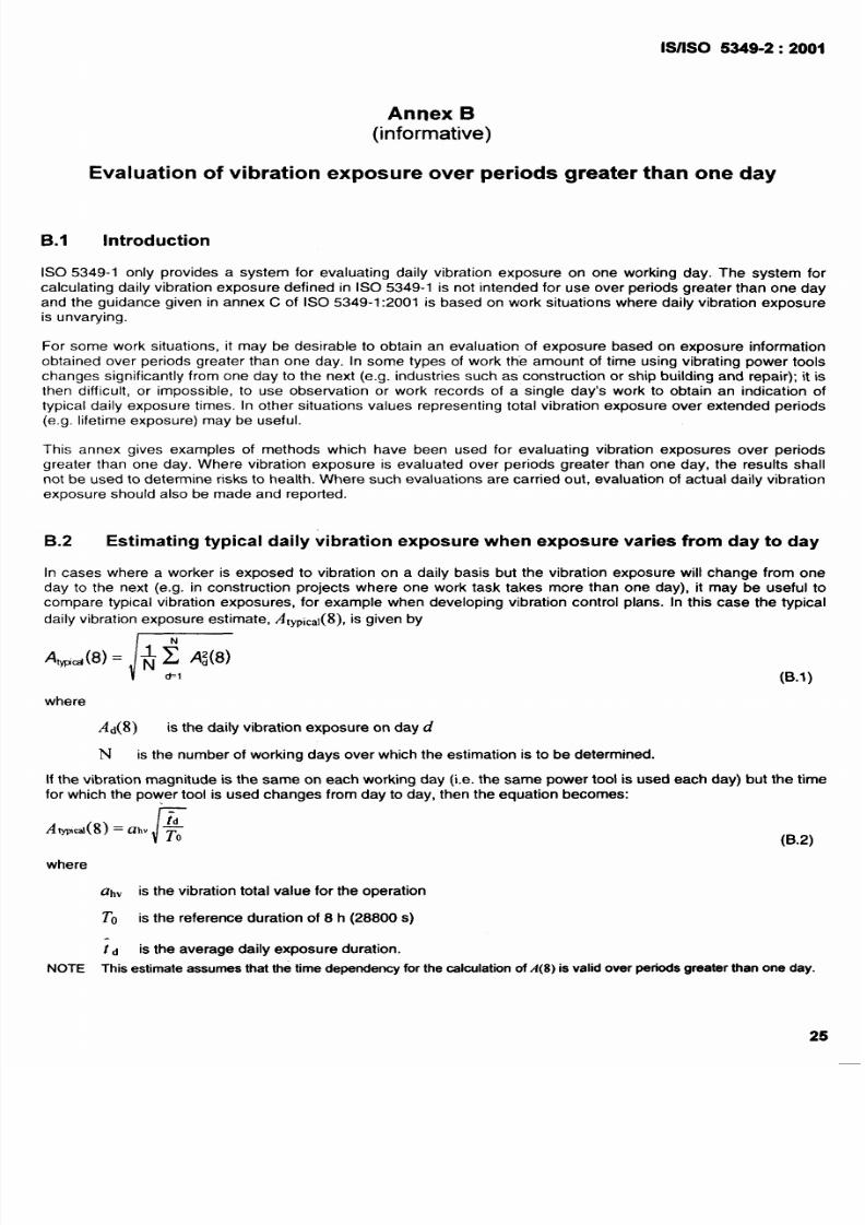
B.1 Introduction
ISO 5349-1 only provides a system for evaluating daily vibration exposure on one working day. The system for
calculating daily vibration exposure defined in ISO 5349-1 is not intended for use over periods greater than one day
and the guidance given in annex C of ISO 5349-1:2001 is based on work situations where daily vibration exposure
is unvarying.
For some work situations, it may be desirable to obtain an evaluation of exposure based on exposure information
obtained over periods greater than one day. In some types of work the amount of time using vibrating power tools
changes significantly from one day to the next (e.g. industries such as construction or ship building and repair); it is
then difficult, or impossible, to use observation or work records of a single day’s work to obtain an indication of
typical daily exposure times. In other situations values representing total vibration exposure over extended periods
(e.g. lifetime exposure) may be useful.
This annex gives examples of methods which have been used for evaluating vibration exposures over periods
greater than one day. Where vibration exposure is evaluated over periods greater than one day, the results shall
not be used to determine risks to health. Where such evaluations are carried out, evaluation of actual daily vibration
exposure should also be made and reported.
B.2 Estimating typical daily vibration exposure when exposure varies from day to day
In cases where a worker is exposed to vibration on a daily basis but the vibration exposure will change from one
day to the next (e.g. in construction projects where one work task takes more than one day), it may be useful to
compare typical vibration exposures, for example when developing vibration control plans. In this case the typical
daily vibration exposure estimate, AtYPiC~l(8),is given by
(B.1)
where
Ad 8)
is the daily vibration exposure on day d
N is the number of working days over which the estimation is to be determined.
If the vibration magnitude is the same on each working day (i.e. the same power tool is used each day) but the time
for which the power tool is used changes from day to day, then the equation becomes:
/-
/ltypcaI 8)= ah,
(B.2)
where
ah” is the vibration
tOtal VahJt?
for the operation
To is the reference duration of 8 h (28800s)
id
is the average daily exposure duration.
NOTE This estimate assumes that the time dependency for the calculation of A(8) is valid over periods greater than one day.

8/10/2019 is.iso.5349.2.2001
http://slidepdf.com/reader/full/isiso534922001 31/45

8/10/2019 is.iso.5349.2.2001
http://slidepdf.com/reader/full/isiso534922001 32/45
ISIISO 5349-2:2001-
Annex C
(informative)
Mechanical filters
General
he risk of DC-shift distortion in piezoelectric accelerometers (see 6.2.4) can be reduced by the careful selection of
ccelerometers (see 6.1 .2). However, when measuring on percussive or roto-percussive power tools, or in case of
oubt, a mechanical filter fitted between the transducer and the vibration source is recommended. Such a filter
educes the very high frequency content of the transients, and prevents the mechanical’ overloading of the
iezoelectric system. The mechanical filter acts as a low-pass filter attenuating the frequencies which cause DC-
hift, while vibration in the frequency range of interest is not influenced.
OTE
The DC-shift is a distortion brought about by the charge-coupling of piezoelectric accelerometers. Other
ccelerometer types, such as piezoresistive accelerometers, are not affected by DC-shift. Therefore, the use of mechanical
ilters to prevent DC-shift is only necessa~ when using piezoelectric accelerometers.
Mechanical filters may also be useful in reducing the influence of unwanted high-frequency vibration on the
accelerometer, preventing signal-processing overloads caused by high-frequency acceleration signals or allowing
more sensitive accelerometers to be used than would be possible without the mechanical filter.
C.2
Selection
A mechanical filter shall be suitable for the accelerometer. The cut-off frequency of the mechanical filter is
influenced by the mass of the accelerometer. Mechanical filters are available from some transducer manufacturers,
or can be constructed using suitable resilient materials. For lightweight transducers (around 2 g), a simple thin layer
of resilient material below the transducer mount is likely to be sufficient.
The mechanical filter should not alter the frequency response characteristics of the measurement system in the
frequency range of interest, i.e. there should be no amplification or attenuation of vibration signals below 1250 Hz,
and the additional mass of the mechanical filter should not alter the vibration characteristics of the vibrating surfacd.
Comparative measurements with and without the mechanical filter on a power tool which does not produce DC-sh$l
can be used to assess the frequency response of a mechanical filter.
The system consisting of mechanical filter and transducer shall be as compact as possible so as to ensure that the
centre of the transducer is as close as possible to the vibrating surface.
It is not advisable to mount a three-directional transducer system onto one mechanical filter.
C.3
Use on axes perpendicular to the percussive axis
A mechanical filter is generally only needed to avoid DC-shift in measurements of acceleration along the dominant
axis of vibration, i.e. along the percussive axis of percussive or impact power tools.
Where DC-shift is a problem along a non-dominant axis of a percussive power tool, mechanical filters shoul~ be
used with caution; in such cases mechanical filters may increase the apparent transverse sensitivity to vibraticjn by
allowing excessive rotational motion of the accelerometer. Accelerometers should be fitted with their directidm of
minimum transverse sensitivity aligned to the percussive axis to minimize any effect due to rotational motion.
8/10/2019 is.iso.5349.2.2001
http://slidepdf.com/reader/full/isiso534922001 33/45
1S/1S0 5349-2:2001
Guidance on
D.1
Introduction
Annex D
(informative)
mounting accelerometers
To fix accelerometers to vibrating surfaces different mounting methods have been developed. In Figures D.1 to D.4
some mounting methods are shown, together with the circumstances in which they can be applied and the
advantages and disadvantages associated with them. These examples were selected because of their flat
frequency response in the frequency range of interest. For further guidance, see ISO 5348.
D.2
Mounting methods
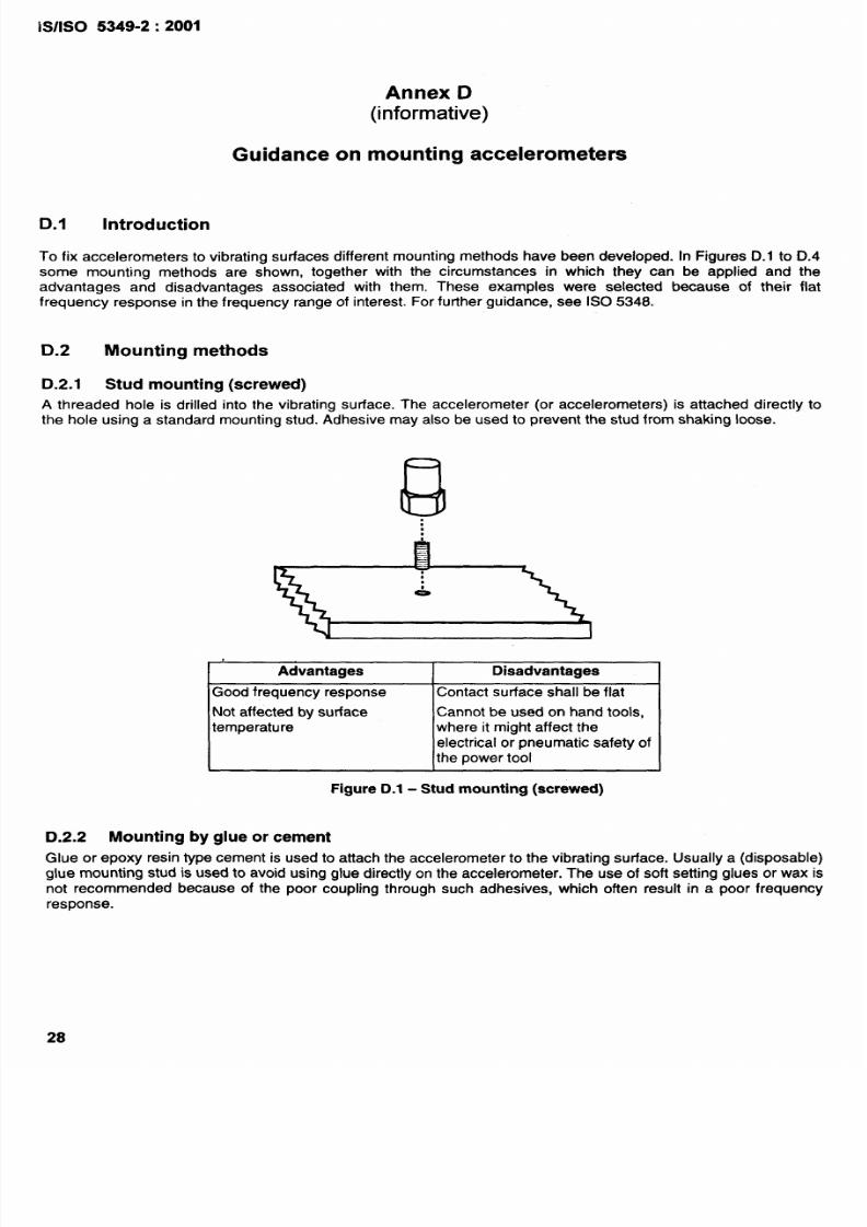
D.2.1 Stud mounting (screwed)
A threaded hole is drilled into the vibrating surface. The accelerometer (or accelerometers) is attached directly to
the hole using a standard mounting stud. Adhesive may also be used to prevent the stud from shaking loose.
,
Advantages
Disadvantages
Good frequency response
Contact surface shall be flat
Not affected by surface
Cannot be used on hand tools,
temperature
where it might affect the
electrical or pneumatic safety of
the power tool
Figure D.1 - Stud mounting (screwed)
D.2.2 Mounting by glue or cement
Glue or epoxy resin type cement is used to attach the accelerometer to the vibrating surface. Usually a (disposable)
glue mounting stud is used to avoid using glue directly on the accelerometer. The use of soft setting glues or wax is
not recommended because of the poor coupling through such adhesives, which often result in a poor frequency
response.
28

8/10/2019 is.iso.5349.2.2001
http://slidepdf.com/reader/full/isiso534922001 34/45
1S/1s0 5349-2:2001
F1
E
lue
Cement/
epoxy resin
M
*
Advantages
Disadvantages
Good frequency response
Contact surface shall be flat and
clean
Good frequency response Contact surface shall be clean
Fits to uneven surfaces
Figure D.2 - Mounting by glue or cement
.2.3 Clamp connections
e accelerometers are attached to a lightweight mounting block. The block is held against the vibrating surface by
flexible strap. Metal or nylon straps have been successfully used. Nylon cable ties should be of a type which can
e fastened tightly (ratchet type reusable cable ties are not suitable). Care should be taken to ensure that any
sonance frequencies of the mounting assembly are high enough above the upper limit of the measurement
equency range.
R
a) Metal “U” clamp (with metal strap)
b) With nylon strap or metal hose-clip
Advantages
Disadvantages
Metal “U” clamp Suitable for triaxial measurements
Bulky and heavy
(with metal strap)
With nylon strap or Rapid mounting
M~nly limited to measurement or
metal hose-clip
Suitable for triaxial measurements
power tool handles
Light
No sharp edges
Figure D.3 - Clamp connections
8/10/2019 is.iso.5349.2.2001
http://slidepdf.com/reader/full/isiso534922001 35/45
8/10/2019 is.iso.5349.2.2001
http://slidepdf.com/reader/full/isiso534922001 36/45
1S/1S0 5349-2:2001
Annex E
(informative)
Examples of the calculation of daily vibration exposure
.1 Introduction
his annex gives some examples of the organization and calculation of 8-h energy-equivalent vibration total value
daily vibration exposure), A(8), according to clause 8. The examples are related to the measurement procedures
pecified in 5.3.
n all the worked examples given in this annex:
acceleration magnitudes are assumed to be averaged vibration total values;
only one vibration exposure figure is calculated, normally separate evaluations are needed for the left and right
hands;
little variation in vibration magnitude is shown within periods of exposure, normally larger variations would be
common, and some averaging of sample vibration measurements would be required.
2
Examples of the use of single power tools
.2.I Long-term measurement
of
continuous tool operation
his is the simplest measurement situation: The power tool is operated continuously for long periods and the hand
s always in contact with the power tool or hand-held workpiece during use. Examples of this type of operation are
evelling a large area using a vibrating plate tamper, floor polishing and ride-on lawn mowers.
In this case
the measurements of vibration magnitude can be made over long periods, which will give good, representative
values;
the exposure time is the time for which the power tool is used.
) Advantages
The vibration magnitude may be applied easily to vibration exposure evaluations in other situations, where the
exposure times may be different.
b) Disadvantages
There are no real disadvantages to this type of measurement, but, in practice, there are not many cases
where it is possible.
EXAMPLE During a working day, a vibrating plate tamper is used for a total of 2,5 h, no other vibrating tools are used. The
vibration exposure pattern is similar to that shown in Figure E.1. The arithmetic average of three measurements-of the vibration
on the power tool handles indicates that the vibration total value, ah., is 7,4 rnk z.

8/10/2019 is.iso.5349.2.2001
http://slidepdf.com/reader/full/isiso534922001 37/45
1S/1S0 5349-2:2001
The daily vibration exposure, A(8), isgiven by equation (1) which for single exposure is:
4
.7, +
~tlv
-—-
(E.I)
=4, lm s
M
M3
2
Key
1 Measurement duration
2 Operating time (= exposure time)
3 Time
4 ahv,meas.red .
Figure E.1 - Long-term measurement of continuous exposures
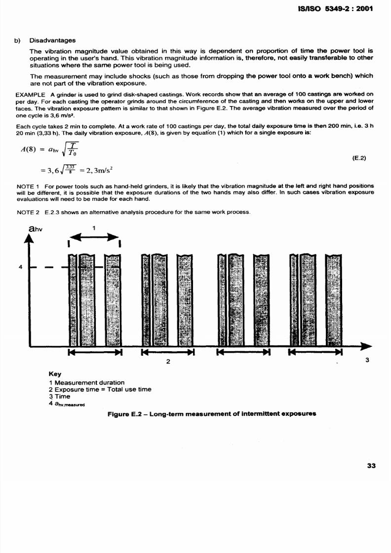
E.2.2 Long-term measurement of intermittent tool operation
For many power tools, the hand is always in contact with the power tool or hand-held workpiece during use, but the
power tool is not operated continuously, there are short breaks in operation when it is used. Examples of this type
of operation include the use of grinders, chain saws and scaling hammers.
If the power tool is being operated for most of the period of use, one option is:
– to carry out a long-term measurement of vibration magnitude over a representative period of use, in which case
– the exposure time is the time for which the power tool is used during the working day.
a) Advantages
The vibration magnitude is representative of the actual task, including periods when the machine is building up
to operating speed and running back down to idling or off (periods which may not be included in other
methods).
8/10/2019 is.iso.5349.2.2001
http://slidepdf.com/reader/full/isiso534922001 38/45
lS/lSO 5349-2:2001
b)
Disadvantages
The vibration magnitude value obtained in this way is dependent on proportion of time the power tool is
operating in the user’s hand. This vibration magnitude information is, therefore, not easiiy transferable to other
situations where the same power tool is being used.
The measurement may include shocks (such as those from dropping the power tool onto a work bench) which
are not part of the vibration exposure.
EXAMPLE A grinder is used to grind disk-shaped castings. Work records show that an average of 100 castings are worked on
per day. For each casting the operator grinds around the circumference of the casting and then worka on the upper and lower
faces.
The vibration exposure pattern is similar to that shown in Figure E.2. The averagevibrationmeasuredover the periodof
one cycle is3,6 rrhz.
Each cycle takes 2 min to complete. At a work rate of 100 castings per day, the total daily exposure time is then 200 rein, i.e. 3 h
20 min (3,33 h). The daily vibration exposure, A(8), is given by equation (1) which for a single exposure is:
(E.2)
=3,6~ =2,3MIS2
NOTE 1 For power tools such as hand-held grinders, it is likely that the vibration magnitude at the left and right hand positions
will be different, it is possible that the exposure durations of the two hands may also differ. In such cases vibration exposure
evaluations will need to be made for each hand.
NOTE 2 E.2.3 shows an alternative analysis procedure for the same work process.
2
3
Key
1 Measurement duration
2 Exposure time= Total use time
3 Time
4 ab,ma~wti
Figure E.2 - Long-term measurement of intermittent exposures
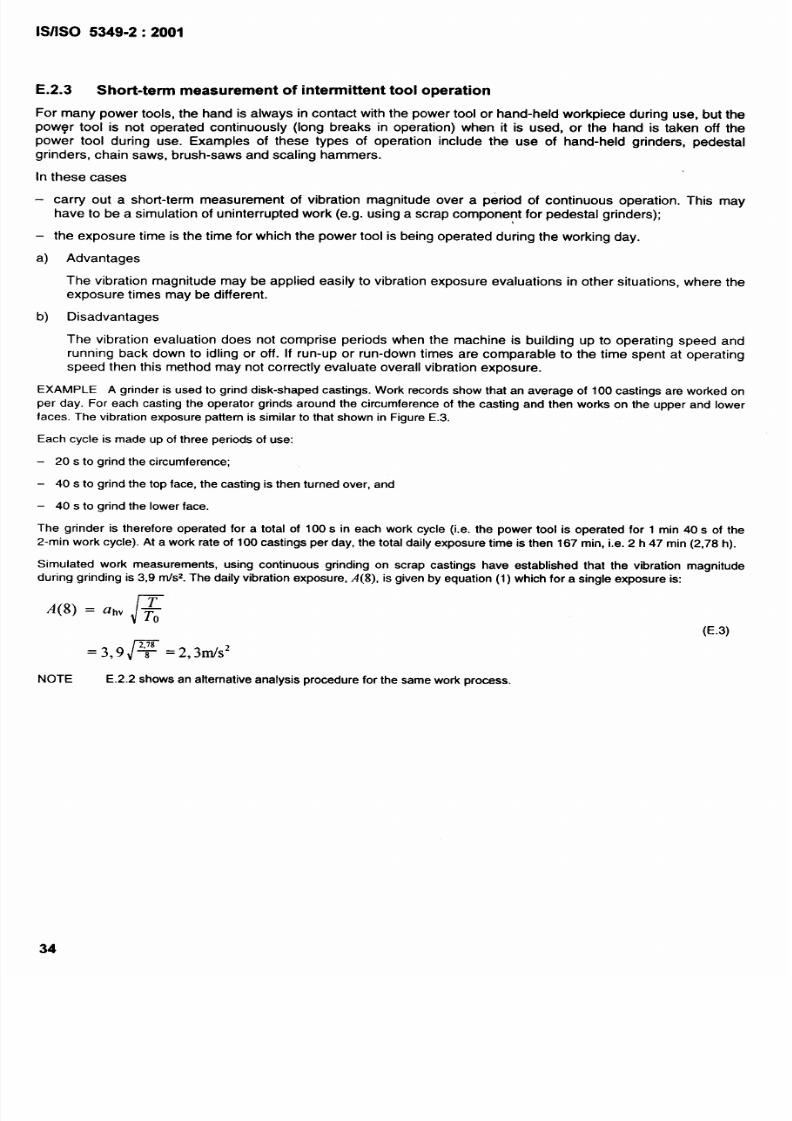
8/10/2019 is.iso.5349.2.2001
http://slidepdf.com/reader/full/isiso534922001 39/45
1s/1s0
E.2.3
5349-2:2001
Short-term measurement of intermittent tool operation
For many
power tools, the hand is always in contact with the power tool or hand-held workpiece during use, but the
powqr tool is not operated continuously (long breaks in operation) when it is used, or the hand is taken off the
power tool during use. Examples of these types of operation include the use of hand-held grinders, pedestal
grinders, chain saws, brush-saws and scaling hammers.
In these cases
–
carry
out a short-term measurement of vibration magnitude over a period of continuous operation. This may
have to be a simulation of uninterrupted work (e.g. using a scrap component for pedestal grinders);
– the exposure time is the time for which the power tool is being operated during the working day.
a) Advantages
The vibration magnitude may be applied easily to vibration exposure evaluations in other situations, where the
exposure times may be different.
b)
Disadvantages
The vibration evaluation does not comprise periods when the machine is building up to operating speed and
running back down to idling or off. If run-up or run-down times are comparable to the time spent at operating
speed then this method may not correctly evaluate overall vibration exposure.
EXAMPLE A grinder is used to grind disk-shaped castings. Work records show that an average of 100 castings are worked on
per day. For each casting the operator grinds around the circumference of the casting and then works on the upper and lower
faces. The vibration exposure pattern issimilar to that shown in Figure E.3.
Each cycle is made up ofthree periods of use:
– 20 s to grind the circumference;
– 40s to grind the top face, the casting is then turned over, and
– 40 s to grind the lower face.
The grinder is therefore operated for a total of 100s in each work cycle (i.e. the power tool is operated for 1 min 40s of the
2-rein work cycle). At a work rate of 100 castings per day, the total daily exposure time is then 167 rein, i.e. 2 h 47 min (2,78 h).
Simulated work measurements, using continuous grinding on scrap castings have established that the vibration magnitude
during grinding is 3,9 rrdsz.The daily vibration exposure,
A(8), is
given by equation (1) which for a single exposure is:
(E.3)
=3,9@ =2,3mls2
NOTE E.2.2 shows an alternative analysis procedure for the same work process.
34
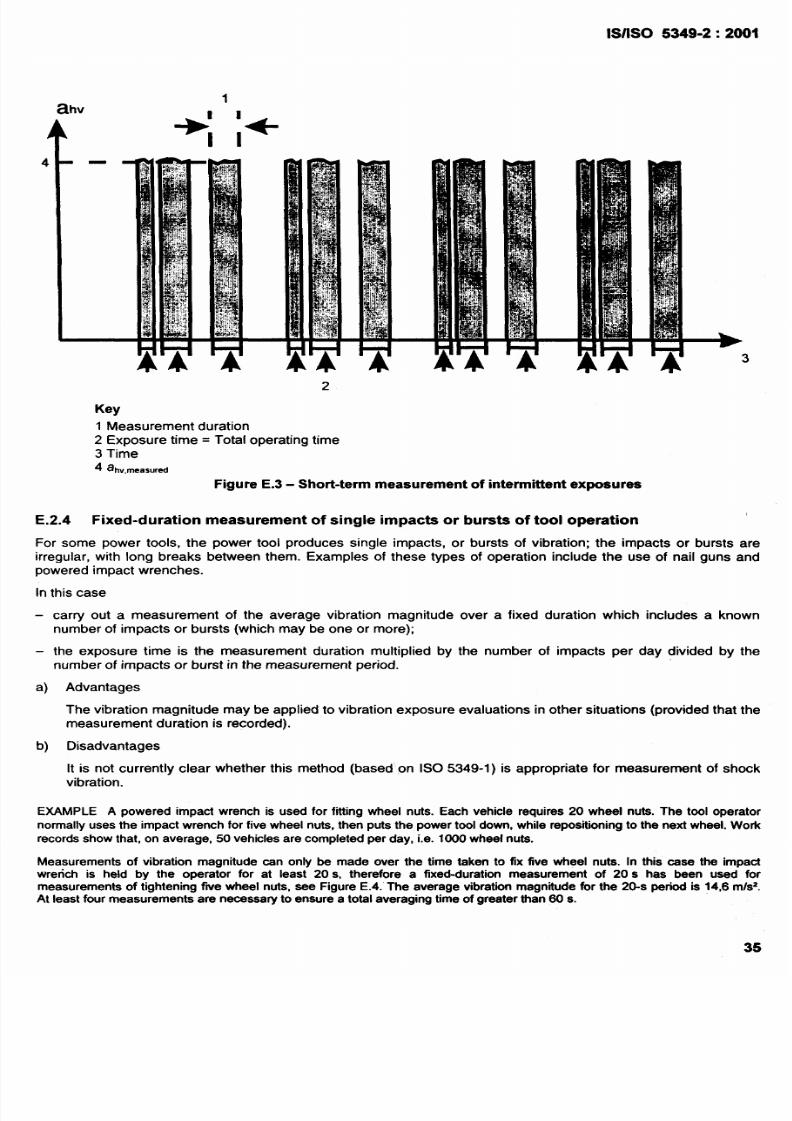
8/10/2019 is.iso.5349.2.2001
http://slidepdf.com/reader/full/isiso534922001 40/45
lS/lSO 5349-2:2001
-
2
Key
1 Measurement duration
2 Exposure time= Total operating time
3 Time
4 ahv,~~~~u,~
Figure E.3 - Short-term measurement of intermittent exposures
E.2.4 Fixed-duration measurement of single impacts or bursts of tool operation
For some power tools, the power tool produces single impacts, or bursts of vibration; the impacts or bursts are
irregular, with long breaks between them. Examples of these types of operation include the use of nail guns and
powered impact wrenches.
In this case
carry out a measurement of the average vibration magnitude over a fixed duration which includes a known
number of impacts or bursts (which may be one or more);
– the exposure time is the measurement duration multiplied by the number of impacts per day divided by the
number of impacts or burst in the measurement period.
a) Advantages
The vibration magnitude may be applied to vibration exposure evaluations in other situations (provided that the
measurement duration is recorded).
b) Disadvantages
It is not currently clear whether this method (based on ISO 5349-1) is appropriate for measurement of shock
vibration.
EXAMPLE A powered impact wrench is used for fitting wheel nuts. Each vehicle requires 20 wheel nuta. The tool operator
normally uses the impact wrench for five wheel nuts, then puts the power tool down, while repositioning to the next wheel. Work
records show that, on average, 50 vehicles are completed per day, i.e. 1000 wheel nuts.
Measurements of vibration magnitude can only be made over the time taken to fix five wheel nuts. In this case the impact
wrench is held by the operator for at least 20s, therefore a fixed-duration measurement of 20s has been used for
measurements of tightening fwe wheel nuts, see Figure E.4. The average vibration magnitude for the 20-s period is 14,6 m/s2.
At least four measurements are necessary to ensure a total averaging time of greater than 60s.

8/10/2019 is.iso.5349.2.2001
http://slidepdf.com/reader/full/isiso534922001 41/45
8/10/2019 is.iso.5349.2.2001
http://slidepdf.com/reader/full/isiso534922001 42/45
1S/1S0 5349-2 :2001
here more than one power tool, process or operating mode is involved it is common to use combinations of the
sic evaluation methods given in E.2.
AMPLE In this example, the daily vibration exposure can be identified as arising from three separate tasks. In calculating
total daily vibration exposure the three tasks are analysed separately, to calculate partial vibration exposures. In this case it
appropriate to use different methods of evaluation for each task.
forestry worker spends the first part of a working day using a brush-saw for clearance work in a forest, where the operator
rks continuously for 2 h. The second part of the day is spent using a chain saw, where trees are first felled and then the
nks are stripped of branches; 30 trees are felled and stripped per day.
e pattern of vibration exposure is similar to that shown in Figure E.5. The evaluation of daily vibration exposure can be
proached by dividing the day into three tasks: brush-saw operation, felling and stripping.
r the brush-saw operation, the work is continuous for 2 h. The vibration magnitude is measured over several sample periods
use, giving an average of 4,6 rn/s2.The pattial vibration exposure, /fbwShS~W
8), is calculated using equation (2):
=Uhti
brusb,..(8)= 4,6 ~ =2, 31n/s2
(E.6)
sing a chain saw for felling, each tree takes, on average, 2 rein, i.e. a total of 1 h for 30 trees. The average vibration magnitude
easured during the period of felling is 6 rnkz. As for the brush-saw, the partial vibration exposure, Af~llin~8), is calculated using
uation (2):
e}lmg(g) = 6,0 ~ =2, lITL/S2
(E.7)
he stripping of the branches from each felled tree takes an average of 4 rein, i.e. 2 h for 30 trees. The vibration value rises and
lls as the saw cuts through individual branches, so a long-term average is taken, to include a representative period of this
eration. The average vibration magnitude measured during the period of stripping is 3,6 m/s2. The partial vibration exposure,
,tiPP,n,(8),is calculated using equation (2):
wnpp,wg 8)
3, 6& = 1,
8ds2
(E.8)
he partial vibration exposures from the three contributors to the daily vibration exposure are combined using equation (3), to
ve the 8-h energy-equivalent vibration total value (daily vibration exposure), ,4(8):
r
8) = ~ A; 8) = ~A 8) + A~~liw 8)+ A @w 8)
icl
(E.9)
=~2,32+2,1z+l,82 =3,6~s2

8/10/2019 is.iso.5349.2.2001
http://slidepdf.com/reader/full/isiso534922001 43/45
1S/1S0 5349-2:2001
ahv
1~1 1-
1
.
I
1
I
13
14
Key
Tool 1
2 Tool 2
3 Work cycle
4 Time
Figure E.5 - Measurement of vibration exposures from more than one power tool

8/10/2019 is.iso.5349.2.2001
http://slidepdf.com/reader/full/isiso534922001 44/45
1S/1S0 5349-2:2001
Bibliography
ISO 5348, Mechanical vibration and shock- Mechanical mounting of accelerometers.
ISO 7505, Forestry machinery- Chain saws -
Measurement of hand-transmitted vibration.
ISO 7916, Forestry machinery- Pottable brush-saws - Measurement of hand-transmitted vibration,
[4] EN 1033, Hand-arm vibration - Laboratory measurement of vibration at the grip surface of hand-guided
machinery - General.
DIN 45671-3, Messung mechanischer Schwingungen am Arbeitsplatz -
Teil 3: PrWimg (Kalibrierung und
BeurteWng) des Schwingungsmessers -- Erstprufung, Nachprufung, ZwischenprUfung, Prufung am
Einsatzort. (Measurement of occupational vibration immissions -
Part 3: Test (calibration and assessment)
of the vibration meter- Primary test, verification, intermediate test, check in situ).
[6] Health and Safety Executive HS(G)88: Hand-Arm Vibration. Published: HSE Books, Sudbury, Suffolk,
United Kingdom, 1994
[7] Kaulbars, U.: Vibration am Arbeitsplatz; Grundlagen, Messerfahrungen und praktische Hinweise fur den
Arbeitsschutz. Verlag TIJV Rheinland, Kbln, 1994
8/10/2019 is.iso.5349.2.2001
http://slidepdf.com/reader/full/isiso534922001 45/45
Bureau of Indian Standards
BIS is a statutory institution established under the Bureau of /ndian Standards Act, 1986 to promote
harmonious development of the activities of standardization, marking and quality certification of goods
and attending to connected matters in the country.
Copyright
BIS has the copyright of all its publications. No part of these publications may be reproduced in any
form without the prior permission in writing of BIS. This does not preclude the free use, in course of
implementing the standard, of necessary details, such as symbols and sizes, type or grade
designations. Enquiries relating to copyright be addressed to the Director (Publications), BIS.
Review of Indian Standards
Amendments are issued to standards as the need arises on the basis of comments. Standards are
also reviewed periodically; a standard along with amendments is reaffirmed when such review
indicates that no changes are needed; if the review indicates that changes are needed, it is taken up
for revision. Users of Indian Standards should ascertain that they are in possession of the latest
amendments or edition by referring to the latest issue of ‘BIS Catalogue’ and ‘Standards: Monthly
Additions’.
This Indian Standard has been developed from Dot: No. MED 28 (0897).
Amendments Issued Since Publication
Amendment No.
Date of Issue
Text Affected
BUREAU OF INDIAN STANDARDS
Headquarters:
Manak Bhavan, 9 Bahadur Shah Zafar Marg, New Delhi 110002
Telephones: 23230131, 23233375, 23239402
Website www.bis.org.in
Regional Offices:
Telephones
Central : Manak Bhavan, 9 Bahadur Shah Zafar Marg
{
23237617
NEW DELHI 110002
23233841
Eastern : 1/14, C.I.T. Scheme VI M, V.I.P. Road, Kankurgachi
{
23378499,23378561
KOLKATA 700054
23378626,23379120
Northern : SCO 335-336, Sector 34-A, CHANDIGARH 160022
{
2603843
2609285
Southern : C.I.T. Campus, IV Cross Road, CHENNAI 600113
{
22541216,22541442
22542519,22542315
Western : Manakalaya, E9 MlDC, Marol, Andheri (East)
28329295,28327858