iso osi images
TRANSCRIPT
8/8/2019 Iso Osi Images
http://slidepdf.com/reader/full/iso-osi-images 1/17
http://ezinearticles.com/?Seven-Layers-of-ISO-OSI-Model&id=349951
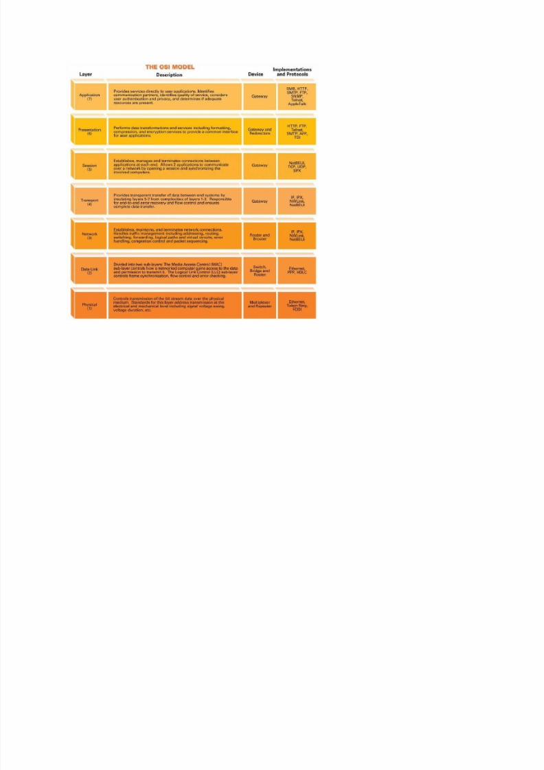
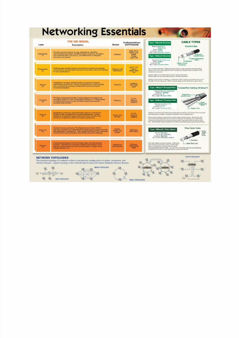
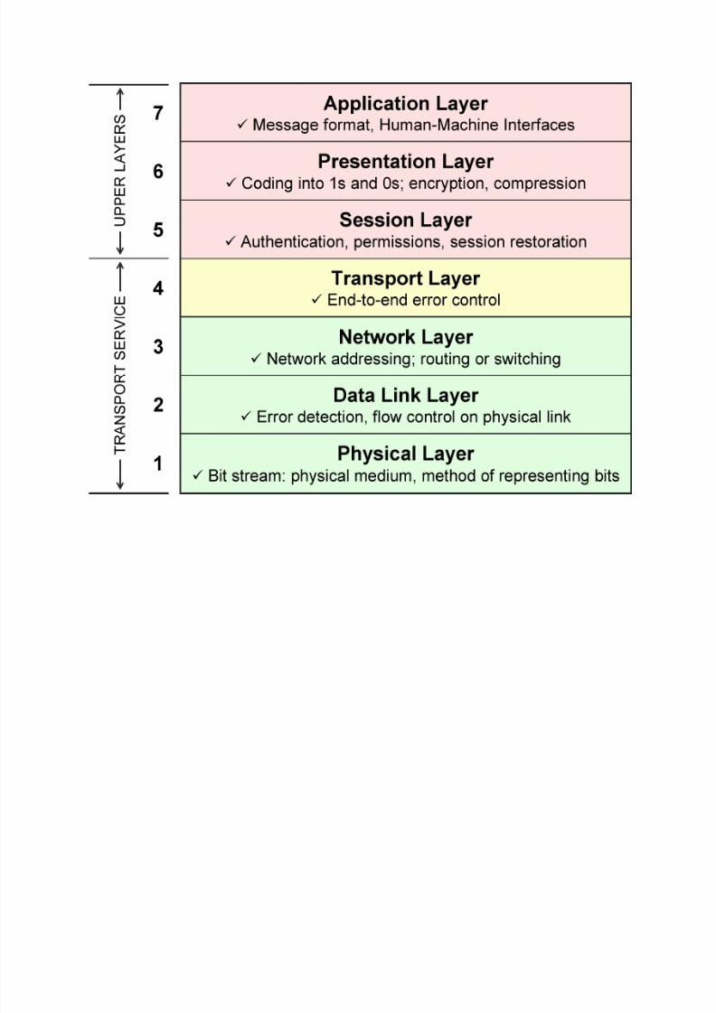
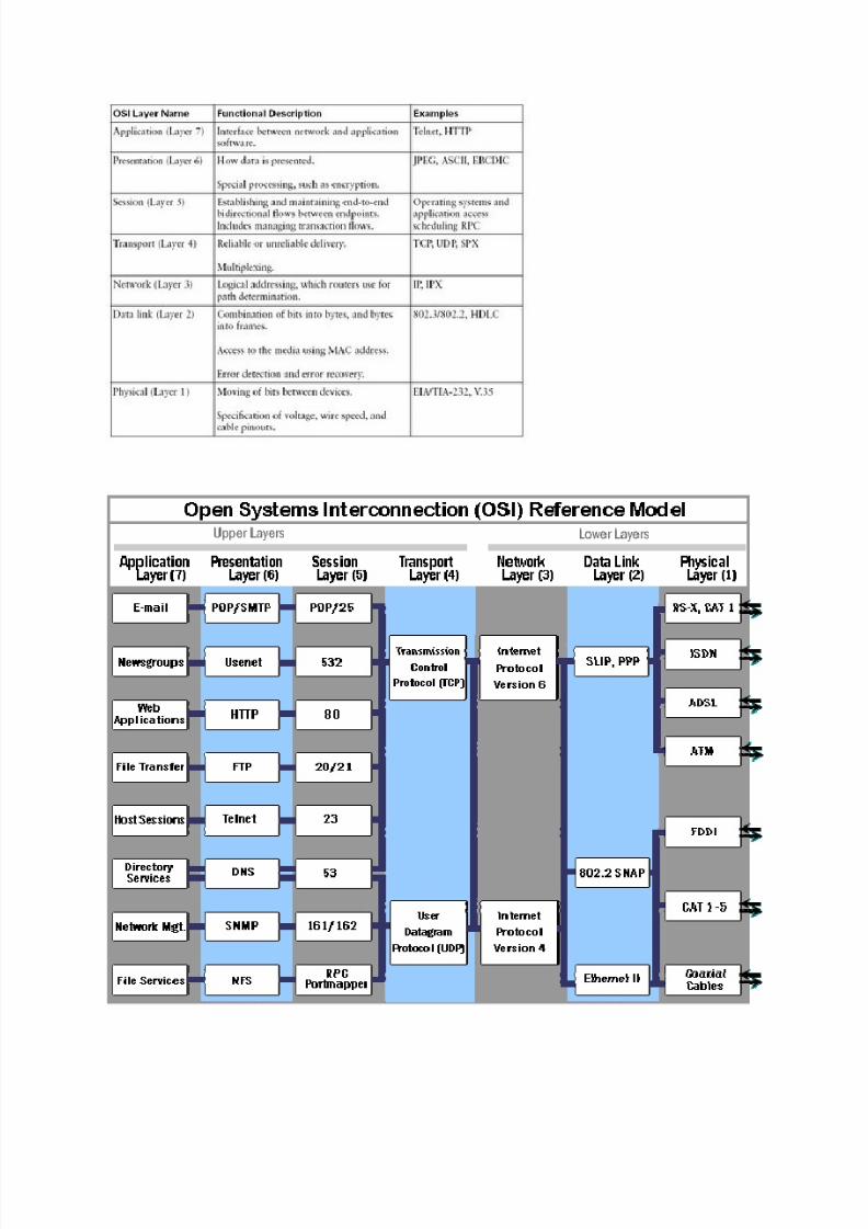
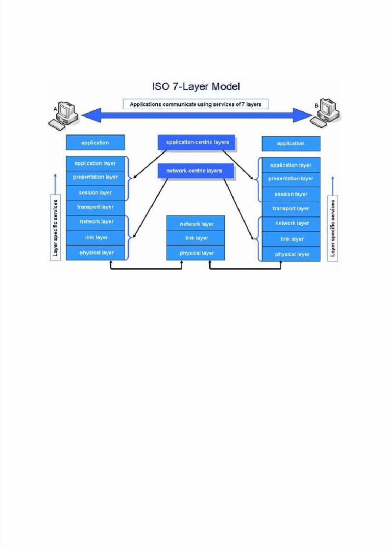
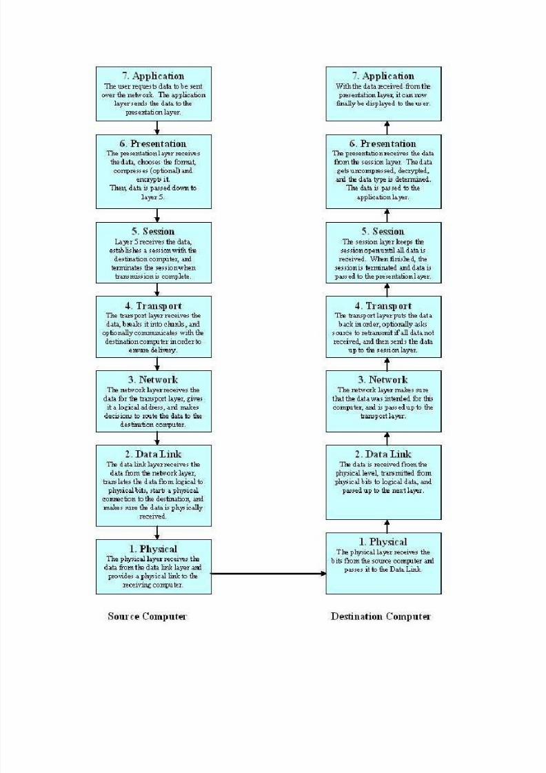
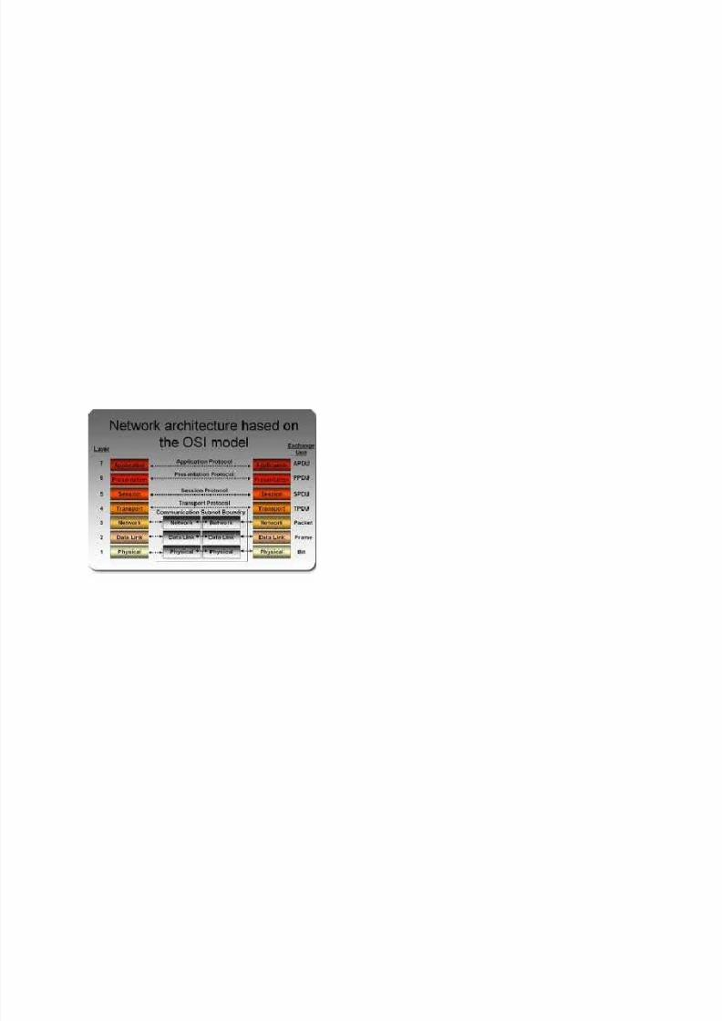
The ISO OSI model are explained below. The seven layers of the OSI model are:
y Applicationy Presentationy Sessiony Transporty Networky Antiqua">Data Linky Physical
1 Application layer:
This layer provides a means for the user to access information on the network through anapplication. Many user applications that need to communicate over the network interactwith the Application layer protocol directly. The user applications are not part of OSI
Application layer, use the networking services offered by the networking protocol suite.Application layer functions typically include identifying communication partners, anddetermining availability of required resources. Some examples of application layerimplementations include Telnet, File Transfer Protocol (FTP), and Simple Mail TransferProtocol (SMTP).
2 Presentation layer:
Presentation layer converts local host computer data representations into a standardnetwork format for transmission on the network. On the receiving side, it changes thenetwork format into the appropriate host computer's format so that data can be utilizedindependent of the host computer. ASCII and EBCDIC conversions, cryptography, and the
like are handled here.Examples of Presentation layer coding and conversion schemes include common datarepresentation formats, conversion of character representation formats, common datacompression schemes, and common data encryption schemes.
Presentation layer implementations are not typically associated with a particular protocolstack. Some well-known standards for video include QuickTime and Motion Picture ExpertsGroup (MPEG). QuickTime is an Apple Computer specification for video and audio, and MPEGis a standard for video compression and coding.
3. Session layer:
The session layer establishes, manages, and terminates communication sessions.Communication sessions consist of service requests and service responses that occurbetween applications located in different network devices. These requests and responses arecoordinated by protocols implemented at the session layer. Some examples of session-layerimplementations include AppleTalk's Zone Information Protocol (ZIP), and Decent PhaseSession Control Protocol (SCP).
4.Transport layer:
8/8/2019 Iso Osi Images
http://slidepdf.com/reader/full/iso-osi-images 2/17
Transport layer is responsible for providing reliable service between the hosts. Upper layerdatagrams are broken down into manageable datagrams and then appropriate headerinformation (such as sequence number, port number, etc.) is added to the datagram beforepassing it on to the Network layer. Two frequently used transport protocols are the TCP (Transmission Control Protocol) and the UDP (User Datagram Protocol).
Important features of Transport layer:
y Transport layer ensures reliable service.y Breaks the message (from sessions layer) into smaller datagrams, and appends
appropriate unit header information.y R esponsible for communicating with the Session layer
Important features of TCP/UDP:
y TCP/IP widely used protocol for Transport /Network layersy TCP: (Transport Control Protocol) TCP ensures that a packet has reached its intended
destination by using an acknowledgement. If not, it retransmits the lost messages.Hence, TCP is called a connection oriented protocol.
y UDP (Universal Data gram Protocol): UDP simply transmits packets over the internet.It does not wait for an acknowledgement. It is the responsibility of upper layerprotocols to ensure that the information had reached the intended partner(s). Hence,UDP is often called connectionless protocol.
y Application programs that do not need connection-oriented protocol generally useUDP.
5. Network layer:
Network layer is responsible for the routing of packets through the entire network. The layeruses logical addressing for this purpose. Note that the physical address (like MAC address) keeps changing from hop to hop when a packet travels from source to destination. As aresult, an address that doesn't change is required to ensure continuity between hops. This isnothing but logical address. For IP networks, IP address is the logical address; and forNovell network, IPX address is the logical address, and so on. This layer also provides forcongestion control, and accounting information for the network. IP (Internet Protocol) is anexample of a network layer protocol.
6. Data link layer:
Data link layer provides delivery of information frames between communicating partners.This layer is responsible for flow regulation, error detection and correction, and framing of bits for transmission. The network data frame is made up of checksum, source address,destination address, and the data itself. The largest frame size that can be sent is known asthe maximum transmission Unit (MTU).
Important features of Data link layer:
8/8/2019 Iso Osi Images
http://slidepdf.com/reader/full/iso-osi-images 3/17
y Assembles bits into frames, making them ready for transmission over the network.
y Provides error detection, and correction to transmitted frames. If the checksum isnot correct, it asks for retransmission. (Send a control message).
y Consists of two sub layers:1. Logical Link Control (LLC): Defines how data is transferred over the cable and
provides data link service to the higher layers.2. Medium Access Control (MAC): Controls media access by regulating the
communicating nodes using pre-defined set of rules. (i.e. Token passing,Ethernet [CSMA/CD] all have MAC sub-layer protocol).
Different Data link layer protocols define different network and protocol characteristics,including physical addressing, network topology, error notification, sequencing of frames,and flow control. Physical addressing (as opposed to logical addressing) defines how devicesare addressed at the data link layer. The protocols used in Data link layer are SLIP, PPP,and CSLP.
7. Physical layer:
This is the bottom-most layer of the OSI model. The Physical layer handles the bit-levelcommunications across the physical medium. The physical medium could be made up of
wired electrical signals, or light, or radio (wireless) signals. Physical layer specificationsdefine characteristics such as media, data rates, maximum transmission distances, andphysical connectors.
Some of the important standards that deal with physical layer specifications are:
R S-232(for serial communication lines), X.21, EIA 232, and G730.
Physical layer and Data link layer implementations can be categorized as either LAN or WAN specifications.
Vijayanand has done his post graduation (M.E.) in Communication Systems. He has several
years of experience in electronic assembly and design, rf testing, and networking. He is aCisco Certified Networking Professional, and an MCSE (Microsoft Certified SystemsEngineer). He is a director of Anand Software and Training Pvt. Ltd. Complete tutorial onNetworking is available at SimulationExams.com
8/8/2019 Iso Osi Images
http://slidepdf.com/reader/full/iso-osi-images 4/17
8/8/2019 Iso Osi Images
http://slidepdf.com/reader/full/iso-osi-images 5/17
8/8/2019 Iso Osi Images
http://slidepdf.com/reader/full/iso-osi-images 6/17
8/8/2019 Iso Osi Images
http://slidepdf.com/reader/full/iso-osi-images 7/17
8/8/2019 Iso Osi Images
http://slidepdf.com/reader/full/iso-osi-images 8/17
8/8/2019 Iso Osi Images
http://slidepdf.com/reader/full/iso-osi-images 9/17
8/8/2019 Iso Osi Images
http://slidepdf.com/reader/full/iso-osi-images 10/17
8/8/2019 Iso Osi Images
http://slidepdf.com/reader/full/iso-osi-images 11/17
http://technet.microsoft.com/en-us/library/cc786900(WS.10).aspx
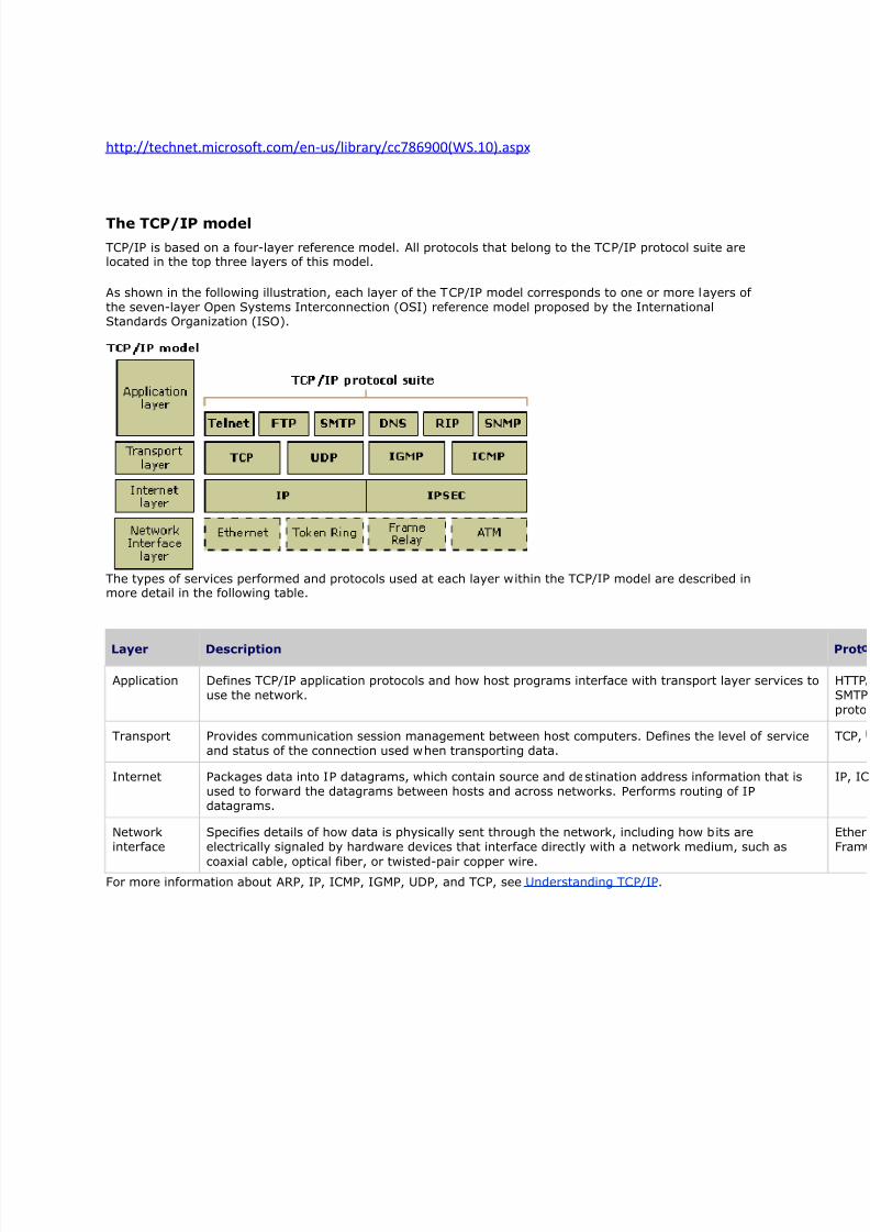
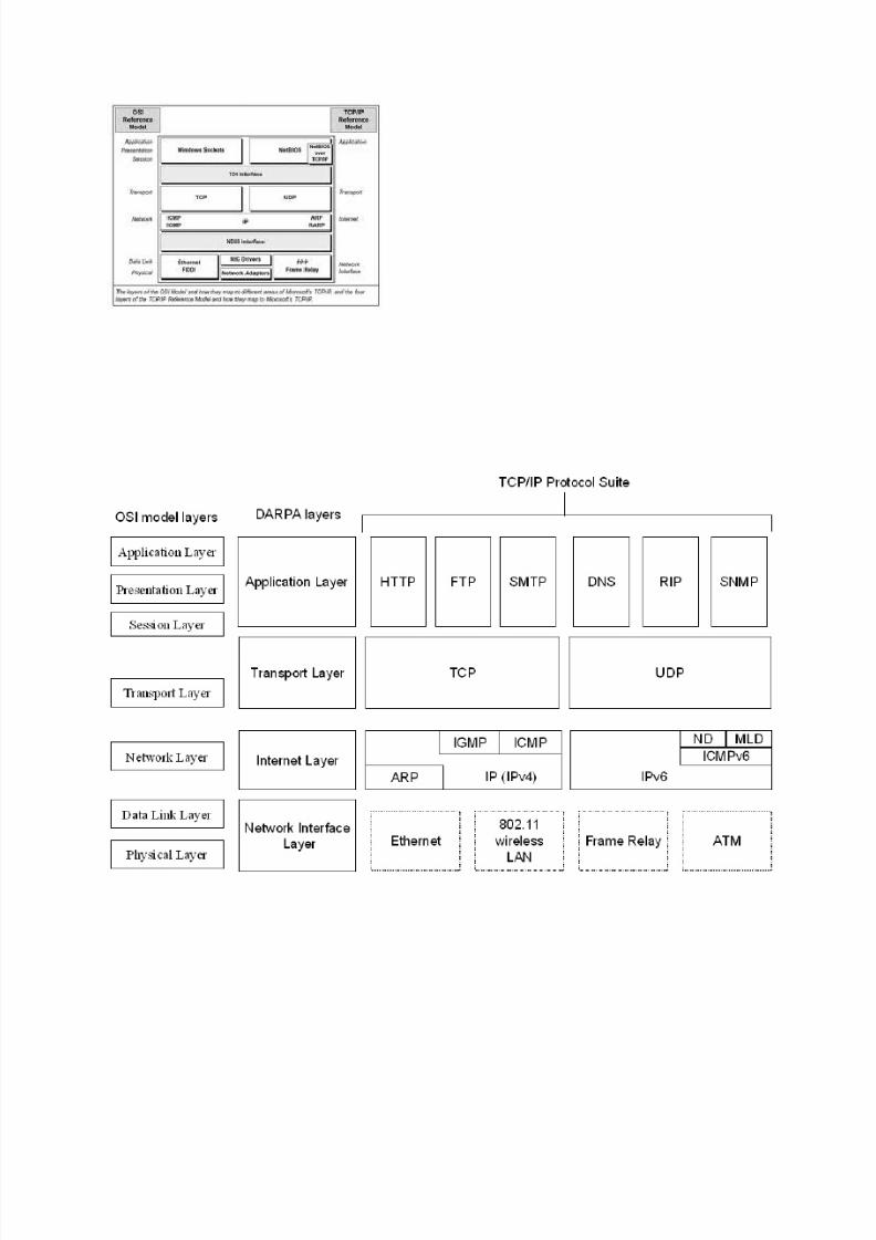
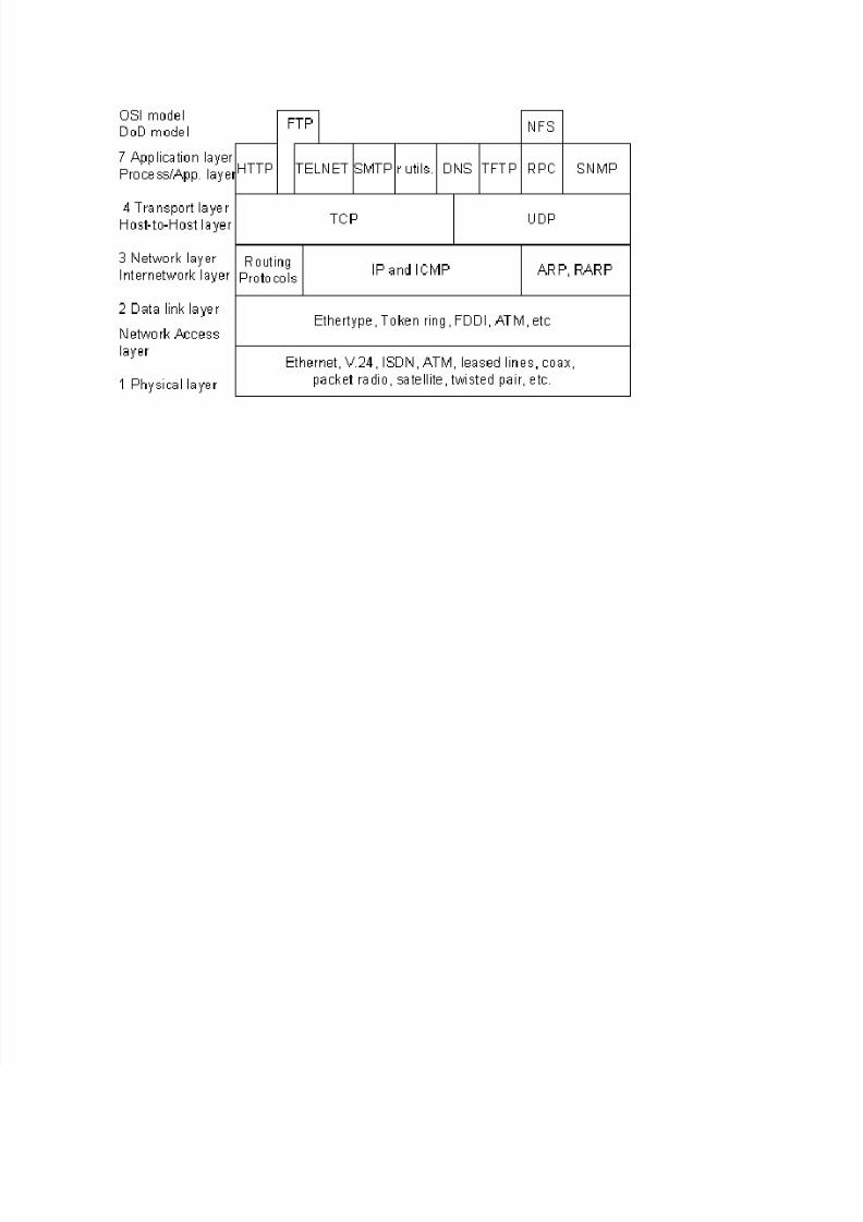
The TCP/IP model
TCP/IP is based on a four-layer reference model. All protocols that belong to the TCP/IP protocol suite arelocated in the top three layers of this model.
As shown in the following illustration, each layer of the TCP/IP model corresponds to one or more layers of the seven-layer Open Systems Interconnection (OSI) reference model proposed by the InternationalStandards Organization (ISO).
The types of services performed and protocols used at each layer within the TCP/IP model are described inmore detail in the following table.
Layer Description
Application Defines TCP/IP application protocols and how host programs interface with transport layer services tuse the network.
Transport Provides communication session management between host computers. Defines the level of serviceand status of the connection used when transporting data.
Internet Packages data into IP datagrams, which contain source and destination address information that isused to forward the datagrams between hosts and across networks. Performs routing of IP datagrams.
Networkinterface
Specifies details of how data is physically sent through the network, including how bits areelectrically signaled by hardware devices that interface directly with a network medium, such as
coaxial cable, optical fiber, or twisted-pair copper wire.
For more information about AR P, IP, ICMP, IGMP, UDP, and TCP, see Understanding TCP/IP.
8/8/2019 Iso Osi Images
http://slidepdf.com/reader/full/iso-osi-images 12/17
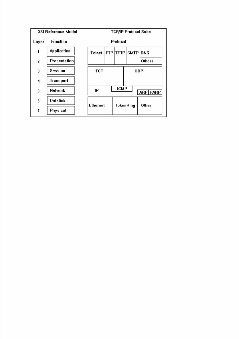
http://www.buzzle.com/articles/tcpip-model-vs-osi-model.html
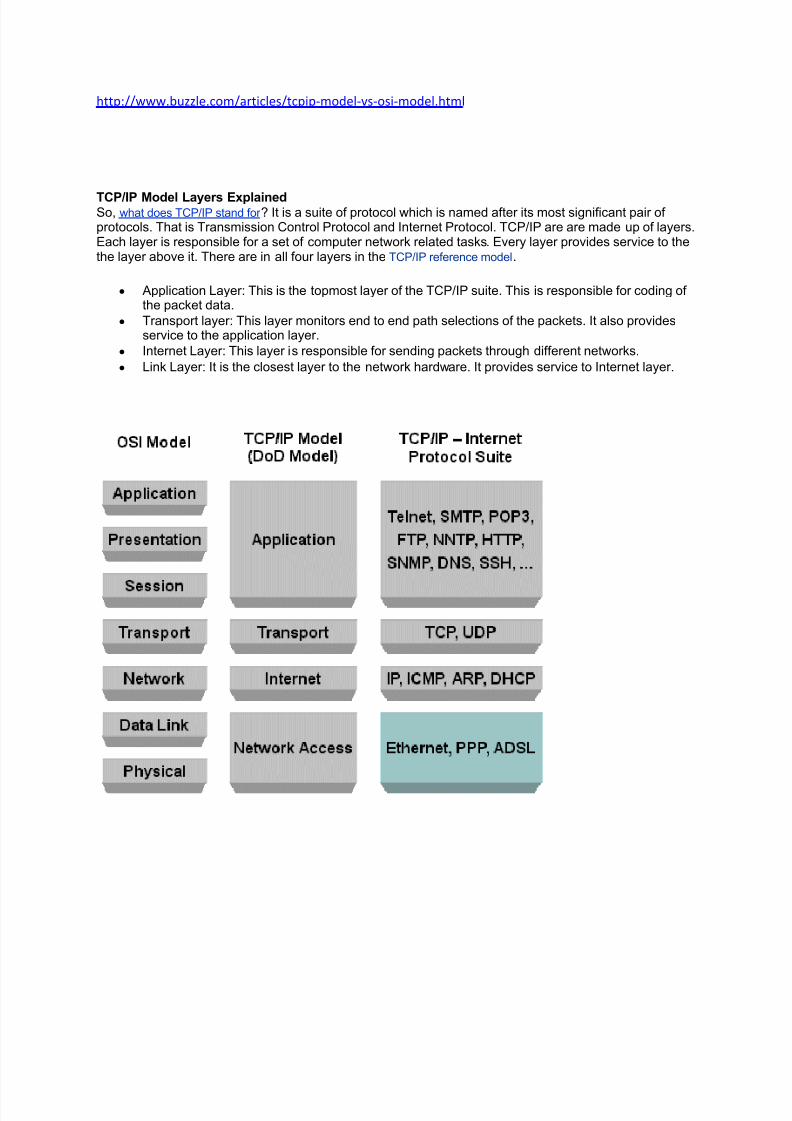
TCP/IP Model Layers Explained So, what does TCP/IP stand for ? It is a suite of protocol which is named after its most significant pair of protocols. That is Transmission Control Protocol and Internet Protocol. TCP/IP are are made up of layers.Each layer is responsible for a set of computer network related tasks. Every layer provides service to thethe layer above it. There are in all four layers in theTCP/IP reference model.
y Application Layer: This is the topmost layer of the TCP/IP suite. This is responsible for coding of the packet data.
y Transport layer: This layer monitors end to end path selections of the packets. It also providesservice to the application layer.
y Internet Layer: This layer is responsible for sending packets through different networks.
y Link Layer: It is the closest layer to the network hardware. It provides service to Internet layer.
8/8/2019 Iso Osi Images
http://slidepdf.com/reader/full/iso-osi-images 13/17
8/8/2019 Iso Osi Images
http://slidepdf.com/reader/full/iso-osi-images 14/17
8/8/2019 Iso Osi Images
http://slidepdf.com/reader/full/iso-osi-images 15/17
8/8/2019 Iso Osi Images
http://slidepdf.com/reader/full/iso-osi-images 16/17
8/8/2019 Iso Osi Images
http://slidepdf.com/reader/full/iso-osi-images 17/17