issue 0 -no'l/ember, 2006 - artc - extranet · strail rubber crossings are 2440mm wide and...
TRANSCRIPT


ISSUE 0 -No'l/ember, 2006
ContentsContents 1
1.1 Product Specification and Requirements 21.1.1 Differential Settlement and "T" Beams 3
1.2 Training 31.3 Installatiorl Guide 3
1.3.1 Site Preparation 31.3.2 Tools, Materials and Packaging 41.3.3 Inner Panel Installation 41.3.4 Outer Panel Installation 41.3.5 Six Foot Panel Installation 51.3.6 Removal of Crossing for Maintenance 51.3.7 Reinst:allation 5
1.4 Product Geometry Tolerances 61.5 TGSI Tiles 8
1.5.1 Description 81.5.2 Supplier 81.5.3 Spares 81.5.4 Mainb~nance 81.5.5 Previous Installations of TGSI Tiles 8
1.6 Installation of TGSI Tile~ 91.6.1 Tools and Equipment Needed 91.6.2 Method 91.6.3 Warr21nty 10
1.7 Drawing Index 111.7.1 Typical Layout Drawing of Pedestrian Crossing 111.7.2 Details of Layout of Six Foot Panels 121.7.3 Details of Edge Beam Interface with Outer Panels 131.7.4 Details of Ramped Outer Panels 14
1.8 Quality Certificates 151.8.1 Occupational Health, Safety and Environment 16
1.9 Maintenanlce, Spares and Repairs 171.9.1 Maintenance 171.9.2 Spares 171.9.3 Repairs 17
1.10 Technical Support 181.10.1 Austri31ia 181.10.1 Germany 18
1.11 Supplier and Manufacturer 18

Strail rubber crossings are 2440mm wide and consist of the modular panels, 2 x900mm and 1 x 640mm. The panels are locked together with tie rods that provide auniform flat surface. The inner panels are designed to fit between the rails. Theflangeway is fully dosed as the panel extends under the head of the rail. The surfacehas been designed as non-slip.
The outer panel:; are cut to 1375mm and have been designed to be offset 125mmfrom the crib post (1500mm from rail) in accordance with the Victoria PedestrianCrossing standard guidelines. In addition to this, the six foot contains at 'least twopanels sections (up to three) that completely fill the six foot to achieve a continuousrubber surface from gate to gate.
To support the ~;ix-foot panels over this long span rather than relying on the ballast toprovide a uniform level, a slit is cut in the six-foot panels and a steel plate is insertedto maintain the panel levels at the joint. The steel plates are required have a firm base,such as compacted crushed rock, asphalt or concrete underneath them.
Welds or insulat:ed joints cannot be accommodated where the rubber panels are beingused. Sleeper spacings are to be between 600mm (min) and 610mm. This is to ensurethat the panels and that movement stoppers can be installed to stop an'y' longitudinalmovement of thle crossing. As the panels are placed perpendicular to the: rail, skewcrossings must be accommodated by increasing the overall width of the crossing andplacing the line of TGSI tiles between the posts accordingly to maintain a 1800mmwalkway. Some curvature in the rail can be catered for with the panels at the crossing.
Crossing sites are to be cleaned of existing crossing materials prior to installation. Allasphalt is to be cleaned from the rails, clips and sleepers. Ballast is to bE~ no higherthan the top of the sleepers. All timber sleepers are to be uniform and IE~vel with eachother with no irregular pieces that could jeopardise the level of the panels.
Approaches to 1:he crossing are to be brought to the level of the track as to allow theouter panels to be placed level to the track. A steel edge beam is integrcll to the outerpanel. Its function is to support the panel rather than relying on the ballast forcomplete support, it acts as an interface between the asphalt approach ,and rubbersurface allowin~~ for easy removal and maintenance of the crossing without the need todisturb the asphalt.

1.1.1 Differential Settlement and "T" Beams
Differential settlement may occur between panels in fully rubberised crossings if thereis insufficient support or varying foundation at the crossings. Installing "-r" beamsunder the outer edges of the outer panels at the time of installation can reduce theincidence/risk of differential settlement.
However, it must be noted that Strail is only a supplier of rubber panels clnd suppliesdetails of the T 13eams to ensure satisfactory support of the panels. Formation andcompaction undl:r the T Beams must be determined by the client in accolrdance withthe client's ballast formation and track specifications.
Strail Australia ~lrovides instructions for general product installation, removal andmaintenance in~;tructions. Strail also provides on site support and training during theinstallation of initial crossings.
1.3 Installation Guide
1.3.1 Site Preparation
Track assembly can be concrete or wooden sleepers according to agreed layout
specification.Check that all sleeper plates, screws and clips are correctly assembled before installingStrail rubber crossing.Complete geometry checklist on rail and rubber crossing panels.Ballast profile must be below the top of the sleeper as not to interfere with the
panels.Ballast must be clear of all other components such as sleeper pads, rail f'oot so that theInner Panels (Type 'A') and Outer Panels (Type 'B') can be installed. .
Avoid installation where insulated joints (IRJ) and welds are within the crossing panel
system.
Crib alignment "to be in accordance with Victorian Rail Industry Operators GroupStandards criteria for Infrastructure at Railway Level Crossings.Sleeper spacin£1 to be between 600 and 610mm centres. Ideally the cen"treline of thecrossing is to ble inline with the centreline of the first two sleepers space:d at 300mm.A minimum number of sleepers are required to support the panels4 sleepers are required to support a 1800mm level crossing.S sleepers are required to support a 2440mm level crossing.
-
~ ]J~~~~~~~ ' i .. !
iiIS . A I,
P [traJf ustraJa 'tv LtcNew Equipment and ~;ystemApproval -pedeStrailAustralian f~ail Track Gbrpor~tion

1.3.2 Tools, Materials and Packaging
Ballast fork, pelic:an pick, broom, lifting hand trolley, sledge hammer, cro\Nbar and setof ratchet spannersAssembly tool for standard gauge and Velo-Strail panels (single piece)Safety goggles, ,~Ioves and dust masks (if cutting panels)Cutting can be carried out using a sharp knife, sabre saw, chain saw, circular saw (fortop surface cutting to give a clean edge) and/or hammer and chisel. An e:lectric planeror router may also be used to remove a thin layer of rubber from the under-surface ofthe panels if nec:essary.Rubber panels ~,ill be packed on pallets including a packing slip with parts listing andinstallation diagram.Lifting of panels requires a minimum of 4 persons when moving short distances, or useof a hand trollev', backhoe or other suitable mechanical device is preferred whenmoving the panels long distances.
1.3.3 Inner Panel Installation
Ensure sleepers are clean.Place deflection plate towards the direction of train traffic. Note the tongue or groovesticker to match to the panels.Start by placing in the panels lA and 18 together.
Continue and pl,ace panels 2A, 2B 3A and 3B together matching the tongue and groovewith panels 1A and lB.
Use a sledge hammer to knock together the panels into place so they loc:k together.
Place deflection plate and end plate and lift into place and pass the tie rod through theholes within the crossing panels.Fit movement s1topper to sleeper and adjust the movement stopper such that it is hardup against the ~iide of the end panelTighten the rod:) firmly and do not over-tighten!
1.3.4 Outer PanE!llnstallation
Ensure sleepers are clean.
Position the B panel in the same alignment as the inner panels.Use a sledge hammer to close the gaps and repeat with the remaining tie rodsPlace edge beam behind the panels and ensure that the panels are tightly fitting thehead of the rail,Fit movement stopper to sleeper and adjust the movement stopper such that it is hardup against the ~;ide of the end panel.
l~m]J
Strail Au~traliaf:ty Ltc~ : New Equipment and ~)ystem Approva1 -Pede Strall
Australian Rail Track Corporatioq
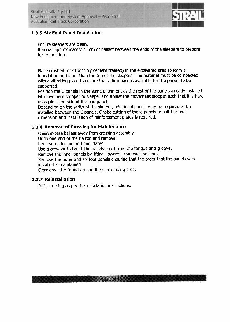
1.3.5 Six Foot Palnel Installation
Ensure sleepers are clean.Remove approxilmately 75mm of ballast between the ends of the sleeper!; to prepare
for foundation.
Place crushed rack (possibly cement treated) in the excavated area to form afoundation no higher than the top of the sleepers. The material must be ,::ompactedwith a vibrating plate to ensure that a firm base is avail(~ble for the panels to be
supported.Position the C p(~nels in the same alignment as the rest of the panels alre:ady installed.Fit movement stopper to sleeper and adjust the movem,ent stopper such that it is hardup against the s'ide of the end panelDepending on the width of the six foot, additional panels may be requirelj to beinstalled between the C panels. Onsite cutting of these panels to suit the finaldimension and installation of reinforcement plates is required.
1.3.6 Removal of' Crossing for Maintenance
Clean excess ball last away from crossing assembly.Undo one end o'F the tie rod and remove.Remove defiecti'Dn and end platesUse a crowbar u) break the panels apart from the tongue and groove.Remove the inner panels by lifting upwards from each section.Remove the outer and six foot panels ensuring that the order that the panels were
installed is maintained.Clear any litter found around the surrounding area.
1.3.7 ReinstallatiionRefit crossing a~; per the installation instructions.
r:,]~~~
~
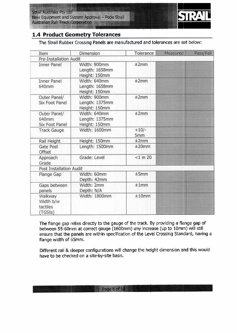
1.4 Product GE!Ometry TolerancesThe Strail Rubbe:r Crossing Panels are manufactured and tolerances are set below:
The flange gap relies directly to the gauge of the track. By providing a flclnge gap ofbetween 55-60mm at correct gauge (1600mm) any increase (up to lOmrn) will stillensure that the panels are within specification of the Level Crossing Standard, having a
flange width of 155mm.
Different rail & ~;Ieeper configurations will change the height dimension and this would
have to be checked on a site-by-site basis.
Gaps between p,anels are governed by the tension in the tie rods. The ro(js are to befirmly tightened but not over-tightened as the panels will buckle and warp.
The grade of thE~ outer or six foot panels is desirable to be level. If, however, thecircumstances rE~quire a grade, for example height difference between two tracks andthe approaches, then a grade no greater than 1 in 20 is permitted. Where the grade isnegative (eg. Sloping down towards the rail, wedge packers will be place,d underneaththe panels to bridge the gap between the sleeper and panel to reduce thl~ flexing.
1.5 TGSI Tiles
1.5.1 [-escription
Tiles are manufactured from recyclable UV stabilised Hi~lh Density Polyethylene (HOPE)plastic with the (jimensions adopted from AS1428.4.
The raised buttons are made from UV stabilised thermo plastic polyurethane, providinga good slip and j~brasion resistant surface. Both tiles an(j buttons are coloured 'SafetyYellow' and the materials from which they are manufactured are considered to havegood durability. The tiles are held in place in the rubber with stainless stE~el Fischerfasteners (Part ~Jo. 50372)
1.5.2 Supplier
The proposed T<:;SI tiles will be supplied by:
Phoenix AG (Au~itralia) Pty Ltd26 Mockridge St"Wantirna South Vic 3152Telephone: (03) 9800 3360
1.5.3 Spares
It is recommended that PN hold 100 sets (tiles, buttons and fasteners).
1.5.4 Maintenanc:e
No regular on-going maintenance is envisaged. However, any tiles or buttons that aredamaged are easily replaced.
1.5.5 Previous Installations of TGSI Tiles
Tiles of the above description are a new product. Howe'/er, installations of similar tileshave been carried out at:Glenferrie Rd., K:ooyongBlackwood St" CarnegieSmith St" Thornlbury
In the future it is planned that the tiles be installed at the upcoming Pedestrian Gate
update program.
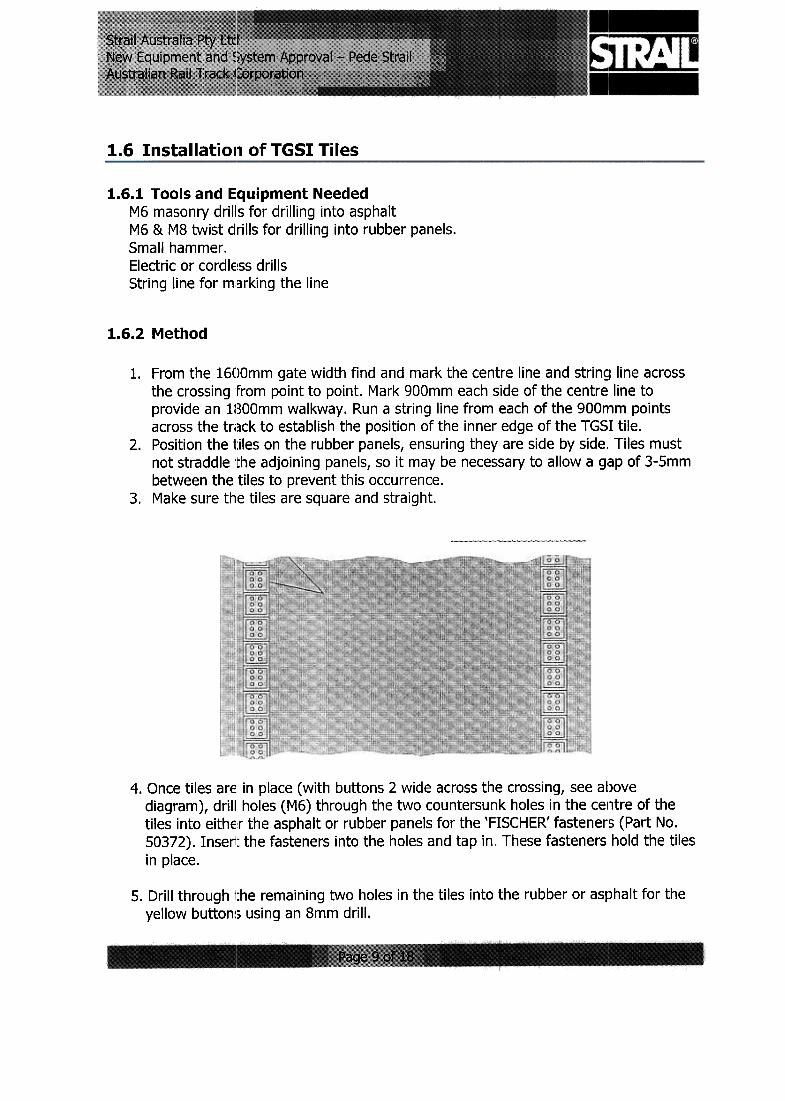
1.6 Installation of TGSI Tiles
1.6.1 Tools and Equipment NeededM6 masonry drills for drilling into asphaltM6 & M8 twist drills for drilling into rubber panels.Small hammer.Electric or cordlE~ss drillsString line for m,arking the line
1.6.2 r-'ethod
1. From the 1600mm gate width find and mark the centre line and strin~lline acrossthe crossing from point to point. Mark 900mm each side of the centre line toprovide an 1800mm walkway. Run a string line from each of the 900n!1m pointsacross the track to establish the position of the inner edge of the TGSI tile.
2. Position the t:iles on the rubber panels, ensuring they are side by side.. Tiles mustnot straddle Ithe adjoining panels, so it may be nece~;sary to allow a gap of 3-Smmbetween the tiles to prevent this occurrence.
3. Make sure the tiles are square and straight.
4. Once tiles are in place (with buttons 2 wide across the crossing, see abovediagram), drill holes (M6) through the two countersurlk holes in the centre of thetiles into eithe:r the asphalt or rubber panels for the 'FISCHER' fasteners (Part No.50372). Insent the fasteners into the holes and tap in" These fasteners hold the tiles
in place.
5. Drill through jche remaining two holes in the tiles into the rubber or asphalt for theyellow button~; using an 8mm drill.

Insert the two buttons into the tiles and tap into place so the base of the button islevel with the upper surface of the tile.
There are approx. 88-90 tiles to be installed at each crossing with two tracks andone walkway. Installation for such a crossing takes about one hour with 3 persons
1.6.3 Warranty
No TGSI returns will be accepted for reasons other than defects in manufacturingworkmanship or material. Damage caused by others by any cause beyond the controlof Phoenix AG (J\ustralia) Pty Ltd, including but not limited to damage caused bymisuse, abuse, i3ccident, mishandling, vehicular traffic, fire, storm, or othler acts ofnature is not considered defects in material or workmanship.
This warranty does not apply to conditions caused by normal wear and tear upon theproduct. Phoeni:( AG (Australia) Pty Ltd shall repair or replace, at its option,warrantable deflective product or part and will return the shipment at no cost to thecustomer.

1.7 Drawing Index
1.7.1 Typical LaYIQut Drawing of Pedestrian Crossin~1

1.7.2 Details of Layout of Six Foot Panels
CRUSHEDRnrK
- tf c, "
1-
E ~,,~
'-'SA A .:)
I~~~~
I 1.1
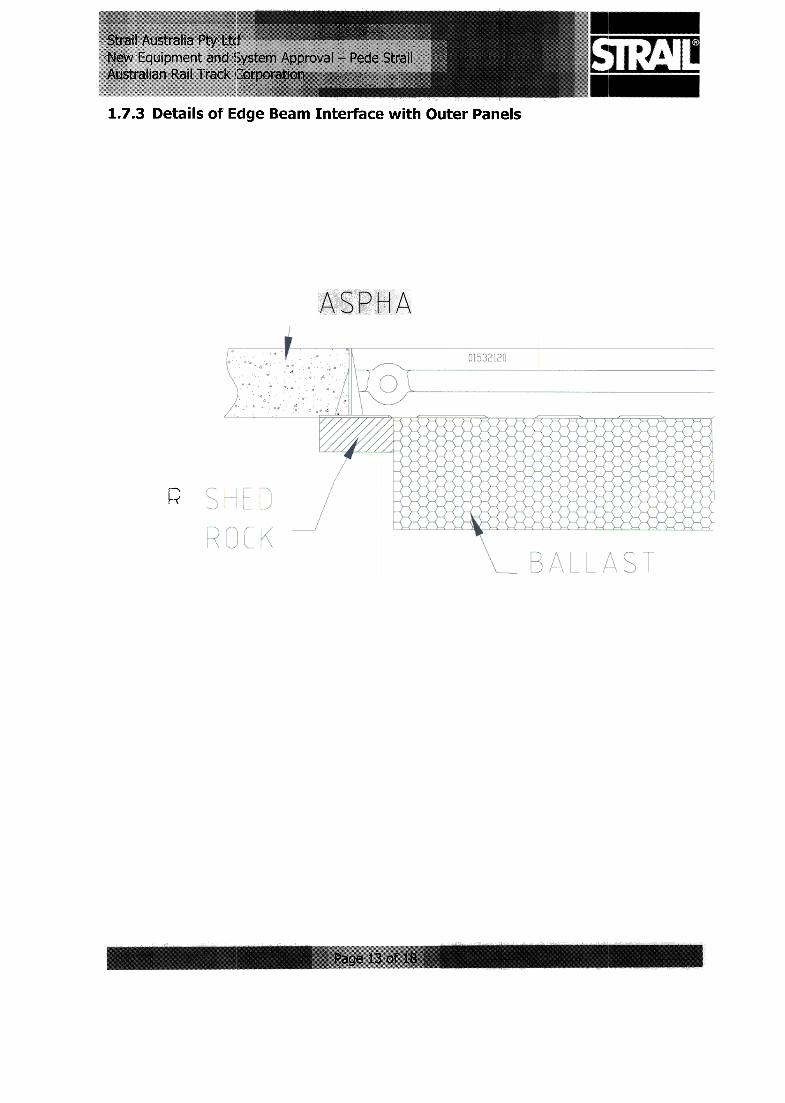
1.7.3 Details of Edge Beam Interface with Outer Panels
R

1.7.4 Details of Ramped Outer Panels
~!
WEDGE
PACKER
Ramped Down Outer Panel -PVC packer required to fill gap
')
Ramped Up Oub~r Panel -Rebate sleeper to fit panel
1.8 Qualiq~~ificates

THE INTERNATIONAL. CERTIFICATION NETWORK
CERTIFICiiTEIONet and COS
hereby certify that the organization
has implemented and maintains a
Quality Management Sy.stem
which fulfills the requirements of the following standard
ISO 9001 : 2000
Issued on:Validity date:OQS certified since:Registration Number:
2006-07-04
2009-03,-22
1994-0~~-25
AT -001 ~19/0
Dr. Fabio Roversi
Presid~nt of IQNet..--, I' "Net *""
,~~~"='IQNet Partners.:
AENOR Spain AFAQ AFNOR F1T1noo AlB-Vin~tte International Belgium ANCE Mexico APCER Portugal CISQ Italy CQC China CQM China
CQS Czech Republic Cro Cert Croatia OQS Germany OS Denmark ELOT Greeoo FCAV Brazil
FONOONORMA Venezuela HKQAA China ICONTEC Colombia IMNC Mexico lRAM Argentina JQA Japan KFQ Korea
MSZT Hungary Nemko AS Norway NSAI Ireland PCBC Poland PSB Certification Singapore QMI Canada Quality Austria Austria
RR Russia SAI G)()bal Austmlia Inspecta Certification Finland SJI Ismel SIQ Slovenia SQS Switzerland SRAC Romania
TEST St Petersburg Russia YUQS Serbia and MontenegroIQNet is represented in the USA by: AFAQ AFNOR, AlB-Vin~tte International, C[SQ, DQS, NSAI, QM[ and SAI Global
.The list of [QNet partn"rs is valid at the time of issue of this certificate. Updated information is available under www.iqnet-certification.com
0-84529 Tittmoning, GollstraBe 8Scope of application: STRAIL systems for track surfaces
NACE: 25.0.0 EAC: 14


1.8.1 Occupational Health, Safety and Environment

Strail Australia Flty Ltd
Our responsibilitv' is onE~ of reconciling human expectations, environmental concerns andcorporate interes;ts. W4~ observe the applicable laws within Australia.
We design our products and processes with an emphasis on avoiding any negativeconsequences for the environment.
IJ
We conserve r~~sources by reducing the consumption of energy, water, raw materialsand processin~~ materials.
Q
We enact comprehensive safety standards0
We conduct operational emergency training to avoid injury to persons, property andthe environment.
[J
We train, inforrn and motivate our employeesa
We include our contract partners, suppliers and customers in our activities.Q
We communicate openly with our customers and suppliers regarding planning andactivities.
(]
We constantly monitor OHS&E activities and strive for ongoing improvemE~ntQ
All our employees and all persons working on behalf of our company are obliged to
follow these OHS&E standards and to actively participate.
P.M. Roseman -Director A. J. Roseman -DirectorRoseman-Director

1.9 Maintenanlce, Spares and Repairs-
1.9.1 Maintenanc:e
It is recommended that ARTC incorporate pedestrian crossing inspection as part of itsregular maintenance procedure. Inspection should include movement of panels,tightness of tie rods, location of the crossing within the track and condition of the TGSItiles.
1.9.2 Spares
Tie rods, end plates, deflection plates and movement stoppers can be procured directlyfrom the factory within 2 weeks. However, it is recomml~nded that ARTC hold thefollowing quanti1:ies in stock:
Tie Rods for 2440 crossings x 8Deflection plates; for broad gauge x 2Deflection plates; for standard gauge x 2Movement stop(:lers x 2
Because of the diverse range of rail/sleeper/clip combinc3tions within the :;ystem, ARTCwould need to ci3rry a wide range of spare panels. Therefore, it is suggested thatrather than carr)ring a large inventory of different panels it may be more economic toairfreight any emergency panels required, direct from the manufacturer in Germany.However, the finial decision is with ARTC.
Lead time for spare panels is 8-10 weeks via seafreight and 2-3 weeks by airfreight.
Spare parts should be ordered through Strail Australia Pt), Ltd.
1.9.3 Repairs
Panel damage nl~eds to be assessed before it is determined whether rep21irs can beexecuted.
Repairs, if necessary, can be carried our by:
Strail Australia Pty Ltd,orGummiwerk Kraiburg GmbHGollstrasse 8,0-84529 Tittmoning,Germany

1.10.1 Australia
Technical SUPPOlt in Australia is provided by:
Strail Australia Pty Ltd.,26 Mockridge St"Wantirna South Vic 3152Contact: Jeff Ro~;emanTelephone: (03) 9800 3360
1.10.1 Germany
Technical SUPPOlt from Germany is available from:
Gummiwerk Kraiburg GmbHGollstrasse 8,0-84529 Tittmoning,
GermanyContact: Robert Kaser
Pede Strail crossings are supplied in Australia by:
Strail Australia Pty Ltd26 Mockridge St..,Wantirna South Vic 3152Telephone: (03) 9800 3360
Pede Strail crossings are manufactured by:
Gummiwerk Kraiburg GmbH,Gollstrasse 8,0-84529 TittmoningGermany