rout & return - aluminum composite panels |sign panels
TRANSCRIPT

rout & returnINSTALLATION GUIDE
tech Support : 800.523 .2347 LaminatorsInc.com
Effect ive October 2016

TABLE OF CONTENTS
Handling and Maintenance of Omega-Lite® Panels 1
System Limitations and Pre-Installation Requirements 2
Panel Assembly: General Fabrication 3-4
Panel Assembly: Corners and Soffit Transitions 5-6
Typical Wall Layout and Stiffening Requirements 7
System Installation 8
Essential Equipment and Materials 9
Denotes Additional Required Downloadable Content
SyStem Overview
The Rout & Return installation system from Laminators Inc. is a classic ACM veneer system designed for installation with Omega-Lite® panels. Variation in joint options and panel colors creates a multitude of sophisticated, modern aesthetics. While traditionally shop-fabricated, the efficient design of the Rout & Return system makes field fabrication possible, leading to even more flexibility during installation. This installation system complies with the requirements of the NFPA 285 standard for multi-story fire testing.
warranty DiSclaimer
Failure to follow ANY of the guidelines contained within this document or those referenced at LaminatorsInc.com will void your warranty. For Laminators Technical Support, call 800.523.2347.
electrOnic DOcumentS nOtice
Approved product listings, CAD details, and technical bulletins available at LaminatorsInc.com are to be considered a part of this installation manual and are REQUIRED to install this system properly. Contact Laminators Technical Support or visit LaminatorsInc.com to make sure you have the latest documents regarding this panel system before proceeding with installation.

1Tech Support: 800.523.2347
Material ReceivingUpon receipt of panels and system accessories, perform a visual inspection and inventory to identify any damages that may have occurred during shipping or any materials that may be missing. Any damages or missing materials must be noted on the bill of lading at the time of receipt and must be immediately reported to the distributor from which the product was purchased.
StoragePanels are to be stored horizontally on pallets in a dry, well-ventilated environment under the protection of a temporary or permanent roof structure. No more than 1,500 pounds of panels are to be stacked on one pallet. If panels are to be stored in an exterior area, they must be placed under a well-ventilated, waterproof covering. Storage temperatures are not to exceed 120°F. Panels should be stored in an area protected from other construction activities and associated debris. Other materials shall not be stacked or placed in contact with panels to prevent staining, denting, or other damages.
Laminators’ warranty does not cover damages to panels caused by improper storage. Storage conditions should be continuously monitored as any water infiltration, standing water, construction debris, or excessive temperatures will cause damage to the panels that will not be covered under warranty.
HandlingPanels are shipped with a protective masking to minimize scratching and staining during installation. Protective masking should be left on the field of the panel during installation to minimize potential damages from construction activities. Note that all masking must be removed within 2 weeks of panel installation, otherwise removal may become difficult and the masking adhesive may affect the appearance of the panel following removal.
Handle panels with clean work gloves to avoid hand injury from any sharp edges and to prevent staining of the prefinished panel surfaces. When moving individual panels from stacks, always lift one panel completely off the next to prevent surface scratches from construction debris. Do not slide one panel across another. Glazing suction cups are recommended to handle panels whenever possible.
CuttingPanels are shipped in standard sizes that can be cut to required installation size on the jobsite. To cut Omega-Lite® panels, use a circular saw or table saw with a sharp, carbide-tipped blade (40-tooth minimum). Do not remove the protective masking from the panel face prior to cutting. After cutting, use a deburring tool (available from Laminators) to remove burrs or sharp edges from the panels.
CleaningOmega-Lite® panels should be cleaned at regular maintenance intervals following procedures documented in AAMA 609 & 610-02 “Cleaning and Maintenance Guide for Architecturally Finished Aluminum.” During installation, mineral spirits can be used to remove uncured caulk and sealants. Never soak panels in solvents or allow solvents to be left in prolonged or continuous contact with panel surfaces as this can cause damages to panel finishes.
Scratches and Rub MarksTouch-up paints are available from Laminators. Contact Laminators Technical Support for additional information.
Metallic Paint and Anodized FinishesWhen installing panels with metallic and anodized finishes, it is very important that the directional arrows on the panel masking are oriented in the same direction. Color variation is a characteristic of aluminum composite panels with metallic paint and anodized finishes. Laminators DOES NOT warrant a color match for panels with metallic and anodized finishes.
To ensure good color uniformity in panels with metallic finishes, periodically check adjoining panels by partially removing masking as the installation progresses. The masking should be reapplied to the panel to protect it. Should any defects be found, stop work immediately and contact Laminators for assistance.
Panel Color Coordination and PlanningCoordinate with Laminators for large projects ordered in phases to ensure the most consistent color matches between project phases.
HANDLING AND MAINTENANCE OF OMEGA-LITE® PANELS

2 LaminatorsInc.com
LimitationsIt is important that designers and installers understand certain limitations with Laminators panel installation systems. The Rout & Return installation system with Omega-Lite® panels is designed to be installed as cladding for vertical walls and is not intended to function as a primary structural wall panel. The panel system must be installed over a compatible exterior grade substrate. Installation over open framing is not permitted.
Top-side horizontal applications (i.e., copings, roofing returns, cornices) are not permitted with this panel system due to the potential for water infiltration from snow and rain events. Laminators recommends the installation of flat stock aluminum in place of panels for all top-side horizontal applications in order to eliminate the presence of any top-side horizontal panel joints. Color-matched flat stock aluminum is available from Laminators.
Bottom-side horizontal applications (i.e., soffit applications) are permitted provided that the specific guidelines delineated within this manual are followed.
Substrate Compatibility and TolerancesThe standard substrate for panel installation is 5/8" exterior-grade plywood sheathing with an air and water barrier.
The following substrates are compatible provided special considerations are followed (contact Laminators Technical Support for additional information): CMU block, concrete, brick masonry, continuous insulation, and exterior-grade gypsum sheathing.
Imperfections in any substrate may transfer through to the installed panel system. Prior to installation, the installer must verify that the framing and substrate are within flatness tolerances. The maximum out-of-plane tolerance for panel installation shall be the smaller of the following:
• 1/4" in any 20' length measured vertically or horizontally
• 1/2" in any building elevation direction
All substrates must be structurally sound, within flatness tolerances, clean of debris, and dry. If unsatisfactory conditions are encountered, DO NOT proceed with panel system installation. Unsatisfactory conditions should be immediately reported to the General Contractor and/or Design Professional of Record and must be corrected prior to panel installation. Laminators DOES NOT warranty the in-plane condition of the panel system following installation.
Water Controls and VentilationThe Rout & Return installation system is NOT intended to function as a barrier or primary water control. The system is designed to deflect bulk water at the surface of the panel and manage any incidental water infiltration through the presence of an established drainage plane with an air and water barrier. Proper flashings at roof interfaces and around wall openings are essential to manage water infiltration into the panel system, and weep and base wall flashings are necessary to provide a means for water to exit from the system. Installation of venting is required in order to provide ventilation (air flow) to provide a means of drying any water that does not exit the system from weep and base wall flashings. At a minimum, venting is required at roof and parapet copings, wall opening heads and sills, grade interfaces, soffit panels, and fascia-to-soffit transition panels.
Water control and ventilation requirements will vary from project to project and the details in this manual and its related documents are intended to represent minimum requirements for Laminators’ Rout & Return installation system to function as designed. Further considerations for water controls and ventilation will need to be established by the Design Professional of Record to meet specific project needs.
Installer ResponsibilitiesThe panel installer is responsible for confirming the following prior to proceeding with installation of any Laminators panel system:
1. Confirm that the Design Professional of Record has established water controls for the project in the form of a defined drainage plane with an air and water barrier and associated flashings to manage water out of the panel system.
2. Confirm that the Design Professional of Record has established adequate ventilation to allow air flow behind the panel system for drying of any incidental water or condensation that may not be managed out of the panel system via water controls.
3. Confirm that the products specified for installation (caulk, sealants, adhesives, and air and water barrier) have been tested by Laminators for compatibility with our panel system and are listed as Laminators approved products.
4. Confirm that fasteners (type, size, and spacing) and panel stiffener and adhesive layout meet project wind load requirements as established by the Design Professional of Record.
5. Confirm that the panel system is to be installed over a compatible substrate within acceptable installation tolerances.
6. Provide temporary protections during construction to protect areas of panel installation and associated substrates from construction debris and water infiltration.
SYSTEM LIMITATIONS AND PRE-INSTALLATION REQUIREMENTS

3Tech Support: 800.523.2347
PANEL ASSEMbLY: GENERAL FAbRICATION
The Rout & Return installation system requires fabrication of Omega-Lite® panels into pans with folded edges (return legs). Clips are installed along the return legs of the panel pans to facilitate installation in the field. Panel assemblies can be fabricated on-site or shop-fabricated. If you are a first-time fabricator, contact Laminators Technical Support for more information regarding installation training and fabrication services.
Panel Preparation1. Cut panels to size leaving 1" extra material on each side for standard 1" return legs. Verify required panel installation size
prior to cutting. For panel return legs larger than 1", contact Laminators Technical Support.
2. Set up a router table or portable router able to accept a 1/2" carbide shank with Laminators’ custom-designed router bit (Part No. RB 1/2). This router bit is only available from Laminators and is required for fabrication of panels for installation with the Rout & Return system.
3. Orient the panel so the router is cutting into the back of the panel (non-finish side). Center the router bit 15/16" from the panel edge and carefully rout the length of the panel, creating a v-groove. The use of a solid edge guard is recommended to maintain a straight v-groove. The depth of the router bit should be set so that the entire panel core is removed and the back of the aluminum face metal is lightly scored during the process.
5. Use a deburring tool (available from Laminators) to smooth all edges of the panels after completion of cutting.
6. Apply Laminators approved fabrication sealant along the v-groove prior to folding the panel legs.
Note: Apply Laminators approved fabrication sealant at an approximate coverage rate of 1/2 oz. per foot.
7. Starting with the long panel edges first, bend each edge to a 90° angle. Ensure enough sealant has been installed in the panel groove to force the sealant into the panel flutes during bending.
Note: Folding of panel legs is not to be performed by hand as this will not create a smooth fold. the recommended method for folding panel legs is
to use rigid members cut 2" shorter than the length of the panel leg to support both faces of the leg during bending, ensuring a smooth fold. Recommended rigid members for bending are: aluminum angle, wood 2x4 with a 1/4"-wide by 3/4"-deep groove cut to receive panel legs, or a 1-Piece, tight-Fit H-Molding (Part No. 4505X).
4. After all four sides of the panel are routed, remove the corner pieces using aviation snips or heavy-duty scissors by carefully cutting along the center of the v-groove.
4 LaminatorsInc.com
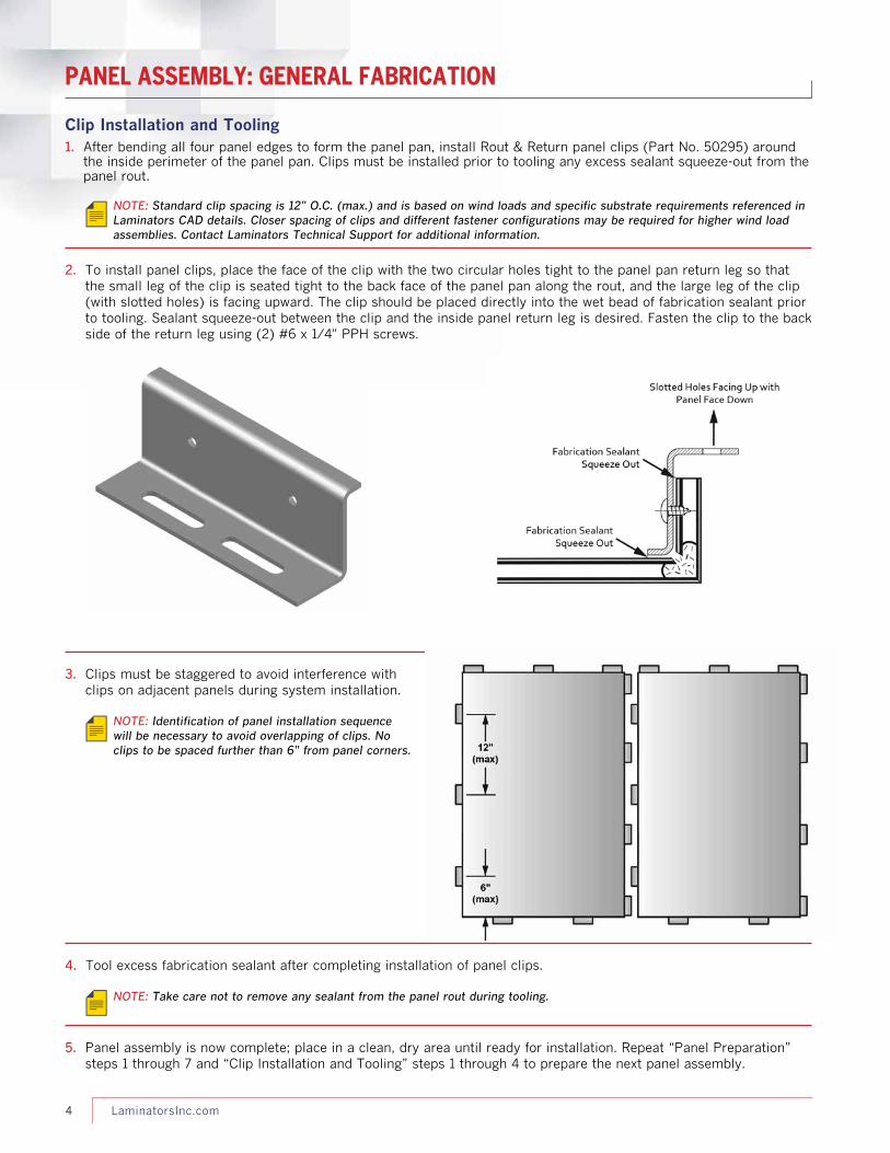
Clip Installation and Tooling1. After bending all four panel edges to form the panel pan, install Rout & Return panel clips (Part No. 50295) around
the inside perimeter of the panel pan. Clips must be installed prior to tooling any excess sealant squeeze-out from the panel rout.
Note: Standard clip spacing is 12" o.C. (max.) and is based on wind loads and specific substrate requirements referenced in Laminators CAD details. Closer spacing of clips and different fastener configurations may be required for higher wind load assemblies. Contact Laminators technical Support for additional information.
2. To install panel clips, place the face of the clip with the two circular holes tight to the panel pan return leg so that the small leg of the clip is seated tight to the back face of the panel pan along the rout, and the large leg of the clip (with slotted holes) is facing upward. The clip should be placed directly into the wet bead of fabrication sealant prior to tooling. Sealant squeeze-out between the clip and the inside panel return leg is desired. Fasten the clip to the back side of the return leg using (2) #6 x 1/4" PPH screws.
3. Clips must be staggered to avoid interference with clips on adjacent panels during system installation.
Note: Identification of panel installation sequence will be necessary to avoid overlapping of clips. No clips to be spaced further than 6" from panel corners.
4. Tool excess fabrication sealant after completing installation of panel clips.
Note: take care not to remove any sealant from the panel rout during tooling.
5. Panel assembly is now complete; place in a clean, dry area until ready for installation. Repeat “Panel Preparation” steps 1 through 7 and “Clip Installation and Tooling” steps 1 through 4 to prepare the next panel assembly.
PANEL ASSEMbLY: GENERAL FAbRICATION

5Tech Support: 800.523.2347
Rout & Return panel assemblies can be made to turn inside and outside corners and transition from fascia to soffit conditions provided that special fabrication procedures are followed.
1. Follow “Panel Preparation” steps 1 through 4 to prepare the panel for fabrication.
2. Provide an additional panel rout across the panel at the desired location of the corner bend. Verify that the depth of the router bit is properly set so that the entire panel core is removed and the back of the aluminum face metal is lightly scored during the process.
Note: the additional rout for the corner bend is to be located on the back of the panel (non-finish side) regardless of fabrication for inside or outside corners.
3. After all routing is completed, carefully cut across the return leg portion of the panel using aviation snips or heavy-duty scissors. For inside corners, a straight cut is required to separate the return legs along each face. For outside corners, the triangular section shown in step 5 below (measured at 45° angles from the rout) must be removed to facilitate bending of the panel.
4. Deburr panel edges and apply fabrication sealant to all panel routs per “Panel Preparation” steps 5 and 6.
5. After folding all panel return legs to 90° angles, gently fold the entire panel assembly along the corner rout to create either an inside or outside corner panel assembly.
Note: Both inside and outside corner panel assemblies can be used to transition from fascia to soffit conditions provided that soffit venting requirements are followed. Refer to Laminators CAD details or contact Laminators technical Support for the most current information on soffit venting requirements.
PANEL ASSEMbLY: CORNERS AND SOFFIT TRANSITIONS

6 LaminatorsInc.com
PANEL ASSEMbLY: CORNERS AND SOFFIT TRANSITIONS
6. All panel corners must be reinforced using 1" x 1" x .050" continuous aluminum angles (Part No. 44DS-ANGLE) installed across the full length of the corner rout. Tool excess fabrication sealant squeeze-out from corner rout prior to installation of reinforcement angle to facilitate proper fit. Set the reinforcement angle in full bed of fabrication sealant along folded corner rout. Apply and tool additional fabrication sealant to corner routs as required to provide full coverage for the contact area between the angle and back of panel.
7. Fasten the angle to the back of the panel using (2) #6 or #8 x 1/4" PPH screws installed at 12" O.C. (one screw per angle leg).
8. Complete folding of panel return legs per “Panel Preparation” step 7.
9. Install panel clips and tool excess fabrication sealant per “Clip Installation and Tooling” steps 1 through 4 to com-plete panel assembly. Store panel assembly in a clean, dry area until ready for installation.

7Tech Support: 800.523.2347
TYPICAL WALL LAYOUT AND STIFFENING REQUIREMENTS
The Rout & Return installation system requires panel stiffeners to provide transfer of wind loads between the panel assembly and the substrate. Panel stiffeners are fastened to the substrate prior to panel system installation. Laminators approved panel adhesive is applied to the panel stiffeners and will contact the back face of the panel assembly following installation.
Note: For the purposes of this manual, installation layout will be shown over exterior-grade plywood sheathing with an air and water barrier. Installation over CMU block, concrete, continuous insulation, and exterior-grade gypsum sheathing are possible
provided that special considerations are followed (refer to Laminators CAD details or contact Laminators technical Support for additional information). Please note that alternate substrate requirements may increase the labor and cost associated with the installation of the Rout & Return system. An established drainage plane with an air and water barrier is required for the system to function properly regardless of substrate.
Typical Wall Layout1. Exterior-grade plywood sheathing (5/8" minimum) with an air and water barrier. Type and permeability
of air and water barrier to be determined by Design Professional of Record.
2. Fasten base wall flashing to plywood sheathing.
3. Lap air and water barrier splice over metal flashing in shingle fashion.
4. Hat channels (7/8" depth, 18-gauge minimum, SSMA 087F125-43) installed as panel stiffeners.
5. Laminators approved panel adhesive applied to face of panel stiffeners.
Note: Required panel stiffening and panel adhesive layout to be determined based on project-specific wind loads as determined by the Design Professional of Record. typical stiffener layouts are 16" to 32" o.C. (depending on wind load requirements). Some
substrates require stiffeners to be oriented horizontally. Refer to Laminators CAD details or contact Laminators technical Support for additional information.

8 LaminatorsInc.com
SYSTEM INSTALLATION
The Rout & Return installation system is a non-progressive system that uses prefabricated Omega-Lite® panel assemblies with discrete clips on all sides to facilitate connection to the substrate. Planning for panel system layout is required to achieve consistent joint spacing and avoid overlapping of panel clips at adjacent panel assemblies. Typical joint size for the Rout & Return installation system is 1/2"; however, sizes can be varied based on desired aesthetic. Panel joints are sealed with silicone sealants.
Note: For soffits and fascia-to-soffit transitions, refer to Laminators CAD details and technical bulletins (available at LaminatorsInc.com) regarding size limitations and venting requirements
Typical Installation Procedures1. Layout panel joint lines (account for actual joint width in relation to edge of panel).
2. Align panel assembly squarely with joint lines and fasten clips as required to hold panel in place but allow for adjustment.
3. Use shims of desired joint thickness to achieve consistent joint size and alignment with adjacent panel assemblies.
4. Check panel assembly alignment and complete fastening of clips to substrate using (2) fasteners per clip (for fastener size refer to Laminators CAD details). Use long slotted holes in clips to adjust fastener placement as required in the event of obstructions, broken fasteners, stripped holes, etc.
5. Repeat steps 2 through 4 to continue panel system installation.
6. Install sealant joints (refer to “Joint Treatment” steps 1 through 4).
Note: Remove masking along panel return legs and 2" minimum around perimeter of panel face prior to installation of sealant joints.
Refer to CAD details at LaminatorsInc.com for details on flashing interfaces with the panel system at wall openings, roofs, parapets, grade interfaces, and dissimilar materials.
Joint Treatment1. Comply with sealant manufacturer installation requirements and ASTM C1193 Standard Guide for Use of Joint
Sealants as applicable to project conditions and specified materials.
2. Verify appropriately sized, closed-cell backer rod is installed in joints to produce cross-sectional shapes and depths relative to joint widths that allow for optimum sealant movement capability.
3. Verify joint sealant completely fills recesses and provides a uniform cross-section of material.
4. Tool sealants according to requirements in project specifications immediately after sealant application and before skinning or curing begins.

9Tech Support: 800.523.2347
Essential Equipment• Aluminum brake capable of bending 0.060" aluminum
• Laminators router bit (Part No. RB 1/2) - Custom-designed carbide router bit with 1/2"
shank only available from Laminators Inc.
• Miter saw or chop saw with 10" (min.)-diameter blade rated for cutting non-ferrous material
• Circular saw or table saw with 40-tooth blade (min.)
• Caulking gun (automatic gun recommended for consistent application)
• Screw gun/drill - Insert bit holder with 1-1/2"-long Phillips bit
• Deburring tool (Part No. DEBURRING TOOL)
• Aviation snips or heavy-duty scissors
• Plastic putty knife to remove excess caulk and adhesive from panels
• Metal file
• Utility knife
• Tape measure
• Protective gear (safety glasses, gloves to handle panels, etc.) - Jobsite safety is the responsibility of the panel installer.
Essential Materials• Panels
• Panel clips (Part No. 50295)
• Reinforcement angle (Part No. 44DS-ANGLE) - For reinforcement of all fabricated panel corners
and soffit transitions
• Extrusions (optional) - 1-Piece Tight-Fit H-Molding (Part No. 4505X) –
optional for use in folding panel legs
• Color-matched flat stock aluminum for fabrication of flashings and copings
• Panel stiffeners - 7/8" cold-formed hat channels, 18 gauge (min.),
SSMA designation: 087F125-43
• Closed-cell backer rod (appropriately sized for desired joint width)
• Mineral spirits and rags
• Touch-up paint
• Fasteners (refer to Laminators CAD details for fastener size and spacing requirements)
• Silicone sealant*
• Fabrication sealant*
• Panel adhesive* (required if installing panel stiffeners)
* For the most current list of approved silicone sealants, fabrication sealants, and adhesives, visit LaminatorsInc.com.
ESSENTIAL EQUIPMENT AND MATERIALS

3255 Penn Street , Hatf ie ld , PA 19440-1731
8 0 0 . 5 2 3 . 2 3 47 I L a m i n a t o r s I n c . c o m
©2016 Laminators Inc. All rights reserved. (10/16)